JP2013239341A - Illumination device and driving method therefor - Google Patents
Illumination device and driving method thereforDownload PDFInfo
- Publication number
- JP2013239341A JP2013239341AJP2012111537AJP2012111537AJP2013239341AJP 2013239341 AJP2013239341 AJP 2013239341AJP 2012111537 AJP2012111537 AJP 2012111537AJP 2012111537 AJP2012111537 AJP 2012111537AJP 2013239341 AJP2013239341 AJP 2013239341A
- Authority
- JP
- Japan
- Prior art keywords
- pulse signal
- light emitting
- lighting device
- driving
- unit
- Prior art date
- Legal status (The legal status is an assumption and is not a legal conclusion. Google has not performed a legal analysis and makes no representation as to the accuracy of the status listed.)
- Pending
Links
- 238000000034methodMethods0.000titleclaimsabstractdescription20
- 238000005286illuminationMethods0.000titleclaimsabstractdescription19
- 230000006872improvementEffects0.000claimsdescription4
- 230000001360synchronised effectEffects0.000claimsdescription4
- 230000000694effectsEffects0.000description9
- 238000010586diagramMethods0.000description7
- 239000011159matrix materialSubstances0.000description6
- 238000012937correctionMethods0.000description5
- 230000008447perceptionEffects0.000description4
- 230000007423decreaseEffects0.000description3
- 240000004050Pentaglottis sempervirensSpecies0.000description2
- 235000004522Pentaglottis sempervirensNutrition0.000description2
- 230000001747exhibiting effectEffects0.000description2
- 230000010363phase shiftEffects0.000description2
- 238000011160researchMethods0.000description2
- 230000008054signal transmissionEffects0.000description2
- 230000000007visual effectEffects0.000description2
- OAICVXFJPJFONN-UHFFFAOYSA-NPhosphorusChemical compound[P]OAICVXFJPJFONN-UHFFFAOYSA-N0.000description1
- 230000008901benefitEffects0.000description1
- 230000005540biological transmissionEffects0.000description1
- 230000004397blinkingEffects0.000description1
- 230000008859changeEffects0.000description1
- 238000006243chemical reactionMethods0.000description1
- 230000000052comparative effectEffects0.000description1
- 239000002131composite materialSubstances0.000description1
- 238000007796conventional methodMethods0.000description1
- 238000005401electroluminescenceMethods0.000description1
- 238000005265energy consumptionMethods0.000description1
- 238000005516engineering processMethods0.000description1
- 230000006870functionEffects0.000description1
- 230000004927fusionEffects0.000description1
- 238000004020luminiscence typeMethods0.000description1
- 239000000463materialSubstances0.000description1
- 238000012986modificationMethods0.000description1
- 230000004048modificationEffects0.000description1
- 230000004043responsivenessEffects0.000description1
- 230000002207retinal effectEffects0.000description1
- 230000004936stimulating effectEffects0.000description1
- 230000004382visual functionEffects0.000description1
Images


Landscapes
- Circuit Arrangement For Electric Light Sources In General (AREA)
Abstract
Description
Translated fromJapanese本発明は、LEDなどの発光素子を用いた照明装置及びその駆動方法に関する。 The present invention relates to a lighting device using a light emitting element such as an LED and a driving method thereof.
文字や記号などの情報をドットマトリクスによって画像表示する手段として、例えば、発光ダイオード(LED:Light Emitting Diode)をマトリクス状に配置したマトリクス表示装置が知られている(例えば、特許文献1参照)。このようなマトリクス表示装置は、電車内の電光文字表示装置などに広く用いられている。すなわち、複数のLEDがマトリクス状に配置された表示領域を備え、この表示領域に文字や記号などを表示させることにより、ニュースなどの情報を伝えることができる。 As a means for displaying information such as characters and symbols in a dot matrix, for example, a matrix display device in which light emitting diodes (LEDs) are arranged in a matrix is known (for example, see Patent Document 1). Such a matrix display device is widely used for an electric character display device in a train. That is, information such as news can be conveyed by providing a display area in which a plurality of LEDs are arranged in a matrix and displaying characters and symbols in the display area.
また、ブロッカ・ザルツァー(Broca−Sulzer)効果を利用した照明装置が知られている(例えば、特許文献2参照)。この照明装置によれば、照明用発光ダイオードを周期的にパルス状に発光させることにより、少ない発光量で大きな心理的輝度を得ることができる。そのため、エネルギー消費の小さい照明装置を実現することが可能である。 Moreover, the illuminating device using the Broca-Sulzer effect is known (for example, refer patent document 2). According to this illuminating device, a large psychological luminance can be obtained with a small amount of light emission by periodically illuminating the illuminating light emitting diode in a pulse shape. Therefore, a lighting device with low energy consumption can be realized.
また、点滅する光点の識別の際,臨界融像頻度は,網膜照度の対数に比例するというフェリーポーター(Ferry-Porter)の法則も知られている。 Also, Ferry-Porter's law is known in which the critical fusion frequency is proportional to the logarithm of retinal illuminance when identifying a flashing light spot.
また、オフィス照明環境における明るさの変動知覚に関する研究が知られている。この研究結果によれば、視覚機能上、変動比0.92から1.06、すなわち、おおよそ7%程度の人工照明の変動は、その変動時間によらず、知覚することはできない。しかし、実オフィスにおけるオフィスワーカの作業状況からすると、最小知覚変動比は、0.88から1.13、さらに変動時間を設けて連続的に変動させた場合は、0.8から1.3と、閾値が上昇する(非特許文献1参照)。 In addition, research on perception of brightness fluctuations in office lighting environments is known. According to the result of this research, the fluctuation ratio of the artificial illumination of 0.92 to 1.06, that is, about 7%, cannot be perceived in terms of the visual function regardless of the fluctuation time. However, according to the work situation of the office worker in the actual office, the minimum perceptual fluctuation ratio is 0.88 to 1.13, and when continuously fluctuating with a fluctuation time, 0.8 to 1.3. The threshold value increases (see Non-Patent Document 1).
しかしながら、従来技術では、見た目の明るさを維持しつつ消費電力を削減しようとすると、チラツキ(フリッカ)を感じるという課題があった。看板照明などの照明装置は、電光文字表示装置に比べて長時間利用されるため、チラツキを低減することが重要である。 However, the conventional technique has a problem of feeling flicker when attempting to reduce power consumption while maintaining the apparent brightness. It is important to reduce flicker because lighting devices such as signboard lighting are used for a longer period of time than electric light character display devices.
本発明の目的は、見た目の明るさを維持しつつ、消費電力を削減した場合でもチラツキを低減可能な照明装置及びその駆動方法を提供することにある。 An object of the present invention is to provide an illumination device capable of reducing flicker even when power consumption is reduced while maintaining the apparent brightness, and a driving method thereof.
本発明の一態様によれば、発光素子を有する発光部と、前記発光部に電力を供給して前記発光部を駆動する駆動部と、所定周波数のパルス信号を生成して前記駆動部に供給するパルス信号供給部と、前記パルス信号のデューティ比がその最大値から所定値までの範囲で連続的に繰り返し変動するように前記パルス信号を制御するパルス信号制御部とを備える照明装置が提供される。 According to one aspect of the present invention, a light emitting unit having a light emitting element, a driving unit that supplies power to the light emitting unit to drive the light emitting unit, and generates a pulse signal having a predetermined frequency and supplies the pulse signal to the driving unit. And a pulse signal control unit that controls the pulse signal so that a duty ratio of the pulse signal continuously and repeatedly fluctuates in a range from the maximum value to a predetermined value. The
また、本発明の他の態様によれば、発光素子を有する発光部を駆動する駆動部が前記発光部に電力を供給して前記発光部を駆動する駆動ステップと、所定周波数のパルス信号を生成して前記駆動部に供給するパルス信号供給ステップと、前記パルス信号のデューティ比がその最大値から所定値までの範囲で連続的に繰り返し変動するように前記パルス信号を制御するパルス信号制御ステップとを有する照明装置の駆動方法が提供される。 According to another aspect of the present invention, a driving unit that drives a light emitting unit having a light emitting element supplies power to the light emitting unit to drive the light emitting unit, and generates a pulse signal having a predetermined frequency. And a pulse signal control step for controlling the pulse signal so that a duty ratio of the pulse signal continuously and repeatedly fluctuates in a range from a maximum value to a predetermined value. There is provided a method of driving an illumination device having the following.
本発明によれば、見た目の明るさを維持しつつ、消費電力を削減した場合でもチラツキを低減可能な照明装置及びその駆動方法を提供することができる。 According to the present invention, it is possible to provide an illuminating device and a driving method thereof that can reduce flicker even when power consumption is reduced while maintaining the apparent brightness.
次に、図面を参照して、本発明の実施の形態を説明する。以下の図面の記載において、同一又は類似の部分には同一又は類似の符号を付している。ただし、図面は模式的なものであり、各構成部品の厚みと平面寸法との関係、各層の厚みの比率等は現実のものとは異なることに留意すべきである。したがって、具体的な厚みや寸法は以下の説明を参酌して判断すべきものである。又、図面相互間においても互いの寸法の関係や比率が異なる部分が含まれていることはもちろんである。 Next, embodiments of the present invention will be described with reference to the drawings. In the following description of the drawings, the same or similar parts are denoted by the same or similar reference numerals. However, it should be noted that the drawings are schematic, and the relationship between the thickness of each component and the planar dimensions, the ratio of the thickness of each layer, and the like are different from the actual ones. Therefore, specific thicknesses and dimensions should be determined in consideration of the following description. Moreover, it is a matter of course that portions having different dimensional relationships and ratios are included between the drawings.
又、以下に示す実施の形態は、この発明の技術的思想を具体化するための装置や方法を例示するものであって、この発明の実施の形態は、各構成部品の材質、形状、構造、配置等を下記のものに特定するものでない。この発明の実施の形態は、特許請求の範囲において、種々の変更を加えることができる。 Further, the embodiments described below exemplify apparatuses and methods for embodying the technical idea of the present invention, and the embodiments of the present invention include the material, shape, and structure of each component. The arrangement is not specified below. Various modifications can be made to the embodiment of the present invention within the scope of the claims.
[第1の実施の形態]
以下、図1〜図7を参照して、第1の実施の形態について説明する。[First Embodiment]
The first embodiment will be described below with reference to FIGS.
(照明装置)
第1の実施の形態に係る照明装置100は、図1に示すように、LEDなどの発光素子を有する発光部1と、発光部1に電力を供給して発光部1を駆動する駆動部2と、所定周波数のパルス信号P31,P32,P33,…を生成して駆動部2に供給するパルス信号供給部3と、パルス信号P31,P32,P33,…のデューティ比がその最大値から所定値までの範囲で連続的に繰り返し変動するようにパルス信号P31,P32,P33,…を制御するパルス信号制御部4とを備える。例えば、パルス信号制御部4は、デューティ比100%から85%までの範囲で連続的に繰り返し変動させる。(Lighting device)
As shown in FIG. 1, the
(基本パルス信号、フェイク信号)
第1の実施の形態に係る照明装置100に適用される基本パルス信号P1とフェイク信号P2は、図2に示すように表される。マトリクス表示装置の低消費技術では、図2に示すように、基本パルス信号P1とは別に、ブロッカ・ザルツァー効果を発揮させるためのフェイク信号P2を用いる。フェイク信号P2とは、ブロッカ・ザルツァー効果を発揮させるための擬似信号をいう。フェイク信号P2は、基本パルス信号P1のデューティ比よりも小さなデューティ比を有し、かつ基本パルス信号P1のピーク出力値の2倍以上のピーク出力値を有するパルス信号で構成される。(Basic pulse signal, fake signal)
The basic pulse signal P1 and the fake signal P2 applied to the
(ブロッカ・ザルツァー効果)
ブロッカ・ザルツァー効果とは、明るさの知覚に関する人間の生理的視覚特性であり、刺激光の持続時間によってその明るさ知覚が変わる現象をいう。例えば、図3に示すように、増分光の輝度を一定に保ちながらその呈示時間を増加させていくと、見た目の明るさ(比較刺激強度)は呈示時間と共に増加し、所定時間経過して極大値を迎えた後に下降し、やがて一定水準となる場合がある。ここで、呈示時間とは、オン・オフの点滅時間に相当する時間である。すなわち、刺激の呈示時間が極短い場合、その見た目の明るさは、物理的な輝度の等しい定常光の明るさを下回るが、刺激の呈示時間が中程度(50〜100ms程度)の場合、その見た目の明るさは、物理的な輝度の等しい定常光の明るさを上回るという現象が生じる。このような現象を発見者に因んでブロッカ・ザルツァー現象と呼ぶ。(Blocker Salzer effect)
The Blocker-Salzer effect is a human physiological visual characteristic related to the perception of brightness, and refers to a phenomenon in which the brightness perception changes depending on the duration of stimulus light. For example, as shown in FIG. 3, when the presentation time is increased while keeping the luminance of the incremental light constant, the apparent brightness (comparative stimulus intensity) increases with the presentation time, and reaches a maximum after a predetermined time. After reaching the value, it may fall and eventually reach a certain level. Here, the presentation time is a time corresponding to an on / off blinking time. That is, when the stimulus presentation time is extremely short, the apparent brightness is lower than that of stationary light having the same physical brightness, but when the stimulus presentation time is moderate (about 50 to 100 ms) A phenomenon occurs in which the apparent brightness exceeds the brightness of stationary light having the same physical luminance. This phenomenon is called the Blocker-Salzer phenomenon due to the discoverer.
ブロッカ・ザルツァー効果の実験結果は、図3に示すように表される。ブロッカ・ザルツァー効果によれば、図3に示すように、周波数20Hz程度で刺激光を呈示した場合、特に高い視覚効果が得られる。 The experimental results of the Blocker-Salzer effect are expressed as shown in FIG. According to the Blocker-Salzer effect, as shown in FIG. 3, when stimulating light is presented at a frequency of about 20 Hz, a particularly high visual effect is obtained.
一方、発光素子としてLEDを用いた場合、周波数20Hz程度でLEDを点灯させるとチラツキが生じ、見る者に不快感を与えてしまう。このため、第1の実施の形態に係る照明装置100においては、見た目の明るさを維持しつつ消費電力を削減した場合でもチラツキを低減することができるように、図5に示す回路構成を採用している。 On the other hand, when an LED is used as the light-emitting element, flickering occurs when the LED is turned on at a frequency of about 20 Hz, which causes discomfort to the viewer. For this reason, in the illuminating
(波形例)
第1の実施の形態に係る照明装置100に適用されるパルス信号P31,P32,P33,…の電流波形は、図4(a)に示すように表され、図4(a)に対応したデューティ比の時間変動は、図4(b)に示すように表される。(Example of waveform)
The current waveforms of the pulse signals P31, P32, P33,... Applied to the
図4(a)では、パルス信号P31,P32,P33,…の周波数は500Hzである場合を例示している。図4(a)に示すように、パルス信号P31,P32,P33,…のデューティ比は、「小」から「大」へ、また「大」から「小」へ連続的に繰り返し変動している。具体的には、パルス信号P31からP34にかけてデューティ比が徐々に大きくなっている。また、パルス信号P34からP37にかけてデューティ比が徐々に小さくなっている。図示していないが、以降のパルス信号P38,…についても同様の変動を繰り返す。ここで、パルス信号P31,P32,P33,…には、例えば、パルス幅変調(PWM:Pulse Width Modulation)信号、パルス数変調(PNM:Pulse Number Modulation)信号、あるいは、パルス密度変調(PDM:Pulse Density Modulation)信号などを適用可能である。 4A illustrates the case where the frequency of the pulse signals P31, P32, P33,... Is 500 Hz. As shown in FIG. 4A, the duty ratio of the pulse signals P31, P32, P33,... Continuously and repeatedly fluctuates from “small” to “large” and from “large” to “small”. . Specifically, the duty ratio gradually increases from the pulse signals P31 to P34. Further, the duty ratio gradually decreases from the pulse signal P34 to P37. Although not shown, the same fluctuation is repeated for the subsequent pulse signals P38,. Here, the pulse signals P31, P32, P33,... Include, for example, a pulse width modulation (PWM) signal, a pulse number modulation (PNM) signal, or a pulse density modulation (PDM: Pulse). Density Modulation) signal can be applied.
デューティ比は、図4(b)に示すように、最大値100%から所定値85%までの範囲で連続的に繰り返し変動する。図4(b)では、デューティ比が100%から85%まで変動する周期が60Hzである場合を例示している。デューティ比は、図4(b)に示すように、一定速度で低下して時刻t1で85%になる。その後、一定速度で上昇して時刻t2で100%になる。更に、一定速度で低下して時刻t3で85%になる。時刻t3以降も同様の変動を繰り返す。 As shown in FIG. 4B, the duty ratio continuously and repeatedly fluctuates within a range from a maximum value of 100% to a predetermined value of 85%. FIG. 4B illustrates a case where the cycle in which the duty ratio varies from 100% to 85% is 60 Hz. As shown in FIG. 4B, the duty ratio decreases at a constant speed and reaches 85% at time t1. Then, it rises at a constant speed and reaches 100% at time t2. Furthermore, it decreases at a constant speed and reaches 85% at time t3. Similar fluctuations are repeated after time t3.
このようにデューティ比を変動させた場合、図4(b)中の斜線領域に相当する分、トータルの消費電力は削減されることになる。この場合、明るさの変動を知覚するかどうかについて、20名程度にアンケート調査を行った。その結果、ほとんどの被験者は明るさの変動を知覚しなかった。すなわち、第1の実施の形態に係る照明装置100によると、見た目の明るさを維持しつつ消費電力を削減することが可能である。 When the duty ratio is varied in this way, the total power consumption is reduced by an amount corresponding to the shaded area in FIG. In this case, a questionnaire survey was conducted on about 20 people as to whether to perceive fluctuations in brightness. As a result, most subjects did not perceive brightness fluctuations. That is, according to the illuminating
この効果は、発光素子を疑似白色LEDにすると、より顕著である。すなわち、疑似白色LEDは、青色LEDによって黄色蛍光体を発光させることで白色を実現するものである。人間の目は、青色の変化には鈍感であるため、発光素子を疑似白色LEDにすると、明るさの変動を知覚しにくくなる。その結果、デューティ比をより大きく変動させることができるので、消費電力をより多く削減することが可能となる。 This effect is more remarkable when the light emitting element is a pseudo white LED. That is, the pseudo white LED realizes white by causing a yellow phosphor to emit light by a blue LED. Since the human eye is insensitive to the blue color change, if the light emitting element is a pseudo white LED, it becomes difficult to perceive fluctuations in brightness. As a result, the duty ratio can be changed more greatly, so that the power consumption can be further reduced.
ここでは、デューティ比が最大値100%から所定値85%までの範囲で変動する場合を例示しているが、デューティ比の最大値は100%に限定されるものではなく、また所定値は85%以上であればよい。85%より低くした場合は、明るさの変動を知覚する可能性がある。 Here, the case where the duty ratio fluctuates in the range from the
また、パルス信号P31,P32,P33,…の周波数が500Hzである場合を例示しているが、この周波数は500Hz以上であればよい。500Hz以上にすれば、精度よくチラツキを低減することができる。 Moreover, although the case where the frequency of pulse signal P31, P32, P33, ... is 500 Hz is illustrated, this frequency should just be 500 Hz or more. If it is set to 500 Hz or more, flicker can be reduced with high accuracy.
また、デューティ比が100%から85%まで変動する周期が60Hzである場合を例示しているが、この周期は60Hz以上であればよい。60Hzより低くした場合は、明るさの変動を知覚する可能性がある。 Moreover, although the case where the cycle in which the duty ratio fluctuates from 100% to 85% is 60 Hz is illustrated, this cycle may be 60 Hz or more. When the frequency is lower than 60 Hz, there is a possibility of perceiving fluctuations in brightness.
(回路例)
第1の実施の形態に係る照明装置100の模式的回路ブロック構成は、図5に示すように表される。図5中の実線は電力信号の伝送線を主として表し、破線の矢印は制御信号の伝送方向を示す。(Circuit example)
A schematic circuit block configuration of the
保護回路12は、AC電源11からの入力電圧(交流電圧)から後段の回路部を保護する。ノイズフィルター13は、保護回路11を介して入力された入力電圧からノイズ成分を除去する。ノイズ成分が除去された交流電圧は、AC/DCコンバータ14で直流電圧に変換され、DC/DCコンバータ15・25で所定のDC電圧値に変換される。 The
PWM発生器16は、DC/DCコンバータ15の出力をパルス幅変調して、メインSWPWM信号を発生し、スイッチングDC/DCコンバータ20に供給する。 The PWM generator 16 performs pulse width modulation on the output of the DC /
コンパレータ18は、電流−電圧変換器23から出力される電圧を基準電圧発生器17からの基準電圧と比較し、その比較結果をスイッチングDC/DCコンバータ20に供給する。ここで、基準電圧発生器17の基準電圧は、DC/DCコンバータ15のDC出力電圧に対応する。 The
DC/DCコンバータ25に接続されたタイマー回路26には、パルス信号をONにするタイミングが設定されている。 The
PWM発生器27は、タイマー回路26のタイミング設定に基づいて、デューティ比100%〜x%までの範囲でスイープPWM信号を生成して、スイッチングDC/DCコンバータ20に供給する。 The PWM generator 27 generates a sweep PWM signal in a duty ratio range of 100% to x% based on the timing setting of the
スイッチングDC/DCコンバータ20は、AC/DCコンバータ14に接続された力率改善回路19により力率改善されたDC電圧を、メインSWPWM信号およびスイープPWM信号によるPWM制御に基づいて、電流−電圧変換器23に供給する。 The switching DC /
結果として、電流−電圧変換器23に接続されたLEDなどの負荷30には、メインSWPWM信号およびスイープPWM信号によりPWM制御され、定電流化されたパルス信号P31,P32,P33,…が供給される。 As a result, the pulse signals P31, P32, P33,..., Which are PWM-controlled by the main SWPWM signal and the sweep PWM signal and converted to a constant current, are supplied to the
このため、第1の実施の形態に係る照明装置100においては、見た目の明るさを維持しつつ消費電力を削減した場合でもチラツキを低減することができる。 For this reason, in the
第1の実施の形態に係る照明装置に供給される電流パルス信号の波形例であって、500Hzのパルス信号が5kHz以上の複数の波形の合成波で構成され、高速にスイッチングされている様子は、図6に示すように表される。図6中の丸印は、500Hzのパルス信号P32が5kHz以上の波で構成され、高速にスイッチングされている様子を示している。他の波形も同様である。図6の波形は、PDM波形に対応している。 It is a waveform example of a current pulse signal supplied to the lighting apparatus according to the first embodiment, and a state in which a 500 Hz pulse signal is composed of a composite wave of a plurality of waveforms of 5 kHz or more and is switched at high speed. , As shown in FIG. The circles in FIG. 6 indicate that the 500 Hz pulse signal P32 is composed of waves of 5 kHz or more and is switched at high speed. The same applies to other waveforms. The waveform in FIG. 6 corresponds to the PDM waveform.
(応用例)
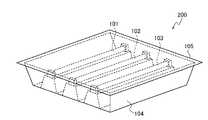
第1の実施の形態に係る照明装置100の応用例を示す模式的鳥瞰構造は、図7に示すように表される。図7では、ガソリンスタンドやコンビニエンスストアなどの看板照明200を例示している。図7に示すように、複数本の直管形LED101,102,103が収納器具104に収納されている。収納器具104の開口部は透過板105で覆われた構造となっている。なお、照明装置100は直管形に限定されるものではなく、例えば電球形、シーリングライトやペンダントライトなどであってもよい。(Application examples)
A schematic bird's-eye view structure showing an application example of the
第1の実施の形態によれば、見た目の明るさを維持しつつ消費電力を削減した場合でもチラツキを低減可能な照明装置及びその駆動方法を提供することができる。 According to the first embodiment, it is possible to provide an illuminating device and a driving method thereof that can reduce flicker even when power consumption is reduced while maintaining apparent brightness.
[第2の実施の形態]
第2の実施の形態に係る照明装置100の模式的回路ブロック構成は、図8に示すように、力率改善回路19を備えていない点を除けば、第1の実施の形態と同じである。力率改善回路19を備えれば、電力損失が増加する等の不具合を回避することができるが、力率改善回路19を備えなければ、その分だけ製品価格を抑えることができる等のメリットがある。いずれかの構成を採用するか、使用目的等に応じて決定すればよい。[Second Embodiment]
The schematic circuit block configuration of the
第2の実施の形態に係る照明装置によれば、力率改善回路を備えていないため、第1の実施の形態に比べて製品価格を抑えることができる等のメリットがある。 According to the lighting apparatus according to the second embodiment, since the power factor correction circuit is not provided, there is a merit that the product price can be suppressed as compared with the first embodiment.
第2の実施の形態によれば、見た目の明るさを維持しつつ消費電力を削減した場合でもチラツキを低減可能な照明装置及びその駆動方法を提供することができる。 According to the second embodiment, it is possible to provide an illuminating device and a driving method thereof that can reduce flicker even when power consumption is reduced while maintaining the apparent brightness.
[第3の実施の形態]
第3の実施の形態に係る照明装置100の模式的回路ブロック構成は、図9に示すように、同期回路31を備えている点を除けば、第1の実施の形態と同じである。[Third Embodiment]
The schematic circuit block configuration of the
同期回路31は、他の照明装置の電源と同期をとって、その同期信号をタイマー回路26に供給する。ここで、他の照明装置とは、第3の実施の形態に係る照明装置100と同様の照明装置の場合には、複数個並列に配置可能となる。また、第3の実施の形態に係る照明装置100とは異なる照明装置であっても良い。 The
タイマー回路26は、同期回路31から供給された同期信号に基づいてタイマー回路26のタイミング設定を変更する。このようにすれば、図7に示すように、複数本の直管LED101,102,103を用いる場合、それぞれの直管LED101,102,103で同期をとることができる。一方、簡単には、複数の照明装置間の同期を敢えて取らない動作モードを実施しても良い。 The
第3の実施の形態によれば、同期回路を備えているため、複数の照明装置間の位相ずれを回避することができ、より快適な照明装置を提供することが可能である。 According to the third embodiment, since the synchronization circuit is provided, a phase shift between a plurality of lighting devices can be avoided, and a more comfortable lighting device can be provided.
第3の実施の形態によれば、見た目の明るさを維持しつつ消費電力を削減した場合でもチラツキを低減可能な照明装置及びその駆動方法を提供することができる。 According to the third embodiment, it is possible to provide an illuminating device and a driving method thereof that can reduce flicker even when power consumption is reduced while maintaining the apparent brightness.
[第4の実施の形態]
第4の実施の形態に係る照明装置100の模式的回路ブロック構成は、図10に示すように表される。[Fourth Embodiment]
A schematic circuit block configuration of the
第4の実施の形態に係る照明装置100は、第2の実施の形態と第3の実施の形態とを組み合わせたものである。すなわち、図10に示すように、力率改善回路19を備えず、また同期回路31を備えた構成を採用している。力率改善回路19と同期回路31の機能は既に説明した通りである。 The
第4の実施の形態に係る照明装置100によれば、力率改善回路を備えていないため、第1の実施の形態に比べて製品価格を抑えることができる等のメリットがある。また、他の照明装置の電源と同期をとる同期回路を備えているため、複数の照明装置を配置し、位相ずれを回避することができ、より快適な照明装置を提供することが可能である。 According to the
第4の実施の形態によれば、見た目の明るさを維持しつつ消費電力を削減した場合でもチラツキを低減可能な照明装置及びその駆動方法を提供することができる。 According to the fourth embodiment, it is possible to provide an illuminating device and a driving method thereof that can reduce flicker even when power consumption is reduced while maintaining apparent brightness.
以上説明したように、本発明によれば、見た目の明るさを維持しつつ消費電力を削減した場合でもチラツキを低減することが可能な照明装置及びその駆動方法を提供することができる。 As described above, according to the present invention, it is possible to provide an illuminating device and a driving method thereof that can reduce flicker even when power consumption is reduced while maintaining apparent brightness.
[その他の実施の形態]
上記のように、本発明は第1〜第4の実施の形態によって記載したが、この開示の一部をなす論述および図面は例示的なものであり、この発明を限定するものであると理解すべきではない。この開示から当業者には様々な代替実施の形態、実施例および運用技術が明らかとなろう。[Other embodiments]
As described above, the present invention has been described according to the first to fourth embodiments. However, it should be understood that the descriptions and drawings constituting a part of this disclosure are exemplary and limit the present invention. should not do. From this disclosure, various alternative embodiments, examples and operational techniques will be apparent to those skilled in the art.
このように、本発明はここでは記載していない様々な実施の形態などを含む。例えば、 発光素子はLEDに限らず、応答性が高速なものであれば他の発光素子を用いてもかまわない。例えば、有機エレクトロルミネッセンス(有機EL:Organic Electro-Luminescence)素子等の有機発光素子や電気化学発光素子(Electro Chemical-Luminescence:ECL)等を用いることができる。 As described above, the present invention includes various embodiments not described herein. For example, the light emitting elements are not limited to LEDs, and other light emitting elements may be used as long as the responsiveness is high. For example, an organic light-emitting element such as an organic electroluminescence (organic EL) element, an electrochemical light-emitting element (Electrochemical-Luminescence: ECL), or the like can be used.
本発明の照明装置は、見た目の明るさを維持しつつ消費電力を削減した場合でもチラツキを低減することが必要な種々の照明装置に利用することができる。例えば、ガソリンスタンドやコンビニエンスストアなどの看板照明として利用するのが効果的である。 The lighting device of the present invention can be used for various lighting devices that need to reduce flicker even when power consumption is reduced while maintaining the apparent brightness. For example, it is effective to use as signboard lighting in a gas station or a convenience store.
1…発光部
2…駆動部
3…パルス信号供給部
4…パルス信号制御部
19…力率改善回路
31…同期回路
100…照明装置
P31〜P37…パルス信号DESCRIPTION OF SYMBOLS 1 ... Light emission part 2 ... Drive
Claims (16)
Translated fromJapanese前記発光部に電力を供給して前記発光部を駆動する駆動部と、
所定周波数のパルス信号を生成して前記駆動部に供給するパルス信号供給部と、
前記パルス信号のデューティ比がその最大値から所定値までの範囲で連続的に繰り返し変動するように前記パルス信号を制御するパルス信号制御部と
を備えることを特徴とする照明装置。A light emitting unit having a light emitting element;
A drive unit for supplying power to the light emitting unit to drive the light emitting unit;
A pulse signal supply unit that generates a pulse signal of a predetermined frequency and supplies the pulse signal to the drive unit;
An illumination device comprising: a pulse signal control unit that controls the pulse signal so that the duty ratio of the pulse signal continuously and repeatedly fluctuates in a range from the maximum value to a predetermined value.
所定周波数のパルス信号を生成して前記駆動部に供給するパルス信号供給ステップと、
前記パルス信号のデューティ比がその最大値から所定値までの範囲で連続的に繰り返し変動するように前記パルス信号を制御するパルス信号制御ステップと
を有することを特徴とする照明装置の駆動方法。A driving step of driving a light emitting unit by driving a light emitting unit having a light emitting element by supplying power to the light emitting unit;
A pulse signal supply step of generating a pulse signal of a predetermined frequency and supplying the pulse signal to the drive unit;
And a pulse signal control step of controlling the pulse signal so that the duty ratio of the pulse signal continuously and repeatedly fluctuates in a range from the maximum value to a predetermined value.
Priority Applications (3)
| Application Number | Priority Date | Filing Date | Title |
|---|---|---|---|
| JP2012111537AJP2013239341A (en) | 2012-05-15 | 2012-05-15 | Illumination device and driving method therefor |
| CN201380025456.7ACN104303598A (en) | 2012-05-15 | 2013-05-15 | Lighting device and driving method thereof |
| PCT/JP2013/063485WO2013172363A1 (en) | 2012-05-15 | 2013-05-15 | Illumination device and drive method therefor |
Applications Claiming Priority (1)
| Application Number | Priority Date | Filing Date | Title |
|---|---|---|---|
| JP2012111537AJP2013239341A (en) | 2012-05-15 | 2012-05-15 | Illumination device and driving method therefor |
Publications (1)
| Publication Number | Publication Date |
|---|---|
| JP2013239341Atrue JP2013239341A (en) | 2013-11-28 |
Family
ID=49764205
Family Applications (1)
| Application Number | Title | Priority Date | Filing Date |
|---|---|---|---|
| JP2012111537APendingJP2013239341A (en) | 2012-05-15 | 2012-05-15 | Illumination device and driving method therefor |
Country Status (1)
| Country | Link |
|---|---|
| JP (1) | JP2013239341A (en) |
Cited By (1)
| Publication number | Priority date | Publication date | Assignee | Title |
|---|---|---|---|---|
| JP2019109308A (en)* | 2017-12-15 | 2019-07-04 | 東京エレクトロン株式会社 | Substrate processing device, substrate processing method and storage medium |
Citations (3)
| Publication number | Priority date | Publication date | Assignee | Title |
|---|---|---|---|---|
| JP2009301966A (en)* | 2008-06-17 | 2009-12-24 | Toshiba Lighting & Technology Corp | Lighting system |
| JP2012023294A (en)* | 2010-07-16 | 2012-02-02 | Time Engineering Co Ltd | Led lighting device |
| JP2012038647A (en)* | 2010-08-10 | 2012-02-23 | Jkb Co Ltd | Led unit |
- 2012
- 2012-05-15JPJP2012111537Apatent/JP2013239341A/enactivePending
Patent Citations (3)
| Publication number | Priority date | Publication date | Assignee | Title |
|---|---|---|---|---|
| JP2009301966A (en)* | 2008-06-17 | 2009-12-24 | Toshiba Lighting & Technology Corp | Lighting system |
| JP2012023294A (en)* | 2010-07-16 | 2012-02-02 | Time Engineering Co Ltd | Led lighting device |
| JP2012038647A (en)* | 2010-08-10 | 2012-02-23 | Jkb Co Ltd | Led unit |
Cited By (1)
| Publication number | Priority date | Publication date | Assignee | Title |
|---|---|---|---|---|
| JP2019109308A (en)* | 2017-12-15 | 2019-07-04 | 東京エレクトロン株式会社 | Substrate processing device, substrate processing method and storage medium |
Similar Documents
| Publication | Publication Date | Title |
|---|---|---|
| US7586271B2 (en) | Efficient lighting | |
| EP1986470A3 (en) | Apparatus amd method to provide a hybrid linear/switching current source, such as for high-efficiency, wide dimming range light emitting diode (LED) backlighting | |
| JP2013122846A (en) | Lighting device | |
| CN103155708A (en) | Integrated power IC for LED lighting | |
| Wang et al. | Dimmable and cost-effective DC driving technique for flicker mitigation in LED lighting | |
| CN110536502A (en) | LED lamp device and luminaire | |
| JP2009054928A (en) | Light emitting element control circuit | |
| US7294978B1 (en) | Efficient lighting | |
| US7372441B2 (en) | Burst pulse circuit for signal lights and method | |
| US8427065B2 (en) | Driving circuit for light emitting elements | |
| CN101937651B (en) | Light emitting diode driving method | |
| JP2013239341A (en) | Illumination device and driving method therefor | |
| WO2010065300A3 (en) | Device and method for periodic diode actuation | |
| JP2009289442A (en) | Led lamp mountable on general fluorescent lamp luminaire | |
| WO2013172363A1 (en) | Illumination device and drive method therefor | |
| JP2013243037A (en) | Illuminating device and method of driving the same | |
| CN1678157A (en) | Method for regulating and controlling LED lamp lightness | |
| JP5780607B2 (en) | Illumination device and dimming method | |
| KR101464083B1 (en) | Ac direct connection type LED driving circuit having function of flicker reduction | |
| JP2018055785A (en) | Lighting equipment and lighting apparatus | |
| US20130200817A1 (en) | Method for Minimizing Stroboscopic Effects in PWM Driven Lighting | |
| US8659234B2 (en) | Electronic candle | |
| Kudryashov et al. | Experimental PWM controlled device | |
| JP2017117600A (en) | Lighting method of lighting device and lighting device | |
| JP2018014375A (en) | LED flashing control method |
Legal Events
| Date | Code | Title | Description |
|---|---|---|---|
| A621 | Written request for application examination | Free format text:JAPANESE INTERMEDIATE CODE: A621 Effective date:20150501 | |
| A131 | Notification of reasons for refusal | Free format text:JAPANESE INTERMEDIATE CODE: A131 Effective date:20160421 | |
| A02 | Decision of refusal | Free format text:JAPANESE INTERMEDIATE CODE: A02 Effective date:20170110 |