JP2013237348A - Negative pressure pump control device for vehicle - Google Patents
Negative pressure pump control device for vehicleDownload PDFInfo
- Publication number
- JP2013237348A JP2013237348AJP2012111400AJP2012111400AJP2013237348AJP 2013237348 AJP2013237348 AJP 2013237348AJP 2012111400 AJP2012111400 AJP 2012111400AJP 2012111400 AJP2012111400 AJP 2012111400AJP 2013237348 AJP2013237348 AJP 2013237348A
- Authority
- JP
- Japan
- Prior art keywords
- negative pressure
- pump
- vehicle
- pressure pump
- air
- Prior art date
- Legal status (The legal status is an assumption and is not a legal conclusion. Google has not performed a legal analysis and makes no representation as to the accuracy of the status listed.)
- Granted
Links
Images


Landscapes
- Valves And Accessory Devices For Braking Systems (AREA)
Abstract
Translated fromJapaneseDescription
Translated fromJapanese本発明は、走行用モータを搭載した車両において、ブレーキブースタに負圧を生じさせるための負圧ポンプを制御する負圧ポンプ制御装置に関するものである。 The present invention relates to a negative pressure pump control device for controlling a negative pressure pump for generating a negative pressure in a brake booster in a vehicle equipped with a traveling motor.
エンジンを搭載した車両には、スロットルバルブよりも下流側の吸気管内に発生する負圧を用いて、運転者によるブレーキ装置の操作力をアシストするブレーキブースタが搭載されている。このブレーキブースタでは、吸気管内の負圧と大気圧との差圧を用いてブレーキ装置の操作力がアシストされる。 A vehicle equipped with an engine is equipped with a brake booster that assists the operating force of the brake device by the driver using negative pressure generated in the intake pipe downstream of the throttle valve. In this brake booster, the operating force of the brake device is assisted using the differential pressure between the negative pressure in the intake pipe and the atmospheric pressure.
しかしながら、電気自動車(EV)にはエンジンが装備されておらず、また、ハイブリッド自動車(HEV)でのモータ単体走行時にはエンジンが休止されているため、吸気管内の負圧を利用することができない。このため、走行用モータを搭載した車両には、ブレーキブースタで用いる負圧を発生させるための負圧ポンプが搭載されている。このような電気自動車の負圧ポンプを制御する技術は、例えば特許文献1に開示されている。 However, the electric vehicle (EV) is not equipped with an engine, and the engine is stopped when the motor runs alone in the hybrid vehicle (HEV), so the negative pressure in the intake pipe cannot be used. For this reason, a negative pressure pump for generating a negative pressure used in a brake booster is mounted on a vehicle equipped with a traveling motor. A technique for controlling such a negative pressure pump of an electric vehicle is disclosed in Patent Document 1, for example.
特許文献1の技術は、ブレーキブースタの負圧が上限値を超えるとポンプの作動を停止させ、ブレーキブースタの負圧が下限値以下になるとポンプを作動させるものである。このように、負圧を発生させるポンプを間欠的に作動させることで、ブレーキブースタの負圧を上限値と下限値との間の所定領域に収めるようにすることができる。 The technology of Patent Document 1 stops the operation of the pump when the negative pressure of the brake booster exceeds the upper limit value, and operates the pump when the negative pressure of the brake booster becomes equal to or lower than the lower limit value. Thus, by intermittently operating the pump that generates the negative pressure, it is possible to keep the negative pressure of the brake booster within a predetermined region between the upper limit value and the lower limit value.
ところで、走行用モータを搭載した車両は、エンジンで走行する車両に比較して、モータ単体走行時の騒音が小さい。このため、制動性能を確保するための負圧ポンプが作動すると、その作動音が車室内の乗員にとって耳障りとなり、車室内の静音性能を悪化させてしまうおそれがある。
本発明は、かかる課題に鑑み創案されたものであり、車両の制動性能と静音性能との均衡を図ることができるようにした、車両の負圧ポンプ制御装置を提供することを目的とする。By the way, a vehicle equipped with a traveling motor has a lower noise during traveling of the motor alone than a vehicle traveling with an engine. For this reason, when the negative pressure pump for ensuring the braking performance is operated, the operating sound may be annoying for the passenger in the vehicle interior, and the silent performance in the vehicle interior may be deteriorated.
The present invention has been made in view of such problems, and an object of the present invention is to provide a negative pressure pump control device for a vehicle that can achieve a balance between the braking performance and the silent performance of the vehicle.
(1)上記の目的を達成するために、本発明の車両の負圧ポンプ制御装置は、車両を走行させる走行用モータと、ブレーキ装置の動作力、即ち、ブレーキペダルの踏力や下肢障害者によるハンドブレーキ操作力といったブレーキ装置を動作させるための運転者による入力をアシストするブレーキブースタに負圧を発生させる負圧ポンプと、前記車両の室内を空調し、空調音を発生させる空調装置と、前記走行用モータにより前記車両を駆動して走行している際に、前記空調装置の作動状態に基づいて前記負圧ポンプの作動を制御する負圧ポンプ制御手段と、を備えたことを特徴としている。
また、前記負圧ポンプ制御手段は、前記走行用モータによる単体走行時に、前記空調装置の作動状態に基づいて前記負圧ポンプの作動を制御することが好ましい。(1) In order to achieve the above object, a negative pressure pump control device for a vehicle according to the present invention includes a driving motor for driving the vehicle and an operating force of a brake device, that is, a pedaling force of a brake pedal or a person with a lower limb disorder A negative pressure pump that generates a negative pressure in a brake booster that assists an input by a driver for operating a brake device such as a hand brake operating force, an air conditioner that air-conditions the interior of the vehicle and generates an air-conditioning sound, and And a negative pressure pump control means for controlling the operation of the negative pressure pump based on the operating state of the air conditioner when the vehicle is driven by a driving motor. .
Further, it is preferable that the negative pressure pump control means controls the operation of the negative pressure pump based on the operating state of the air conditioner during single traveling by the traveling motor.
(2)前記負圧ポンプ制御手段は、前記空調装置で発生する空調音が例えば前記負圧ポンプの作動音の量といったレベルと同等のレベルとして予め設定された所定レベル未満を示す作動状態の際は空調音のレベルが前記所定レベル以上を示す作動状態の際に比べて、前記負圧ポンプの作動を抑制することが好ましい。 (2) The negative pressure pump control means is in an operating state in which the air-conditioning sound generated by the air-conditioning apparatus is less than a predetermined level set in advance as a level equivalent to a level such as the amount of operating noise of the negative-pressure pump It is preferable to suppress the operation of the negative pressure pump as compared with an operating state in which the level of the air conditioning sound is higher than the predetermined level.
(3)前記ブレーキブースタの負圧を検出する負圧検出手段を更に備え、前記負圧ポンプ制御手段は、前記負圧検出手段で検出された前記ブレーキブースタの負圧が、例えば前記ブレーキ装置の動作力をアシストするのに十分な負圧の下限値よりも安全側に余裕を持った閾値の前記所定負圧以上の範囲で大きくなるに従って、前記負圧ポンプの作動抑制率を高めることが好ましい。
つまり、前記負圧が十分に大きければ大きいほど(圧力が前記所定負圧に対応する圧力よりも低いほど)、前記負圧ポンプの作動抑制率を高めることが好ましい。(3) It further comprises negative pressure detecting means for detecting negative pressure of the brake booster, and the negative pressure pump control means is configured such that the negative pressure of the brake booster detected by the negative pressure detecting means is, for example, that of the brake device. It is preferable to increase the operation suppression rate of the negative pressure pump as it becomes larger in a range equal to or higher than the predetermined negative pressure with a margin on the safe side than the lower limit value of the negative pressure sufficient to assist the operating force. .
That is, it is preferable to increase the operation suppression rate of the negative pressure pump as the negative pressure is sufficiently large (the pressure is lower than the pressure corresponding to the predetermined negative pressure).
(4)前記空調装置は、小,中及び大の三段階の作動状態のレベルを有し、前記所定レベルは、前記中のレベルに相当するもの、即ち、前記空調装置が前記中のレベルの作動状態である場合の空調音のレベルであることが好ましい。換言すれば、空調装置は、前記作動状態のレベルを小から大まで段階的に三段階に変更され、前記所定レベルは、前記小と前記大との間にある中(ちゅう)に相当するものであることが好ましい。
また、前記空調装置は、その空調音の量といったレベル(音量)が異なる複数の作動モードを有することが好ましい。(4) The air conditioner has three levels of operating states of small, medium and large, and the predetermined level corresponds to the medium level, that is, the air conditioner is at the medium level. It is preferable that it is the level of the air-conditioning sound in the operating state. In other words, in the air conditioner, the level of the operating state is changed in three steps from small to large, and the predetermined level corresponds to a medium between the small and large. It is preferable that
Moreover, it is preferable that the said air conditioner has a several operation mode from which levels (volume), such as the quantity of the air-conditioning sound, differ.
(5)前記走行用モータは、前記車両の減速時に回生作動し、前記負圧ポンプ制御手段は、前記走行用モータが回生作動している際は、前記負圧ポンプの作動抑制率を低減することが好ましい。 (5) The travel motor is regeneratively operated when the vehicle is decelerated, and the negative pressure pump control means reduces the operation suppression rate of the negative pressure pump when the travel motor is regeneratively operated. It is preferable.
空調装置の作動状態によっては、空調装置の空調音の量といったレベルが変動する。また、負圧ポンプの作動状態によっても、負圧ポンプの作動音の量といったレベルが変動する。
本発明の車両の負圧ポンプ制御装置は、負圧ポンプ制御手段が、走行用モータにより車両を駆動して走行している際に、空調装置の作動状態に基づいて負圧ポンプの作動を制御するため、空調装置の空調音のレベルを考慮して負圧ポンプの作動音のレベルを制御することができる。したがって、車両の制動性能と静音性能との均衡を図ることができる。Depending on the operating state of the air conditioner, the level such as the amount of air conditioning sound of the air conditioner varies. Also, the level such as the amount of operating noise of the negative pressure pump varies depending on the operating state of the negative pressure pump.
The negative pressure pump control device for a vehicle according to the present invention controls the operation of the negative pressure pump based on the operating state of the air conditioner when the negative pressure pump control means is running by driving the vehicle with a travel motor. Therefore, the operating sound level of the negative pressure pump can be controlled in consideration of the air conditioning sound level of the air conditioner. Therefore, it is possible to achieve a balance between the braking performance and the silent performance of the vehicle.
例えば、走行用モータによる単体走行時といった騒音が小さい状況において、空調音のレベルが小さいときに負圧ポンプの作動を抑制することができ、また、空調音のレベルが大きいときに作動を抑制することなく負圧ポンプを作動させることが可能である。これにより、空調装置の空調音で負圧ポンプの作動音をマスクする(紛らわす)ことができ、負圧ポンプの作動音の際立ちを抑制することができる。延いては、車両乗員の居住性を向上させることができる。 For example, in a situation where the noise is low, such as when the vehicle is traveling alone, the operation of the negative pressure pump can be suppressed when the air conditioning sound level is low, and the operation is suppressed when the air conditioning sound level is high. It is possible to operate the negative pressure pump without any problems. Thereby, the operating sound of the negative pressure pump can be masked (distracted) by the air conditioning sound of the air conditioner, and the standing of the operating pressure of the negative pressure pump can be suppressed. As a result, the comfort of the vehicle occupant can be improved.
以下、図面を用いて本発明の実施形態について説明する。
〔一実施形態〕
本実施形態にかかる負圧ポンプ制御装置は、単体で走行可能な走行用モータを搭載した電気自動車(EV)やハイブリッド自動車(HEV)等の車両に装備されるものである。Hereinafter, embodiments of the present invention will be described with reference to the drawings.
[One Embodiment]
The negative pressure pump control device according to the present embodiment is installed in a vehicle such as an electric vehicle (EV) or a hybrid vehicle (HEV) equipped with a traveling motor capable of traveling alone.
[1 ブレーキ装置,空調装置及びモータの構成]
図1に示すように、本実施形態にかかる車両には、ブレーキスイッチ(ブレーキSW)11が付設されたブレーキペダル10,ブレーキブースタ20,マスタシリンダ30,ディスクブレーキ40及び負圧ポンプ(以下、単にポンプと略称する)50を有するブレーキ装置と、ブロアファン71を有する空調装置(A/C)70と、車両を単体で走行可能なモータ(走行用モータ)80とが設けられている。
ブレーキペダル10は、運転者の踏力(動作力)によるブレーキ操作によって車両を制動するためのものである。このペダル10は、ブレーキブースタ20に接続されている。[1 Configuration of brake device, air conditioner and motor]
As shown in FIG. 1, the vehicle according to the present embodiment includes a
The
ブレーキスイッチ11は、ブレーキペダル10の踏込み操作(以下、ブレーキ操作という)の有無を検出するセンサである。このブレーキスイッチ11は、ブレーキ操作がされたときにON信号を出力し、ブレーキ操作がされていないときにOFF信号を出力する。これらのON/OFF信号は、ブレーキECU1に伝達される。
ブレーキブースタ20は、負圧を利用してブレーキ操作にかかる踏力をアシストするものである。このブレーキブースタ20には、ポンプ50が接続され、負圧センサ(負圧検出手段)60が付設されている。The
The
ポンプ50は、ブレーキブースタ20に負圧を発生させるものであり、その作動状態を後述するブレーキECU1に制御される。ポンプ50にかかる負圧については、その詳細を後述する。
負圧センサ60は、ポンプ50が発生させた負圧を検出するものである。この負圧センサ60で検出された負圧の情報は、ブレーキECU1に伝達される。The
The
マスタシリンダ30は、ブレーキブースタ20から伝達されたブレーキ踏力を油圧に変える装置である。このマスタシリンダ30の油圧は、図示省略のブレーキ作動油路を経由してディスクブレーキ40に伝達される。
ディスクブレーキ40は、図示しないブレーキパッド及びディスクロータを有し、マスタシリンダ30から伝達された油圧によりディスクロータをブレーキパッドで挟みつけることにより発生する摩擦力で、車両のブレーキ力を得る装置である。The
The
したがって、ブレーキ装置では、ブレーキペダル10に入力された踏力が、ポンプ50の接続されたブレーキブースタ20でアシストされてマスタシリンダ30に伝達され、このマスタシリンダ30から伝達された油圧によりディスクブレーキ40が作動し、車両にブレーキ力が発生する。 Therefore, in the brake device, the pedaling force input to the
[1.1 ブレーキ装置の構成]
以下、図2を用いて、ブレーキ装置のブレーキペダル10,ブレーキブースタ20,ポンプ50及び負圧センサ60の構成を説明する。なお、図2には、ブレーキ操作がされた状態のものを示している。
ブレーキペダル10は、基端部10Aを車体側に設けられた軸(図示略)に軸支されて揺動自在に設けられる。ブレーキペダル10の先端部10Bは運転者により踏込まれる部位であり、この踏込みにより、運転者の踏力によるブレーキ操作が行なわれる。ブレーキペダル10はバルブオペレーティングロッド21に接続され、ブレーキペダル10が揺動するとオペレーティングロッド21は図2中の左右方向に往復動する。[1.1 Brake device configuration]
Hereinafter, the configuration of the
The
ブレーキブースタ20は、それぞれ空気を収容するバルブボデー25とブースタシリンダ27とを有する。
バルブボデー25の内部には、バルブプランジャ22が摺動可能に設けられ、ブースタシリンダ27の内部には、ブースタピストン23が摺動可能に設けられている。これらのバルブプランジャ22とブースタピストン23とは、連動して図2中の左右方向に摺動する。The
A
バルブプランジャ22には、その摺動と連動して往復動するバルブオペレーティングロッド21が接続され、ブースタピストン23には、その摺動と連動して往復動するプッシュロッド24が接続されている。
バルブボデー25は、その内部を摺動するバルブプランジャ22の位置(図2中では左右方向位置)に応じて開閉されるエアバルブ25A及びバキュームバルブ25Bを有する。A
The
なお、エアバルブ25Aは、空気(大気)を導入する流入路26が接続された一方のエアバルブ(図2中では下方の25A)と、バルブボデー25の内部とブースタシリンダ27の内部とを連通する連通路28が接続された他方のエアバルブ(図2中では上方の25A)とから構成されている。また、バキュームバルブ25Bは、インレットマニホールド29Aが接続された一方のバキュームポンプ(図2では下方の25B)と、連通路28が接続された他方のバキュームバルブ(図2では上方の25B)とから構成されている。 The
ブースタシリンダ27は、その内部を摺動するブースタピストン23で仕切られた負圧室27A(図2中では左側)と空気室27B(図2中では右側)とを有する。これらの室27A,27Bは、ブースタピストン23及びこれに付設されたダイアフラム(図示略)等によりブースタシリンダ27内での空気の往来が不可能に仕切られている。 The
ブースタシリンダ27の空気室27Bとバルブボデー25の内部とは、連通路28を介して接続されている。この連通路28は、空気室27Bからバルブボデー25に向けて二分岐しており、他方のエアバルブ25Aと他方のバキュームバルブ25Bとに接続されている。 The
ブースタシリンダ27の負圧室27A及びバルブボデー25の内部は、インレットマニホールド29Aを介してタンク29に接続されている。このインレットマニホールド29Aは、一方のバキュームバルブ25Bに接続されている。
タンク29は、負圧を蓄える蓄圧器である。このタンク29には、ポンプ50と負圧センサ60とが付設されている。
ポンプ50は、タンク29内の空気を吸引し、このタンク29外に吐出するバキュームポンプである。よって、ポンプ50により空気を吸引吐出されたタンク29内には、負圧が発生する。The interior of the
The
The
なお、負圧とは、ブレーキブースタ20の空気室27Bの気圧と負圧室27Aの気圧との相対圧である。具体的には、空気室27Bの気圧を基準に、小さくなる方向を正方向とする圧力の大きさが負圧である。空気室27Bの気圧は大気圧であり、負圧室27Aの気圧はタンク29内の気圧であるため、本実施形態でいう負圧とは、大気圧(約100kPa)とタンク29内の気圧との差圧に対応するものである。例えば、タンク29内の気圧の値が40kPaであれば、負圧の値は60kPaである。
負圧センサ60は、タンク29内に蓄えられた負圧を検出するものである。具体的には、負圧センサ60は、大気圧とタンク29内の気圧との差圧を負圧として検出する。The negative pressure is a relative pressure between the air pressure in the
The
運転者によりブレーキ操作がされると、このブレーキ操作よるバルブオペレーティングロッド21の往復動に連動してバルブプランジャ22が摺動して変位し、エアバルブ25Aが開放され、バキュームバルブ25Bが閉鎖される。これにより、空気室27Bは大気が流入し大気圧となるとともに、負圧室27Aはバルブボデー25内との連通が遮断されてタンク29内の圧力になる。つまり、負圧室27Aと空気室27Bとの差圧(負圧)によりブースタピストン23を踏力伝達方向に押す力が作用する。このように、ブレーキブースタ20は、負圧により運転者の踏力を軽減しアシストする。 When the driver performs a brake operation, the
一方、ブレーキ操作がされていないときには、エアバルブ25Aが閉鎖され、バキュームバルブ25Bが開放されることにより、バルブボデー25の内部は、大気の流入出が遮断されるとともに、連通路28を介してブースタシリンダ27の空気室27Bと連通し、インレットマニホールド29Aを介して負圧室27Aと連通する。よって、負圧室27A及び空気室27Bの圧力はタンク29内の圧力と等しくなり、ブースタピストン23を移動させる力は作用しない。 On the other hand, when the brake operation is not performed, the
このようなブレーキブースタ20の構造であるため、運転者によりブレーキ操作がされると、ブレーキ踏力は、運転者のブレーキ操作に伴って往復動するバルブオペレーティングロッド21から、伝達方向順に、バルブプランジャ22,ブースタピストン23及びプッシュロッド24を介して図1に示すマスタシリンダ30に伝達される。 Due to such a structure of the
[1.2 空調装置の構成]
空調装置70は、車両の室内を空調するものである。この空調装置70は、冷房或いは暖房等の運転モードや風量を車両乗員の操作により設定されるが、本実施形態では、車両乗員の操作により設定される風量にかかる空調装置70に着目して説明する。なお、空調装置70の風量にかかる車両乗員の操作(以下、空調操作という)には、風量を車両乗員が直接設定する操作と、図示しない空調制御装置に空調装置の風量を自動的に設定させるための操作(いわゆるオートエアコンの選択操作)とを含む。
一般的な空調装置70の風量は、空調操作により弱風から強風までの風量が連続的に設定されるが、ここでは、空調装置70の風量が強中弱の三段階に段階的に設定され、その作動状態が大中小の三段階の作動状態を有するものを例として説明する。[1.2 Configuration of air conditioner]
The
As for the air volume of a
空調装置70の風量は、空調装置70の作動状態によって変動する。
具体的には、空調装置70は、作動状態が大のレベルである風量が強の設定(強設定)ではブロアファン71の回転数が高く、作動状態が小のレベルである風量が弱の設定(弱設定)ではブロアファン71の回転数が低く、作動状態が中のレベルである風量が中の設定(中設定)ではブロアファン71の回転数が強設定のファン回転数と弱設定のそれとの中間の回転数となる。The air volume of the
Specifically, the
すなわち、空調装置70は、ブロアファン71の回転数に応じた空調音を発生させるため、強設定では大きい空調音を発生させ、弱設定では小さい空調音を発生させ、中設定では強設定の発生音と弱設定の発生音との中間の大きさの空調音を発生させる。敷衍していえば、空調装置70は、この装置70により発生される音量(音のレベル)が異なる複数の作動モードを有する。 That is, the
この空調装置70の作動状態の情報は、即ち、空調装置70における作動状態のレベルの情報は、ブレーキECU1に伝達される。具体的には、上述した通り、空調装置70で発生する音の大中小に対応する強設定,中設定,弱設定の情報がブレーキECU1に伝達される。 Information on the operating state of the
[1.3 モータの構成]
モータ80は、図示しないバッテリからの電力供給により単独で車両を走行させる電動機であるとともに、制動による減速時等の回生時に発電してバッテリに電力供給する発電機である。
このモータ80は、回生時に音を発生させ、回生時のモータ80は、回生量が大きくなるに従って発生音が大きくなる。
なお、モータ80は、走行時には主に高周波成分の微弱な作動音を発生させ、回生時には高周波成分に低周波成分を含んだ作動音を発生させる。[1.3 Motor configuration]
The
The
The
モータ80の作動状態の情報は、ブレーキECU1に伝達される。具体的には、回生時にモータ80の回生量の情報がブレーキECU1に伝達される。なお、車両がモータ80の単体走行時であるか否か、或いは、モータ80により車両を構想して走行しているか否かの情報もブレーキECU1に伝達される。 Information on the operating state of the
[2 ポンプ制御にかかる制御系の構成]
車両には、ブレーキ装置に関する広汎なシステムを制御するブレーキECU1が備えられている。
このブレーキECU1は、例えばマイクロプロセッサやROM,RAM等を集積したLSIデバイスや組み込み電子デバイスとして構成される電子制御装置である。
ブレーキECU1は、ブレーキ装置に関する広汎なシステムを制御するが、本実施形態では、上記のブレーキスイッチ11により検出されたON/OFF信号と、負圧センサ60により検出された負圧の情報と、空調装置70から伝達された作動状態の情報と、モータ80から伝達された作動状態の情報とに基づいて、ポンプ50の作動状態を制御するポンプ制御にかかるブレーキECU(負圧ポンプ制御手段)1の構成を説明する。以下、ポンプ制御で用いる負圧センサ60により検出された負圧の情報は、単に負圧Pと記す。[2 Configuration of control system for pump control]
The vehicle includes a brake ECU 1 that controls a wide range of systems related to the brake device.
The brake ECU 1 is an electronic control device configured as, for example, an LSI device or an embedded electronic device in which a microprocessor, ROM, RAM, and the like are integrated.
The brake ECU 1 controls a wide range of systems related to the brake device. In this embodiment, the
ブレーキECU1により実施されるポンプ制御は、ポンプ50を作動させる第一ポンプ制御と、ポンプ50の作動を抑制する第二ポンプ制御とから構成される。ここでは、ブレーキECU1は、ポンプ50の回転数を制御して作動状態を制御することによりポンプ制御を行なう。例えば、ブレーキECU1は、供給する電流或いは印加する電圧を調整することによりポンプ50の回転数を制御することができる。
第一ポンプ制御では、ポンプ50を最大回転数で作動させる。一方、第二ポンプ制御では、ポンプ50の回転数を低下させ、最大回転数よりも低い回転数で作動させる。
ブレーキECU1は、モータ80の単体走行時に、ブレーキスイッチ11がONからOFFに変化することをトリガに、これらの第一ポンプ制御及び第二ポンプ制御を開始する。The pump control performed by the brake ECU 1 includes a first pump control that operates the
In the first pump control, the
The brake ECU 1 starts the first pump control and the second pump control triggered by the change of the
[2.1 第一ポンプ制御]
第一ポンプ制御は、下記の制御条件(1)又は(2)が成立すると実施される。なお、OR条件である制御条件(1)及び(2)のそれぞれは、ブレーキECU1により判定される。
(1)負圧Pが所定負圧P1未満であること。
(2)空調装置70で発生する音量(音のレベル)が、所定音量(所定レベル)以上であること。[2.1 First pump control]
The first pump control is performed when the following control condition (1) or (2) is satisfied. Each of the control conditions (1) and (2), which are OR conditions, is determined by the brake ECU 1.
(1) The negative pressure P is less than the predetermined negative pressure P1 .
(2) The sound volume (sound level) generated by the
この制御条件(1)の所定負圧P1は、ブレーキ装置のブレーキブースタ20によりブレーキ踏力を軽減しアシストするのに十分な負圧の下限値よりも安全側に余裕をもった閾値として、予め実験的又は経験的に設定されたものである。
制御条件(2)にかかる空調装置70で発生する音量とは、車室内に伝達される音量を意味する。また、制御条件(2)の所定音量は、ポンプ50の作動音量と同等の音量として予め実験的又は経験的に設定された音量である。ポンプ50の作動音量とは、このポンプ50が最大回転数で作動しているときに車室内の伝達される音量を意味する。The predetermined negative pressure P1 of the control condition (1) is preliminarily set as a threshold having a margin on the safe side from the lower limit value of the negative pressure sufficient to reduce and assist the brake pedal force by the
The volume generated in the
空調装置70は、作動状態が中のレベルであれば所定音量よりも小さい音を発生させ、作動状態が大のレベルであれば所定音量よりも大きい音を発生させる。
つまり、空調装置70の作動状態が大のレベルであれば、制御条件(2)が成立する。この制御条件(2)が成立していれば、空調装置70の空調音量が、ポンプ50の作動音量と同等又は作動音量よりも大きい状況である。
換言すれば、ブレーキECU1は、空調装置70の作動状態のレベルが小に変更された際は空調装置70の作動状態のレベルが中又は大に変更された際に比べて、ポンプ50の作動を抑制する。The
That is, if the operating state of the
In other words, the brake ECU 1 operates the
[2.2 第二ポンプ制御]
第二ポンプ制御は、下記の制御条件(3)及び(4)が成立すると実施される。なお、AND条件である制御条件(3)及び(4)のそれぞれは、ブレーキECU1により判定される。
(3)負圧Pが所定負圧P1以上であること。
(4)空調装置70で発生する音量が所定音量未満であること。
この制御条件(3)は、上述の制御条件(1)が不成立であれば成立する条件であり、制御条件(3)の所定負圧P1は、制御条件(1)の所定負圧P1と同様である。したがって、制御条件(3)が成立していれば、ブレーキブースタ20によりブレーキ踏力を十分にアシストされており、ブレーキ力が確保された状況である。[2.2 Second pump control]
The second pump control is performed when the following control conditions (3) and (4) are satisfied. Each of the control conditions (3) and (4) which are AND conditions is determined by the brake ECU 1.
(3) The negative pressure P is not less than the predetermined negative pressure P1 .
(4) The volume generated by the
The control condition (3) is a condition in which the control conditions described above (1) is satisfied if not satisfied, a predetermined negative pressure P1 of the control condition (3) is a predetermined negative pressure P1 of the control conditions (1) It is the same. Therefore, if the control condition (3) is established, the
制御条件(4)は、上述の制御条件(2)が不成立であれば成立する条件であり、制御条件(4)の所定音量は、上述の制御条件(2)の所定音量と同様である。
つまり、空調装置70の作動状態が中又は小のレベルでああれば、制御条件(4)が成立する。この制御条件(4)が成立しているときには、空調装置70の発生音量が、ポンプ50の作動音量よりも小さい状況である。
以上の制御条件と、この条件の成否によって実施されるポンプ制御をまとめると、下記の表1に示す通りである。The control condition (4) is a condition that is satisfied if the above-described control condition (2) is not satisfied, and the predetermined volume of the control condition (4) is the same as the predetermined volume of the above-described control condition (2).
That is, if the operating state of the
The above control conditions and the pump control performed according to the success or failure of these conditions are summarized as shown in Table 1 below.

[2.3 ポンプの作動抑制率]
第二ポンプ制御では、空調装置70の作動状態、モータ80の作動状態、或いは、タンク29内の負圧に応じて、ポンプ50の作動抑制率を変更する。なお、ポンプ50の作動抑制率は、このポンプ50の回転数の低下率或いは低下量に対応する。[2.3 Pump operation suppression rate]
In the second pump control, the operation suppression rate of the
[2.3.1 空調装置の作動状態に応じたポンプ作動抑制率]
図3に示すように、ブレーキECU1は、ブロアファン71の回転数nが、所定回転数np未満であれば第二ポンプ制御を実施し、所定回転数np以上であれば第一ポンプ制御を実施する。この第二ポンプ制御では、空調装置70のブロアファン71の回転数に応じて、ポンプ50の作動抑制率を変更する。[2.3.1 Pump operation suppression rate according to the air conditioner operating state]
As shown in FIG. 3, brake ECU1 the rotation speed n of the
なお、図3中の所定回転数npは、空調装置70の空調音量が上述の制御条件(2)にかかる所定音量と同等になるブロアファン71の回転数である。また、回転数n1は、弱設定のブロアファン71の回転数であり、回転数n2は、中設定のブロアファン71の回転数であり、回転数n3は、強設定のブロアファン71の回転数である。
第二ポンプ制御では、ブロアファン71の回転数nが所定回転数npよりも小さくなるに従って、ポンプ50の作動抑制率R1を大きくする。この作動抑制率R1は、実線で示すように線形に変化させるものに限らず、一点鎖線で示すように非線形に変化させてもよい。In addition, the predetermined rotation speednp in FIG. 3 is the rotation speed of the
In the second pump control, the operation suppression rate R1 of the
[2.3.2 モータの作動状態に応じた作動抑制率の低減]
ブレーキECU1は、空調装置70の作動状態に基づいてポンプ50の作動を抑制している場合に、モータ80が回生作動している際は、ポンプ50の作動抑制率R1を低減する。詳細には、ブレーキECU1は、モータ80の回生作動時におけるポンプ50の作動抑制率R1を、モータの回生量rが多くなるに従って低減する度合いを大きく(作動抑制率を小さく)し、モータ回生量rが少なくなるにしたがって低減する度合いを小さく(作動抑制率を大きく)する。[2.3.2 Reduction of operation suppression rate according to motor operating state]
The brake ECU1 reduces the operation suppression rate R1 of the
例えば、図4に示すように、ブレーキECU1は、モータ80の回生量rが、所定回生量rp以上であればポンプ50の作動抑制率を低減せず、所定回生量rp未満であれば回生量rが小さくなるに従って小さくなる低減係数αを作動抑制率R1に乗算する。この低減係数αは、実線で示すように線形に変化させるものに限らず、一点鎖線で示すように非線形に変化させてもよい。
ここでいう所定回生量rpとは、モータ80が所定音量と同等の音量を発生する回生量として予め実験的又は経験的に設定され記憶されたものである。For example, as shown in FIG. 4, the brake ECU1 is regeneration amount r of the
The predetermined regeneration amount rp here is set and stored in advance experimentally or empirically as a regeneration amount with which the
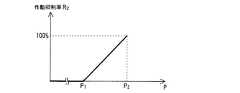
[2.3.3 タンク内の圧力に応じた作動抑制率]
図5に示すように、ブレーキECU1は、負圧Pが、所定負圧P1未満であれば第一ポンプ制御を実施し、所定負圧P1以上であれば第二ポンプ制御を実施する。
この第二ポンプ制御では、負圧Pが所定負圧P1以上の範囲で所定負圧P1よりも大きくなるに従って、ポンプ50の作動抑制率R2を大きくし、負圧Pが所定負圧P2になるとポンプ50を停止(作動抑制率100%)させる。なお、作動抑制率R2は、実線で示すように線形に変化するものに限らない。[2.3.3 Operation suppression rate according to the pressure in the tank]
As shown in FIG. 5, the brake ECU1 is negative pressure P is carried out first pump control is less than a predetermined negative pressure P1, to implement the second pump control if a predetermined negative pressure P1 or more.
In the second pump control, according to the negative pressure P is greater than the predetermined negative pressure P1 at a predetermined negative pressure P1 or more ranges, by increasing the operation inhibition rate R2 of the
[2.3.4 各作動抑制率及び低減係数の扱い]
第二ポンプ制御では、上記の作動抑制率R1及びR2並びに低減係数αを、以下のように組み合わせて用いる。
ブレーキECU1は、ブロアファン71の回転数にかかる作動抑制率R1にモータ80の回生量にかかる低減係数αを乗算する。この作動抑制率に、圧力Pにかかる作動抑制率R2を乗算して、最終的なポンプ50の作動抑制率Rを決定する。そして、ブレーキECU1は、最大回転数に作動抑制率Rを乗算した回転数となるようにポンプ50の回転数を制御することで、ポンプ50の作動を抑える。[2.3.4 Handling of each operation suppression rate and reduction factor]
In the second pump control, the operation suppression rates R1 and R2 and the reduction coefficient α are used in combination as follows.
The brake ECU 1 multiplies the operation suppression rate R1 related to the rotation speed of the
例えば、ブロアファン71の回転数が高く(空調装置70の発生音が大きい)、モータ80の回生量が小さい(モータ80の回生音が小さい)ときには、作動抑制率R1は小さい又はゼロであり、低減係数αは大きい。この場合にポンプ制御に用いる作動抑制率Rは、小さい作動抑制率R1に大きい低減係数αを乗算したものであり、ポンプ50の作動は略抑制されない。For example, when the rotational speed of the
[3 作用・効果]
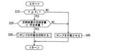
本発明の一実施形態に係る車両の負圧ポンプ制御装置は上述のように構成されるため、ブレーキECU1により、所定の制御周期毎に図6に示すフローが行なわれる。このフローは、モータ80による単体走行時に、ブレーキスイッチ11がONからOFFに変化すると開始される。[3 Actions and effects]
Since the negative pressure pump control device for a vehicle according to one embodiment of the present invention is configured as described above, the flow shown in FIG. 6 is performed by the brake ECU 1 every predetermined control cycle. This flow is started when the
ステップS10では、負圧Pが所定負圧P1以上であるか否かを判定する。負圧Pが、所定負圧P1以上であればステップS20へ移行し、所定負圧P1未満であればステップS40へ移行する。
ステップS20では、空調装置70の空調音量が所定音量未満であるか否かを判定する。空調装置70の空調音量が、所定音量未満であればステップS30へ移行し、所定音量以上であればステップS40へ移行する。
ステップS30では、ポンプ50の作動を抑制する。図7を用いて、ステップS30で実施されるサブルーチンの一例を説明する。In step S10, the negative pressure P is equal to or a predetermined negative pressure P1 or more. Negative pressure P is, the process proceeds to step S20 if the predetermined negative pressure P1 or more, the process proceeds to step S40 if it is less than the predetermined negative pressure P1.
In step S20, it is determined whether the air conditioning volume of the
In step S30, the operation of the
ステップS32では、ブロアファン71の回転数にかかる作動抑制率R1に、モータ80の回生量rにかかる低減係数αと、負圧Pにかかる作動抑制率R2とを乗算し、ポンプ制御に用いる作動抑制率Rを決定し、この抑制率Rを用いてポンプ50の作動を抑制する。そして、図6のリターンへ移行し、本制御周期を終了する。
また、図6のステップS40では、ポンプ50を作動させる。このポンプ50の作動は、ポンプ50を最大回転数にすることである。そして、本制御周期を終了(リターン)する。In step S32, the operation inhibition rate R1 according to the rotational speed of the
In step S40 of FIG. 6, the
したがって、本実施形態の車両の負圧ポンプ制御装置によれば、負圧Pがブレーキブースタ20によりブレーキ踏力を十分にアシストすることのできる負圧である所定負圧P1以上であって、空調装置70で発生する空調音量がポンプ50の作動音よりも小さければ、ブレーキECU1はポンプ50の作動を抑制する。このため、ポンプ50の作動を抑制してもブレーキ力は確保されつつ、ポンプ50の作動音量が小さくなり、ポンプ50の作動音量は空調装置70の空調音量に近づく或いは下回る。よって、車両の制動性能と静音性能との均衡を図ることができる。さらに、ブレーキ力を確保しつつ、空調装置70の発生音によってポンプ50の作動音をマスクする(紛らわす)ことにより、ポンプ50の作動音の際立ちを抑制することができ、延いては、車両乗員の居住性を向上させることができる。Therefore, according to the vacuum pump control apparatus for a vehicle of the present embodiment, the negative pressure P is not more predetermined negative pressure P1 or more is a negative pressure capable of assisting the brake pedal force sufficiently by the
空調装置70は車両乗員の操作により作動するため、空調音は、乗員にとって不快な音ではないといえる。一方、ポンプ50は乗員の意思とは関係なく作動するため、その作動音は、乗員にとって不快な音と考えられる。かかるポンプ50の作動音を、本発明の負圧ポンプ制御装置は、空調装置70の空調音によりマスクすることにより、ポンプ50の発生音の際立ちを抑制することができる。 Since the
走行時のモータ80の発生音は、主に高周波成分の微弱な音であり、乗員にとって不快な音ではないと考えられる。一方、回生時のモータ80の発生音は、高周波成分に低周波成分を含むため、乗員にとって不快な音と考えられる。かかる回生時のモータ80の発生音量が大きくなるに従って、ポンプ50の作動抑制率を低減するため、モータ80の回生音にポンプ50の作動音がマスクされ、ポンプ50の作動をの際立ちを効果的に抑制することができる。延いては、モータ80の回生音の際立ちをも抑制することができる。 The sound generated by the
ブレーキECU1は、負圧センサ60で検出された負圧Pが所定負圧P1以上の範囲で所定負圧P1よりも大きくなるに従って、ポンプ50の作動抑制率R2を大きくするため、ブレーキ力が十分に確保されたときに、更にブレーキ力を確保するとともに、ポンプ50の作動音を小さくすることにより、かかるポンプ50の作動音の際立ちを更に抑制することができる。
ブレーキECU1は、負圧Pが所定負圧P1未満であれば、ポンプ50を作動させるため、負圧Pを速やかに所定負圧P1以上に上昇して、十分にブレーキ力を確保することができる。
ブレーキECU1は、ポンプ50の作動を抑制する第二ポンプ制御では、ポンプ50の回転数を低下させるため、回転数制御という汎用の制御ロジックで、ポンプ50の作動を抑えることができる。Brake ECU1, since the negative pressure P detected by the
When the negative pressure P is less than the predetermined negative pressure P1 , the brake ECU 1 operates the
In the second pump control that suppresses the operation of the
ブレーキECU1は、空調装置70の作動状態のレベルが小に変更された際は空調装置70の作動状態のレベルが中又は大に変更された際に比べて、ポンプ50の作動を抑制するため、三段階の風量調整が可能な一般的な空調装置において、ポンプ50の作動音のレベルは空調装置70の空調音量に近づく或いは下回る。このため、ポンプ50の作動音の際立ちを抑制することができる。 The brake ECU 1 suppresses the operation of the
[4 その他]
以上、本発明の実施形態について説明したが、本発明は上述の実施形態に限定されるものではなく、本発明の趣旨を逸脱しない範囲で種々変形して実施することができる。
上述の実施形態では、負圧Pが所定負圧P1以上であることを条件にポンプの作動を抑制するものを示したが、負圧Pが所定負圧P1以上である条件は必須ではなく、ブレーキECUは、少なくとも空調装置の作動状態に基づいてポンプの作動を制御すればよい。この場合、例えば、ブレーキECUは、空調装置が作動していればポンプの作動を抑制する。[4 Others]
Although the embodiments of the present invention have been described above, the present invention is not limited to the above-described embodiments, and various modifications can be made without departing from the spirit of the present invention.
In the above embodiment, the negative pressure P showed that suppress the operation of the pump on condition that the predetermined negative pressure P1 or more, conditions negative pressure P is a predetermined negative pressure P1 or more essential Instead, the brake ECU may control the operation of the pump based on at least the operating state of the air conditioner. In this case, for example, the brake ECU suppresses the operation of the pump if the air conditioner is operating.
また、モータの単体走行時に、ブレーキスイッチがONからOFFに変化すればポンプ制御を開始するものを説明したが、これに限らず、ブレーキECUは、モータ単体走行時にブレーキスイッチがOFFであればポンプ制御を開始してもよく、また、単にモータにより車両を駆動して走行している際にポンプ制御を開始してもよい。 In addition, although the pump control is started when the brake switch is changed from ON to OFF when the motor is traveling alone, the brake ECU is not limited to this. Control may be started, or pump control may be started when the vehicle is simply driven by a motor.
また、空調装置については、空調装置の空調音としてロアファンの発生音に着目したものを説明したが、これに限らず、空調装置の冷媒を圧縮するコンプレッサの発生音に着目してもよい。この場合、コンプレッサの発生音が、所定音量以上であれば第一ポンプ制御を実施し、所定音量未満であれば第二ポンプ制御を実施する。 In addition, the air conditioner has been described as focusing on the sound generated by the lower fan as the air conditioning sound of the air conditioner, but is not limited thereto, and may be focused on the sound generated by the compressor that compresses the refrigerant of the air conditioner. In this case, if the generated sound of the compressor is equal to or higher than a predetermined volume, the first pump control is performed, and if it is less than the predetermined volume, the second pump control is performed.
また、モータが回生作動している際に、モータの回生量が大きくなるに従ってポンプの作動抑制率の低減度合い大きくするものを示したが、これに限らず、ポンプの作動が抑制されているときにモータが回生作動していれば、ポンプの作動抑制率を一律に低減してもよい。
また、ポンプの作動抑制率の低減は、モータが回生作動している際に限らず、例えばオーディオ装置が作動している際に行ってもよい。In addition, when the motor is in regenerative operation, the reduction rate of the pump operation suppression rate increases as the motor regeneration amount increases, but this is not limiting, and when the pump operation is suppressed If the motor is regeneratively operated, the pump operation suppression rate may be reduced uniformly.
Further, the reduction of the pump operation suppression rate is not limited to when the motor is regeneratively operated, but may be performed, for example, when the audio device is operating.
上述の実施形態では、空調装置の作動状態のレベルが大中小の三段階に設定されたものを例に、作動状態が中のレベルの空調装置における空調音量は、ポンプの作動音量である所定音量よりも小さい空調音を発生させるものを示したが、これに限らず、中のレベルに相当する空調音量が所定音量よりも大きく、小のレベルに相当する空調音量が所定音量よりも小さい空調装置を用いてもよい。また、空調装置には、空調操作により、作動状態のレベルが連続的に設定されるものを用いてもよく、大小の異なる複数の作動状態が段階的に設定されるものを用いてもよい。 In the above-described embodiment, the air conditioning volume in the air conditioner in the medium operating state is the predetermined volume that is the pump operating volume, for example, in which the air conditioner operating state level is set to three levels of large, medium, and small However, the present invention is not limited to this, but the air conditioning volume corresponding to the medium level is larger than the predetermined volume, and the air conditioning volume corresponding to the lower level is smaller than the predetermined volume. May be used. In addition, the air conditioner may be one in which the operating state level is continuously set by the air conditioning operation, or may be one in which a plurality of different operating states are set in stages.
上述の実施形態では、ポンプ制御では、空調装置の空調音が、所定音量以上であれば第一ポンプ制御を実施し、所定音量未満であれば第二ポンプ制御を実施するものを示したが、これに限らず、空調装置が作動していれば(空調音が発生していれば)第一ポンプ制御を実施し、空調装置が停止していれば(空調音が発生していなければ)第二ポンプ制御を実施してもよい。
また、ブレーキブースタがタンクを有するものを示したが、タンクは無くてもよい。この場合、ブースタシリンダの負圧室が圧力を蓄える蓄圧器として機能する。In the above-described embodiment, in the pump control, the first pump control is performed if the air-conditioning sound of the air conditioner is equal to or higher than the predetermined volume, and the second pump control is performed if it is lower than the predetermined volume. Not limited to this, the first pump control is performed if the air conditioner is operating (if the air conditioner sound is generated), and the first pump control is performed if the air conditioner is stopped (if the air conditioner sound is not generated). Dual pump control may be implemented.
Further, although the brake booster has a tank, the tank may be omitted. In this case, the negative pressure chamber of the booster cylinder functions as a pressure accumulator that stores pressure.
また、ポンプは、負圧室に負圧を供給するバキュームポンプを用いたが、これに限らず、空気室に正圧を供給する加圧ポンプを用いてもよい。この場合、図8に示すようなブレーキブースタ200を用いる。このブレーキブースタ200では、正圧室270Bには正圧を供給する加圧ポンプ500が接続され、空気室270Aには空気(大気)が流入される。 Moreover, although the vacuum pump which supplies a negative pressure to a negative pressure chamber was used for the pump, not only this but the pressurization pump which supplies a positive pressure to an air chamber may be used. In this case, a
また、ブレーキブースタに圧力を発生させるポンプには、吐出容量可変型のポンプを用いてもよい。この場合、ポンプの作動を抑えるときには、吐出容量を低下させる或いは回転数を低下させる。この吐出容量可変型のポンプは、吐出容量が低下すると、同回転数であっても発生音量が低下する。このため、該ポンプの発生音量が低下する。 Further, a variable discharge capacity type pump may be used as a pump for generating pressure in the brake booster. In this case, when suppressing the operation of the pump, the discharge capacity is reduced or the rotational speed is reduced. In the discharge capacity variable type pump, when the discharge capacity decreases, the generated sound volume decreases even at the same rotation speed. For this reason, the volume generated by the pump decreases.
また、大気圧とタンク内の気圧との差圧、即ち負圧を検出する負圧センサを示したが、これに限らず、タンク内の気圧そのものを検出する圧力センサを用いてもよい。この場合、ブレーキECUは、圧力センサで検出された気圧を大気圧から減算する演算を行ない、この演算結果を負圧Pとして用いる。この場合、圧力センサ及びブレーキECUが負圧検出手段を構成する。
また、制御条件(2)にかかる空調装置で発生する音量は、車室内に伝達された音量に限らず、空調装置の配設箇所の音量を用いてもよい。同様に、所定音量についても、ポンプの配設箇所における作動音量を用いてもよい。Moreover, although the negative pressure sensor which detects the differential pressure | voltage between atmospheric pressure and the atmospheric pressure in a tank, ie, a negative pressure, was shown, you may use not only this but the pressure sensor which detects the atmospheric pressure itself in a tank. In this case, the brake ECU performs a calculation for subtracting the atmospheric pressure detected by the pressure sensor from the atmospheric pressure, and uses the calculation result as the negative pressure P. In this case, the pressure sensor and the brake ECU constitute negative pressure detecting means.
Further, the volume generated by the air conditioner according to the control condition (2) is not limited to the volume transmitted to the passenger compartment, and the volume at the location where the air conditioner is disposed may be used. Similarly, for the predetermined volume, the operating volume at the location where the pump is disposed may be used.
また、ブレーキ装置にかかる負圧は気圧にかかるものを示したが、これに限らず、油圧を用いてブレーキ装置の動作力をアシストする油圧(ハイドロ)ブレーキブースタを用いてもよい。この場合、空気を吸引するポンプに替えて、油圧を発生させる油圧ポンプを用い、バキュームタンクに替えて油圧を蓄圧する蓄圧器を用いる。 In addition, although the negative pressure applied to the brake device has been shown to be applied to the atmospheric pressure, the present invention is not limited to this, and a hydraulic (hydro) brake booster that assists the operating force of the brake device using hydraulic pressure may be used. In this case, a hydraulic pump that generates hydraulic pressure is used instead of the pump that sucks air, and a pressure accumulator that accumulates hydraulic pressure is used instead of the vacuum tank.
また、ブレーキ装置の動作力としてブレーキ踏力を示したが、ブレーキ装置を動作させるための運転者による入力であればこれに限らず、例えば、ブレーキ装置の動作力は、下肢障害者等によるハンドブレーキ操作力でもよい。 In addition, although the brake pedaling force is shown as the operating force of the brake device, the operating force of the brake device is not limited to this as long as it is input by the driver for operating the brake device. Operation force may be used.
本発明の車両の負圧ポンプ制御装置は、ブレーキブースタに負圧を発生させる負圧ポンプを搭載した自動車に有効であるほか、かかる負圧ポンプを搭載した、自動車をはじめとする種々の車両に用いることができる。 The vehicle negative pressure pump control device according to the present invention is effective for a vehicle equipped with a negative pressure pump that generates a negative pressure in a brake booster, and also for various vehicles including the vehicle equipped with such a negative pressure pump. Can be used.
1 ブレーキECU(負圧ポンプ制御手段)
10 ブレーキペダル
11 ブレーキスイッチ
20 ブレーキブースタ
21 バルブオペレーティングロッド
22 バルブプランジャ
23 ブースタピストン
24 プッシュロッド
25 バルブボデー
25A エアバルブ
25B バキュームバルブ
26 流入路
27 ブースタシリンダ
27A 負圧室
27B 空気室
28 連通路
29 タンク
29A インレットマニホールド
30 マスタシリンダ
40 ディスクブレーキ
50 ポンプ(負圧ポンプ)
60 負圧センサ(負圧検出手段)
70 空調装置
71 ブロアファン
80 モータ(走行用モータ)1 Brake ECU (negative pressure pump control means)
DESCRIPTION OF
60 Negative pressure sensor (negative pressure detection means)
70
Claims (5)
Translated fromJapaneseブレーキ装置の動作力をアシストするブレーキブースタに負圧を発生させる負圧ポンプと、
前記車両の室内を空調し、空調音を発生させる空調装置と、
前記走行用モータにより前記車両を駆動して走行している際に、前記空調装置の作動状態に基づいて前記負圧ポンプの作動を制御する負圧ポンプ制御手段と、を備えた
ことを特徴とする、車両の負圧ポンプ制御装置。A traveling motor for traveling the vehicle;
A negative pressure pump that generates negative pressure in a brake booster that assists the operating force of the brake device;
An air conditioner that air-conditions the interior of the vehicle and generates air-conditioning sound;
A negative pressure pump control means for controlling the operation of the negative pressure pump based on the operating state of the air conditioner when the vehicle is driven by the driving motor. A negative pressure pump control device for a vehicle.
前記空調装置で発生する空調音が所定レベル未満を示す作動状態の際は空調音のレベルが前記所定レベル以上を示す作動状態の際に比べて、前記負圧ポンプの作動を抑制する
ことを特徴とする、請求項1記載の車両の負圧ポンプ制御装置。The negative pressure pump control means includes
The operation of the negative pressure pump is suppressed when the air-conditioning sound generated by the air-conditioning apparatus is in an operating state in which the air-conditioning sound is less than a predetermined level compared to in the operating state in which the air-conditioning sound level is higher than the predetermined level. The negative pressure pump control device for a vehicle according to claim 1.
前記負圧ポンプ制御手段は、
前記負圧検出手段で検出された前記ブレーキブースタの負圧が、前記所定負圧以上の範囲で大きくなるに従って、前記負圧ポンプの作動抑制率を高める
ことを特徴とする、請求項2記載の車両の負圧ポンプ制御装置。A negative pressure detecting means for detecting a negative pressure of the brake booster;
The negative pressure pump control means includes
The operation suppression rate of the negative pressure pump is increased as the negative pressure of the brake booster detected by the negative pressure detecting means increases in a range equal to or higher than the predetermined negative pressure. Vehicle negative pressure pump control device.
前記所定レベルは、前記中のレベルに相当するものである
ことを特徴とする、請求項2又は3記載の車両の負圧ポンプ制御装置。The air conditioner has three levels of operating states, small, medium and large,
4. The negative pressure pump control device for a vehicle according to claim 2, wherein the predetermined level corresponds to the medium level.
前記負圧ポンプ制御手段は、前記走行用モータが回生作動している際は、前記負圧ポンプの作動抑制率を低減する
ことを特徴とする、請求項2乃至4の何れか1項に記載の車両の負圧ポンプ制御装置。The traveling motor is regeneratively operated when the vehicle is decelerated,
5. The negative pressure pump control unit according to claim 2, wherein the negative pressure pump control unit reduces an operation suppression rate of the negative pressure pump when the traveling motor is performing a regenerative operation. 6. Vehicle negative pressure pump control device.
Priority Applications (1)
| Application Number | Priority Date | Filing Date | Title |
|---|---|---|---|
| JP2012111400AJP5970949B2 (en) | 2012-05-15 | 2012-05-15 | Vehicle negative pressure pump control device |
Applications Claiming Priority (1)
| Application Number | Priority Date | Filing Date | Title |
|---|---|---|---|
| JP2012111400AJP5970949B2 (en) | 2012-05-15 | 2012-05-15 | Vehicle negative pressure pump control device |
Publications (2)
| Publication Number | Publication Date |
|---|---|
| JP2013237348Atrue JP2013237348A (en) | 2013-11-28 |
| JP5970949B2 JP5970949B2 (en) | 2016-08-17 |
Family
ID=49762781
Family Applications (1)
| Application Number | Title | Priority Date | Filing Date |
|---|---|---|---|
| JP2012111400AExpired - Fee RelatedJP5970949B2 (en) | 2012-05-15 | 2012-05-15 | Vehicle negative pressure pump control device |
Country Status (1)
| Country | Link |
|---|---|
| JP (1) | JP5970949B2 (en) |
Cited By (1)
| Publication number | Priority date | Publication date | Assignee | Title |
|---|---|---|---|---|
| JP2019018661A (en)* | 2017-07-13 | 2019-02-07 | 株式会社デンソーテン | Deposit removal device and deposit removal method |
Citations (3)
| Publication number | Priority date | Publication date | Assignee | Title |
|---|---|---|---|---|
| JP2008018883A (en)* | 2006-07-14 | 2008-01-31 | Mazda Motor Corp | Brake control system of hybrid vehicle |
| JP2009257284A (en)* | 2008-04-21 | 2009-11-05 | Nabtesco Corp | Vacuum pump |
| JP2011042194A (en)* | 2009-08-19 | 2011-03-03 | Nissan Motor Co Ltd | Brake device and brake method for vehicle |
- 2012
- 2012-05-15JPJP2012111400Apatent/JP5970949B2/ennot_activeExpired - Fee Related
Patent Citations (3)
| Publication number | Priority date | Publication date | Assignee | Title |
|---|---|---|---|---|
| JP2008018883A (en)* | 2006-07-14 | 2008-01-31 | Mazda Motor Corp | Brake control system of hybrid vehicle |
| JP2009257284A (en)* | 2008-04-21 | 2009-11-05 | Nabtesco Corp | Vacuum pump |
| JP2011042194A (en)* | 2009-08-19 | 2011-03-03 | Nissan Motor Co Ltd | Brake device and brake method for vehicle |
Cited By (1)
| Publication number | Priority date | Publication date | Assignee | Title |
|---|---|---|---|---|
| JP2019018661A (en)* | 2017-07-13 | 2019-02-07 | 株式会社デンソーテン | Deposit removal device and deposit removal method |
Also Published As
| Publication number | Publication date |
|---|---|
| JP5970949B2 (en) | 2016-08-17 |
Similar Documents
| Publication | Publication Date | Title |
|---|---|---|
| JP5736705B2 (en) | Vehicle control apparatus and vehicle control method | |
| CN102548814B (en) | vehicle control device | |
| JP5962608B2 (en) | Vehicle braking system | |
| JP5781854B2 (en) | Vehicle control device | |
| JP5659580B2 (en) | Vehicle control apparatus and vehicle control method | |
| JP5787050B2 (en) | Vehicle control device | |
| JP5970949B2 (en) | Vehicle negative pressure pump control device | |
| JPH10310041A (en) | Braking force control device | |
| JP6536610B2 (en) | Vehicle braking control device | |
| JPH10264793A (en) | Braking system with regenerative braking for electric vehicles | |
| CN110315989B (en) | Brake device and brake control method for vehicle | |
| JP6354692B2 (en) | Brake control device for vehicle | |
| JP5039125B2 (en) | Vacuum assist pump system | |
| JP5929407B2 (en) | Brake control device for vehicle | |
| JP2012035724A (en) | Air conditioner controller of vehicle | |
| JP2013141339A (en) | Regenerative controller | |
| JP3887852B2 (en) | Brake control device | |
| JP2017217976A (en) | Air suspension device of vehicle | |
| JP5939467B2 (en) | Vehicle pressure accumulation system | |
| WO2015046460A1 (en) | Vehicle braking system | |
| JP2013141338A (en) | Braking device for vehicle | |
| JP5799741B2 (en) | Brake control device | |
| JP2012101773A (en) | Control device for electric negative pressure pump | |
| JP2018065495A (en) | Braking control device of vehicle | |
| JP5765180B2 (en) | Brake control device |
Legal Events
| Date | Code | Title | Description |
|---|---|---|---|
| A621 | Written request for application examination | Free format text:JAPANESE INTERMEDIATE CODE: A621 Effective date:20150424 | |
| A977 | Report on retrieval | Free format text:JAPANESE INTERMEDIATE CODE: A971007 Effective date:20160212 | |
| A131 | Notification of reasons for refusal | Free format text:JAPANESE INTERMEDIATE CODE: A131 Effective date:20160329 | |
| A521 | Request for written amendment filed | Free format text:JAPANESE INTERMEDIATE CODE: A523 Effective date:20160524 | |
| TRDD | Decision of grant or rejection written | ||
| A01 | Written decision to grant a patent or to grant a registration (utility model) | Free format text:JAPANESE INTERMEDIATE CODE: A01 Effective date:20160614 | |
| A61 | First payment of annual fees (during grant procedure) | Free format text:JAPANESE INTERMEDIATE CODE: A61 Effective date:20160627 | |
| R151 | Written notification of patent or utility model registration | Ref document number:5970949 Country of ref document:JP Free format text:JAPANESE INTERMEDIATE CODE: R151 | |
| LAPS | Cancellation because of no payment of annual fees |