JP2013236811A - Valve element for connector, and the connector - Google Patents
Valve element for connector, and the connectorDownload PDFInfo
- Publication number
- JP2013236811A JP2013236811AJP2012112651AJP2012112651AJP2013236811AJP 2013236811 AJP2013236811 AJP 2013236811AJP 2012112651 AJP2012112651 AJP 2012112651AJP 2012112651 AJP2012112651 AJP 2012112651AJP 2013236811 AJP2013236811 AJP 2013236811A
- Authority
- JP
- Japan
- Prior art keywords
- valve body
- connector
- head
- connection port
- radial support
- Prior art date
- Legal status (The legal status is an assumption and is not a legal conclusion. Google has not performed a legal analysis and makes no representation as to the accuracy of the status listed.)
- Granted
Links
Images


Landscapes
- Quick-Acting Or Multi-Walled Pipe Joints (AREA)
- Medical Preparation Storing Or Oral Administration Devices (AREA)
- Infusion, Injection, And Reservoir Apparatuses (AREA)
Abstract
Translated fromJapaneseDescription
Translated fromJapaneseこの発明は、コネクタ用弁体及びコネクタに関し、さらに詳しくは、シール性の高い密閉状態から開放状態に容易に移行し、かつ元の密閉状態に復元移行するコネクタ及びこのコネクタに用いられるコネクタ用弁体に関する。 The present invention relates to a valve body for a connector and a connector, and more particularly, a connector that easily shifts from a sealed state having a high sealing property to an open state and restores the original sealed state, and a connector valve used in the connector About the body.
少なくとも2つの管体同士を接続するコネクタには種々のものが知られており、例えば、医療用コネクタが挙げられる。医療用コネクタは、例えば、患者に留置されたカテーテル等を介して患者に必要な薬液、体液、栄養剤等(この発明において流体と称する。)を投与する静脈内投与又は輸血等に用いられるコネクタ、1つの管体に接続された第1の流体とは異なる種類又は濃度の第2の流体を同様にして患者に静脈内投与する場合に用いられるコネクタ、具体的には混注管等が挙げられる。 Various connectors for connecting at least two tube bodies are known, and examples thereof include medical connectors. The medical connector is, for example, a connector used for intravenous administration, blood transfusion, or the like for administering a medical solution, a body fluid, a nutrient, or the like (referred to as a fluid in this invention) necessary for a patient via a catheter or the like placed in the patient. A connector used when intravenously administering a second fluid of a type or concentration different from the first fluid connected to one tube body to the patient in a similar manner, specifically, a mixed injection tube or the like. .
従来、混注管等の医療用コネクタに第2の流体を注入するのに注射針を備えた注射器等を用いていたが、医療従事者の針刺しによる感染を未然に回避するために、近年、このような注射器に代えて、注射針を備えていない注射器等の管体、例えば、ルアーロック付きシリンジ、ルアーロック付き輸液管等が医療用コネクタに接続する管体として用いられるようになっている。 Conventionally, a syringe equipped with an injection needle has been used to inject the second fluid into a medical connector such as a mixed injection tube. However, in order to avoid infection due to needle stick of a medical worker, Instead of such a syringe, a tube body such as a syringe that does not include an injection needle, for example, a syringe with a luer lock, an infusion tube with a luer lock, and the like are used as a tube body connected to a medical connector.
このような注射針を備えていない管体を接続可能又は使用可能な医療用コネクタは、接続口を常時液密にシールする一方、必要時に限って接続口を開いて流体を投与可能にするために、その内部にコネクタ用弁体を備えている。 Such a medical connector that can connect or use a tube body that does not have an injection needle seals the connection port in a liquid-tight manner at all times, while opening the connection port only when necessary so that fluid can be administered. In addition, a connector valve body is provided therein.
このような医療用コネクタとして、例えば、特許文献1には「雄ルアーが分離可能に接続される医療用弁であって、上下両端が開口する中空状のハウジングと、弾性変形可能な弾性シールを有し、ハウジングは、ハウジングの上部を構成する本体と、ハウジングの下部を構成し且つ本体の下端部に接続された接続体を有し、本体内の上部が、雄ルアーのチップが挿脱自在に挿入される接続口とされ、本体内における、接続口の下方に、下方に向かうに従って内径が大となる拡大部が設けられ、接続体の上端部は、A.接続口の真下に位置する部分と、B.接続口の真下からずれた位置に形成され、拡大部内部と接続体内部を連通させる貫通孔を有し、弾性シールは、イ.その上部を構成し、接続口内に嵌合されると共に、上端面に、上方及び径方向外方に開口する液体移送路が形成された封止部と、ロ.封止部の下方に配設され、下方に向かうに従って、外径及び内径が大となる中空状とされて、下端で開口すると共に、拡大部に対して開口する通過孔が貫通形成され、拡大部に対向する全面において拡大部内面と密着するように拡大部内に嵌合されて、拡大部を閉鎖する膜部を有し、雄ルアーのチップにより、弾性シールの封止部が下方に押圧されて、弾性シールの膜部が下方に弾性変形し、膜部における、通過孔を含む上部側が拡大部から離間して、封止部の液体移送路が、拡大部の内部及び通過孔を介して、膜部の内部と連通する医療用弁」が記載されている(請求項1)。 As such a medical connector, for example, Patent Document 1 discloses a “medical valve to which a male luer is detachably connected, a hollow housing having upper and lower ends open, and an elastically deformable elastic seal. The housing has a main body that constitutes the upper part of the housing and a connecting body that constitutes the lower part of the housing and is connected to the lower end of the main body. An enlarged portion having an inner diameter that increases toward the bottom is provided below the connection port in the main body, and the upper end of the connection body is located directly below the A. connection port. B. Formed at a position shifted from directly below the B. connection port, and has a through hole that allows the inside of the enlarged portion and the inside of the connection body to communicate with each other, and the elastic seal constitutes the upper part of the connection and fits in the connection port At the upper end surface, and A sealing portion formed with a liquid transfer path that opens outward in the direction, b) a hollow portion having an outer diameter and an inner diameter that increase toward the lower side, And a passage hole that opens to the enlarged portion is formed so as to be in close contact with the inner surface of the enlarged portion on the entire surface facing the enlarged portion, and a membrane portion that closes the enlarged portion is formed. And the male luer tip presses the sealing part of the elastic seal downward, the elastic sealing film part is elastically deformed downward, and the upper side of the film part including the passage hole is separated from the enlarged part. The medical valve in which the liquid transfer path of the sealing portion communicates with the inside of the membrane portion via the inside of the enlarged portion and the passage hole is described (Claim 1).
また、特許文献2及び特許文献3には、概略、「物質を収納する空間22を有する本体12と、キャップアセンブリ14と、バルブアセンブリ16とを備えたバイアル10であって、前記バルブアセンブリ16は、外周に第1環状シール面30、第2環状シール面36及び環状突起32を有し、頂面に互いに離間する複数の突起56を有する上部29と、環状シール面44、ドーム状又は球状のスプリング48、中空円筒部52及び開口54を有するベース部40とを有するバイアル10」が記載されている(特許文献2の第5欄〜第13欄及び第1図〜第9図並びに特許文献3の第6欄〜第13欄及び第1図〜第9図)。 Patent Document 2 and Patent Document 3 generally describe a vial 10 including a
さらに、特許文献4には、概略、「キャップ14及び本体16を有するハウジング10と、軸孔にピン24が内装され、先端近傍の周面にワイパーシール25を有する可動ピストン18と、前記ピストン18に一体的に形成されて付勢する、数個の貫通孔を有する略円形の伸縮性エレメント20とを備えた針無しアクセス装置10」が記載されている(第2欄〜第3欄及び欄第1図〜第7図)。 Further, Patent Document 4 generally describes “a housing 10 having a
このような医療用コネクタをはじめ各種のコネクタは、その内部に収納されたコネクタ用弁体が密閉状態から開放状態に容易に移行することに加えて開放状態から初期の密閉状態に復元することが所期の機能を発揮するうえで重要になる。 Various connectors including such medical connectors can be restored from the open state to the initial sealed state in addition to the connector valve body housed therein being easily shifted from the sealed state to the open state. It becomes important to demonstrate the intended function.
この発明は、シール性の高い密閉状態から開放状態に容易に移行し、かつ元の密閉状態に復元移行するコネクタ、及び、このコネクタに用いられるコネクタ用弁体を提供すること、を目的とする。 An object of the present invention is to provide a connector that easily shifts from a sealed state having a high sealing property to an open state and restores and restores the original sealed state, and a connector valve body used in the connector. .
前記課題を解決するための第1の手段である、この発明に係るコネクタ用弁体は、管体を接続可能な少なくとも2つの接続口、これらの接続口を連通する流路、及び、第1の前記接続口の近傍に配置された弁体保持部を有するコネクタ管に収納され、流体の流通を制御するコネクタ用弁体であって、一端部近傍に環状に突設され、前記第1の接続口の内周面に密接する環状シール部及び頂面に突設された突条を有する小径部、並びに、前記小径部の他端部に連設された大径部を有する中実頭部と、前記大径部の自由端から周方向に間隔をあけて略水平方向に放射状に延在する複数の輻状支持脚、及び、周方向に隣接する前記輻状支持脚の間に配置され、前記大径部の外周面から前記輻状支持脚の先端まで広がる複数の空隙部を有する頭部支持部とを備えていることを特徴とする。 The valve body for a connector according to the present invention, which is a first means for solving the above-mentioned problems, includes at least two connection ports that can connect a tube, a flow path that connects these connection ports, and a first A connector valve body that controls the flow of fluid and is housed in a connector pipe having a valve body holding portion disposed in the vicinity of the connection port, and is annularly projected in the vicinity of one end portion. A solid head having an annular seal portion that is in close contact with the inner peripheral surface of the connection port, a small-diameter portion having a protrusion protruding from the top surface, and a large-diameter portion that is connected to the other end of the small-diameter portion. And a plurality of radial support legs extending radially from the free end of the large-diameter portion in the circumferential direction and spaced radially, and the radial support legs adjacent to each other in the circumferential direction. The head support having a plurality of gaps extending from the outer peripheral surface of the large diameter portion to the tip of the radial support leg Characterized in that it comprises and.
このコネクタ用弁体における好適な一例は、
(1)前記輻状支持脚の先端に配置され、前記弁体保持部に保持される被保持部を有しており、
(2)前記小径部は、前記内周面に非接触となる平坦な外周面を有しており、
(3)前記被保持部は、前記輻状支持脚の先端それぞれを環状に連結する環状被保持部であり、
(4)前記コネクタ用弁体は、弾性材料で作製されている。A preferred example of this connector valve body is:
(1) It is disposed at the tip of the radial support leg and has a held portion that is held by the valve body holding portion.
(2) The small diameter portion has a flat outer peripheral surface that is not in contact with the inner peripheral surface,
(3) The held portion is an annular held portion that connects the distal ends of the radial support legs in an annular shape.
(4) The connector valve body is made of an elastic material.
前記課題を解決するための第2の手段である、この発明に係るコネクタは、管体を接続可能な少なくとも2つの接続口、これらの接続口を連通する流路、及び、第1の前記接続口の近傍に配置された弁体保持部を有するコネクタ管と、前記弁体保持部に収納され、前記小径部の少なくとも一部が前記第1の前記接続口内に配置されたこの発明に係るコネクタ用弁体とを備えていることを特徴とする。 The connector according to the present invention, which is a second means for solving the above-described problems, includes at least two connection ports to which a tubular body can be connected, a flow path communicating these connection ports, and the first connection. A connector pipe having a valve body holding portion disposed in the vicinity of the mouth, and a connector according to the present invention housed in the valve body holding portion, wherein at least a part of the small diameter portion is disposed in the first connection port. And a valve body for use.
このコネクタにおける好適な一例は、
(1)前記コネクタ用弁体は、前記中実頭部で前記第1の接続口を密閉する密閉状態と、その軸線方向に作用する圧力で前記密閉が解除される開放状態とに移行可能であり、
(2)前記コネクタ管は、3つ以上の前記接続口を有する混注管である。A suitable example of this connector is
(1) The connector valve body can be shifted between a sealed state in which the first connection port is sealed with the solid head and an open state in which the sealing is released by pressure acting in the axial direction. Yes,
(2) The connector pipe is a mixed injection pipe having three or more connection ports.
この発明に係るコネクタ用弁体は、一端部近傍に環状に突設され、コネクタ管における第1の接続口の内周面に密接する環状シール部及び頂面に突設された突条を有する小径部、並びに、小径部の他端部に連設された大径部を有する中実頭部と、大径部の自由端から周方向に間隔をあけて略水平方向に放射状に延在する複数の輻状支持脚、及び、周方向に隣接する輻状支持脚の間に配置され、大径部の外周面から輻状支持脚の先端まで広がる複数の空隙部を有する頭部支持部とを備えているから、コネクタ管の弁体収納部に収納されたときに頭部支持部で担持されて第1の接続口内に配置された中実頭部で第1の接続口をシール性よく密閉できる。また、この発明に係るコネクタ用弁体は、このような中実頭部及び頭部支持部を備えているから、コネクタ管の弁体収納部に収納されたときに、横架された頭部支持部で担持された中実頭部に作用する押圧力のほとんどを頭部支持部に伝達して密閉状態から開放状態に容易に移行すると共に、この押圧力の解除によって移行した開放状態から移行前の元の密閉状態に復元移行する。また、この発明に係るコネクタはこのコネクタに用いられるコネクタ用弁体を備えている。 The connector valve body according to the present invention has an annular seal portion projecting annularly in the vicinity of one end, an annular seal portion in close contact with the inner peripheral surface of the first connection port in the connector pipe, and a protrusion projecting on the top surface. A solid head having a small-diameter portion and a large-diameter portion connected to the other end of the small-diameter portion, and radially extending from a free end of the large-diameter portion in a circumferential direction with a spacing in the circumferential direction. A plurality of radial support legs, and a head support part that is disposed between the radial support legs adjacent in the circumferential direction and has a plurality of gaps extending from the outer peripheral surface of the large-diameter portion to the distal ends of the radial support legs; Therefore, the first connection port is well sealed with a solid head that is supported by the head support portion and disposed in the first connection port when stored in the valve body storage portion of the connector pipe. Can be sealed. Further, since the connector valve body according to the present invention includes such a solid head and a head support portion, when the connector valve body is stored in the valve body storage portion of the connector pipe, Most of the pressing force acting on the solid head carried by the support part is transmitted to the head support part to easily shift from the sealed state to the open state, and also from the open state that has shifted by releasing this pressing force Restores the previous sealed state. The connector according to the present invention includes a connector valve body used in the connector.
したがって、この発明によれば、シール性の高い密閉状態から開放状態に容易に移行し、かつ元の密閉状態に復元移行するコネクタ及びこのコネクタに用いられるコネクタ用弁体を提供できる。 Therefore, according to the present invention, it is possible to provide a connector that easily shifts from a sealed state having a high sealing property to an open state and restores and restores the original sealed state, and a connector valve body used in the connector.
この発明に係るコネクタ用弁体は、少なくとも2つの管体同士を接続するコネクタ、例えば、患者に留置されたカテーテルに連結されたチューブ等と輸液管等とを接続する医療用コネクタ、特に、前記チューブと、注射針を備えていない注射器等の管体、例えば、ルアーロック付きシリンジ、ルアーロック付き輸液管等(この発明において針無し管体と称する。)とを接続する医療用コネクタに、好適に用いられる。以下に医療用コネクタを例に挙げてこの発明を説明する。 The valve body for a connector according to the present invention is a connector for connecting at least two pipe bodies, for example, a medical connector for connecting a tube connected to a catheter placed in a patient and an infusion pipe, etc. Suitable for a medical connector for connecting a tube and a tube body such as a syringe not provided with an injection needle, for example, a syringe with a luer lock, an infusion tube with a luer lock, etc. (referred to as a needleless tube body in the present invention). Used for. The present invention will be described below by taking a medical connector as an example.
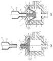
この発明に係るコネクタについての詳細は後述するが、この発明に係るコネクタ用弁体の理解を容易にするため簡単に説明すると、この発明に係るコネクタの好適な一例である医療用コネクタ1は、図6(a)に示されるように、側面視略T字状のコネクタ管4とコネクタ管4に内蔵されるコネクタ用弁体5Aとを備えている。このコネクタ管4は、例えば針無し管体81を接続可能な第1の接続口11、患者に留置されたカテーテル等に連結された、図示しない管体が接続される第2の接続口12、及び、患者に投与する流体を収納したバッグ等に連結された、図示しない管体が接続される第3の接続口13と、これらの接続口11〜13を連通させる内部空間としての流路14と、この内部空間における第1の接続口11の近傍の内周面に凹設配置された弁体保持部15とを有している。コネクタ用弁体5Aはその被保持部23Aが狭圧保持された状態で弁体保持部15に収納される。 Although details of the connector according to the present invention will be described later, in order to facilitate understanding of the connector valve body according to the present invention, a medical connector 1 which is a preferred example of the connector according to the present invention will be described below. As shown in FIG. 6A, a connector tube 4 having a substantially T shape in side view and a connector valve body 5A built in the connector tube 4 are provided. The connector tube 4 includes, for example, a
この発明に係るコネクタ用弁体は、この発明に係るコネクタ、例えばコネクタ1におけるコネクタ管4に設けられた弁体保持部15に狭圧保持された状態でコネクタ管4内に収納配置される。このとき、この発明に係るコネクタ用弁体は、頭部支持部がコネクタ管4の軸線に対して略垂直方向に横架され、この頭部支持部に担持された中実頭部の少なくとも一部が第1の接続口内に配置されている。このように配置されたこの発明に係るコネクタ用弁体は、中実頭部の外周と内部空間の内面と共に流体を流通させる環状の流通路を形成すると共に、流体をこの流通路から第2の接続口13に向けてこの発明に係るコネクタ用弁体の軸線方向に沿って空隙部を通過するように流通させる。 The valve body for a connector according to the present invention is housed and disposed in the connector pipe 4 in a state where the valve
まず、この発明に係るコネクタ用弁体の概要を簡単に説明する。この発明に係るコネクタ用弁体は中実頭部と、中実頭部の軸線に対して略垂直方向に向かって放射状に延在する複数の輻状支持脚及び輻状支持脚の間に配置された複数の空隙部を有する頭部支持部とを有している。そして、中実頭部は、小径部とこの小径部の他端部に連設された大径部とを有しており、小径部は一端部近傍に環状に突設され、コネクタ管4の第1の接続口11の内周面16に密接する環状シール部、及び、頂面に突設され、第1の接続口11から突出する突条を有している。また、頭部支持部は、中実頭部における大径部の自由端から周方向に間隔をあけて中実頭部の軸線に対して略垂直方向に向かって放射状に延在する複数の輻状支持脚と、周方向に隣接する輻状支持脚の間に配置され、大径部の外周面から輻状支持脚の先端まで広がる空隙部とを有している。 First, the outline of the valve body for a connector according to the present invention will be briefly described. A valve body for a connector according to the present invention is disposed between a solid head and a plurality of radial support legs and radial support legs extending radially in a direction substantially perpendicular to the axis of the solid head. And a head support portion having a plurality of gap portions. The solid head has a small-diameter portion and a large-diameter portion connected to the other end portion of the small-diameter portion. An annular seal portion that is in close contact with the inner
この中実頭部は、互いに異なる外径を有する中実の小径部及び中実の大径部を有し、自身に作用する圧力をほとんど損失させることなく頭部支持部に伝達する。したがって、このような中実頭部を備えたこの発明に係るコネクタ用弁体は、コネクタ管4に収納されたときに、中実頭部に作用して中実頭部から伝達された押圧力で頭部支持部が伸張して中実頭部が後退し、密閉状態から開放状態に容易に移行すると共に、押圧力の解除によって中実頭部が前進して開放状態から移行前の元の密閉状態に容易に復元移行する。 The solid head has a solid small-diameter portion and a solid large-diameter portion having different outer diameters, and transmits pressure acting on the head to the head support portion with almost no loss. Therefore, the connector valve body according to the present invention having such a solid head acts on the solid head and is transmitted from the solid head when housed in the connector pipe 4. The head support part expands and the solid head moves backward, making it easy to shift from the sealed state to the open state. Easily restore and transfer to a sealed state.
中実頭部は、小径部と大径部とを有し、これらの段差部(段差接続部又は肩部とも称する。)で流路14に開口する第1の接続口11の開口部を密閉する。したがって、この発明に係るコネクタ用弁体は、特許文献2及び特許文献3の「環状シール面44」のような、後述する頭部支持部にコネクタ管4を密閉する密閉部又は密閉面を有していない。また、中実頭部は、この段差部で流路14に開口する第1の接続口11の開口部を密閉するから、小径部は第1の接続口11の内周面全体を密閉しなくてもよく、この内周面に非接触となる平坦な外周面を有しているのが好ましい。小径部がこの内周面に非接触となる外周面を有していると、中実頭部の軸線に沿う後進、すなわち密閉状態から開放状態への開放移行及び中実頭部の前進、すなわち開放状態から密閉状態への復元移行(閉塞移行とも称し、開放移行と復元移行とを合わせて可逆移行とも称する。)が共に容易かつ確実になり、特に第1の接続部11の内周面が流路14に向かって徐々に小さくなる逆テーパ状の周面である場合にはこの効果が顕著に奏される。 The solid head has a small-diameter portion and a large-diameter portion, and the opening portion of the
中実頭部は、段差部で第1の接続口11を密閉するから、中実頭部の環状シール部は第1の接続口11の内周面16に線接触状態に密接するのが好ましい。このように「線接触状態」に密接すると、中実頭部の前後進に必要な押圧力を小さくでき、この発明に係るコネクタ用弁体の開放移行及び流体の注入容易性が向上すると共に、この発明に係るコネクタ用弁体の復元移行にも優れるうえ、この発明に係るコネクタ用弁体が復元移行する際にコネクタ管4からの流体の漏洩を効果的に防止できる。この発明において、環状シール部を線接触状態に密接させるには環状シール部の断面形状を半円形又は半楕円形等にするのがよい。 Since the solid head seals the
この発明に係るコネクタ用弁体において、頭部支持部は、複数の輻状支持脚と複数の空隙部とを有し、複数の輻状支持脚が車輪の輻すなわちスポーク様に構成されている。頭部支持部がこのように構成されていると、この発明に係るコネクタ用弁体、延いてはこの発明に係るコネクタを小型化でき、例えば特許文献1〜3に比してコネクタ内に残存する残液量を大幅に低減できると共に、この発明に係るコネクタ用弁体がより一層再現性よく可逆移行する。 In the connector valve body according to the present invention, the head support portion includes a plurality of radial support legs and a plurality of gaps, and the plurality of radial support legs are configured to have a wheel radiation, that is, a spoke-like shape. . When the head support portion is configured in this way, the connector valve body according to the present invention, and thus the connector according to the present invention, can be miniaturized. For example, it remains in the connector as compared with Patent Documents 1 to 3. The amount of the remaining liquid can be greatly reduced, and the connector valve body according to the present invention can be reversibly transferred with higher reproducibility.
この頭部支持部は、具体的には、中実頭部が軸線に対して実質的に傾倒又は傾斜することなく、つまり軸線に沿って可逆移行するように、大径部の自由端から周方向に間隔をあけて略水平方向に向かって放射状に延在する複数の輻状支持脚と、周方向に隣接する輻状支持脚の間に配置され、大径部の外周面から輻状支持脚の先端まで広がる空隙部とを有している。 Specifically, the head support portion is formed around the free end of the large-diameter portion so that the solid head does not substantially tilt or tilt with respect to the axis, that is, reversibly moves along the axis. Arranged between a plurality of radial support legs extending radially in the horizontal direction and spaced in the direction, and a radial support leg adjacent in the circumferential direction, and radial support from the outer peripheral surface of the large-diameter portion And a gap that extends to the tip of the leg.
この頭部支持部は、後に詳述するように、また図6(b)に示されるように、この発明に係るコネクタ用弁体の軸線方向に作用する押圧力によって中実頭部を自身の軸線に対して略平行な方向に後進させるように、かつ、この押圧力の解除によって中実頭部を略平行な方向に前進させるように、伸縮可能に構成されている。換言すると、頭部支持部は、中実頭部がこの発明に係るコネクタ用弁体の軸線方向に対して実質的に傾倒又は傾斜することなく前後進、すなわちこの発明に係るコネクタ用弁体が可逆移行するように、構成されている。したがって、このように頭部支持部が伸縮することによって、開放状態においてコネクタ管4内まで後退した中実頭部と流体を注入するために第1の接続口11に圧入された略垂直な針無し管体81の先端面との間に存在する空間83を経て流体がコネクタ管4内に注入され、次いで頭部支持部の空隙部を通過して第2の接続口12に流入する。そして、針無し管体81をコネクタ管4から抜脱すると、前記軸線方向に作用する圧力が解除されて、伸張した頭部支持部の反発力又は復元力でこの発明に係るコネクタ用弁体すなわち中実頭部が元の密閉状態に復帰移行して第1の接続口11を密閉する。この発明に係るコネクタ用弁体のこのような前後進すなわち可逆移行は針無し管体81の挿脱が複数回であっても同様に再現性よく繰り返されてこの発明に係るコネクタ用弁体は第1の接続口11を高いシール性で密閉すると共に可逆移行する。 As will be described in detail later, and as shown in FIG. 6B, the head support portion is adapted to push the solid head by its pressing force acting in the axial direction of the connector valve body according to the present invention. It is configured to be extendable and retractable so as to move backward in a direction substantially parallel to the axis and to advance the solid head in a direction substantially parallel by releasing the pressing force. In other words, the head support portion moves forward and backward without the solid head substantially tilting or tilting with respect to the axial direction of the connector valve body according to the present invention, that is, the connector valve body according to the present invention is It is configured to reversibly transition. Therefore, when the head support portion expands and contracts in this way, the solid head that has been retracted into the connector tube 4 in the open state and the substantially vertical needle press-fitted into the
そして、頭部支持部は、中実頭部がこのように可逆移行する限り、輻状支持脚及び間隙部の寸法、形状及び配置、例えば寸法及び形状の異同及び配置状態の対称性等は特に限定されない。この発明において、頭部支持部は、この発明に係るコネクタ用弁体の軸線を原点とする直交座標系(XY座標系)を想定したときに第1軸(X軸)及び第2軸(Y軸)それぞれに対して面対称となるように輻状支持脚及び空隙部が配置されているのが好ましい。このように輻状支持脚及び空隙部が配置されていると、中実頭部に作用する押圧力が中実頭部から横架された頭部支持部に均一に伝達され、かつ頭部支持部の復元力が中実頭部に均一に作用して、中実頭部をほとんど傾倒等させることなく可逆移行させることができる。ここで、「対称」は幾何学的に正確な対称に加えて、この発明の目的を逸脱しない範囲での実質的な対称をも含む。 And as long as the solid head moves in a reversible manner in this way, the size and shape and arrangement of the radial support legs and gaps, such as the difference in size and shape and the symmetry of the arrangement state, etc. It is not limited. In the present invention, the head support portion has a first axis (X axis) and a second axis (Y) when assuming an orthogonal coordinate system (XY coordinate system) with the origin of the axis of the connector valve body according to the present invention. It is preferable that the radial support legs and the gaps are arranged so as to be plane-symmetric with respect to the respective axes. When the radial support leg and the gap portion are arranged in this way, the pressing force acting on the solid head is uniformly transmitted from the solid head to the head support portion laid horizontally, and the head support The restoring force of the part acts uniformly on the solid head, so that the solid head can be reversibly transferred with almost no tilting or the like. Here, “symmetry” includes not only geometrically accurate symmetry but also substantial symmetry within a range not departing from the object of the present invention.
この輻状支持脚は、中実頭部における大径部の自由端から延在する支持脚であり、コネクタ管4に横架状態に配置される。輻状支持脚は幅(コネクタ用弁体の軸線方向の幅すなわち厚さを含む。)又は外径が延在方向に一定の柱体又は棒状体であってもよく、幅又は外径が延在方向に徐々に小さく又は大きくなる錐台形であってもよい。輻状支持脚の延在方向に垂直な断面形状としては円形、楕円形、三角形及び矩形等の多角形等が挙げられる。複数の輻状支持脚は、中実頭部の周面から半径方向に沿って、中実頭部の周方向に間隔をあけて、好ましくは周方向に等間隔で延在しているのが好ましい。複数の輻状支持脚がこのように延在していると前記のような面対称に配置される。この発明において、輻状支持脚は、2本以上であればよく、対称性に優れる点で偶数本であるのが好ましく、具体的には、2〜8本であるのがより一層好ましく、3〜6本であるのが特に好ましい。この輻状支持脚は、中実頭部21A(突条33を除く。)の軸線長さに対して10〜30%の幅又は外径(錐台形の場合には幅及び外径は算術平均値とする。)を有しているのが、中実頭部をほとんど傾倒等させることなく可逆移行させることができる点で、好ましい。 This radial support leg is a support leg extending from the free end of the large-diameter portion in the solid head, and is arranged in a horizontally mounted state on the connector pipe 4. The radial support leg may be a columnar or rod-like body having a width (including the width or thickness in the axial direction of the connector valve body) or an outer diameter extending in the extending direction. It may be a frustum shape that gradually becomes smaller or larger in the present direction. Examples of the cross-sectional shape perpendicular to the extending direction of the radial support leg include a polygon such as a circle, an ellipse, a triangle, and a rectangle. The plurality of radial support legs extend from the circumferential surface of the solid head in the radial direction at intervals in the circumferential direction of the solid head, preferably at equal intervals in the circumferential direction. preferable. When the plurality of radial support legs extend in this way, they are arranged in plane symmetry as described above. In the present invention, the number of the radial support legs may be two or more, and is preferably an even number in terms of excellent symmetry, and more specifically, more preferably 2 to 8, more preferably 3 It is particularly preferable that the number is ˜6. This radial support leg has a width or outer diameter of 10 to 30% with respect to the axial length of the
空隙部は、中実頭部の周方向に隣接する2つの輻状支持脚の間に配置されて中実頭部の軸線方向に貫通する孔であって、弁体保持部15に注入された流体を第2の接続口12に向けてこの発明に係るコネクタ用弁体を通過させる。したがって、この空隙部は流体通過部又は流体通過孔と称することができる。空隙部は、幅、すなわち隣接する2つの輻状支持脚の離間距離が中実頭部の半径方向に一定となる平面視矩形であってもよく、前記半径方向に向かって徐々に大きくなる平面視略末広がり形状であってもよい。末広がり形状としては、略半円形、略扇形、略三角形、略矩形、略菱形等が挙げられる。なお、空隙部は、この発明に係るコネクタ用弁体が後述する被保持部を備えているときは中実頭部、輻状支持脚及び被保持部で囲繞される空間であり、この発明に係るコネクタ用弁体が後述する被保持部を備えていないときは中実頭部、輻状支持脚及び輻状支持脚の先端に外接する下層外接円で囲繞される空間である。 The void portion is a hole that is disposed between two radial support legs adjacent in the circumferential direction of the solid head and penetrates in the axial direction of the solid head, and is injected into the valve
この発明に係るコネクタ用弁体において、頭部支持部が備える輻状支持脚及び空隙部の形状及び寸法は、適宜に設定でき、頭部支持部を軸線方向から投影したときに輻状支持脚と空隙部との全投影面積に対する輻状支持脚の合計投影面積の面積割合が25〜50%となるように設定されるのが好ましく、30〜40%となるように設定されるのが特に好ましい。前記面積割合が前記範囲内になるように設定されると、輻状支持脚の延伸性及び復元性を両立でき、中実頭部を第1の接続口11方向に支持付勢して高い密閉状態を保持できるにもかかわらず、中実頭部の可逆移行が容易かつ速やかで安定する。 In the connector valve body according to the present invention, the shape and dimensions of the radial support leg and the gap provided in the head support part can be set as appropriate, and the radial support leg when the head support part is projected from the axial direction. The area ratio of the total projected area of the radial support legs with respect to the total projected area of the gap and the gap is preferably set to be 25 to 50%, and particularly preferably set to be 30 to 40%. preferable. When the area ratio is set to be within the above range, both the stretchability and the restoration property of the radial support legs can be achieved, and the solid head is supported and urged toward the
この発明に係るコネクタ用弁体は、輻状支持脚の先端に配置され、弁体保持部15に保持される被保持部を有しているのが好ましく、輻状支持脚の先端それぞれを環状に連結する環状被保持部を有しているのが特に好ましい。この発明に係るコネクタ用弁体が被保持部を有していると、この発明に係るコネクタ用弁体のコネクタ管4への収納状態が高度に安定して中実頭部が高精度に軸線に沿って可逆移行し、特に環状被保持部を有していると、中実頭部がより一層高精度に軸線に沿って可逆移行する。 The connector valve body according to the present invention preferably has a held portion that is disposed at the distal end of the radial support leg and is held by the valve
この発明に係るコネクタ用弁体は、高いシール性を発現し、中実頭部を速やかに可逆移行させることができる点で、弾性材料で作製され、弾性を有しているのが好ましい。例えば、この発明に係るコネクタ用弁体は、JIS A硬度が30〜70のJIS A硬度を発現させる弾性を有しているのが好ましい。このような硬度を発現させる弾性材料として、例えば、各種ゴム、各種エラストマー等が挙げられる。ゴムとしては、例えば、シリコーンゴム、天然ゴム、イソプレンゴム、ブタジエンゴム、スチレン−ブタジエンゴム、ニトリルゴム、クロロプレンゴム、ブチルゴム、アクリルゴム、エチレン−プロピレンゴム、ヒドリンゴム、ウレタンゴム、フッ素ゴム等が挙げられる。エラストマーとしては、例えば、スチレン系熱可塑性エラストマー、ポリオレフィン系熱可塑性エラストマー、ポリ塩化ビニル系熱可塑性エラストマー、ポリウレタン系熱可塑性エラストマー、ポリエステル系熱可塑性エラストマー、ポリアミド系熱可塑性エラストマー、ポリブタジエン系熱可塑性エラストマー、トランスポリイソプレン系熱可塑性エラストマー、フッ素ゴム系熱可塑性エラストマー、塩素化ポリエチレン系熱可塑性エラストマー等が挙げられる。この発明に係るコネクタ用弁体はこれら弾性部材を定法によって成形又は加工することで製造できる。 The connector valve body according to the present invention is preferably made of an elastic material and has elasticity in that it exhibits high sealing performance and can quickly reversibly move the solid head. For example, it is preferable that the connector valve body according to the present invention has an elasticity for expressing a JIS A hardness of JIS A hardness of 30 to 70. Examples of elastic materials that exhibit such hardness include various rubbers and various elastomers. Examples of the rubber include silicone rubber, natural rubber, isoprene rubber, butadiene rubber, styrene-butadiene rubber, nitrile rubber, chloroprene rubber, butyl rubber, acrylic rubber, ethylene-propylene rubber, hydrin rubber, urethane rubber, and fluorine rubber. . Examples of the elastomer include a styrene thermoplastic elastomer, a polyolefin thermoplastic elastomer, a polyvinyl chloride thermoplastic elastomer, a polyurethane thermoplastic elastomer, a polyester thermoplastic elastomer, a polyamide thermoplastic elastomer, a polybutadiene thermoplastic elastomer, Examples thereof include trans polyisoprene-based thermoplastic elastomers, fluororubber-based thermoplastic elastomers, and chlorinated polyethylene-based thermoplastic elastomers. The connector valve body according to the present invention can be manufactured by molding or processing these elastic members by a conventional method.
この発明に係るコネクタ用弁体を、図面を参照して、具体的に説明する。この発明に係るコネクタ用弁体の一例であるコネクタ用弁体(以下、弁体と称することがある。)5Aは、前記範囲のJIS A硬度を発現するように弾性材料で一体に形成され、図1(a)及び図1(b)に示されるように、コネクタ管、例えば図6に示される、管体を接続可能な3つの接続口11〜13とこれらの接続口11〜13を連通する流路14と弁体保持部15とを有するコネクタ管4に収納され、コネクタ管4内を流通する流体の流通を制御、換言すると第1の接続口11を針無し管体81の挿脱によって開閉する。 The connector valve body according to the present invention will be specifically described with reference to the drawings. A connector valve body (hereinafter also referred to as a valve body) 5A, which is an example of a connector valve body according to the present invention, is integrally formed of an elastic material so as to express the JIS A hardness in the above range, As shown in FIGS. 1 (a) and 1 (b), a connector pipe, for example, three connection ports 11-13 shown in FIG. 6, which can be connected to a tube body, and these connection ports 11-13 communicate with each other. Is connected to the connector pipe 4 having the
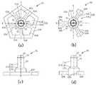
この弁体5Aは、図1(a)及び図1(b)に示されるように、円筒状の中実頭部21Aと、その大径部41の自由端側に輻状支持脚42aを介して配置された頭部支持部22Aと、輻状支持脚42aの先端に配置された環状の被保持部23Aとを有している。 As shown in FIGS. 1A and 1B, the valve body 5A has a cylindrical
中実頭部21Aは、小径部31と、その他端部に段差連続部47を介して連設された大径部41とを有している。小径部31、段差連続部47及び大径部41はいずれも中実体になっている。この小径部31は、コネクタ管4における第1の接続口11の内径及び大径部41の外径よりも小さな一定の外径を有し、その外周面は平坦で第1の接続口11の内周面16に非接触となる。大径部41は一定の外径を有し、段差連続部47は小径部31と大径部41とを接続する錐台形で小径部31の外径と同一の最小外径と、大径部41の外径と同一の最大外径を有している。小径部31は、その一端部、すなわち大径部41が連設された側と反対側の近傍に環状に突設された密接する環状シール部32と、小径部31の頂面に軸線方向に突設された突条33とを有している。環状シール部32は、後述するように、小径部31の周方向に一巡し、半円形の断面形状の鍔状に形成されており、第1の接続口11の内周面16に線接触状態で密接して、この接続口11を密閉する。突条33は、コネクタ管4における第1の接続口11からある程度突出するように、頂面の少なくとも一方向に連続又は不連続な突起として形成されている。具体的には、この突条33は、例えば図2(b)及び図2(c)によく示されるように、先端に向かって頂面全体から延びる先細となる錐形をしており、互いに対面する傾斜面で先細形状に構成されている。段差連続部47はその外周面で流路14に開口する第1の接続口11の開口部、すなわち第1の接続口11の流路14側開口に連設された環状逆テーパ面18を密閉する。したがって、段差連続部47の最大外径は開口部の開口径よりも大きく設定されている。大径部41は、頭部支持部22Aが連設され、小径部31及び段差連続部47を支持する。中実頭部21Aは、第1の接続口11の内周面16及びその開口部を密閉可能な寸法及び形状を有していればよく、前記した環状シール部32の外径及び段差連続部47の最大外径以外の外径及び軸線長さ等は収納されるコネクタ管4の形状及び寸法に応じて適宜に設定される。 The solid head 21 </ b> A has a small-
頭部支持部22Aは、図1(a)及び図1(b)に示されるように、2本の輻状支持脚42aと2つの空隙部43aとを有し、2本の輻状支持脚42aは大径部41の自由端から周方向に等間隔で軸線に対して略垂直方向に向かって互いに逆向きに放射状に延在する外径が中実頭部21A(突条33を除く。)の軸線長さに対して10〜30%の丸棒体に形成されている。2つの空隙部43aは中実頭部21Aの周方向に隣接する2つの輻状支持脚42aの間に配置され、大径部41の外周面から輻状支持脚42aの先端まで平面視略半円形に広がっている。このように、頭部支持部22Aは、後述する被保持部23Aと共に、2本の輻状支持脚42aがスポークとなった車輪を、構成している。このように構成された頭部支持部22A、すなわち2本の輻状支持脚42a及び2つの空隙部43aは、図1(a)に示されるように、弁体5Aの軸線Cを原点とする直交座標系(XY座標系)を想定したときに第1軸(X軸)及び第2軸(Y軸)それぞれに対して面対称になっている。なお、図1(a)には2本の輻状支持脚42aが第1軸(X軸)に沿うように直交座標系が図示されている。換言すると、2本の輻状支持脚42aの成す角度、すなわち空隙部43aの中心角それぞれが同一の180°になるように、2本の輻状支持脚42aが配置されている。したがって、頭部支持部22Aは、中実頭部21Aを軸線Cに対して実質的に傾倒又は傾斜することなく可逆移行させるように構成されている。このように配置された2つの輻状支持脚42a及び2つの空隙部43aは、頭部支持部22Aを軸線C方向から投影したときに2つの輻状支持脚42aと2つの空隙部43aとの全投影面積に対する2つの輻状支持脚42aの合計投影面積の面積割合が25〜50%の範囲になるように、例えば42%になるように、形状及び寸法が設定されている。 As shown in FIGS. 1A and 1B, the
ところで、膜状に形成された伸縮性エレメント20を備えた特許文献4の「針無しアクセス装置10」では可動ピストン18を付勢するために貫通孔を大きくできないのに対して、弁体5Aは、環状シール部32及び段差連続部47で第1の接続口11の内周面16及びその開口部を密閉すると共に前記面積割合を満たす丸棒体の輻状支持脚43aを有しているから、空隙部43aを大きくしても頭部支持部22Aは中実頭部21Aを支持し、高い密閉状態を保持できる。 By the way, in the “needleless access device 10” of Patent Document 4 provided with the stretchable element 20 formed in a film shape, the through hole cannot be enlarged because the
被保持部23Aは、図1(a)及び図1(b)に示されるように、2つの輻状支持脚42aそれぞれの先端に連設され、2つの輻状支持脚42aの先端それぞれを環状に連結する環状体に形成されている。したがって、この被保持部23Aは環状被保持部とも称される。被保持部23Aは、コネクタ管4の弁体収納部15、具体的にはキャップ4a及び本体5bで形成される環状凹部に狭圧保持される寸法を有していればよく、中実に形成されている。 As shown in FIG. 1A and FIG. 1B, the held
このように、弁体5Aは、中実頭部21Aと頭部支持部22Aと被保持部23Aとを備えているから、例えばコネクタ管4の弁体収納部15に収納されたときに、環状凹部で挟圧保持されて横架された頭部支持部で中実頭部が軸線に沿う起立状態に担持されて第1の接続口内に配置されるから、環状シール部32及び段差連続部47で第1の接続口11の内周面16を高いシール性で密閉できると共に、中実頭部21Aに作用する圧力のほとんどが均一に頭部支持部22Aに伝達され、中実頭部をほとんど傾倒等させることなく密閉状態から開放状態に容易に開放移行し、かつ開放状態から移行前の元の密閉状態に容易に復元移行する。 Thus, since the valve body 5A includes the
この発明に係るコネクタ用弁体の別の一例である弁体5Bは、図2(a)、図2(b)及び図2(c)に示されるように、頭部支持部が異なること以外は弁体5Aと基本的に同様である。すなわち、この弁体5Bは、中実頭部21Aと頭部支持部22Bと被保持部23Aと有している。弁体5Aと同様の構成についての説明は省略し、図2において同じ符号を付与する。 As shown in FIGS. 2 (a), 2 (b) and 2 (c), a
頭部支持部22Bは、輻状支持脚42b及び空隙部43bが異なること以外は頭部支持部22Aと基本的に同様である。すなわち、頭部支持部22Bは、周方向に等間隔に配置された3本の輻状支持脚42bと120°の中心角を有する平面視略扇形の3つの空隙部43bとを有し、被保持部23Aと共に車輪状に形成されている。そして、この頭部支持部22Bは、図2(a)に示されるように、前記直交座標系(XY座標系)の第1軸(X軸)及び第2軸(Y軸)それぞれに対して面対称になっている。このように配置された3本の輻状支持脚42b及び3つの空隙部43bは、頭部支持部22Bを軸線C方向から投影したときの前記面積割合が25〜50%の範囲になるように、例えば40%になるように、形状及び寸法が設定されている。 The
中実頭部21Aと頭部支持部22Bと被保持部23Aとを備えた弁体5Bは弁体5Aと基本的に同様の効果を奏し、特に3つの輻状支持脚42bを有する頭部支持部22Bはその対称性が高いから中実頭部21Aを軸線に沿って高精度に可逆移行させることができる。 The
この発明に係るコネクタ用弁体のまた別の一例である弁体5Cは、図3(a)及び図3(b)に示されるように、中実頭部、頭部支持部及び被保持部が異なること以外は弁体5Aと基本的に同様である。すなわち、この弁体5Cは、中実頭部21Bと頭部支持部22Cと被保持部23Bと有している。弁体5Aと同様の構成についての説明は省略し、図3(a)及び図3(b)において同じ符号を付与する。 As shown in FIGS. 3 (a) and 3 (b), a
中実頭部21Bは、図3(a)によく示されるように軸線に垂直な断面が正十二角形の角柱であること以外は中実頭部21Aと基本的に同様であり、被保持部23Bは平面視横長円形の環状に形成されていること以外は被保持部23Aと基本的に同様である。 The
頭部支持部22Cは、輻状支持脚42c及び空隙部43cが異なること以外は頭部支持部22Aと基本的に同様である。すなわち、頭部支持部22Cは、直交する2方向それぞれに互いに逆向きに放射状に延在する4本の第1輻状支持脚42c1及び前記2方向に45°で交差する方向に互いに逆向きに放射状に延在する2本の第2輻状支持脚42c2と、隣接する2本の第1輻状支持脚42c1の間に配置された第1空隙部43c1及び隣接する第1輻状支持脚42c1及び第2輻状支持脚42c2の間に配置された第2空隙部43c2とを有し、被保持部23Bと共に、横長円形の車輪状に形成されている。したがって、2本の第2輻状支持脚42c2は延在方向の長さが長くなっていること以外は第1輻状支持脚42c1と基本的に同様であり、第1空隙部43c1の中心角は90°で第2空隙部43c2の中心角は45°になっている。そして、この頭部支持部22Cは、図3(a)に示されるように、前記直交座標系(XY座標系)の第1軸(X軸)及び第2軸(Y軸)それぞれに対して面対称になっている。このように2本の第2輻状支持脚42c2に沿うように第1軸(X軸)を設定した場合には、頭部支持部22Cは、6本の輻状支持脚42cの先端それぞれに外接する外接楕円の長軸(前記第1軸に対応)及び短軸(前記第2軸に対応)に対して面対称になっているともいうことができる。なお、図3(a)には2本の第2輻状支持脚42c2が第1軸(X軸)に沿うように直交座標系が図示されているが、2本の第1輻状支持脚42c1が第1軸(X軸)に沿うように直交座標系が設定されてもよい。このように配置された6本の輻状支持脚42c1及び42c2並びに6つの空隙部43c1及び43c2は、頭部支持部22Cを軸線C方向から投影したときの前記面積割合が25〜50%の範囲になるように、例えば31%になるように、形状及び寸法が設定されている。 The
中実頭部21Bと頭部支持部22Cと被保持部23Bとを備えた弁体5Cは弁体5Aと基本的に同様の効果を奏し、特に頭部支持部22Cはその対称性が高いから中実頭部21Bを軸線に沿って高精度に可逆移行させることができる。 The
この発明に係るコネクタ用弁体のさらにまた別の一例である弁体5Dは、図3(c)及び図3(d)に示されるように、頭部支持部及び被保持部が異なること以外は弁体5Aと基本的に同様で、中実頭部及び被保持部が異なること以外は弁体5Cと基本的に同様である。すなわち、この弁体5Dは、中実頭部21Aと頭部支持部22Cと被保持部23Cと有している。弁体5A及び弁体5Cと同様の構成についての説明は省略し、図3(c)及び図3(d)において同じ符号を付与する。中実頭部21Aは弁体5Aの中実頭部21Aと、また頭部支持部22Cは弁体5Cの頭部支持部22Cと基本的に同様である。さらに被保持部23Cは平面視楕円形の環状に形成されていること以外は被保持部23A及び被保持部23Bと基本的に同様である。 As shown in FIGS. 3 (c) and 3 (d), a valve body 5D, which is still another example of the connector valve body according to the present invention, is different in that the head support portion and the held portion are different. Is basically the same as the valve body 5A, and is basically the same as the
中実頭部21Aと頭部支持部22Cと被保持部23Cとを備えた弁体5Dは弁体5Aと基本的に同様の効果を奏し、特に頭部支持部22Cはその対称性が高いから中実頭部21Aを軸線に沿って高精度に可逆移行させることができる。 The valve body 5D provided with the
この発明に係るコネクタ用弁体の一例である弁体5Eは、図4(a)及び図4(b)に示されるように、中実頭部、頭部支持部及び被保持部が異なること以外は弁体5Aと基本的に同様で、被保持部が異なること以外は弁体5Cと基本的に同様である。すなわち、この弁体5Eは、中実頭部21Bと頭部支持部22Cと被保持部23Dと有している。弁体5A及び弁体5Cと同様の構成についての説明は省略し、図4(a)及び図4(b)において同じ符号を付与する。中実頭部21Bは弁体5Cの中実頭部21Bと、また頭部支持部22Cは弁体5Cの頭部支持部22Cと基本的に同様である。さらに被保持部23Dは1組の第1被保持部44d1及び第1被保持部44d1よりも短い1組の第2被保持部44d2を有し、頭部支持部22Cと共に平面視長方形の車輪状に形成されていること以外は被保持部23Cと基本的に同様である。この被保持部23Dにおいて、4本の第1輻状支持脚42c1は被保持部23Dの隅部近傍の第1被保持部44d1に接続している。 As shown in FIGS. 4 (a) and 4 (b), the valve body 5E, which is an example of the connector valve body according to the present invention, has different solid heads, head support parts, and held parts. Is basically the same as the valve body 5A, and is basically the same as the
中実頭部21Bと頭部支持部22Cと被保持部23Dとを備えた弁体5Eは弁体5Aと基本的に同様の効果を奏し、特に頭部支持部22Cはその対称性が高いから中実頭部21Bを軸線に沿って高精度に可逆移行させることができる。 The valve body 5E provided with the
この発明に係るコネクタ用弁体の別の一例である弁体5Fは、図4(c)及び図4(d)に示されるように、実頭部、頭部支持部及び被保持部が異なること以外は弁体5Aと基本的に同様で、被保持部が異なること以外は弁体5Eと基本的に同様である。すなわち、この弁体5Fは、中実頭部21Bと頭部支持部22Cと被保持部23Eと有している。弁体5A及び弁体5Eと同様の構成についての説明は省略し、図4(c)及び図4(d)において同じ符号を付与する。中実頭部21Bは弁体5Eの中実頭部21Bと、また頭部支持部22Cは弁体5Eの頭部支持部22Cと基本的に同様である。さらに被保持部23Eはその隅部がR形状に整形されていること以外は弁体5Eの被保持部23Dと基本的に同様である。 As shown in FIGS. 4 (c) and 4 (d), a
中実頭部21Bと頭部支持部22Cと被保持部23Eとを備えた弁体5Fは弁体5Aと基本的に同様の効果を奏し、特に頭部支持部22Cはその対称性が高いから中実頭部21Bを軸線に沿って高精度に可逆移行させることができる。 The
この発明に係るコネクタ用弁体のまた別の一例である弁体5Gは、図5(a)及び図5(b)に示されるように、頭部支持部及び被保持部が異なること以外は弁体5Aと基本的に同様である。すなわち、この弁体5Gは、中実頭部21Aと頭部支持部22Dと被保持部23Fと有している。弁体5Aと同様の構成についての説明は省略し、図5(a)及び図5(b)において同じ符号を付与する。 As shown in FIGS. 5 (a) and 5 (b), a valve body 5G, which is another example of the connector valve body according to the present invention, except that the head support portion and the held portion are different. This is basically the same as the valve body 5A. That is, the valve body 5G has a
頭部支持部22Dは、輻状支持脚42d及び空隙部43dが異なること以外は頭部支持部22Aと基本的に同様である。すなわち、頭部支持部22Dは、周方向に等間隔に配置された5本の輻状支持脚42dと72°の中心角を有する平面視略菱形の5つの空隙部43dとを有し、被保持部23Fと共に平面視五角形の車輪状に形成されている。そして、この頭部支持部22Dは、図5(a)に示されるように、前記直交座標系(XY座標系)の第1軸(X軸)及び第2軸(Y軸)それぞれに対して面対称になっている。このように配置された5本の輻状支持脚43d及び5つの空隙部43dは、頭部支持部22Dを軸線C方向から投影したときの前記面積割合が25〜50%の範囲になるように、例えば25%になるように、形状及び寸法が設定されている。被保持部23Fは、輻状支持脚42dの延在方向に垂直な方向に延在して5本の輻状支持脚42dの先端それぞれを連結する平面視五角形に形成されている。 The head support 22D is basically the same as the
中実頭部21Aと頭部支持部22Dと被保持部23Fとを備えた弁体5Gは弁体5Aと基本的に同様の効果を奏し、特に頭部支持部22Dはその対称性が高いから中実頭部21Aを軸線に沿って高精度に可逆移行させることができる。 The valve body 5G provided with the
この発明に係るコネクタ用弁体のさらにまた別の一例である弁体5Hは、図5(c)及び図5(d)に示されるように、頭部支持部及び被保持部が異なること以外は弁体5Aと基本的に同様で、被保持部が異なること以外は弁体5Bと基本的に同様である。すなわち、この弁体5Hは、中実頭部21Aと頭部支持部22Bと被保持部23Gと有している。弁体5Aと同様の構成についての説明は省略し、図5(c)及び図5(d)において同じ符号を付与する。被保持部23Gは、輻状支持脚42bそれぞれの延在方向に垂直な方向に輻状支持脚42bの幅又は外径よりもわずかに長く延在し、両端部が輻状支持脚42bから突出するわずかに湾曲する円弧状に形成されている。すなわち、被保持部23Gそれぞれは輻状支持脚42bと共に平面視略T字形になっている。 As shown in FIGS. 5 (c) and 5 (d), the
中実頭部21Aと頭部支持部22Bと被保持部23Gとを備えた弁体5Gは弁体5Aと基本的に同様の効果を奏し、特に3つの輻状支持脚43bを有する頭部支持部22Bはその対称性が高いから中実頭部21Aを軸線に沿って高精度に可逆移行させることができる。 The valve body 5G provided with the
この発明に係る弁体は前記した例に限定されることはなくこの発明の目的を達成することができる範囲において、種々の変更が可能である。例えば、弁体5A、5B、5G及び5Hはいずれも輻状支持脚42a、42b及び42dが周方向に等間隔で配置されているが、この発明において、弁体は、中実頭部が自身の軸線に対して略平行な方向に可逆移行すれば、例えば弁体5C〜5Fのように、輻状支持脚が周方向に異なる間隔で配置されていてもよい。 The valve body according to the present invention is not limited to the above-described example, and various modifications can be made within a range in which the object of the present invention can be achieved. For example, all of the
弁体5A〜5Hにおいて、中実頭部21A及び21Bは共に段差連続部47を備えているが、この発明において、中実頭部は段差連続部を備えず、直接連設された小径部及び大径部を備えていればよい。この場合は、大径部の端面であって連設された小径部を囲繞する環状端面が段差部として機能し、第1の接続口11の開口を密閉する。 In the valve bodies 5A to 5H, the
弁体5A〜5Hにおいて、中実頭部21A及び21Bは共に1つの環状シール部32を有しているが、この発明において、中実頭部は複数の環状シール部を備えていてもよい。 In the valve bodies 5A to 5H, the
この発明において、弁体は、前記した各種の中実頭部、輻状支持脚及び被保持部を適宜に組み合わせて構成することができる。 In the present invention, the valve body can be configured by appropriately combining the various solid heads, the radial support legs, and the held parts.
この発明に係るコネクタは、少なくとも2つの管体同士を接続するコネクタ、例えば、前記医療用コネクタ、特に、前記チューブと針無し管体とを接続する医療用コネクタすなわち混注管等として好適に用いられる。そして、この発明に係るコネクタは、コネクタ管とこの発明に係るコネクタ用弁体とを備えており、この発明に係るコネクタ用弁体は、前記したように、中実頭部及び頭部支持部を備え、中実頭部で第1の接続口を密閉する密閉状態と、コネクタ用弁体の軸線方向に作用する圧力で頭部支持部が伸張して第1の接続口の密閉状態が解除される開放状態とに移行可能になっている。この発明に係るコネクタ用弁体が密閉状態にあるとその中実頭部の環状シール部及び段差部の外周面が第1の接続口の内面及び開口部に密接してこの接続口を液密にシールする。一方、頭部支持部が伸張すると中実頭部がコネクタ管4内まで後退しているから解放状態になり、管体の内腔とコネクタ管の流路とが弁体収納部又は第1の接続口内で連通して管体の内腔からコネクタ管内に流体が供給される。流体の供給が終了した後に管体を第1の接続口から抜脱すなわち退避させると、この発明に係るコネクタ用弁体にかかっていた押圧力が解除されて頭部支持部の反発力又は復元力で中実頭部が軸線に沿って元の状態に復帰して、すなわち復元移行して、第1の接続口を液密にシールする。このようにしてこの発明に係るコネクタはシール性の高い密閉状態から開放状態に容易に移行し、かつ元の密閉状態に復元移行する。 The connector according to the present invention is suitably used as a connector for connecting at least two pipes, for example, the medical connector, particularly a medical connector for connecting the tube and a needleless pipe, that is, a mixed injection pipe or the like. . The connector according to the present invention includes a connector pipe and the connector valve body according to the present invention. As described above, the connector valve body according to the present invention includes a solid head and a head support portion. And the sealed state in which the first connection port is sealed with the solid head and the head support part is extended by the pressure acting in the axial direction of the connector valve body, and the sealed state of the first connection port is released. It is possible to shift to the open state. When the connector valve body according to the present invention is in a hermetically sealed state, the annular seal portion of the solid head and the outer peripheral surface of the stepped portion are in close contact with the inner surface and the opening of the first connection port, and the connection port is liquid-tight. To seal. On the other hand, when the head support portion is extended, the solid head is retracted into the connector tube 4 and thus is released, and the lumen of the tube body and the flow path of the connector tube are connected to the valve body housing portion or the first body. A fluid is supplied into the connector tube from the lumen of the tube through communication in the connection port. When the pipe body is pulled out or retracted from the first connection port after the supply of the fluid is completed, the pressing force applied to the connector valve body according to the present invention is released, and the repulsive force or restoration of the head support portion With the force, the solid head returns to the original state along the axis, that is, restores and moves, and the first connection port is liquid-tightly sealed. In this way, the connector according to the present invention easily shifts from a sealed state having a high sealing property to an open state, and reverts to the original sealed state.
この発明に係るコネクタの一例であるコネクタ1は、図6(a)に示されるように、針無し管体81を接続可能な第1の接続口11、患者に留置されたカテーテル等に連結された、図示しない管体が接続される第2の接続口12、及び、患者に投与する流体を収納したバッグ等に連結された、図示しない管体が接続される第3の接続口13、これらの接続口11〜13を連通させる流路14、並びに、流路14における第1の接続口11の近傍の内周面に凹設配置された弁体保持部15を有するコネクタ管4と、コネクタ管4の弁体収納部15に内蔵されるコネクタ用弁体5Aとを備えている。 A connector 1 which is an example of a connector according to the present invention is connected to a
このようなコネクタ管4は弁体5Aを内蔵できる限り従来公知のコネクタ管を限定されることなく用いることができ、例えば、図6に示されるように、第2の接続口12及び第3の接続口13を有する一端が開口する本体4bと、第1の接続口11及びこの接続口11の開口部、具体的にはその開口から連接され、内径が徐々に拡大する環状逆テーパ面18を有し、本体4bの開口に配置されるキャップ4aとからなる平面視略T字状のコネクタ管4、平面視略Y字状のコネクタ管、平面視略十字状のコネクタ管等が挙げられる。コネクタ管4は、その軸線方向の一端側に針無し管体81が接続される第1の接続口11が配置され、他端側にカテーテル等に連結された管体が接続される第2の接続口12が配置され、前記軸線方向に交差する方向に突出し、流体を収納したバッグ等に連結された管体が接続される第3の接続口13が配置されている。そして、キャップ4aと本体4bとの接続部に弁体5Aの被保持部23Aを挟圧保持して収納する環状凹部としての弁体収納部15が画成されている。コネクタ管4の各接続口11〜13には必要に応じて、後述する針無し管体と接続可能な構造又は接続を一時的に保持可能な構造、例えば、ルアーロックネジ等が形成されている。このキャップ4aと本体4bとは超音波溶着又は接着等により液密に形成されている。 As long as the connector body 4 can incorporate the valve body 5A, a conventionally known connector pipe can be used without limitation. For example, as shown in FIG. 6, the
コネクタ1に接続される針無し管体81は、内腔81aすなわち流体を流通させる流路を内部に有していれば特に限定されず、前記した各種の管体が挙げられる。図6(a)に示されるように、この管体の先端部82は第1の接続口11に接続可能な形状になっており、通常、第1の接続口11の内径よりも僅かに小さな外径を有する小径環状構造になっている。この先端部82の外周面には第1の接続口11に所望により形成されたルアーロックに螺合するルアー溝を有していてもよい。 The
コネクタ管4及び針無し管体81は通常剛性のある材料、例えば、各種樹脂、各種ガラス、各種セラミックス、各種金属で形成される。樹脂としては、例えば、ポリエチレン、ポリプロピレン、エチレン−プロピレン共重合体、エチレン−酢酸ビニル共重合体(EVA)等のポリオレフィン、ポリ塩化ビニル、ポリ塩化ビニリデン、ポリスチレン、ポリアミド、ポリイミド、ポリアミドイミド、ポリカーボネート、ポリ−(4−メチルペンテン−1)、アイオノマー、アクリル系樹脂、ポリメチルメタクリレート、アクリロニトリル−ブタジエン−スチレン共重合体(ABS樹脂)、アクリロニトリル−スチレン共重合体(AS樹脂)、ブタジエン−スチレン共重合体、ポリエチレンテレフタレート(PET)、ポリブチレンテレフタレート(PBT)、ポリシクロヘキサンテレフタレート(PCT)等のポリエステル、ポリエーテル、ポリエーテルケトン(PEK)、ポリエーテルエーテルケトン(PEEK)、ポリエーテルイミド、ポリアセタール(POM)、ポリフェニレンオキシド、変性ポリフェニレンオキシド、ポリサルフォン、ポリエーテルサルフォン、ポリフェニレンサルファイド、ポリアリレート、芳香族ポリエステル(液晶ポリマー)、ポリテトラフルオロエチレン、ポリフッ化ビニリデン、フッ素系樹脂、又はこれら樹脂を1種以上含むブレンド体、ポリマーアロイ等が挙げられる。 The connector tube 4 and the
コネクタ1は、図6(a)に示されるように、針無し管体81が第1の接続口11に接続されていないとき、すなわち密閉状態にあるときは、弁体収納部15に収納された弁体5Aは、弁体保持部15に挟圧保持され横架された頭部支持部22Aで起立状態に担持された中実頭部21Aの少なくとも一部、この例では小径部31が第1の接続口11の内部に配置されるように、中実頭部21Aが軸線C方向にほぼ直立した姿勢をとっている。このとき、中実頭部21Aの環状シール部32が第1の接続口11の内周面16に密接すると共に、中実頭部21Aの段差連続部47の外周面又は段差連続部47の最大外径部が第1の接続口11の開口部すなわち環状逆テーパ面18に密閉する。このようにして第1の接続口11が高いシール性で密閉されている。この姿勢において、中実頭部21Aの突条33は第1の接続口11から突出しているから容易に清掃することができ、衛生面に優れる。また、弁体収納部15に収納された弁体5Aは、その中実頭部21Aの外周に弁体収納部15の内面と共に流体を流通させる環状の流通路を形成し、かつその空隙部43aを軸線C方向に沿って第2の接続口12に向けて流体を流通させる流路として機能させる。 As shown in FIG. 6A, the connector 1 is stored in the valve
コネクタ1を介して患者に流体を供給するには、図6(b)に示されるように、管体81の先端部82を弁体5Aの弾発力、具体的には頭部支持部22Aの弾発力に反して第1の接続口11に圧入する。そうすると、弁体5Aは第1の接続口11に接続された針無し管体81による弁体5Aの軸線C方向に作用した押圧力のほとんどすべてが横架された頭部支持部22Aに伝達されて頭部支持部22Aが全体として軸線C方向に伸張し、それに伴って第1の接続口11を密閉していた中実頭部21Aが軸線C方向に沿って後退して弁体収納部15内に埋没する。一方、軸線Cに沿って第1の接続口11に圧入された針無し管体81の先端面と中実頭部21Aの突条33との間に存在する空間83を経て針無し管体81からコネクタ管4に注入される。このように管体81の先端部82を第1の接続口11に圧入すると針無し管体81の内腔81aと流路14とが連通した、コネクタ1すなわち第1の接続口11が開放された開放状態になる。そして、注入された流体は弁体5Aの外周に形成された環状の流通路並びに空隙部43aを流通して第2の接続口12に流入する。 In order to supply a fluid to the patient via the connector 1, as shown in FIG. 6B, the
このようにして所望の流体を注入した後に針無し管体81を第1の接続口11から抜脱すると、針無し管体81により負荷された押圧力が解除されて反発力又は復元力で頭部支持部22Aが横架状態に復帰するのに伴って中実頭部21Aが軸線Cに沿って前進し、元の密閉状態に復帰する。このようにして弁体5Aが元の密閉状態に密閉移行して第1の接続口11が再度高いシール性で密閉される。このように弁体5Aを備えたコネクタ1は、中実頭部21Aが軸線C方向に高精度に沿って前後進して、密閉状態から開放状態に容易に移行すると共に移行した開放状態から移行前の元の密閉状態に容易に復元移行する。 When the needleless
なお、弁体5Aを備えたコネクタ1についてその構造及び作用を説明したが、弁体5Aに代えて弁体5B〜5Hのいずれを備えたコネクタであっても同様に機能する。 In addition, although the structure and effect | action were demonstrated about the connector 1 provided with 5 A of valve bodies, it replaces with the valve body 5A, and it functions similarly even if it is provided with any of the
この発明に係るコネクタは前記した例に限定されることはなく、この発明の目的を達成することができる範囲において、種々の変更が可能である。 The connector according to the present invention is not limited to the above-described example, and various modifications can be made as long as the object of the present invention can be achieved.
1 コネクタ
4 コネクタ管
4a キャップ
4b 本体
5A〜5H コネクタ用弁体(弁体)
11 第1の接続口
12 第2の接続口
13 第3の接続口
14 流路
15 弁体保持部
16 内周面
18 環状逆テーパ面
21A、21B 中実頭部
22A〜22D 頭部支持部
23A〜23G 被保持部
31 小径部
32 環状シール部
33 突条
34 外周面
41 大径部
42a、42b、42d 輻状支持脚
42c1 第1輻状支持脚
42c2 第2輻状支持脚
43a、43b、43d 空隙部
43c1 第1空隙部
43c2 第2空隙部
44d1 第1被保持部
44d2 第2被保持部
47 段差連続部(段差部)
81 針無し管体
81a 内腔
82 先端部
83 空間1 Connector 4
DESCRIPTION OF
81
前記課題を解決するための手段であるこの発明に係るコネクタ用弁体は、管体を接続可能な少なくとも2つの接続口、これらの接続口を連通する流路、及び、第1の前記接続口の近傍に配置された弁体保持部を有するコネクタ管に収納され、流体の流通を制御するコネクタ用弁体であって、
一端部近傍に環状に突設され、前記第1の接続口の内周面に密接する環状シール部及び頂面に突設された突条を有する小径部、並びに、前記小径部の他端部に連設された大径部を有する中実頭部と、
前記大径部の自由端から周方向に間隔をあけて略水平方向に放射状に延在する複数の輻状支持脚、及び、周方向に隣接する前記輻状支持脚の間に配置され、前記大径部の外周面から前記輻状支持脚の先端まで広がる複数の空隙部を有する頭部支持部とを備え、前記頭部支持部を軸線方向から投影したときに前記輻状支持脚と前記空隙部との全投影面積に対する前記輻状支持脚の合計投影面積の面積割合が25〜50%であり、前記輻状支持脚が前記中実頭部(突条を除く。)の軸線長さに対して10〜30%の幅又は外径を有していることを特徴とする。
The connector valve body according to the present invention, which is means for solving the above-described problems, includes at least two connection ports to which a tube body can be connected, a flow path communicating these connection ports, and the first connection port. A valve body for a connector, which is housed in a connector pipe having a valve body holding portion disposed in the vicinity of and controls the flow of fluid,
A small-diameter portion projecting annularly in the vicinity of one end and having a ring-shaped seal portion in close contact with the inner peripheral surface of the first connection port and a protrusion projecting from the top surface, and the other end of the small-diameter portion A solid head having a large-diameter portion connected to
A plurality of radial support legs extending radially in a substantially horizontal direction with a circumferential interval from a free end of the large diameter portion, and disposed between the radial support legs adjacent in the circumferential direction, A head support portion having a plurality of gaps extending from the outer peripheral surface of the large-diameter portion to the tip of theradial support leg, and when the head support portion is projected from the axial direction, the radial support leg and the The area ratio of the total projected area of the radial support leg to the total projected area with the gap is 25 to 50%, and the radial support leg is the axial length of the solid head (excluding protrusions). It has a width or outer diameter of 10 to 30% with respect to the above.
前記課題を解決するための手段であるこの発明に係るコネクタ用弁体は、管体を接続可能な少なくとも2つの接続口、これらの接続口を連通する流路、及び、第1の前記接続口の近傍に配置された弁体保持部を有するコネクタ管に収納され、流体の流通を制御するコネクタ用弁体であって、
一端部近傍に環状に突設され、前記第1の接続口の内周面に密接する環状シール部及び頂面に突設された突条を有する小径部、並びに、前記小径部の他端部に連設された大径部を有する中実頭部と、
前記大径部の自由端から周方向に間隔をあけて略水平方向に放射状に延在する複数の輻状支持脚、及び、周方向に隣接する前記輻状支持脚の間に配置され、前記大径部の外周面から前記輻状支持脚の先端まで広がる複数の空隙部を有する頭部支持部とを備え、
前記頭部支持部は前記コネクタ管を密閉する密閉面を有さず、
前記頭部支持部を軸線方向から投影したときに前記輻状支持脚と前記空隙部との全投影面積に対する前記輻状支持脚の合計投影面積の面積割合が25〜50%であり、前記輻状支持脚が前記中実頭部(突条を除く。)の軸線長さに対して10〜30%の幅又は外径を有していることを特徴とする。
The connector valve body according to the present invention, which is means for solving the above-described problems, includes at least two connection ports to which a tube body can be connected, a flow path communicating these connection ports, and the first connection port. A valve body for a connector, which is housed in a connector pipe having a valve body holding portion disposed in the vicinity of and controls the flow of fluid,
A small-diameter portion projecting annularly in the vicinity of one end and having a ring-shaped seal portion in close contact with the inner peripheral surface of the first connection port and a protrusion projecting from the top surface, and the other end of the small-diameter portion A solid head having a large-diameter portion connected to
A plurality of radial support legs extending radially in a substantially horizontal direction with a circumferential interval from a free end of the large diameter portion, and disposed between the radial support legs adjacent in the circumferential direction, A head support portion having a plurality of gaps extending from the outer peripheral surface of the large diameter portion to the tip of the radial support leg,
The head support portion does not have a sealing surface that seals the connector tube,
The area ratio of the total projected area of the radial support legs to the total projected area of the radial support legs and the gap when the head support part is projected from the axial direction is 25 to 50%, and the radiation The shaped support legs have a width or an outer diameter of 10 to 30% with respect to the axial length of the solid head (excluding the protrusion).
Claims (8)
Translated fromJapanese一端部近傍に環状に突設され、前記第1の接続口の内周面に密接する環状シール部及び頂面に突設された突条を有する小径部、並びに、前記小径部の他端部に連設された大径部を有する中実頭部と、
前記大径部の自由端から周方向に間隔をあけて略水平方向に放射状に延在する複数の輻状支持脚、及び、周方向に隣接する前記輻状支持脚の間に配置され、前記大径部の外周面から前記輻状支持脚の先端まで広がる複数の空隙部を有する頭部支持部とを備えていることを特徴とするコネクタ用弁体。At least two connection ports connectable to the tube body, a flow path communicating these connection ports, and a connector tube having a valve body holding portion disposed in the vicinity of the first connection port; A valve body for a connector for controlling distribution,
A small-diameter portion projecting annularly in the vicinity of one end and having a ring-shaped seal portion in close contact with the inner peripheral surface of the first connection port and a protrusion projecting from the top surface, and the other end of the small-diameter portion A solid head having a large-diameter portion connected to
A plurality of radial support legs extending radially in a substantially horizontal direction with a circumferential interval from a free end of the large diameter portion, and disposed between the radial support legs adjacent in the circumferential direction, A connector valve body, comprising: a head support portion having a plurality of gaps extending from the outer peripheral surface of the large diameter portion to the tip of the radial support leg.
前記弁体保持部に収納され、前記小径部の少なくとも一部が前記第1の前記接続口内に配置された請求項1〜5のいずれか1項に記載のコネクタ用弁体とを備えていることを特徴とするコネクタ。A connector pipe having at least two connection ports to which the tube body can be connected, a flow path communicating these connection ports, and a valve body holding portion disposed in the vicinity of the first connection port;
The connector valve body according to any one of claims 1 to 5, wherein the connector valve body is housed in the valve body holding portion, and at least a part of the small diameter portion is disposed in the first connection port. A connector characterized by that.
Priority Applications (1)
| Application Number | Priority Date | Filing Date | Title |
|---|---|---|---|
| JP2012112651AJP5311598B1 (en) | 2012-05-16 | 2012-05-16 | Connector valve body and connector |
Applications Claiming Priority (1)
| Application Number | Priority Date | Filing Date | Title |
|---|---|---|---|
| JP2012112651AJP5311598B1 (en) | 2012-05-16 | 2012-05-16 | Connector valve body and connector |
Publications (2)
| Publication Number | Publication Date |
|---|---|
| JP5311598B1 JP5311598B1 (en) | 2013-10-09 |
| JP2013236811Atrue JP2013236811A (en) | 2013-11-28 |
Family
ID=49529561
Family Applications (1)
| Application Number | Title | Priority Date | Filing Date |
|---|---|---|---|
| JP2012112651AActiveJP5311598B1 (en) | 2012-05-16 | 2012-05-16 | Connector valve body and connector |
Country Status (1)
| Country | Link |
|---|---|
| JP (1) | JP5311598B1 (en) |
Cited By (1)
| Publication number | Priority date | Publication date | Assignee | Title |
|---|---|---|---|---|
| KR101698353B1 (en)* | 2015-10-29 | 2017-01-23 | 한국생산기술연구원 | Cartridge Unit and Drug Infusion Device Having the Same |
Citations (7)
| Publication number | Priority date | Publication date | Assignee | Title |
|---|---|---|---|---|
| US5360413A (en)* | 1991-12-06 | 1994-11-01 | Filtertek, Inc. | Needleless access device |
| JPH07190207A (en)* | 1993-11-19 | 1995-07-28 | Novoste Corp | Fluid access and flow control valve |
| US5509433A (en)* | 1993-10-13 | 1996-04-23 | Paradis; Joseph R. | Control of fluid flow |
| JP2003180830A (en)* | 2001-12-17 | 2003-07-02 | Retug Inc | Automatic instillation stoppage apparatus |
| US20050178462A1 (en)* | 2003-04-28 | 2005-08-18 | Daniel Py | Container with valve assembly for filling and dispensing substances, and apparatus and method for filling |
| JP4432339B2 (en)* | 2003-03-17 | 2010-03-17 | ニプロ株式会社 | Medical valve |
| JP2013022420A (en)* | 2011-07-26 | 2013-02-04 | Shin Etsu Polymer Co Ltd | Valve body for connector, and connector |
- 2012
- 2012-05-16JPJP2012112651Apatent/JP5311598B1/enactiveActive
Patent Citations (8)
| Publication number | Priority date | Publication date | Assignee | Title |
|---|---|---|---|---|
| US5360413A (en)* | 1991-12-06 | 1994-11-01 | Filtertek, Inc. | Needleless access device |
| US5509433A (en)* | 1993-10-13 | 1996-04-23 | Paradis; Joseph R. | Control of fluid flow |
| JPH07190207A (en)* | 1993-11-19 | 1995-07-28 | Novoste Corp | Fluid access and flow control valve |
| US5462255A (en)* | 1993-11-19 | 1995-10-31 | Novoste Corporation | Automatic fluid control valve |
| JP2003180830A (en)* | 2001-12-17 | 2003-07-02 | Retug Inc | Automatic instillation stoppage apparatus |
| JP4432339B2 (en)* | 2003-03-17 | 2010-03-17 | ニプロ株式会社 | Medical valve |
| US20050178462A1 (en)* | 2003-04-28 | 2005-08-18 | Daniel Py | Container with valve assembly for filling and dispensing substances, and apparatus and method for filling |
| JP2013022420A (en)* | 2011-07-26 | 2013-02-04 | Shin Etsu Polymer Co Ltd | Valve body for connector, and connector |
Cited By (1)
| Publication number | Priority date | Publication date | Assignee | Title |
|---|---|---|---|---|
| KR101698353B1 (en)* | 2015-10-29 | 2017-01-23 | 한국생산기술연구원 | Cartridge Unit and Drug Infusion Device Having the Same |
Also Published As
| Publication number | Publication date |
|---|---|
| JP5311598B1 (en) | 2013-10-09 |
Similar Documents
| Publication | Publication Date | Title |
|---|---|---|
| CN109715246B (en) | Male connector, medical instrument, and connection method | |
| JP5265680B2 (en) | Connector and infusion tube set | |
| JP7258202B2 (en) | Closed system stress resistant membrane | |
| ES2671333T3 (en) | Rinse syringe positive displacement | |
| CN116528937A (en) | Male connector and medical instrument | |
| JPWO2006068211A1 (en) | Connectors, tube assemblies, infusion tube sets and medical containers | |
| CN108367145A (en) | Female connector | |
| JP2013022415A (en) | Valving element for connector and connector | |
| JP6709777B2 (en) | Male connector and infusion set | |
| JP5311598B1 (en) | Connector valve body and connector | |
| JPWO2018174265A1 (en) | Medical connector | |
| JP5327987B2 (en) | Connector valve body and connector | |
| JP5241045B2 (en) | Connector valve body and connector | |
| JP7298595B2 (en) | female connector | |
| JP4156790B2 (en) | Prefilled syringe and prefilled syringe | |
| JP2015066205A (en) | Medical connector, mixed injection tube, three-way stopcock, and medicament bag | |
| JP2011072395A (en) | Implement for mixing and injecting medicine into medical container | |
| JP2014050524A (en) | Connector valve element and connector | |
| JP2014050525A (en) | Connector valve element and connector | |
| JP2013022419A (en) | Valve body for connector, and connector | |
| JP2004298618A (en) | Medical valve | |
| US12357808B1 (en) | Connector assembly for communication of medical liquids | |
| JP2013068250A (en) | Connector | |
| JP2006212084A (en) | Connector | |
| JP2013022416A (en) | Valving element for connector and connector |
Legal Events
| Date | Code | Title | Description |
|---|---|---|---|
| A02 | Decision of refusal | Free format text:JAPANESE INTERMEDIATE CODE: A02 Effective date:20130118 | |
| TRDD | Decision of grant or rejection written | ||
| A01 | Written decision to grant a patent or to grant a registration (utility model) | Free format text:JAPANESE INTERMEDIATE CODE: A01 Effective date:20130628 | |
| A61 | First payment of annual fees (during grant procedure) | Free format text:JAPANESE INTERMEDIATE CODE: A61 Effective date:20130628 | |
| R150 | Certificate of patent or registration of utility model | Ref document number:5311598 Country of ref document:JP Free format text:JAPANESE INTERMEDIATE CODE: R150 Free format text:JAPANESE INTERMEDIATE CODE: R150 | |
| R250 | Receipt of annual fees | Free format text:JAPANESE INTERMEDIATE CODE: R250 | |
| R250 | Receipt of annual fees | Free format text:JAPANESE INTERMEDIATE CODE: R250 | |
| R250 | Receipt of annual fees | Free format text:JAPANESE INTERMEDIATE CODE: R250 | |
| S531 | Written request for registration of change of domicile | Free format text:JAPANESE INTERMEDIATE CODE: R313531 | |
| R350 | Written notification of registration of transfer | Free format text:JAPANESE INTERMEDIATE CODE: R350 | |
| R250 | Receipt of annual fees | Free format text:JAPANESE INTERMEDIATE CODE: R250 |