JP2013235855A - Lighting device - Google Patents
Lighting deviceDownload PDFInfo
- Publication number
- JP2013235855A JP2013235855AJP2013158024AJP2013158024AJP2013235855AJP 2013235855 AJP2013235855 AJP 2013235855AJP 2013158024 AJP2013158024 AJP 2013158024AJP 2013158024 AJP2013158024 AJP 2013158024AJP 2013235855 AJP2013235855 AJP 2013235855A
- Authority
- JP
- Japan
- Prior art keywords
- light
- lighting device
- illuminating body
- light emitting
- extraction layer
- Prior art date
- Legal status (The legal status is an assumption and is not a legal conclusion. Google has not performed a legal analysis and makes no representation as to the accuracy of the status listed.)
- Granted
Links
- 238000000605extractionMethods0.000claimsabstractdescription58
- 239000000463materialSubstances0.000claimsabstractdescription46
- 239000010410layerSubstances0.000claimsdescription70
- 238000005286illuminationMethods0.000claimsdescription38
- 230000003287optical effectEffects0.000claimsdescription35
- 229920000642polymerPolymers0.000claimsdescription7
- 239000011241protective layerSubstances0.000claimsdescription6
- 239000004973liquid crystal related substanceSubstances0.000claimsdescription4
- -1polyethylenePolymers0.000claimsdescription4
- 229920003229poly(methyl methacrylate)Polymers0.000claimsdescription3
- 239000004926polymethyl methacrylateSubstances0.000claimsdescription3
- 239000004952PolyamideSubstances0.000claimsdescription2
- 239000004698PolyethyleneSubstances0.000claimsdescription2
- 239000004743PolypropyleneSubstances0.000claimsdescription2
- 239000004793PolystyreneSubstances0.000claimsdescription2
- 229910004298SiO 2Inorganic materials0.000claimsdescription2
- 229920002647polyamidePolymers0.000claimsdescription2
- 239000004417polycarbonateSubstances0.000claimsdescription2
- 229920000515polycarbonatePolymers0.000claimsdescription2
- 229920000573polyethylenePolymers0.000claimsdescription2
- 229920001155polypropylenePolymers0.000claimsdescription2
- 229920002223polystyrenePolymers0.000claimsdescription2
- 230000001678irradiating effectEffects0.000abstract6
- 230000004907fluxEffects0.000description6
- 239000011368organic materialSubstances0.000description6
- 230000001902propagating effectEffects0.000description4
- 230000000694effectsEffects0.000description3
- 239000000758substrateSubstances0.000description3
- 239000010409thin filmSubstances0.000description3
- OAICVXFJPJFONN-UHFFFAOYSA-NPhosphorusChemical compound[P]OAICVXFJPJFONN-UHFFFAOYSA-N0.000description2
- 238000010521absorption reactionMethods0.000description2
- 229910052782aluminiumInorganic materials0.000description2
- XAGFODPZIPBFFR-UHFFFAOYSA-NaluminiumChemical compound[Al]XAGFODPZIPBFFR-UHFFFAOYSA-N0.000description2
- 230000002238attenuated effectEffects0.000description2
- 238000006243chemical reactionMethods0.000description2
- 230000001419dependent effectEffects0.000description2
- 230000005611electricityEffects0.000description2
- 238000000034methodMethods0.000description2
- 239000000203mixtureSubstances0.000description2
- 239000004065semiconductorSubstances0.000description2
- 230000003595spectral effectEffects0.000description2
- RYGMFSIKBFXOCR-UHFFFAOYSA-NCopperChemical compound[Cu]RYGMFSIKBFXOCR-UHFFFAOYSA-N0.000description1
- 229910004283SiO 4Inorganic materials0.000description1
- 239000000853adhesiveSubstances0.000description1
- 230000001070adhesive effectEffects0.000description1
- 230000003321amplificationEffects0.000description1
- 238000000149argon plasma sinteringMethods0.000description1
- 230000001427coherent effectEffects0.000description1
- 229910052802copperInorganic materials0.000description1
- 239000010949copperSubstances0.000description1
- 238000010586diagramMethods0.000description1
- 239000011521glassSubstances0.000description1
- 230000007062hydrolysisEffects0.000description1
- 238000006460hydrolysis reactionMethods0.000description1
- AMGQUBHHOARCQH-UHFFFAOYSA-Nindium;oxotinChemical compound[In].[Sn]=OAMGQUBHHOARCQH-UHFFFAOYSA-N0.000description1
- 229910010272inorganic materialInorganic materials0.000description1
- 239000011147inorganic materialSubstances0.000description1
- 230000003993interactionEffects0.000description1
- NJPPVKZQTLUDBO-UHFFFAOYSA-NnovaluronChemical compoundC1=C(Cl)C(OC(F)(F)C(OC(F)(F)F)F)=CC=C1NC(=O)NC(=O)C1=C(F)C=CC=C1FNJPPVKZQTLUDBO-UHFFFAOYSA-N0.000description1
- 238000003199nucleic acid amplification methodMethods0.000description1
- 239000002245particleSubstances0.000description1
- 230000002093peripheral effectEffects0.000description1
- 238000003825pressingMethods0.000description1
- 230000005855radiationEffects0.000description1
- 230000002441reversible effectEffects0.000description1
- 230000000630rising effectEffects0.000description1
- 238000006748scratchingMethods0.000description1
- 230000002393scratching effectEffects0.000description1
- 238000007493shaping processMethods0.000description1
- 238000001228spectrumMethods0.000description1
- 230000004936stimulating effectEffects0.000description1
- 238000001429visible spectrumMethods0.000description1
Images


Classifications
- F—MECHANICAL ENGINEERING; LIGHTING; HEATING; WEAPONS; BLASTING
- F21—LIGHTING
- F21S—NON-PORTABLE LIGHTING DEVICES; SYSTEMS THEREOF; VEHICLE LIGHTING DEVICES SPECIALLY ADAPTED FOR VEHICLE EXTERIORS
- F21S9/00—Lighting devices with a built-in power supply; Systems employing lighting devices with a built-in power supply
- F21S9/02—Lighting devices with a built-in power supply; Systems employing lighting devices with a built-in power supply the power supply being a battery or accumulator
- F21S9/03—Lighting devices with a built-in power supply; Systems employing lighting devices with a built-in power supply the power supply being a battery or accumulator rechargeable by exposure to light
- F21S9/037—Lighting devices with a built-in power supply; Systems employing lighting devices with a built-in power supply the power supply being a battery or accumulator rechargeable by exposure to light the solar unit and the lighting unit being located within or on the same housing
- F—MECHANICAL ENGINEERING; LIGHTING; HEATING; WEAPONS; BLASTING
- F21—LIGHTING
- F21S—NON-PORTABLE LIGHTING DEVICES; SYSTEMS THEREOF; VEHICLE LIGHTING DEVICES SPECIALLY ADAPTED FOR VEHICLE EXTERIORS
- F21S6/00—Lighting devices intended to be free-standing
- F21S6/002—Table lamps, e.g. for ambient lighting
- F21S6/003—Table lamps, e.g. for ambient lighting for task lighting, e.g. for reading or desk work, e.g. angle poise lamps
- F—MECHANICAL ENGINEERING; LIGHTING; HEATING; WEAPONS; BLASTING
- F21—LIGHTING
- F21V—FUNCTIONAL FEATURES OR DETAILS OF LIGHTING DEVICES OR SYSTEMS THEREOF; STRUCTURAL COMBINATIONS OF LIGHTING DEVICES WITH OTHER ARTICLES, NOT OTHERWISE PROVIDED FOR
- F21V23/00—Arrangement of electric circuit elements in or on lighting devices
- F21V23/04—Arrangement of electric circuit elements in or on lighting devices the elements being switches
- F—MECHANICAL ENGINEERING; LIGHTING; HEATING; WEAPONS; BLASTING
- F21—LIGHTING
- F21V—FUNCTIONAL FEATURES OR DETAILS OF LIGHTING DEVICES OR SYSTEMS THEREOF; STRUCTURAL COMBINATIONS OF LIGHTING DEVICES WITH OTHER ARTICLES, NOT OTHERWISE PROVIDED FOR
- F21V33/00—Structural combinations of lighting devices with other articles, not otherwise provided for
- F21V33/0004—Personal or domestic articles
- F21V33/0048—Office articles, e.g. bookmarks, desk lamps with drawers, stands for books or music scores
- G—PHYSICS
- G02—OPTICS
- G02B—OPTICAL ELEMENTS, SYSTEMS OR APPARATUS
- G02B6/00—Light guides; Structural details of arrangements comprising light guides and other optical elements, e.g. couplings
- G02B6/0001—Light guides; Structural details of arrangements comprising light guides and other optical elements, e.g. couplings specially adapted for lighting devices or systems
- G02B6/0003—Light guides; Structural details of arrangements comprising light guides and other optical elements, e.g. couplings specially adapted for lighting devices or systems the light guides being doped with fluorescent agents
- G—PHYSICS
- G02—OPTICS
- G02B—OPTICAL ELEMENTS, SYSTEMS OR APPARATUS
- G02B6/00—Light guides; Structural details of arrangements comprising light guides and other optical elements, e.g. couplings
- G02B6/0001—Light guides; Structural details of arrangements comprising light guides and other optical elements, e.g. couplings specially adapted for lighting devices or systems
- G02B6/0011—Light guides; Structural details of arrangements comprising light guides and other optical elements, e.g. couplings specially adapted for lighting devices or systems the light guides being planar or of plate-like form
- G02B6/0033—Means for improving the coupling-out of light from the light guide
- G02B6/0035—Means for improving the coupling-out of light from the light guide provided on the surface of the light guide or in the bulk of it
- G02B6/0038—Linear indentations or grooves, e.g. arc-shaped grooves or meandering grooves, extending over the full length or width of the light guide
- G—PHYSICS
- G02—OPTICS
- G02B—OPTICAL ELEMENTS, SYSTEMS OR APPARATUS
- G02B6/00—Light guides; Structural details of arrangements comprising light guides and other optical elements, e.g. couplings
- G02B6/0001—Light guides; Structural details of arrangements comprising light guides and other optical elements, e.g. couplings specially adapted for lighting devices or systems
- G02B6/0011—Light guides; Structural details of arrangements comprising light guides and other optical elements, e.g. couplings specially adapted for lighting devices or systems the light guides being planar or of plate-like form
- G02B6/0066—Light guides; Structural details of arrangements comprising light guides and other optical elements, e.g. couplings specially adapted for lighting devices or systems the light guides being planar or of plate-like form characterised by the light source being coupled to the light guide
- G02B6/0073—Light emitting diode [LED]
- F—MECHANICAL ENGINEERING; LIGHTING; HEATING; WEAPONS; BLASTING
- F21—LIGHTING
- F21S—NON-PORTABLE LIGHTING DEVICES; SYSTEMS THEREOF; VEHICLE LIGHTING DEVICES SPECIALLY ADAPTED FOR VEHICLE EXTERIORS
- F21S6/00—Lighting devices intended to be free-standing
- F—MECHANICAL ENGINEERING; LIGHTING; HEATING; WEAPONS; BLASTING
- F21—LIGHTING
- F21Y—INDEXING SCHEME ASSOCIATED WITH SUBCLASSES F21K, F21L, F21S and F21V, RELATING TO THE FORM OR THE KIND OF THE LIGHT SOURCES OR OF THE COLOUR OF THE LIGHT EMITTED
- F21Y2115/00—Light-generating elements of semiconductor light sources
- F21Y2115/10—Light-emitting diodes [LED]
- G—PHYSICS
- G02—OPTICS
- G02B—OPTICAL ELEMENTS, SYSTEMS OR APPARATUS
- G02B6/00—Light guides; Structural details of arrangements comprising light guides and other optical elements, e.g. couplings
- G02B6/0001—Light guides; Structural details of arrangements comprising light guides and other optical elements, e.g. couplings specially adapted for lighting devices or systems
- G02B6/0011—Light guides; Structural details of arrangements comprising light guides and other optical elements, e.g. couplings specially adapted for lighting devices or systems the light guides being planar or of plate-like form
- G02B6/0033—Means for improving the coupling-out of light from the light guide
- G02B6/005—Means for improving the coupling-out of light from the light guide provided by one optical element, or plurality thereof, placed on the light output side of the light guide
- G02B6/0055—Reflecting element, sheet or layer
- G—PHYSICS
- G02—OPTICS
- G02B—OPTICAL ELEMENTS, SYSTEMS OR APPARATUS
- G02B6/00—Light guides; Structural details of arrangements comprising light guides and other optical elements, e.g. couplings
- G02B6/0001—Light guides; Structural details of arrangements comprising light guides and other optical elements, e.g. couplings specially adapted for lighting devices or systems
- G02B6/0011—Light guides; Structural details of arrangements comprising light guides and other optical elements, e.g. couplings specially adapted for lighting devices or systems the light guides being planar or of plate-like form
- G02B6/0081—Mechanical or electrical aspects of the light guide and light source in the lighting device peculiar to the adaptation to planar light guides, e.g. concerning packaging
- G02B6/0086—Positioning aspects
- G02B6/0088—Positioning aspects of the light guide or other optical sheets in the package
Landscapes
- Physics & Mathematics (AREA)
- Engineering & Computer Science (AREA)
- General Engineering & Computer Science (AREA)
- Optics & Photonics (AREA)
- General Physics & Mathematics (AREA)
- Sustainable Development (AREA)
- Life Sciences & Earth Sciences (AREA)
- Multimedia (AREA)
- Microelectronics & Electronic Packaging (AREA)
- Non-Portable Lighting Devices Or Systems Thereof (AREA)
- Led Device Packages (AREA)
- Electroluminescent Light Sources (AREA)
- Planar Illumination Modules (AREA)
- Light Guides In General And Applications Therefor (AREA)
- Optical Couplings Of Light Guides (AREA)
Abstract
Description
Translated fromJapanese本発明は、発光素子と照明体とを有する、面を照明するための照明デバイスであって、発光素子は人工光を発し、ハウジング部品はその発光素子を包含しかつ照明体を支持し、照明体は、透明な導光性材料を含み、かつ照明対象である面の上に全体的に横たわるような、照明デバイスに関するものである。 The present invention is an illumination device for illuminating a surface, which includes a light emitting element and an illuminating body, wherein the light emitting element emits artificial light, the housing part includes the light emitting element and supports the illuminating body, The body relates to a lighting device comprising a transparent light-guiding material and lying entirely on the surface to be illuminated.
米国特許US6951403B2号には、全体的に平坦な面を照明するためのデバイスが記載されている。このデバイスは、ハウジング内に包含されている、バッテリー駆動の光源を含み、このハウジングには、透明な導光性照明体が取り付けられている。このデバイスは、本その他の平坦な面の上に照明体を配した状態で配置され、その透明な照明体を介して照明された視界を提供する。照明体は、導光された光をその下の面に向けて方向変換させるため、楔形に先細にさせられた形状を有する。残念ながら、この米国特許に記載されているデバイスは、一般的に湾曲した判読領域を有する本を読むには、あまり便利ではない。湾曲した判読領域と、先細とされた照明体との相互作用により、照明されるページのイメージは歪んだイメージとなる。加えて、ページは最適な均一態様では照明されず、それにより、判読時の快適性が低下させられるか、あるいはデバイスの電力消費量を増加させなくてはならなくなる。さらに、このデバイスは、比較的厚い楔形の導光部材であり、この厚さのために重量が比較的大きくなり、このことが使い易さを低下させる。このことはまた、比較的高い機械的剛性をもたらし、湾曲した判読領域上に亘ってデバイスを湾曲させることを非常に困難にする。 US Pat. No. 6,951,403 B2 describes a device for illuminating a generally flat surface. The device includes a battery-powered light source contained within a housing, to which a transparent light guide illuminator is attached. The device is placed with a illuminator on a book or other flat surface and provides a field of view illuminated through the transparent illuminator. The illuminating body has a shape tapered to a wedge shape in order to change the direction of the guided light toward the lower surface thereof. Unfortunately, the device described in this US patent is not very convenient for reading books that generally have a curved reading area. Due to the interaction between the curved interpretation area and the tapered illuminator, the image of the illuminated page becomes a distorted image. In addition, the page is not illuminated in an optimal uniform manner, thereby reducing reading comfort or increasing the power consumption of the device. In addition, the device is a relatively thick wedge-shaped light guide, which is relatively heavy due to its thickness, which reduces usability. This also provides a relatively high mechanical stiffness and makes it very difficult to curve the device over a curved reading area.
したがって、本発明は、上記の欠点を除去するという目的を有する。とりわけ、本発明の1つの目的は、快適な光レベルを生成し、発せられた人工光を照明対象の面に向けるような、高効率かつ安価な照明デバイスを提供することである。 Accordingly, the present invention has the object of eliminating the above drawbacks. In particular, one object of the present invention is to provide a highly efficient and inexpensive lighting device that produces a comfortable light level and directs the emitted artificial light to the surface of the object to be illuminated.
上記の目的は、発光素子と照明体とを有する、面を照明するための照明デバイスであって、発光素子が人工光を発し、ハウジング部品が、上記の発光素子を包含し、かつ上記の照明体を支持しており、上記の照明体は、その照明体の下に横たわる上記の面を照明するのに適した、透明な導光性材料を含んでおり、上記の照明体は、上記の発光素子から人工光を受光し、その人工光を上記の面上に向けて方向変換するように構成された、光抽出層を含んでいることを特徴とする照明デバイスによって達成される。面を照明するためのこの照明デバイスの有利な実施形態は、従属請求項において規定されている。 The above object is an illumination device for illuminating a surface having a light emitting element and an illuminating body, wherein the light emitting element emits artificial light, the housing part includes the above light emitting element, and the above illumination The illuminating body includes a transparent light-guiding material suitable for illuminating the surface lying under the illuminating body, and the illuminating body includes the illuminating body described above. This is achieved by an illumination device that includes a light extraction layer configured to receive artificial light from a light emitting element and redirect the artificial light toward the surface. Advantageous embodiments of this lighting device for illuminating a surface are defined in the dependent claims.
本発明は、照明体が、発光素子から人工光を受光し、その人工光を面上に向けて方向変換するように構成された、光抽出層を含む形態を開示する。 The present invention discloses a form in which an illuminator includes a light extraction layer configured to receive artificial light from a light emitting element and to redirect the artificial light toward a surface.
1つの好ましい実施形態では、上記の光抽出層は、上記の面により反射される人工光に対して透明とされる。加えて、光抽出層は、その光抽出層に当たる周辺光に対しても、透明とされてもよい。照明デバイスが、本のページを照明する読書用ライトとして使用される場合には、この基準は重要である。たとえば本を読むために通常の光源が使用されると、とりわけ寝室において使用された場合には、他の人の邪魔をしてしまうかもしれない。他の人の邪魔をするのを避けるため、本発明において説明されるこの照明デバイスを、読書用ライトとして用いることができる。この実施形態では、発せられた人工光が、本のページだけを照らし、周囲を照らさないことが重要である。そのため、発光素子は、照明体の側面のうちの1つに取り付けられるべきである。側面のうちの1つに注入された光は、可能な限り多くの光が、シート(たとえば本)の上に配された照明体の下面から出射するように、方向変換されなくてはならない。したがって、照明体により覆われた文面が照明され、読者により容易に視認できるように、人工光を方向変換する光抽出層は、シート面により反射される光に対して透明でなくてはならない。 In one preferred embodiment, the light extraction layer is transparent to artificial light reflected by the surface. In addition, the light extraction layer may be transparent to ambient light that strikes the light extraction layer. This criterion is important when the lighting device is used as a reading light to illuminate a book page. For example, when a normal light source is used to read a book, it may interfere with others, especially when used in a bedroom. In order to avoid disturbing others, the lighting device described in the present invention can be used as a reading light. In this embodiment, it is important that the artificial light emitted illuminates only the book pages and not the surroundings. Therefore, the light emitting element should be attached to one of the side surfaces of the illuminating body. The light injected into one of the side surfaces must be redirected so that as much light as possible exits from the underside of the illuminator placed on the sheet (eg book). Therefore, the light extraction layer for redirecting the artificial light must be transparent to the light reflected by the sheet surface so that the text surface covered by the illuminator is illuminated and can be easily seen by the reader.
1つの好ましい実施形態では、発光素子は、照明体の側面のうちの1つに配される。この照明体は、長く延在した形状を有していてもよく、主として上面または下面から光を発する。人工光は側面のうちの1つに注入されるので、光抽出層は、人工光が照明体から出射すべき表面とは反対側に配されなくてはならない。たとえば、人工光が照明体の下面から出射すべきである場合には、光抽出層は、好ましくは照明体の上面を覆うものとされる。照明体に注入されている人工光は発散を有するので、この人工光は、下面または上面または側面を介して照明体から直接出射するか、光抽出層に当たって方向変換させられ、主として照明体の下面または上面から出射するかのどちらかである。 In one preferred embodiment, the light emitting element is arranged on one of the side surfaces of the illuminating body. This illuminating body may have a long extending shape, and emits light mainly from the upper surface or the lower surface. Since artificial light is injected into one of the side surfaces, the light extraction layer must be placed on the opposite side of the surface from which the artificial light is to exit from the illuminator. For example, when artificial light should be emitted from the lower surface of the illuminating body, the light extraction layer preferably covers the upper surface of the illuminating body. Since the artificial light injected into the illuminating body has a divergence, the artificial light is emitted directly from the illuminating body through the lower surface or upper surface or side surface, or is redirected by hitting the light extraction layer, and mainly the lower surface of the lighting body Either the light is emitted from the upper surface.
本発明の目的を達成するため、抽出層は、面上に向けて方向変換される光の量を高める、表面構造を有していなくてはならない。これは、照明体の表面のうちの1つを覆う表面構造、または照明体自体の内部構造により実現され得る。さらに、この表面構造は、小さな複数の三角形、不等辺四辺形または平行四辺形が連なった状態に等しい、断面を有するものとされてもよい。小さな角度で表面構造に当たる光線は、照明体と周辺大気との境界から、照明体内部へ戻るように反射され、さらに照明対象である面上へと向かう。表面構造は、照明体の表面全体に亘って、均質な設計を有していてもよい。別の好ましい実施形態では、表面構造の設計は、照明体内部における主たる光伝搬軸に沿って、変化してもよい。 To achieve the objectives of the present invention, the extraction layer must have a surface structure that increases the amount of light redirected towards the surface. This can be realized by a surface structure covering one of the surfaces of the illuminating body, or an internal structure of the illuminating body itself. Furthermore, the surface structure may have a cross section equal to a state in which a plurality of small triangles, unequal sides, or parallelograms are connected. A light ray that strikes the surface structure at a small angle is reflected from the boundary between the illuminating body and the surrounding atmosphere so as to return to the inside of the illuminating body, and further travels onto the surface to be illuminated. The surface structure may have a homogeneous design over the entire surface of the illuminator. In another preferred embodiment, the surface structure design may vary along the main light propagation axis inside the illuminator.
別の実施形態では、上記の表面構造は、複数の方向変換手段によって構築され、これら複数の方向変換手段は、連続して整列させられ、照明体の表面のうちの1つを覆うものとされる。各々の方向変換手段は、発光素子までの距離が大きくなるにつれて、断面が鋭く立ち上がる点まで下方に傾斜していくような、鋸歯様の断面を有するものであってもよい。各方向変換手段は、10μmと10mmとの間、好ましくは30μmと3mmとの間、最も好ましくは100μmと1mmとの間の幅を有し得る。照明体と、方向変換手段の下方に傾斜する側面との間の角度は、0.1°と5°との間、好ましくは0.2°と3°との間、さらに好ましくは0.25°と2°との間とされ得る。さらに、この角度は、照明体の側面のうちの1つに配された発光素子までの距離に対して、変化してもよい。 In another embodiment, the above surface structure is constructed by a plurality of direction changing means, which are arranged in series and cover one of the surfaces of the illuminating body. The Each direction changing means may have a sawtooth-like cross section that inclines downward to a point where the cross section rises sharply as the distance to the light emitting element increases. Each direction changing means may have a width between 10 μm and 10 mm, preferably between 30 μm and 3 mm, most preferably between 100 μm and 1 mm. The angle between the illuminating body and the side surface inclined downward of the direction changing means is between 0.1 ° and 5 °, preferably between 0.2 ° and 3 °, more preferably 0.25. It can be between ° and 2 °. Furthermore, this angle may change with respect to the distance to the light emitting element arranged on one of the side surfaces of the illuminating body.
好ましくは、発光素子は、LED、OLED、白熱灯または蛍光灯のうちの少なくとも1つとされる。照明デバイスの用途のタイプに応じて、1つまたは複数の発光素子を使用することができる。発光ダイオード(LED)は、順方向に電気的にバイアスさせられた際に、非コヒーレント性の狭いスペクトル(典型的には10−20nmのオーダー)の光を発する半導体デバイスである。発せられる光の色は、使用されている半導体材料の組成および状態に依存する。さらに、蛍光体変換型のLEDを用いることもできる。その場合、蛍光体も、発せられる光の色を左右する。同様に適用可能な有機発光ダイオード(OLED)は、発光層が特定の有機成分の薄膜を含んでいる、特殊なタイプのLEDである。OLEDの利点は、潜在的に低いコストおよび高い効率を有する、大面積の均質な光源であるという点である。OLEDは、有機材料の薄膜を流れる電流を利用して、光を発生させる。発せられる光の色、および電流から光へのエネルギー変換効率は、有機薄膜材料の組成により決まる。発光素子により発せられる光の色は、コールドホワイト光(ウォームホワイト光に比べて、青色光の割合が高い白色光)であってもよいし、発光素子が複数存在する場合には、ユーザーの注意喚起またはユーザーを覚醒状態に保つ目的で、それら発光素子のうちのいくつかが、ライトブルー光または近紫外のスペクトル範囲にある光を発するものとされてもよい。 Preferably, the light emitting element is at least one of an LED, an OLED, an incandescent lamp, or a fluorescent lamp. Depending on the type of application of the lighting device, one or more light emitting elements can be used. Light emitting diodes (LEDs) are semiconductor devices that emit non-coherent, narrow spectrum (typically on the order of 10-20 nm) light when electrically biased in the forward direction. The color of the emitted light depends on the composition and state of the semiconductor material being used. Further, a phosphor conversion type LED can also be used. In that case, the phosphor also affects the color of the emitted light. Similarly applicable organic light emitting diodes (OLEDs) are a special type of LED in which the light emitting layer comprises a thin film of a specific organic component. The advantage of OLED is that it is a large area homogeneous light source with potentially low cost and high efficiency. OLEDs generate light using current flowing through a thin film of organic material. The color of emitted light and the energy conversion efficiency from current to light are determined by the composition of the organic thin film material. The color of the light emitted by the light emitting element may be cold white light (white light having a higher proportion of blue light than warm white light), and if there are multiple light emitting elements, the user's attention For the purpose of stimulating or keeping the user awake, some of the light emitting elements may emit light blue light or light in the near ultraviolet spectral range.
OLEDは、キャリア層として基板材料を含み、これはガラスまたは有機材料で作られたものであってもよい。このキャリア層の上に、通常は、陽極を形成するための、透明なインジウム・スズ酸化物(ITO)の薄層が施される。さらに、有機発光ダイオードは、少なくとも1つの、層厚約5−500nmの極めて薄い有機物質層からなる。OLEDは通常、陰極を形成するアルミニウムの層により仕上げられ、このアルミニウム層は、約100nmの厚さ、すなわちITO層と類似の厚さを有する。かかる厚さのアルミニウムはミラーとして作用し、発光が、透明なITO陽極および透明な基板を介してのみ行われるようになす。透明な陰極を選択することにより、発光が陰極を介して行われるようにすることもできる。したがって、1つの好ましい実施形態では、照明体はOLEDを包含するものとされる。換言すると、この場合には、照明体が発光素子を包含することとなる。この実施形態の前提条件は、照明された面をユーザーが照明体を介して視認できるようになすため、OLEDが透明な陽極を有するという条件である。光抽出層を用いることにより、OLED内において生成されたランダムな方向を有する人工光は、面に向けて方向変換される。 OLEDs include a substrate material as a carrier layer, which may be made of glass or an organic material. On top of this carrier layer, a thin layer of transparent indium tin oxide (ITO) is usually applied to form the anode. Furthermore, the organic light emitting diode consists of at least one very thin organic material layer with a layer thickness of about 5-500 nm. OLEDs are usually finished with a layer of aluminum that forms the cathode, which has a thickness of about 100 nm, ie a thickness similar to the ITO layer. Such a thickness of aluminum acts as a mirror so that light emission occurs only through the transparent ITO anode and the transparent substrate. By selecting a transparent cathode, light can be emitted through the cathode. Thus, in one preferred embodiment, the illuminator is intended to include an OLED. In other words, in this case, the illumination body includes the light emitting element. The prerequisite of this embodiment is that the OLED has a transparent anode so that the illuminated surface can be viewed by the user through the illuminator. By using the light extraction layer, artificial light having a random direction generated in the OLED is redirected toward the surface.
1つの好ましい実施形態では、照明体は、最大300cm2のサイズ、好ましくは100cm2未満のサイズ、さらに好ましくは10cm2未満のサイズを有する面積を、カバーするものとされる。照明デバイスが読書用ライトとして使用される場合には、その照明デバイスは、便利に使用できるように、小型かつ軽量でなくてはならない。この目的を達成するためには、照明体および光抽出層と組み合わせて、1つのみのLEDが使用されることが好ましい。快適な光レベルを実現するために、照明される面積は小さくなくてはならない。知覚に関する研究が示しているように、約1cm×5cmの照明面積で、読書の目的には既に便利な面積である。その結果、好ましくは25−2000ルクス、さらに好ましくは50−250ルクス、最も好ましくは75ルクスより大きい照明レベルを実現するためには、50mW未満、好ましくは10mW未満の電力消費量を有するLEDで十分となる。In one preferred embodiment, the illuminator shall cover an area having a size of up to 300 cm2 , preferably less than 100 cm2 , more preferably less than 10 cm2 . When a lighting device is used as a reading light, the lighting device must be small and lightweight so that it can be conveniently used. In order to achieve this objective, it is preferred that only one LED is used in combination with the illuminator and the light extraction layer. In order to achieve a comfortable light level, the illuminated area must be small. As perceptual research shows, it has an illumination area of about 1 cm × 5 cm, which is already convenient for reading purposes. As a result, LEDs having a power consumption of less than 50 mW, preferably less than 10 mW, are sufficient to achieve illumination levels of preferably 25-2000 lux, more preferably 50-250 lux, most preferably greater than 75 lux. It becomes.
好ましくは、照明デバイスは、太陽からの光子を電気に変換する太陽電池を含むものとされる。この太陽電池は、発光素子に電力供給するための電気を生成するべく、ハウジング部品上に取り付けられてもよい。蓄電のため、照明デバイスは、バッテリー、好ましくは再充電可能な蓄電バッテリーを含んでいてもよい。太陽電池を使用することにより、本発明は、日中にエネルギーを得て、夜間に暗い場所で読書をするのに使用することに適した、ソーラーパワー駆動のLEDランプを開示する。さらに、太陽電池は、照明体および/または光抽出層を、少なくとも部分的に覆うものであってもよい。この実施形態のためには、照明された面から反射される光の光束を太陽電池が減衰させないように、グレッツェル・セルのような透明な太陽電池が使用されなくてはならない。 Preferably, the lighting device includes a solar cell that converts photons from the sun into electricity. The solar cell may be mounted on a housing component to generate electricity for powering the light emitting element. For storage, the lighting device may include a battery, preferably a rechargeable storage battery. By using solar cells, the present invention discloses a solar powered LED lamp suitable for use in obtaining energy during the day and reading in dark places at night. Furthermore, the solar cell may at least partially cover the illuminating body and / or the light extraction layer. For this embodiment, a transparent solar cell such as a Gretzel cell must be used so that the solar cell does not attenuate the light flux reflected from the illuminated surface.
1つの好ましい実施形態では、照明体および/または光抽出層は、有機材料および/またはポリマーを含むものとされ、好ましくは、照明体および/または光抽出層は、ポリエチレン、ポリアミド、ポリプロピレン、ポリスチレン、ポリメチルメタクリレート(PMMA)またはポリカーボネート(PC)のうちの1つの材料を含むものとされる。照明体にポリマープレートを使用することは、有利であることが分かっている。上記で挙げた材料は、発光素子により注入された光束に対し、小さな減衰率を有する。そのため、薄い照明体を用いることができ、その結果、軽量な照明デバイスが得られる。そのようにして実現される低減された機械的剛性の結果、湾曲した判読領域に亘って、デバイスを湾曲させることが可能となる。さらに、ポリマー製の照明体に、発光材料をドーピングすることも可能である。それらの発光材料は、一方では光の散乱性を高め、もう一方では光の波長をシフトさせ得る。適当な発光材料を用いることにより、安価かつ高効率の青色LEDの光を、部分的に黄色の光に変換し、結果として、便利な判読に適した白色光を得ることも可能である。吸収/再発光と追加の散乱との組合せにより、発光材料は、面に向けて方向付けられる光の量を増大させる。 In one preferred embodiment, the illuminator and / or light extraction layer comprises an organic material and / or polymer, preferably the illuminator and / or light extraction layer comprises polyethylene, polyamide, polypropylene, polystyrene, One material of polymethyl methacrylate (PMMA) or polycarbonate (PC) is included. It has been found advantageous to use a polymer plate for the illuminator. The materials mentioned above have a small attenuation factor with respect to the light beam injected by the light emitting element. Therefore, a thin illuminating body can be used, and as a result, a lightweight lighting device is obtained. As a result of the reduced mechanical stiffness so realized, it is possible to curve the device over a curved reading area. Furthermore, it is also possible to dope the illuminating material into the polymer illumination body. These luminescent materials can increase light scattering on the one hand and shift the wavelength of light on the other. By using an appropriate light emitting material, it is possible to convert the light of an inexpensive and highly efficient blue LED into yellow light partially, and as a result, white light suitable for convenient interpretation can be obtained. Due to the combination of absorption / re-emission and additional scattering, the luminescent material increases the amount of light directed towards the surface.
照明体および/または光抽出層を周辺環境の影響から保護するため、別の好ましい実施形態は、保護層を開示する。この保護層は、光抽出層と同様に、照明体の全体または一部のみを覆うものであってもよい。さらに、この保護層は、SiO2、HfO2またはSiNxを含んでいてもよい。これらの材料は、引掻きに強く、湿度のような周辺環境の影響を受けないことが知られている。この点は特に重要である。なぜならば、いくつかのポリマーは加水分解を受けるので、保護層のない照明デバイスは、周辺環境の影響により劣化しかねないためである。In order to protect the illuminator and / or light extraction layer from the influence of the surrounding environment, another preferred embodiment discloses a protective layer. Similar to the light extraction layer, this protective layer may cover the whole or only part of the illuminating body. Furthermore, this protective layer may contain SiO2 , HfO2 or SiNx . These materials are known to be resistant to scratching and not affected by the surrounding environment such as humidity. This point is particularly important. Because some polymers are subject to hydrolysis, lighting devices without a protective layer can degrade due to the influence of the surrounding environment.
発光素子が、側面全体をカバーする光源ではなく、LEDのような点状光源である場合には、発光素子の直接の周辺位置に、暗い領域が生じ得る。これらの領域は、発光素子が、円錐形状の人工光を照明体内に発するために生じるものである。散乱は生じるが、この光円錐の境界をなす領域は、完全には照明されない。この問題を解決する1つの方法は、発光素子を、照明体の側面の中心ではなく、側面の角に配置する方法である。上記の効果をさらに減ずるため、側面を斜めにし、発光素子が配置される切欠きを構築してもよい。斜めの切欠きが、30°から60°の間の角度、好ましくは40°から50°の間の角度を有していると、最良の結果が得られる。さらに、均等な照射パターンを実現するため、照明体の残りの角を丸めてもよい。照明デバイスの光出力を高めるために、照明体の縁が、散乱層またはミラーといったような反射性媒体によって覆われていることが好ましい。 When the light emitting element is not a light source that covers the entire side surface but is a point light source such as an LED, a dark region may be generated at a directly peripheral position of the light emitting element. These regions are generated because the light emitting element emits conical artificial light into the illumination body. Although scattering occurs, the area that borders this light cone is not fully illuminated. One method for solving this problem is a method in which the light-emitting elements are arranged at the corners of the side surface instead of the center of the side surface of the illuminating body. In order to further reduce the above effect, the side surface may be inclined and a notch in which the light emitting element is disposed may be constructed. Best results are obtained if the diagonal notches have an angle between 30 ° and 60 °, preferably between 40 ° and 50 °. Furthermore, the remaining corners of the illuminator may be rounded to achieve a uniform illumination pattern. In order to increase the light output of the lighting device, it is preferred that the edge of the illuminating body is covered with a reflective medium such as a scattering layer or a mirror.
別の好ましい実施形態では、照明デバイスは、モジュール方式の設計を有するものとされる。したがって、たとえば照明体を取り外したり、かつ/またはハウジング部品内に配されたヒンジ周りに折り曲げたりすることが可能とされる。別の実施形態では、取外しおよび/または折曲げ後の照明体は、ハウジング部品内に内包されてもよい。したがって、使用されていない間、照明デバイスの一部を保護することができる。 In another preferred embodiment, the lighting device will have a modular design. Thus, for example, it is possible to remove the illuminating body and / or bend around a hinge arranged in the housing part. In another embodiment, the illuminator after removal and / or folding may be encased within a housing part. Thus, a portion of the lighting device can be protected while not in use.
別の実施形態では、照明体の下面に対してほぼ平行に伝搬する光に作用するため、照明体は、発光材料をさらに含むものとされる。発光材料は、この光の特定の部分を吸収し、吸収した光のほとんどすべてを、入射方向と比べて異なる方向に再発射する。その結果、照明体の下面から発せられる光がより多くなり、照明体の側面から出射する光がより少なくなる。 In another embodiment, the illuminator further comprises a luminescent material to act on light propagating substantially parallel to the lower surface of the illuminator. The luminescent material absorbs a specific portion of this light and re-emits almost all of the absorbed light in a different direction compared to the direction of incidence. As a result, more light is emitted from the lower surface of the illuminating body, and less light is emitted from the side surface of the illuminating body.
別の実施形態では、上記の発光材料は、少なくとも1つの空洞内に配され、その少なくとも1つの空洞は、好ましくは照明体の下面近くに配される。ここで、方向変換手段により再び方向付けられる光は、わずかな割合しか影響を受けず、一方、照明体の下面に対してほぼ平行に伝搬する光は、多くの割合が吸収され再出射される。より好ましい実施形態では、空洞は、再発射された光を、照明体の下面の方向に向けて反射するため、光抽出層の方向に配された反射層をさらに含むものとされる。 In another embodiment, the luminescent material is arranged in at least one cavity, which is preferably arranged near the lower surface of the illuminator. Here, the light redirected by the direction changing means is affected only by a small proportion, while the light propagating almost parallel to the lower surface of the illuminator is absorbed and re-emitted by a large proportion. . In a more preferred embodiment, the cavity further comprises a reflective layer arranged in the direction of the light extraction layer in order to reflect the re-emitted light towards the lower surface of the illuminator.
読書用ランプとして使用される照明デバイスは、照明対象の面から特定の距離をおいて配されてもよいし、照明デバイスが、全体的に照明対象の面の上に横たわるように配されてもよい。 The lighting device used as the reading lamp may be arranged at a specific distance from the surface to be illuminated, or the lighting device may be arranged to lie entirely on the surface to be illuminated. Good.
照明デバイスを、テーブルランプ様のデバイス、またはトーチ様のデバイスに変更するため、本発明は、ある光学素子を開示する。この光学素子は、面に到達しないかつ/または面の方向に方向付けられない人工光の部分を利用する。そのため、この光学素子は、照明体から出射する人工光の少なくとも一部を、受光し、方向付けるように構成される。この目的を達成するため、この光学素子は、1つまたは複数のレンズおよび/またはミラーから形成されたものであってもよい、光学系とされる。照明体の外表面のうちの1つから照明体を出射する人工光は、拡散した分布を有するかもしれない。光学素子は、合焦しないビーム、合焦ビーム、デフォーカスビームおよび/または平行ビームを実現するように、人工光の光束を反射および/または再整形することができる。この光学素子の助けにより、本願で開示する照明デバイスは、読書用ライトとしてのみではなく、好ましくは強すぎない平行光スポットで本を照明するのを可能とする光学素子としての、反射器部品を有するテーブルランプ様デバイスとして、または、好ましくは平行光スポットすなわち平行光ビームを提供する光学素子としての、集光部品を有するトーチ様デバイスとして、使用することができる。 In order to change the illumination device to a table lamp-like device or a torch-like device, the present invention discloses an optical element. This optical element utilizes a portion of artificial light that does not reach the surface and / or is not directed in the direction of the surface. Therefore, this optical element is configured to receive and direct at least part of the artificial light emitted from the illumination body. To achieve this objective, the optical element is an optical system that may be formed from one or more lenses and / or mirrors. Artificial light exiting the illuminator from one of the outer surfaces of the illuminator may have a diffuse distribution. The optical element can reflect and / or reshape the luminous flux of the artificial light so as to achieve a non-focused beam, a focused beam, a defocused beam and / or a collimated beam. With the help of this optical element, the illumination device disclosed herein is not only a reading light, but preferably a reflector component as an optical element that allows the book to be illuminated with a collimated light spot that is not too strong. It can be used as a table lamp-like device with or as a torch-like device with a condensing part, preferably as an optical element providing a collimated light spot or collimated light beam.
光学素子の用途のタイプに応じて、この光学素子は、照明体の異なる外表面に配することができる。好ましくは、この光学素子は、照明体の長手方向の側面に配されて、この長手方向の側面から出射する人工光を再整形できるようにされる。照明体の下面から出射する人工光は、照明体に対して小さな偏向角度しか有さないかもしれないので、光学素子が、この光成分も収集および再整形することも可能である。したがって、この光学素子は、照明体の高さよりも大きなサイズを有していてもよい。 Depending on the type of application of the optical element, this optical element can be arranged on different outer surfaces of the illuminating body. Preferably, the optical element is arranged on a side surface in the longitudinal direction of the illuminating body so that artificial light emitted from the side surface in the longitudinal direction can be reshaped. Since the artificial light emitted from the lower surface of the illuminating body may have only a small deflection angle with respect to the illuminating body, the optical element can also collect and reshape this light component. Therefore, this optical element may have a size larger than the height of the illuminating body.
別の好ましい実施形態では、上記の光学素子は、照明体に対しリバーシブルに取付可能とされる。この形態は、ユーザーが、2つの異なる目的のために照明デバイスを使用することを可能とする。一方では、照明デバイスは、本のページを照明するための読書用ライトまたはテーブルランプとして使用することができる。もう一方では、光学素子を照明デバイスに取り付けて、周囲の任意のスポットを照明することができるトーチ様のデバイスを実現することができる。好ましくは、光学素子はクリップ手段を含むものとされ、そのクリップ手段は、光学素子を照明体に取り付けるため、照明体の第2のクリップ手段と協働するものとされる。かかる2つのクリップ手段を用いることにより、光学素子を、照明体に容易に取り付けることが可能となる。ユーザーは、道具または他の部品を必要とせずに、光学素子の取付けおよび/または取外しを行うことができる。 In another preferred embodiment, the optical element can be reversibly attached to the illuminating body. This form allows the user to use the lighting device for two different purposes. On the one hand, the lighting device can be used as a reading light or table lamp to illuminate the pages of a book. On the other hand, an optical element can be attached to the illumination device to achieve a torch-like device that can illuminate any surrounding spot. Preferably, the optical element includes clip means, which clip means cooperates with the second clip means of the illuminating body to attach the optical element to the illuminating body. By using such two clip means, the optical element can be easily attached to the illumination body. The user can install and / or remove optical elements without the need for tools or other parts.
別の実施形態では、光学素子は、可変レンズ部品を含むものとされる。この可変レンズ部品の助けにより、人工光の少なくとも一部の受光および方向付けを調整することが可能となる。そのため、人工光の光束を、異なる複数の態様で整形することが可能となる。必要であれば、集光光スポットを実現することも可能であるし、より大きな領域を照明するために光束を平行に配置することも可能である。好ましくは、可変レンズ部品は、LC(液晶)構造により形成される。 In another embodiment, the optical element includes a variable lens component. With the help of this variable lens component, it is possible to adjust the reception and orientation of at least part of the artificial light. Therefore, it becomes possible to shape the luminous flux of artificial light in a plurality of different modes. If necessary, a condensed light spot can be realized, and light beams can be arranged in parallel to illuminate a larger area. Preferably, the variable lens component is formed by an LC (liquid crystal) structure.
別の実施形態では、上記の光学素子は、照明体に可動状態で取り付けられた反射器部品であって、照明体から出射する人工光の調整可能な一部を、対象物に向けて方向付けるのに適した反射器部品とされる。可動状態の取付部材は、ヒンジ、継手、湾曲可能なピンもしくはクリップ、または照明体と反射器部品との間ならびに/もしくはクリップ手段と反射器部品との間に配された、当業者に知られた任意の他の取付部材とされ得る。 In another embodiment, the optical element is a reflector component that is movably attached to the illuminating body, and directs an adjustable portion of the artificial light emitted from the illuminating body toward the object. Reflector parts suitable for The movable mounting member is known to a person skilled in the art arranged between a hinge, a joint, a bendable pin or clip, or between the illuminator and the reflector part and / or between the clip means and the reflector part. Any other attachment member may be used.
1つの好ましい実施形態では、反射器部品は、光抽出層を覆うミラー部品をさらに含むものとされる。この形態では、照明対象物に面した側とは反対側の光抽出層の表面から照明体を出射する光も、対象物に向けて、または対象物を照明する光の輝度を高める反射器部品に向けて、方向付けられる。ミラー部品は、ハウジング部品上、照明体、または反射器部品上に配され得る。ミラー部品は、反射器部品またはハウジング部品にリバーシブルに取付可能とされてもよいし、反射器部品と共に照明デバイスにリバーシブルに取付可能な反射器部品の一部とされてもよい。ミラー部品は、光抽出層に対向する少なくとも1つの反射表面が、光を照明体に戻すように反射するような、多かれ少なかれ平坦な形状のものとされてもよい。ミラー部品は、照明体から特定の距離を置いて配されてもよいし、照明体の上面に直接接するように配されてもよい。 In one preferred embodiment, the reflector component further includes a mirror component that covers the light extraction layer. In this embodiment, the reflector component that increases the luminance of the light emitted from the surface of the light extraction layer opposite to the side facing the illumination object also toward the object or the light that illuminates the object Oriented towards. The mirror part can be arranged on the housing part, the illuminator or the reflector part. The mirror part may be reversibly attachable to the reflector part or the housing part, or may be part of a reflector part that is reversibly attachable to the lighting device together with the reflector part. The mirror component may be of more or less flat shape such that at least one reflective surface facing the light extraction layer reflects light back to the illuminator. The mirror component may be disposed at a specific distance from the illuminating body, or may be disposed so as to be in direct contact with the upper surface of the illuminating body.
1つの変更実施形態では、照明デバイスは、光学素子が集光部品とされたトーチ様のデバイスとされる。人工光の光束の再整形は、表面形状を有する集光部品によって実現することができる。この表面形状は、集光部品の大きな部分に亘るものとされてもよく、とりわけ、集光部品の、照明体と直接接触していない部分をカバーするものとされてもよい。したがって、照明体の長手方向の側面から出射する人工光は、集光部品内に直接入射することができる。人工光が減衰されることなく導光されるように、集光部品は、導光性材料を含んでいてもよい。集光部品の導光性材料は、照明体に使用される材料と同一であってもよい。 In one alternative embodiment, the illumination device is a torch-like device in which the optical element is a light collecting component. The reshaping of the artificial light beam can be realized by a condensing component having a surface shape. This surface shape may extend over a large portion of the light collecting component, and in particular may cover the portion of the light collecting component that is not in direct contact with the illuminator. Therefore, the artificial light emitted from the side surface in the longitudinal direction of the illuminating body can directly enter the condensing component. The condensing component may include a light-guiding material so that the artificial light is guided without being attenuated. The light guide material of the light collecting component may be the same as the material used for the lighting body.
上記の表面形状は、人工光を集光させることもできるし、平行光に整形することもできる。この目的を達成するため、表面形状は、集光部品の中心からの距離が大きくなるにつれて下方に傾斜していくような、鋸歯様の断面を有するものとされてもよい。この表面形状の各要素は、10μmと10mmとの間、好ましくは30μmと3mmとの間、最も好ましくは100μmと1mmとの間の幅を有し得る。集光部品と、表面形状の下方に傾斜する側面との間の形状角度は、0.1°と5°との間、好ましくは0.2°と3°との間、さらに好ましくは0.25°と2°との間とされ得る。さらに、この表面形状は、フレネル型のレンズを形成するように構成されてもよい。 Said surface shape can condense artificial light, and can also shape it into parallel light. To achieve this object, the surface shape may have a sawtooth-like cross section that slopes downward as the distance from the center of the light collecting component increases. Each element of this surface shape may have a width between 10 μm and 10 mm, preferably between 30 μm and 3 mm, most preferably between 100 μm and 1 mm. The shape angle between the light-collecting component and the side surface inclined downward of the surface shape is between 0.1 ° and 5 °, preferably between 0.2 ° and 3 °, more preferably 0.00. It can be between 25 ° and 2 °. Further, this surface shape may be configured to form a Fresnel lens.
別の好ましい実施形態では、発光素子は、最小限の電力における第1のモード(たとえば読書用ライトのモード)と、より高い電力における第2のモード(たとえばテーブルランプ様デバイスまたはトーチ様デバイスのモード)とで、その発光素子を動作させるのに適した切換手段を含むものとされる。適当な切換手段は当業者に知られており、たとえば電気的スイッチまたはICを用いることができる。 In another preferred embodiment, the light emitting element comprises a first mode with minimal power (e.g. reading light mode) and a second mode at higher power (e.g. table lamp-like device or torch-like device mode). ) And switching means suitable for operating the light-emitting element. Suitable switching means are known to those skilled in the art and can use, for example, electrical switches or ICs.
上記で述べた照明デバイス、および特許請求の範囲に記載された構成部品ならびに説明する実施形態において本発明に従って用いられる構成部品は、サイズ、形状、材料選択に関して、何ら特別な例外を有するものではない。選択基準のような技術的概念は、関連技術分野においては知られており、限定を受けずに適用され得る。本発明の対象のさらなる詳細、特徴および利点は、従属請求項、および単なる例として本発明に係る照明デバイスの複数の好ましい実施形態を示している各図面の以下の説明において、開示される。 The lighting devices described above, and the components described in the claims and the components used according to the invention in the described embodiments have no particular exceptions with regard to size, shape and material selection. . Technical concepts such as selection criteria are known in the relevant art and can be applied without limitation. Further details, features and advantages of the subject of the invention are disclosed in the dependent claims and in the following description of each drawing showing a plurality of preferred embodiments of the lighting device according to the invention by way of example only.
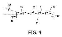
図1には、面を照明するための照明デバイス10が図示されている。照明デバイス10は、発光素子20と、照明体30とを含んでいる。発光素子20は、照明体30を支持するハウジング部品40の下に配されている。図示されている実施形態では、照明デバイス10は読書用ライトであり、照明体30の下に横たわる概ね平坦な面、たとえば本のページ等を照明するのに用いられる。他の人の邪魔をする可能性を減らすため、照明されている面を超える人工光21の照射は、最小限に抑えられなくてはならない。この目的を達成するため、照明体30は光抽出層50を含んでおり、この光抽出層50は、発光素子20から人工光21を受光して、照明対象の面上に向かって方向変換させるように構成されている。 FIG. 1 illustrates an
発光素子20はLEDであり、人工光21を、照明体30に注入する。発光素子20は支持部品40に接続されており、この支持部品40はプリント回路基板(PCB)であってもよい。かかるプリント回路基板は、非導電性の基板上にラミネートされた銅製シートからエッチング形成された導電路を用いて、電子部品を電気的に接続し、かつ機械的に支持するために用いられる。かかる構造は、コストが低くかつ信頼性の高い構造として知られている。さらに、LEDは、PCBの助けを借りて、電子部品に直接接続され得る。ハウジング部品40の、発光素子20と反対側の面には、ドライバ62およびバッテリー61が取り付けられている。バッテリー61は、好ましくは再充電可能なものとされ、必要な電流を発光素子20に供給する。ドライバ62は、電流増幅回路、および所望の波形を出力する波形生成制御回路を含んでいてもよい。また、波形の振幅、周波数およびデューティー比も、波形生成制御回路により調整される。 The
電力を得るのが困難または高コストであるような地球上の地域において照明デバイス10を使用するため、ハウジング部品40上に、太陽電池60が組み込まれてもよい。太陽電池60は、太陽光からの光子を、再充電可能なバッテリー61に貯蔵される電力に変換する。そのため、日中に照明デバイス10が太陽光に曝されれば、暗い場所で照明デバイス10を使用することができる。太陽電池60を利用しているにもかかわらず長時間に亘って面を照明することができるような照明デバイス10を得るには、電力消費量の低い発光素子20が必要とされる。LEDは、低い電力消費量で十分な光レベルを実現するので、適切な発光素子であることが分かっている。 A
前述のように、本発明の目的は、面(図示の実施形態では照明体30の下に配されている面)の均一な照明である。照明体30の側面36に配された単一の発光素子20から人工光21が注入されると、この人工光21は、矢印21'で示すように下面35を介して照明体30から出射するように、方向変換されなくてはならない。この目的を達成するために、光抽出層50が、照明体30の上面に設けられている。図示の実施形態では、光抽出層50および照明体30は一体であり、同一の材料から作られている。 As described above, an object of the present invention is uniform illumination of a surface (a surface disposed under the
図2には、照明デバイス10を上から見た図が示されている。照明デバイス10により照明される面は、図の紙面内にある。10mW未満の電力消費量を有するLEDを用いても、照明レベルは少なくとも25ルクスに到達すべきである。したがって、照明体30のサイズが限られているのは適切である。照明体30は、好ましくは30mmと150mmとの間の長さ32を有し、さらに好ましくは50mmと100mmとの間の長さ32を有する。加えて、1つのLEDのみを用いた照明の場合、照明体30は、好ましくは5mmと40mmとの間の幅33を有し、さらに好ましくは10mmと20mmとの間の幅33を有するべきである。この照明体30の長さ32および幅33は、最大で100cm2、より好ましくは50cm2未満、最も好ましくは10cm2未満のサイズをもたらすであろう。加えて、照明体30の高さは、40mmを超えるべきではなく、さらに好ましくは10mmを超えるべきではなく、最も好ましくは5mmを超えるべきではない。照明体30の最小高さは、使用されるLEDの寸法によって決まる。照明体30に人工光21を注入するのに1つより多くのLEDを使用する形態も、本発明の一部であることは明らかである。The figure which looked at the illuminating
面上に向けて方向変換されずに周囲に散乱される人工光21の量を減らすため、本発明は、光抽出層50を開示する。この光抽出層50の構成が、照明体30のみを図示した図3および4に示されている。人工光21は、左側から照明体30内に注入される。照明体30の下に配された面に向けて人工光21を方向変換するため、光抽出層50は、表面構造を有している。この表面構造は、連続的に配された複数の方向変換手段51を含んでいる。図4には、照明体30の断面拡大図が示されている。人工光21は、左側から照明体30に入射する。各方向変換手段51は、照明体30から急角度で立ち上がる縁53を有する、鋸歯様の断面を有する。これに続き、方向変換手段51は、発光素子20までの距離が大きくなるにつれて下方に傾斜していく面52を有する。こうして、三角形状を有する鋸歯様の構造が構築される。面52は、照明体30の長手延在方向に対して測定される角度として、角度54を有する。人工光21の波長、および照明体30に使用されている材料の屈折率に応じて、角度54は、0.1°から5°の間の角度、好ましくは0.25°と2°との間の角度とされるべきである。周辺大気の屈折率は、照明体30の材料の屈折率と異なるので、内部全反射が生じる。こうして、大気と照明体30/光抽出層50との界面に突き当たる人工光21が、反射され、主として下面35を介して照明体30から出射するようになすことができる。方向変換手段51は、図示されている鋸歯様の構造のほか、複数の異なる断面を有し得る。重要なのは、ミラー様の方向変換領域が確立されるように、面52が、発光素子20に対して角度54で配されるという点のみである。 In order to reduce the amount of artificial light 21 that is scattered around without being redirected towards the surface, the present invention discloses a
図5および6には、照明デバイス10の別の実施形態が示されている。この照明デバイス10は、ハウジング部品40内に配された、再充電可能なコイン型バッテリー61を有している。照明デバイス10をオン状態およびオフ状態に切り換えるため、ハウジング部品40の一端にスイッチ65が取り付けられている。この実施形態は、コイン型電池を用いることにより、照明デバイス10全体の厚さが薄くされるという利点を有する。したがって、スイッチ65を押して、便利な態様で照明デバイス10をアクティブ化することが可能である。この照明デバイス10に対して、太陽電池60は薄片状の構造であるので、全体の高さにはわずかしか寄与しない。上記で述べた実施形態と同様に、光抽出層50と照明体30とは一体であり、ポリマー製の導光プレートといったような有機材料で構築されている。最後に挙げたプレートは透明であり、可視波長領域中の光に対しては、低い減衰率を有する。さらに、ポリマープレートから作られた照明体30には、簡単に発光材料をドーピングすることができる。これらの発光材料は、人工光21を吸収し、異なる波長で再発射することができる。さらに、この発光材料は、発光素子20により発せられた人工光21の散乱に寄与することができる。この散乱は、照明対象の面上に向けて方向変換される、追加の光成分をもたらす。 In FIGS. 5 and 6, another embodiment of the
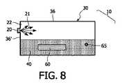
図7には、照明デバイス10の別の実施形態が示されている。上記で説明した照明デバイス10と異なり、スイッチ65が、ハウジング部品40の側面の1つに配されている。この配置は、照明デバイス10の使用の利便性を高める。さらに、照明体30の上に、太陽電池60が配置されている。照明体30により覆われた文面を見るため、照明体30および光抽出層50は、面により反射される人工光21に対して透明でなくてはならない。この特性を得るためには、光抽出層50を覆う太陽電池60も、人工光21に対して透明でなくてはならない。グレッツェル・セルのような光電気化学電池を用いることにより、透明な太陽電池60を確立することができる。この実施形態は、ハウジング部品40のサイズを、大幅に減らすことができるという利点を有する。太陽電池60が照明体30をカバーしており、残りの部品(たとえばバッテリー61、発光素子20)は太陽電池60に比べてサイズが小さいので、大きなハウジング部品40は必要ない。さらに、照明デバイス10は、湿度等の周辺環境の影響からその照明デバイス10を保護する、カバー部品70を有するものとされている。カバー部品70は、ハウジング部品40および/または照明体30の一部を被覆する、ゴムで作られたものであってもよい。 In FIG. 7, another embodiment of the
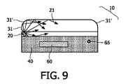
図8には、照明デバイス10の別の実施形態が示されている。上記で述べた実施形態と異なり、ハウジング部品40は、長方形状の照明体30の長い方の側面36のうちの1つに配されている。発光素子20は、照明体30の小さい方の側面36'のうちの1つに配されている。照明デバイス10は、上記で既に述べたような太陽電池60およびスイッチ65を備えている。発光素子20が照明体30の小さい方の側面36'のうちの1つに配されていること、および発光素子20により発せられる光の発散度合いが限られていることに起因して、人工光21は、暗い領域22を残した円錐状の分布を有するものとなる。人工光21のうちほんのわずかな量のみが、照明体30内部における散乱に起因して、この暗い領域22に到達する。この邪魔な暗い領域22を減らすため、発光素子20は、図9に示すように、照明体30の角のうちの1つ31に取り付けられてもよい。この実施形態では、照明体30の角31に、30°から60°の角度で切欠きが形成されている。加えて、より均一な照明パターンを付与するため、残りの角31'は丸められている。図から見て取れるように、人工光21により照明体30内部に生じる暗い領域22は、一切なくなる。一方、照明体30の極めて均一な照明が形成され、ユーザーは、照明体30でカバーされた文面を利便性よく読むことが可能となる。 In FIG. 8, another embodiment of the
照明体30は、その照明体30の下面35に対してほぼ平行に伝搬する光21を吸収して、この光を入射方向と異なる方向に再出射するため、発光材料37を含んでいてもよい。発光材料が光を等方的に発するものであれば、この条件はほとんど常に満たされる。異方性の放射を有する発光粒子を用いる場合には、再出射する光の角度分布を、下面35に向けてさらに整列させてもよい。発光材料37は、照明体30内に均等に分散させられてもよいし、かつ/または図10に示すように空洞38の中に配されてもよい。これらの空洞はいかなる形状であってもよく、図10に示した側面図の長方形状の形状は、可能な例の1つにすぎない。発光材料は、少なくとも1つまたは複数の発光素子20により発せられる光のスペクトル範囲内において、強い吸収性を有する材料とされるべきである。発光材料37の可能性のある例としては、BASF社製の有機ルモゲン(lumogen)、またはY3Al5O12:Ceもしくは(Sr,Ba)2SiO4:Euといった無機材料が挙げられる。材料37は、照明体30に容易に溶け込ませることのできる有機材料であることが好ましい。可視スペクトル全体に含まれる波長で発光材料が光を再出射することを可能とするため、発光素子の少なくともいくつかは、青色および/または近紫外光を発するものとされてもよい。均一な白色光を得るため、発光材料の量は、発光素子までの距離および照明体の形状の関数として、慎重に調整されなくてはならない。発光材料を利用して、照明体30を出射する光21の色として、いかなる所望の色を得ることもできる。ユーザーの注意をより喚起し、ユーザーをより良好に覚醒状態に保つため、コールドブルー色の光21を発するべく、材料37の量および光学特性を調整することが好ましい。冷光が直接ユーザーに到達するのを防止するため、空洞38の光抽出層50に対向した面を、反射層39で覆ってもよい。照明対象の面から反射される光を著しく妨害しないよう、空洞38の大きさは、ユーザーに視認されない程度に十分小さくなくてはならない。The illuminating
反射器部品90'とミラー部品94とを伴う照明体30が、図11に図示されている。テーブルランプ様のデバイスとして照明デバイスを動作させるためには、反射器部品90'は不可欠である。ミラー部品94は、対象物を照明するために反射器部品90'から反射される光21'の輝度を高めるため、照明デバイス10に追加され得る。反射器部品は、照明体30の下面35を介して照明体30から出射する光21の少なくとも一部を、光21'で照明されるべき対象物に向けて反射する。反射光21'の量は、照明体30ならびに反射器部品90'の幾何学特性、および下面35に対する反射器部品90'の反射面の角度位置に依存する。光21'の輝度を高めるため、ミラー部品94が、光抽出層50の上に配されてもよい。照明体30内を伝搬する光の一部は、光抽出層50の表面を介して、照明体30から出射する。本例のミラー部品94がない場合、この光は、反射器部品90'により反射されない。本例のミラー部品94は、この光21を、照明体30内に戻し、下面35を介して照明体30から出射させるように反射する。ミラー部品は、照明体から所定距離だけ離間されて配されてもよい。しかしながら、コンパクトなデバイスを提供するため、この距離は小さな距離とされるべきである。あるいは、ミラー部品94は、光抽出層50に直接接するように配されてもよい。1つの好ましい実施形態では、ミラー部品94は、光抽出層50の上面に適合するように、光抽出層50の表面構造51、52、53に適合させられた表面構造を呈するものとされる。
読書用ランプおよびニーズによってテーブルランプ様のデバイスとして照明デバイスを動作させられるようにするためには、ミラー部品94は、リバーシブルな態様で、照明体30、ハウジング40および/または反射器部品90'に取り付けられるべきである。ミラー部品94のリバーシブル態様の取付けは、(光学素子の取付けに関して)図15に示すクリップ手段92、93のような機械的手段、もしくはその他の機械的解決策により実現されてもよいし、ミラー部品94の接着性表面を通じて実現されてもよい。当業者であれば、これらに代わる取付手段も考えるであろう。 In order to be able to operate the lighting device as a table lamp-like device depending on the reading lamp and needs, the
図12は、反射器部品90'につき2つの異なる位置を有する、テーブルランプ様のデバイスとしての照明デバイス10を示している。ニーズによって読書用ランプおよびテーブルランプ様のデバイスとして照明デバイス10を使用するためには、ハウジング40の形状は、図12に示したような垂直配置で照明デバイス10を安定して配置させるのに適した形状とされるべきである。この配置は、ハウジング40の台座部分のサイズを十分大きくすること、および/または、照明体30、反射器部品90'、ならびにオプションとしてミラー部品94といった付属部品と比較して、ハウジングの重量を十分重くすることにより実現され得る。光21'により照明される領域を調整するため、反射器部品90'は、たとえば反射器部品90'と照明体30との間の角度を所望の値に調整できるよう両部品の間に取り付けられたヒンジ等の手段により、調整可能な態様で照明デバイス10に取り付けられる。当業者であれば、反射器部品90'と照明デバイス10(好ましくは照明体30)との間で調整可能な角度を可能とする、他の調整可能な取付態様も考えるであろう。下面35と反射器部品90'の表面との間の角度は、0と360°との間で変化してもよく、好ましくは0と180°との間、さらに好ましくは90°と180°との間で変化してもよい。 FIG. 12 shows the
別の実施形態では、照明体から出射する人工光21、21'の少なくとも一部を受光し、その光を別の方向に向けて方向変換するように構成された反射器部品90'の反射面が、照明体30の下面35に直接接するように配置されてもよい。この構成では、光21は、下面35とは反対側の光抽出層50の表面を介して照明体30から出射するよう、光抽出層50に向けて反射される。この場合(ミラー部品94がなければ)、照明デバイス10は、反射器部品90'の反射面により覆われていない下面35を介して照明体30から出射する光21によって、対象物を照明する読書用ランプとして、かつ、反射器部品90'の反射面により覆われている下面35と反対側の面を介して照明体30から出射する光21によって、他の照明目的(たとえば室内照明)を担う光源として、同時に動作する。 In another embodiment, the reflecting surface of the
1つの変更実施形態では、上記で述べたのと同様の機能が、下面35の一部に固定して配されたミラーであって、透明モードと反射モードとの間で切換可能なミラーを用いて実現され得る。かかる切換可能なミラーは、たとえば、電気的に切換可能な液晶層とされる。何らかの発光素子20により発せられる青色および/またはUV光により、ルミネッセント紙が照射を受ける場合には、光抽出層の表面を介して発せられる光のエフェクトは、書込目的のためにさらに高められてもよい。 In one modified embodiment, a function similar to that described above is a mirror that is fixedly arranged on a part of the
図13は、ミクロ構造が付与された、または湾曲させられた、またはセグメント化された反射器部品90'といったような、反射器部品90'の複数の異なる可能な形状の例を示している。(ここには図示していないが、)平面形状もまた可能である。 FIG. 13 shows an example of a plurality of different possible shapes of a
図14には、集光部品90の効果が図示されている。人工光21が、左側から照明体30に入光している。人工光21の一部は、光抽出層50を通り、照明体30の上面から出射する。人工光21の別の一部は、縁において光抽出層50により方向変換させられ、小さな角度をもって、照明体30の下面35から出射する。人工光21の第3の部分は、照明体30の側面36から出射する。したがって、人工光21の最後に述べた部分と、集光部品90のサイズによっては最後より1つ前に述べた部分のうちのわずかな部分とが、集光部品90に入光する。集光部品90は導光性材料を含んでいるので、人工光21は減衰されない。集光部品90の外表面は、集められた人工光21を受光し方向変換するための、表面形状91を含んでいる。表面形状91は、集光部品90から出射する人工光21'の光束の形状を、集光光束または(図示されているような)平行光束に整形する機能を有する。したがって、照明デバイス10は、トーチとして使用され得る。 FIG. 14 illustrates the effect of the
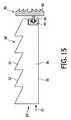
照明デバイス10をトーチとして使用する可能性を実現するための、集光部品90を開示する。図15には、照明体30の長手方向の側面36に接続される、集光部品90の断面図が図示されている。照明体30に注入され、光抽出層50によっては全くあるいはわずかしか方向変換されない人工光21は、意図したように面101を照明することなく、照明体30から出射するかもしれない。人工光21のこの部分を利用するために、集光部品90は、人工光21の少なくとも一部を受光し方向付けるように構成された、導光性材料を含んでいる。したがって、集光部品90は、図示の例では鋸歯様の構造を有する、表面形状91を含むものとされている。この表面形状91は、集光部品90から出射する人工光を集光させるために、フレネル型のレンズを形成してもよい。さらに、集光部品90はクリップ手段92を含んでいてもよく、このクリップ手段92は、照明体30の第2のクリップ手段93と協働する。クリップ手段92と第2のクリップ手段93との接続によって、集光部品90は、照明体30に対してリバーシブルに取付可能とされている。 A
10 照明デバイス
20 発光素子
21、21' 人工光
22 暗い領域
30 照明体
31、31' 照明体30の角
32 照明体30の長さ
33 照明体30の幅
35 照明体30の下面
36、36' 照明体30の側面
37 発光材料
38 空洞
39 反射層
40 ハウジング部品
50 光抽出層
51 方向変換手段
52 方向変換手段51の面
53 方向変換手段51の縁
54 角度
60 太陽電池
61 バッテリー
62 ドライバ
65 スイッチ
70 カバー部品
90 集光部品
90' 反射器部品
91 表面形状
92 クリップ手段
93 第2のクリップ手段
94 ミラー部品DESCRIPTION OF
Claims (18)
Translated fromJapanese前記発光素子が人工光を発し、
ハウジング部品が、前記発光素子を包含し、かつ前記照明体を支持しており、
前記照明体は、該照明体の下に横たわる前記面を照明するのに適した、透明な導光性材料を含んでおり、
前記照明体は、前記発光素子から前記人工光を受光し、該人工光を前記面上に向けて方向変換するように構成された、光抽出層を含んでおり、
当該照明デバイスはさらに、光学素子を含んでおり、該光学素子が、前記照明体の長手方向の側面に配されており、前記照明体から出射する前記人工光の少なくとも一部を、受光し、照明されるべき対象物に向けて方向付ける、かつ/または再整形するように構成されていることを特徴とする照明デバイス。An illumination device for illuminating a surface having a light emitting element and an illuminating body,
The light emitting element emits artificial light;
A housing part including the light emitting element and supporting the illuminating body;
The illuminating body comprises a transparent light-guiding material suitable for illuminating the surface lying under the illuminating body;
The illuminating body includes a light extraction layer configured to receive the artificial light from the light emitting element and redirect the artificial light toward the surface,
The illumination device further includes an optical element, the optical element is disposed on a side surface in the longitudinal direction of the illumination body, and receives at least a part of the artificial light emitted from the illumination body, Illumination device configured to direct and / or reshape towards an object to be illuminated.
Applications Claiming Priority (6)
| Application Number | Priority Date | Filing Date | Title |
|---|---|---|---|
| EP07100817.1 | 2007-01-19 | ||
| EP07100817 | 2007-01-19 | ||
| EP07117975.8 | 2007-10-05 | ||
| EP07117975 | 2007-10-05 | ||
| EP07122374.7 | 2007-12-05 | ||
| EP07122374 | 2007-12-05 |
Related Parent Applications (1)
| Application Number | Title | Priority Date | Filing Date |
|---|---|---|---|
| JP2009546039ADivisionJP5554063B2 (en) | 2007-01-19 | 2008-01-16 | Lighting device |
Publications (2)
| Publication Number | Publication Date |
|---|---|
| JP2013235855Atrue JP2013235855A (en) | 2013-11-21 |
| JP5718417B2 JP5718417B2 (en) | 2015-05-13 |
Family
ID=39430750
Family Applications (2)
| Application Number | Title | Priority Date | Filing Date |
|---|---|---|---|
| JP2009546039AExpired - Fee RelatedJP5554063B2 (en) | 2007-01-19 | 2008-01-16 | Lighting device |
| JP2013158024AExpired - Fee RelatedJP5718417B2 (en) | 2007-01-19 | 2013-07-30 | Lighting device |
Family Applications Before (1)
| Application Number | Title | Priority Date | Filing Date |
|---|---|---|---|
| JP2009546039AExpired - Fee RelatedJP5554063B2 (en) | 2007-01-19 | 2008-01-16 | Lighting device |
Country Status (7)
| Country | Link |
|---|---|
| US (1) | US8337034B2 (en) |
| EP (1) | EP2106516A2 (en) |
| JP (2) | JP5554063B2 (en) |
| CN (1) | CN101583823B (en) |
| BR (1) | BRPI0806797A2 (en) |
| TW (1) | TW200907243A (en) |
| WO (1) | WO2008087593A2 (en) |
Cited By (1)
| Publication number | Priority date | Publication date | Assignee | Title |
|---|---|---|---|---|
| WO2022024852A1 (en)* | 2020-07-28 | 2022-02-03 | 日東電工株式会社 | Lighting device |
Families Citing this family (15)
| Publication number | Priority date | Publication date | Assignee | Title |
|---|---|---|---|---|
| KR20110100302A (en) | 2008-12-30 | 2011-09-09 | 코닌클리케 필립스 일렉트로닉스 엔.브이. | Adjustable lighting devices |
| WO2010079439A1 (en)* | 2009-01-09 | 2010-07-15 | Koninklijke Philips Electronics N.V. | Optical element with led, and light source comprising the same |
| TW201243220A (en)* | 2011-03-17 | 2012-11-01 | Rambus Inc | Lighting assembly with adjustable light output |
| CN203023921U (en)* | 2011-09-09 | 2013-06-26 | 柯尼卡美能达先进多层薄膜株式会社 | Lighting device and lighting desk lamp |
| US9976724B2 (en)* | 2012-06-11 | 2018-05-22 | Energizer Brands, Llc | Lighting device construction |
| WO2014085670A1 (en) | 2012-11-30 | 2014-06-05 | Rambus Delaware Llc | Lighting assembly with defined angular output |
| JPWO2014208291A1 (en)* | 2013-06-27 | 2017-02-23 | コニカミノルタ株式会社 | Lighting device |
| US10244603B2 (en) | 2014-09-03 | 2019-03-26 | Lg Display Co., Ltd. | OLED stand |
| JP6358438B2 (en)* | 2015-01-20 | 2018-07-18 | パナソニックIpマネジメント株式会社 | Display illumination device and electric vacuum cleaner provided with the same |
| JP6789837B2 (en)* | 2017-02-08 | 2020-11-25 | 株式会社東海理化電機製作所 | Display device |
| JP6418306B1 (en)* | 2017-11-07 | 2018-11-07 | オムロン株式会社 | Lighting device and display device |
| CH715534A1 (en)* | 2018-11-12 | 2020-05-15 | Regent Beleuchtungskoerper Ag | Optics and table lamp. |
| CN210373003U (en)* | 2019-10-28 | 2020-04-21 | 苏州欧普照明有限公司 | Lamp fitting |
| JP7613674B2 (en)* | 2020-07-28 | 2025-01-15 | 日東電工株式会社 | Lighting equipment |
| KR20240155622A (en)* | 2023-04-20 | 2024-10-29 | 엘지전자 주식회사 | Laundry Treatment Apparatus |
Citations (2)
| Publication number | Priority date | Publication date | Assignee | Title |
|---|---|---|---|---|
| JP2002122861A (en)* | 2000-10-12 | 2002-04-26 | Sharp Corp | Reflective display device and lighting device |
| JP2006073202A (en)* | 2004-08-31 | 2006-03-16 | Nichia Chem Ind Ltd | Light emitting device |
Family Cites Families (34)
| Publication number | Priority date | Publication date | Assignee | Title |
|---|---|---|---|---|
| AU7346281A (en) | 1980-07-25 | 1982-01-28 | Horgan Investments Pty. Ltd. | Viewing unit |
| JPS61103132A (en)* | 1984-10-26 | 1986-05-21 | Olympus Optical Co Ltd | Strobe device with liquid-crystal lens |
| US4816970A (en)* | 1986-10-14 | 1989-03-28 | Garcia Jr Manuel | Solar powered light |
| JPH01175103A (en)* | 1987-12-29 | 1989-07-11 | Fujitsu Ltd | Back light |
| US5050946A (en)* | 1990-09-27 | 1991-09-24 | Compaq Computer Corporation | Faceted light pipe |
| JPH0520908A (en)* | 1991-07-15 | 1993-01-29 | Fuji Electric Co Ltd | Surface illuminated display |
| US5485291A (en)* | 1994-02-22 | 1996-01-16 | Precision Lamp, Inc. | Uniformly thin, high efficiency large area lighting panel with two facet grooves that are spaced apart and have light source facing facets with smaller slopes than the facets facing away from the light source |
| US5486986A (en)* | 1994-03-29 | 1996-01-23 | Brada; Carla R. | Remote control illuminated magnifier |
| CN1162757A (en)* | 1995-03-06 | 1997-10-22 | 株式会社日立制作所 | Liquid crystal display with edge-type backlighting system |
| US5838403A (en)* | 1996-02-14 | 1998-11-17 | Physical Optics Corporation | Liquid crystal display system with internally reflecting waveguide for backlighting and non-Lambertian diffusing |
| JPH09325336A (en)* | 1996-06-03 | 1997-12-16 | Keiji Iimura | Surface type light source device and passive type display device with same |
| JPH1166928A (en)* | 1997-08-22 | 1999-03-09 | Bridgestone Corp | Linear luminous body |
| JP4159059B2 (en)* | 1998-06-05 | 2008-10-01 | シチズン電子株式会社 | Planar light source unit |
| JP2001184923A (en)* | 1999-12-24 | 2001-07-06 | Casio Comput Co Ltd | Light source device |
| NL1015089C2 (en) | 2000-05-02 | 2001-11-05 | Ferdinand Karel Steup | Rechargeable lamp assembly. |
| JP2002100226A (en)* | 2000-09-26 | 2002-04-05 | Tohoku Denshi Kogyo Kk | Surface light emitter |
| US6612713B1 (en)* | 2001-02-07 | 2003-09-02 | World Factory, Inc. | Umbrella apparatus |
| JP3876629B2 (en)* | 2001-02-22 | 2007-02-07 | 松下電工株式会社 | Lighting device |
| US6764192B2 (en)* | 2001-10-01 | 2004-07-20 | Mcchesney Paula | Combination magnifier and illuminator |
| US6951403B2 (en)* | 2001-10-26 | 2005-10-04 | Lightwedge, Llc | Device for illuminating a generally flat surface |
| JP2003215588A (en)* | 2002-01-25 | 2003-07-30 | Kyocera Corp | Reflective liquid crystal display |
| JP2004062139A (en)* | 2002-06-07 | 2004-02-26 | Toyoda Gosei Co Ltd | Light guide |
| JP2004093707A (en)* | 2002-08-30 | 2004-03-25 | Sanyo Electric Co Ltd | Solar cell device |
| JP2004171991A (en)* | 2002-11-21 | 2004-06-17 | Sony Corp | Lighting device and display device |
| DE10261543A1 (en) | 2002-12-23 | 2004-07-01 | Carl Zeiss | magnifying glass |
| US20040212985A1 (en)* | 2003-04-28 | 2004-10-28 | Travis Robert J. | Electro luminescent and or magnifying bookmark |
| US20050185398A1 (en)* | 2004-02-20 | 2005-08-25 | Scannell Robert F.Jr. | Multifunction-adaptable, multicomponent devices |
| JP2005259536A (en)* | 2004-03-11 | 2005-09-22 | Itoki Corp | Rod-shaped illuminator and display device using the same |
| US7139136B2 (en)* | 2004-03-29 | 2006-11-21 | Menu Mate, Llc | Handheld illuminating magnifier |
| FI20041072L (en) | 2004-04-05 | 2005-10-06 | Ralf Karlsson | A utility item equipped with a lamp |
| JP3817560B2 (en)* | 2004-06-02 | 2006-09-06 | 浜松ホトニクス株式会社 | Lens holder, light guide device, and light irradiation device |
| JP2005347208A (en)* | 2004-06-07 | 2005-12-15 | Toyota Industries Corp | Flat light source device |
| JP3110685U (en)* | 2005-02-28 | 2005-06-30 | 日幸電子工業株式会社 | lighting equipment |
| CH698506B1 (en) | 2006-04-21 | 2009-08-31 | Ribag Licht Ag | Lamp. |
- 2008
- 2008-01-16BRBRPI0806797-0Apatent/BRPI0806797A2/ennot_activeIP Right Cessation
- 2008-01-16WOPCT/IB2008/050139patent/WO2008087593A2/enactiveApplication Filing
- 2008-01-16JPJP2009546039Apatent/JP5554063B2/ennot_activeExpired - Fee Related
- 2008-01-16EPEP08702436Apatent/EP2106516A2/ennot_activeWithdrawn
- 2008-01-16CNCN200880002657.4Apatent/CN101583823B/ennot_activeExpired - Fee Related
- 2008-01-16USUS12/522,740patent/US8337034B2/ennot_activeExpired - Fee Related
- 2008-01-17TWTW097101835Apatent/TW200907243A/enunknown
- 2013
- 2013-07-30JPJP2013158024Apatent/JP5718417B2/ennot_activeExpired - Fee Related
Patent Citations (2)
| Publication number | Priority date | Publication date | Assignee | Title |
|---|---|---|---|---|
| JP2002122861A (en)* | 2000-10-12 | 2002-04-26 | Sharp Corp | Reflective display device and lighting device |
| JP2006073202A (en)* | 2004-08-31 | 2006-03-16 | Nichia Chem Ind Ltd | Light emitting device |
Cited By (1)
| Publication number | Priority date | Publication date | Assignee | Title |
|---|---|---|---|---|
| WO2022024852A1 (en)* | 2020-07-28 | 2022-02-03 | 日東電工株式会社 | Lighting device |
Also Published As
| Publication number | Publication date |
|---|---|
| JP2010517214A (en) | 2010-05-20 |
| BRPI0806797A2 (en) | 2011-09-13 |
| US20100296264A1 (en) | 2010-11-25 |
| US8337034B2 (en) | 2012-12-25 |
| WO2008087593A2 (en) | 2008-07-24 |
| CN101583823B (en) | 2016-05-11 |
| CN101583823A (en) | 2009-11-18 |
| JP5554063B2 (en) | 2014-07-23 |
| JP5718417B2 (en) | 2015-05-13 |
| WO2008087593A3 (en) | 2008-11-27 |
| EP2106516A2 (en) | 2009-10-07 |
| TW200907243A (en) | 2009-02-16 |
Similar Documents
| Publication | Publication Date | Title |
|---|---|---|
| JP5718417B2 (en) | Lighting device | |
| JP5376339B2 (en) | lighting equipment | |
| CN100402774C (en) | Light-emitting blocks using solar cells | |
| CN101652877B (en) | Light emitting device | |
| RU2435249C2 (en) | Illumination device | |
| US20030081407A1 (en) | Device for illuminating a generally flat surface | |
| RU2538756C2 (en) | Solar powered lighting installation | |
| JP2007317360A (en) | Weathertight structure | |
| GB2412724A (en) | LED headlamp with different light intensity modules | |
| CN101929647B (en) | Illuminator | |
| US20110255264A1 (en) | Light emitting module and optical wavelength converting member | |
| RU2464597C2 (en) | Illumination device | |
| EP1983257A1 (en) | Illumination device | |
| KR102701165B1 (en) | Led lighting device having solar panel | |
| TW201332132A (en) | Light-collecting unit, photoelectric apparatus and light-emitting apparatus | |
| CN201772287U (en) | Light-emitting device for increasing light extraction efficiency by destroying total reflection light source | |
| CN210291511U (en) | Searchlight for illumination | |
| JP3144194U (en) | LED lighting fixtures | |
| KR101455153B1 (en) | Lighting device | |
| JP3172381U (en) | Direct light emitting diode lighting lamp unit | |
| TW201100722A (en) | Illumination device | |
| KR20200069438A (en) | Lighting apparatus for High Power Illuminator and optical apparatus therefor | |
| TW201221835A (en) | Lighting device | |
| CN101943347A (en) | Lighting device |
Legal Events
| Date | Code | Title | Description |
|---|---|---|---|
| A131 | Notification of reasons for refusal | Free format text:JAPANESE INTERMEDIATE CODE: A131 Effective date:20140626 | |
| A521 | Request for written amendment filed | Free format text:JAPANESE INTERMEDIATE CODE: A523 Effective date:20140925 | |
| TRDD | Decision of grant or rejection written | ||
| A01 | Written decision to grant a patent or to grant a registration (utility model) | Free format text:JAPANESE INTERMEDIATE CODE: A01 Effective date:20150217 | |
| A61 | First payment of annual fees (during grant procedure) | Free format text:JAPANESE INTERMEDIATE CODE: A61 Effective date:20150318 | |
| R150 | Certificate of patent or registration of utility model | Ref document number:5718417 Country of ref document:JP Free format text:JAPANESE INTERMEDIATE CODE: R150 | |
| S111 | Request for change of ownership or part of ownership | Free format text:JAPANESE INTERMEDIATE CODE: R313113 | |
| R350 | Written notification of registration of transfer | Free format text:JAPANESE INTERMEDIATE CODE: R350 | |
| LAPS | Cancellation because of no payment of annual fees |