JP2013232356A - Coiled cable - Google Patents
Coiled cableDownload PDFInfo
- Publication number
- JP2013232356A JP2013232356AJP2012104235AJP2012104235AJP2013232356AJP 2013232356 AJP2013232356 AJP 2013232356AJP 2012104235 AJP2012104235 AJP 2012104235AJP 2012104235 AJP2012104235 AJP 2012104235AJP 2013232356 AJP2013232356 AJP 2013232356A
- Authority
- JP
- Japan
- Prior art keywords
- conductor
- coil
- coiled cable
- coiled
- diameter
- Prior art date
- Legal status (The legal status is an assumption and is not a legal conclusion. Google has not performed a legal analysis and makes no representation as to the accuracy of the status listed.)
- Pending
Links
- 239000004020conductorSubstances0.000claimsabstractdescription112
- 239000000463materialSubstances0.000claimsabstractdescription15
- 239000011247coating layerSubstances0.000claimsabstractdescription14
- 238000004804windingMethods0.000claimsabstractdescription5
- 239000010410layerSubstances0.000claimsdescription26
- 239000012212insulatorSubstances0.000claimsdescription8
- 229920000840ethylene tetrafluoroethylene copolymerPolymers0.000claimsdescription6
- -1perfluoroalkyl vinyl etherChemical compound0.000claimsdescription6
- 230000002093peripheral effectEffects0.000claimsdescription6
- 229920001343polytetrafluoroethylenePolymers0.000claimsdescription6
- 239000004810polytetrafluoroethyleneSubstances0.000claimsdescription6
- 229920005989resinPolymers0.000claimsdescription4
- 239000011347resinSubstances0.000claimsdescription4
- 229920006026co-polymeric resinPolymers0.000claimsdescription3
- 229920001577copolymerPolymers0.000claimsdescription3
- 239000011253protective coatingSubstances0.000claimsdescription3
- BFKJFAAPBSQJPD-UHFFFAOYSA-NtetrafluoroetheneChemical groupFC(F)=C(F)FBFKJFAAPBSQJPD-UHFFFAOYSA-N0.000claimsdescription3
- RYGMFSIKBFXOCR-UHFFFAOYSA-NCopperChemical compound[Cu]RYGMFSIKBFXOCR-UHFFFAOYSA-N0.000abstractdescription14
- 229910052802copperInorganic materials0.000abstractdescription14
- 239000010949copperSubstances0.000abstractdescription14
- 229910000881Cu alloyInorganic materials0.000abstractdescription13
- 238000009413insulationMethods0.000abstractdescription2
- 238000005452bendingMethods0.000description22
- 230000000052comparative effectEffects0.000description19
- 230000000694effectsEffects0.000description6
- ATJFFYVFTNAWJD-UHFFFAOYSA-NTinChemical compound[Sn]ATJFFYVFTNAWJD-UHFFFAOYSA-N0.000description5
- BQCADISMDOOEFD-UHFFFAOYSA-NSilverChemical compound[Ag]BQCADISMDOOEFD-UHFFFAOYSA-N0.000description3
- 239000007943implantSubstances0.000description3
- 229910052709silverInorganic materials0.000description3
- 239000004332silverSubstances0.000description3
- 229910045601alloyInorganic materials0.000description2
- 239000000956alloySubstances0.000description2
- 229910017052cobaltInorganic materials0.000description2
- 239000010941cobaltSubstances0.000description2
- GUTLYIVDDKVIGB-UHFFFAOYSA-Ncobalt atomChemical compound[Co]GUTLYIVDDKVIGB-UHFFFAOYSA-N0.000description2
- 230000000737periodic effectEffects0.000description2
- 239000010935stainless steelSubstances0.000description2
- 229910001220stainless steelInorganic materials0.000description2
- JOYRKODLDBILNP-UHFFFAOYSA-NEthyl urethaneChemical compoundCCOC(N)=OJOYRKODLDBILNP-UHFFFAOYSA-N0.000description1
- 238000001125extrusionMethods0.000description1
- XUCNUKMRBVNAPB-UHFFFAOYSA-NfluoroetheneChemical groupFC=CXUCNUKMRBVNAPB-UHFFFAOYSA-N0.000description1
- 238000009434installationMethods0.000description1
- 230000000638stimulationEffects0.000description1
- 239000000126substanceSubstances0.000description1
- 239000013585weight reducing agentSubstances0.000description1
Images


Classifications
- H—ELECTRICITY
- H01—ELECTRIC ELEMENTS
- H01B—CABLES; CONDUCTORS; INSULATORS; SELECTION OF MATERIALS FOR THEIR CONDUCTIVE, INSULATING OR DIELECTRIC PROPERTIES
- H01B7/00—Insulated conductors or cables characterised by their form
- H01B7/04—Flexible cables, conductors, or cords, e.g. trailing cables
- H01B7/048—Flexible cables, conductors, or cords, e.g. trailing cables for implantation into a human or animal body, e.g. pacemaker leads
- A—HUMAN NECESSITIES
- A61—MEDICAL OR VETERINARY SCIENCE; HYGIENE
- A61N—ELECTROTHERAPY; MAGNETOTHERAPY; RADIATION THERAPY; ULTRASOUND THERAPY
- A61N1/00—Electrotherapy; Circuits therefor
- A61N1/02—Details
- A61N1/04—Electrodes
- A61N1/05—Electrodes for implantation or insertion into the body, e.g. heart electrode
- H—ELECTRICITY
- H01—ELECTRIC ELEMENTS
- H01B—CABLES; CONDUCTORS; INSULATORS; SELECTION OF MATERIALS FOR THEIR CONDUCTIVE, INSULATING OR DIELECTRIC PROPERTIES
- H01B3/00—Insulators or insulating bodies characterised by the insulating materials; Selection of materials for their insulating or dielectric properties
- H01B3/18—Insulators or insulating bodies characterised by the insulating materials; Selection of materials for their insulating or dielectric properties mainly consisting of organic substances
- H01B3/30—Insulators or insulating bodies characterised by the insulating materials; Selection of materials for their insulating or dielectric properties mainly consisting of organic substances plastics; resins; waxes
- A—HUMAN NECESSITIES
- A61—MEDICAL OR VETERINARY SCIENCE; HYGIENE
- A61N—ELECTROTHERAPY; MAGNETOTHERAPY; RADIATION THERAPY; ULTRASOUND THERAPY
- A61N1/00—Electrotherapy; Circuits therefor
- A61N1/02—Details
- A61N1/04—Electrodes
- A61N1/05—Electrodes for implantation or insertion into the body, e.g. heart electrode
- A61N1/056—Transvascular endocardial electrode systems
Landscapes
- Health & Medical Sciences (AREA)
- Life Sciences & Earth Sciences (AREA)
- Heart & Thoracic Surgery (AREA)
- Biophysics (AREA)
- Spectroscopy & Molecular Physics (AREA)
- Physics & Mathematics (AREA)
- Biomedical Technology (AREA)
- Radiology & Medical Imaging (AREA)
- Animal Behavior & Ethology (AREA)
- General Health & Medical Sciences (AREA)
- Public Health (AREA)
- Veterinary Medicine (AREA)
- Nuclear Medicine, Radiotherapy & Molecular Imaging (AREA)
- Engineering & Computer Science (AREA)
- Cardiology (AREA)
- Insulated Conductors (AREA)
- Electrotherapy Devices (AREA)
- Communication Cables (AREA)
Abstract
Description
Translated fromJapanese本発明は、医療分野においてインプラントに使用され、あるいは小型ロボット分野において狭小のスペースで使用されるコイル状電気ケーブルに関する。The present invention relates to a coiled electric cable used for implants in the medical field or used in a small space in the small robot field.
例えば、心臓に周期的な電気刺激を与えて心拍動を起こさせるペースメーカに用いられる電気ケーブルや、手足の動きを補助する小型ロボットに用いられる電気ケーブルは、配線部位の動作に合わせて伸縮可能であることは勿論、繰り返し屈曲、ないしは非常に曲率が小さい屈曲に対する耐性が要求されており、かかる耐久性を満足させるため、従来よりコイル形状に巻かれた電気ケーブルが使用されている。For example, electrical cables used for pacemakers that cause periodic heartbeats by causing periodic heart stimulation, and electrical cables used for small robots that assist the movement of limbs can be expanded and contracted according to the movement of the wiring site. Needless to say, resistance to repeated bending or bending with a very small curvature is required, and in order to satisfy such durability, an electric cable wound in a coil shape is conventionally used.
このような従来のコイル状電気ケーブルとして、特許文献1には、複数本の導体基線を並列配置してコイル状に形成したコイル状電気ケーブルが開示されている。導体基線は、銀や銅等でなる中心材の外周にステンレスやコバルト基合金等でなる外部材が一体化されたクラッド構造体と、このクラッド構造体の外周を被覆するフッ素樹脂等でなる絶縁コーティング層とで構成されている。このような導体基線を複数本並列配置してコイル状に形成しているので伸縮可能となり、中心材を銀や銅等で形成しているので低抵抗となり、外部材をステンレスやコバルト基合金等で形成しているので高張力となる。これにより、コイル状電気ケーブルの耐久性を高めるというものである。As such a conventional coiled electric cable, Patent Document 1 discloses a coiled electric cable in which a plurality of conductor base lines are arranged in parallel to form a coil. The conductor base line is composed of a clad structure in which an outer member made of stainless steel or a cobalt base alloy is integrated on the outer periphery of a central material made of silver, copper, or the like, and an insulation made of fluororesin that covers the outer periphery of the clad structure. It consists of a coating layer. Since a plurality of such conductor base lines are arranged in parallel and formed in a coil shape, it can be expanded and contracted, and since the center material is formed of silver, copper, etc., the resistance is low, and the outer member is stainless steel, cobalt base alloy Because it is formed with high tension. Thereby, durability of a coil-shaped electric cable is improved.
しかしながら、上記特許文献1記載のコイル状電気ケーブルでは、耐久性向上のために、いわゆるバネ指数(D/d)を大きく取る必要があり、十分な耐久性を得るためには当該バネ指数(D/d)を7.8以上の値に設定する必要があるとされていた。このためコイル外径が大きくなり、設置スペース、重量、および導体抵抗の上昇や柔軟性の低下という問題を引き起こしていた。However, in the coiled electric cable described in Patent Document 1, it is necessary to increase the so-called spring index (D / d) in order to improve durability, and in order to obtain sufficient durability, the spring index (D / D) had to be set to a value of 7.8 or more. For this reason, the outer diameter of the coil is increased, causing problems such as an increase in installation space, weight, and conductor resistance and a decrease in flexibility.
本発明は、上記のような課題に鑑みなされたものであり、その目的は、従来のコイル状電気ケーブルにおける上述した問題を解決し、耐久性に優れ、外径が小さく、重量が軽く、導体抵抗が低く、かつ柔軟性に優れたコイル状電気ケーブルを提供することにある。 The present invention has been made in view of the above-described problems, and its object is to solve the above-described problems in the conventional coiled electric cable, excellent durability, small outer diameter, light weight, conductor An object of the present invention is to provide a coiled electric cable having low resistance and excellent flexibility.
上記目的達成のため、本発明のコイル状電気ケーブルでは、それぞれ絶縁コーティング層が施された1乃至8本の直径(d)の導体基線をコイル平均径(D)のコイル状に巻回して形成した導体コイルを有するコイル状ケーブルであって、前記導体コイルは、バネ指数(D/d)が2≦D/d≦4となるように設定され、前記導体基線は、φ0.008以上φ0.05以下である導体材料を複数本撚り合わせて構成されていることを特徴としている。また、前記導体基線は、複数本の導体と、絶縁体層を備えた電線であっても良いし、内部導体と、誘電体層と、外部導体層と、保護被膜層とを備えた同軸ケーブルであっても良い。また、絶縁コーティング層がエチレン−テトラフルオロエチレン共重合体(ETFE)、四フッ化エチレン・六フッ化プロピレン共重合体(FEP)、パーフロロアルキルビニルエーテル共重合樹脂(PFA)、ポリテトラフロロエチレン(PTFE)のうちから選択される何れか1又は2以上の材料からなるフッ素樹脂により構成されていることを特徴としている。更に、前記導体コイルの内周面或いは外周面を被覆する被覆層として、伸縮性を有する、硬度ショアA90以下の樹脂層を有しているのが望ましい。In order to achieve the above object, the coiled electric cable of the present invention is formed by winding 1 to 8 diameter (d) conductor base lines each having an insulating coating layer into a coil shape having an average coil diameter (D). The conductor coil is set so that a spring index (D / d) is 2 ≦ D / d ≦ 4, and the conductor base line is φ0.008 or more and φ0. It is characterized by being constituted by twisting a plurality of conductor materials of 05 or less. The conductor base line may be an electric wire including a plurality of conductors and an insulator layer, or a coaxial cable including an inner conductor, a dielectric layer, an outer conductor layer, and a protective coating layer. It may be. Further, the insulating coating layer is made of ethylene-tetrafluoroethylene copolymer (ETFE), tetrafluoroethylene / hexafluoropropylene copolymer (FEP), perfluoroalkyl vinyl ether copolymer resin (PFA), polytetrafluoroethylene ( It is characterized by being made of a fluororesin made of any one or two or more materials selected from PTFE). Furthermore, it is desirable that the coating layer covering the inner or outer peripheral surface of the conductor coil has a stretchable resin layer having a hardness of A Shore A90 or less.
即ち、本発明者は、前記導体基線をφ0.008以上φ0.05以下である導体材料を複数本撚り合わせて構成することで、導体コイルのバネ指数(D/d)が2≦D/d≦4の範囲内であっても、従来のコイル状ケーブルよりもはるかに優れた耐久性が得られ、且つ柔軟性に優れることを見出した。更に、導体コイルのバネ指数(D/d)を2≦D/d≦4の範囲内とすることで、導体抵抗が低いコイル状ケーブルを作製できることを見出した。 これにより、従来のコイル状ケーブルよりも耐久性に優れながらも、より外径が小さく、重量が軽くなる上に、導体抵抗が低く、且つ柔軟性に優れたコイル状電気ケーブルが得られる。That is, the present inventor configures the conductor base line by twisting a plurality of conductor materials having a diameter of φ0.008 or more and φ0.05 or less so that the spring index (D / d) of the conductor coil is 2 ≦ D / d. Even within the range of ≦ 4, it has been found that durability far superior to that of the conventional coiled cable can be obtained and flexibility is excellent. Furthermore, it has been found that a coiled cable with low conductor resistance can be produced by setting the spring index (D / d) of the conductor coil within the range of 2 ≦ D / d ≦ 4. As a result, a coiled electric cable that is superior in durability to the conventional coiled cable, has a smaller outer diameter, is lighter in weight, has low conductor resistance, and is excellent in flexibility.
以下に説明する実施形態は特許請求の範囲に係る発明を限定するものではなく、また実施形態の中で説明されている特徴の組み合わせの全てが本発明の成立に必須であるとは限らない。The embodiments described below do not limit the invention according to the claims, and all combinations of features described in the embodiments are not necessarily essential for the establishment of the present invention.
図1は、本発明の実施形態に係るコイル状ケーブル10を軸直交方向から見た平面図である。本発明の実施形態に係るコイル状ケーブル10は、それぞれ絶縁コーティング層42が施された1乃至8本(図1の例では4本)の直径(d)の素線としての導体基線21〜24をコイル平均径(D)のコイル状に巻回して形成した導体コイル12を有し、この導体コイル12は、バネ指数(D/d)が2≦D/d≦4となるように設定されている。各導体基線21〜24は、φ0.008以上φ0.05以下である導体材料、例えば、タフピッチ銅、無酸素銅、或いは銅合金線から成る材料を複数本撚り合わせて構成されている。以上のように、本発明の実施形態では、図1に示すように、dは、絶縁コーティング層42を除いた素線としての各導体基線21〜24の直径であり、Dは、導体コイル12の平均径であり、D/dが導体コイル12のバネ指数を表すことになる。Dを導体コイル12の平均径としたが、これは導体コイル12のコイル部の外径と内径との平均を意味し、図1から明らかなように、各導体基線21〜24の中心同士を結んだ導体コイル12のコイル部の直径に相当する。FIG. 1 is a plan view of a
また、コイル状ケーブル10は、最終外径Gが、例えば0.82mmの導体コイル12の外周面を被覆するように被覆層16が設けられている。尚、コイル状ケーブル10は、医療分野においてインプラントに使用され、あるいは小型ロボット分野において狭小のスペースで使用される。インプラント分野では、コイル状ケーブル10が、特に細径であり、且つ柔軟性を有することが求められる。尚、各導体基線21〜24は、複数本の導体と、絶縁体層を備えた電線(単純線)であっても良いし、内部導体と、誘電体層と、外部導体層と、保護被膜層とを備えた同軸ケーブルであっても良い。
また、絶縁コーティング層42は、エチレン−テトラフルオロエチレン共重合体(ETFE)、四フッ化エチレン・六フッ化プロピレン共重合体(FEP)、パーフロロアルキルビニルエーテル共重合樹脂(PFA)、又はポリテトラフロロエチレン(PTFE)のうち1種又は2種以上から成るフッ素樹脂により構成されている。
尚、本実施形態のコイル状ケーブル10は、導体コイル12の外周面を被覆する被覆層16として、伸縮性を有する、硬度ショアA90以下の樹脂層を有している。このような樹脂層は、導体コイル12の内周面を被覆するように形成されていても良い。The coiled
The
In addition, the
尚、このような構成のコイル状ケーブル10においては、導体基線21〜24の絶縁コーティング層42は母材がフッ素樹脂であるため、薄肉であっても、生体適合性、耐摩耗性、耐薬品性および耐油性に優れている。In the
次に、実施例として、上述した導体コイルのバネ指数(D/d)を2≦D/d≦4の範囲内で異ならせ、且つ導体基線を、φ0.008以上φ0.05以下である、タフピッチ銅、無酸素銅、又は銅合金線を複数本撚り合わせて構成したコイル状ケーブル10を作製し、導体コイルのバネ指数(D/d)を2≦D/d≦4の範囲外とし、或いは導体基線の構成を異ならせた比較例と共に、それぞれのケーブルの耐久性を調べるために、屈曲試験を行ったので該試験結果について説明する。Next, as an example, the spring index (D / d) of the above-described conductor coil is varied within a range of 2 ≦ D / d ≦ 4, and the conductor base line is φ0.008 or more and φ0.05 or less. A coiled
ここで、本試験に使用した試験用コイル状ケーブル、即ち、実施例のコイル状ケーブルA、B、C及び比較例のコイル状ケーブルD、E、Fは、以下のようにして作製されている。
[実施例A]
図2に実施例Aのコイル状ケーブル10Aを示す。コイル状ケーブル10Aは、いわゆるAWG46の同軸ケーブルタイプであり、図2(A)において、導体コイルのバネ指数(D/d)=3.59となるような寸法構造とした。
また、図2(B)において、中心導体51は、外径0.021mmの銀めっき銀入り銅合金線を4本撚り合わせている。誘電体層52は、PFAを被覆して外径0.117mmに形成している。また、外部導体層53は、導体素線にあたる外径0.025mmの錫めっき錫入り銅合金線を17本横巻きにして形成し、ジャケット層54は、厚さ0.0265mmのFEPからなるジャケットを押出し被覆して外径0.22mmにした。そして、上記ケーブルを4本用いてコイル状に密着巻きし、熱処理を行いヒートセットして、最終外径Gをφ0.82mmに形成している。
[実施例B]
図3に実施例Bのコイル状ケーブル10Bを示す。コイル状ケーブル10Bは、いわゆるAWGG36の単純線タイプであり(19/0.03)、図3(A)において、導体コイルのバネ指数(D/d)=4.00となるような寸法構造とした。
導体61は、外径0.03mmの錫めっき錫入り銅合金線を19本撚り合わせている。また、絶縁体層62は、PFAを被覆して外径0.22mmにした。そして、上記ケーブルを4本用いてコイル状に密着巻きし、熱処理を行いヒートセットして、最終外径Gをφ0.82mmに形成している。
[実施例C]
図4に実施例Cのコイル状ケーブル10Cを示す。コイル状ケーブル10Cは、いわゆるAWGG36の単純線タイプであり(7/0.05))、図4(A)において、導体コイルのバネ指数(D/d)=4.00となるような寸法構造とした。
導体71は、外径0.05mmの錫めっき錫入り銅合金線を7本撚り合わせている。また、絶縁体層72は、PFAを被覆して外径0.22mmにした。そして、上記ケーブルを4本用いてコイル状に密着巻きし、熱処理を行いヒートセットして、最終外径Gをφ0.82mmに形成している。
[比較例D]
図示しない比較例Dのコイル状ケーブルは、いわゆるAWG36の単純線タイプであり(1/0.127)、バネ指数(D/d)=4.72となるような寸法構造とした。導体は、外径0.127mmの錫めっき錫入り銅合金線を用いたが、上述した本発明の実施例と異なり、複数本撚り合わせたものではない。絶縁体層は、PFAを被覆して外径0.22mmにした。そして、上記ケーブルを4本用いてコイル状に密着巻きし、熱処理を行いヒートセットして、最終外径をφ0.82mmに形成している。
[比較例E]
図示しない比較例Eのコイル状ケーブルは、いわゆるAWG35の単純線タイプであり(1/0.14)、バネ指数(D/d)=4.29となるような寸法構造とした。導体は、外径0.14mmの錫めっき錫入り銅合金線を用いたが、上述した本発明の実施例と異なり、複数本撚り合わせたものではない。絶縁体層は、PFAを被覆して外径0.22mmにした。そして、上記ケーブルを4本用いてコイル状に密着巻きし、熱処理を行いヒートセットして、最終外径をφ0.82mmに形成している。
[比較例F]
図示しない比較例Fのコイル状ケーブルは、いわゆるAWG34の単純線タイプであり(1/0.16)、バネ指数(D/d)=3.75となるような寸法構造とした。導体は、外径0.16mmの錫めっき錫入り銅合金線を用いたが、上述した本発明の実施例と異なり、複数本撚り合わせたものではない。絶縁体層は、PFAを被覆して外径0.22mmにした。そして、上記ケーブルを4本用いてコイル状に密着巻きし、熱処理を行いヒートセットして、最終外径をφ0.82mmに形成している。Here, the test coiled cables used in this test, that is, the coiled cables A, B, and C of the example and the coiled cables D, E, and F of the comparative example are manufactured as follows. .
[Example A]
FIG. 2 shows a
In FIG. 2B, the
[Example B]
FIG. 3 shows a
The
[Example C]
FIG. 4 shows a
The
[Comparative Example D]
The coiled cable of Comparative Example D (not shown) is a so-called AWG36 simple line type (1 / 0.127) and has a dimensional structure such that the spring index (D / d) = 4.72. As a conductor, a tin-plated tin-containing copper alloy wire having an outer diameter of 0.127 mm was used. However, unlike the above-described embodiment of the present invention, a plurality of conductors were not twisted together. The insulator layer was coated with PFA to have an outer diameter of 0.22 mm. The four cables are tightly wound in a coil shape, heat-treated and heat-set to form a final outer diameter of φ0.82 mm.
[Comparative Example E]
The coiled cable of Comparative Example E (not shown) is a so-called AWG35 simple line type (1 / 0.14) and has a dimensional structure such that the spring index (D / d) = 4.29. The conductor used was a tin-plated tin-containing copper alloy wire having an outer diameter of 0.14 mm. However, unlike the embodiments of the present invention described above, a plurality of conductors were not twisted together. The insulator layer was coated with PFA to have an outer diameter of 0.22 mm. The four cables are tightly wound in a coil shape, heat-treated and heat-set to form a final outer diameter of φ0.82 mm.
[Comparative Example F]
The coiled cable of Comparative Example F (not shown) is a so-called AWG34 simple line type (1 / 0.16) and has a dimensional structure such that the spring index (D / d) = 3.75. The conductor used was a tin-plated tin-containing copper alloy wire having an outer diameter of 0.16 mm. However, unlike the embodiments of the present invention described above, a plurality of conductors were not twisted together. The insulator layer was coated with PFA to have an outer diameter of 0.22 mm. The four cables are tightly wound in a coil shape, heat-treated and heat-set to form a final outer diameter of φ0.82 mm.
以上の実施例A、B及びCと比較例D、E及びFの各サンプルを3個ずつ準備して、図示しない屈曲試験機にかけることで、ウレタンシース0.1T付の荷重10gfを印加して、 曲げR=2で曲げ角度±90°に両振りする屈曲試験を実施し、断線に至るまでの曲げ回数を調べた。曲げ回数は、3個のサンプルの平均とした。表1に、実施例A、B及びCと比較例D、E及びFについて、それぞれ上述したD(コイル平均径)、d(導体基線の直径)及びD/d(導体コイルのバネ指数)の値を示す。また、表2に、上記屈曲試験の成績を示す。
ここで、表1に示すように、試験用ケーブルA〜Fにおいて、実施例A〜Cと比較例Fは、すべて導体コイルのバネ指数D/dが4以下である。比較例Fが比較例D及びEよりも少ない回数で断線に至ったのは、導体コイルのバネ指数D/dが3.75と小さいため、導体のねじり応力が大きくなるからと解される。しかしながら、実施例Aでは、導体コイルのバネ指数D/dが3.59と比較例Fよりも小さいにも拘わらず、50万回以上の曲げ回数まで断線に至らず、耐えることができている。これは、実施例Aでは、導体基線を、φ0.008以上φ0.05以下である、タフピッチ銅、無酸素銅、又は銅合金線を複数本撚り合わせて構成したコイル状ケーブルとしているからと解される。一方、実施例B及びCにおいても、導体コイルのバネ指数D/dが4.00であり、比較例D(D/d=4.72)、比較例E(D/d=4.29)よりもバネ指数が小さいにも拘わらず、それぞれ60万回以上、40万回以上の曲げ回数まで断線に至らず、耐えることができている。これも、実施例B及びCでは、導体基線を、φ0.008以上φ0.05以下である、タフピッチ銅、無酸素銅、又は銅合金線を複数本撚り合わせて構成したコイル状ケーブルとしているからと解される。Here, as shown in Table 1, in the test cables A to F, in all of Examples A to C and Comparative Example F, the spring index D / d of the conductor coil is 4 or less. It is understood that the reason why the comparative example F is disconnected less than the comparative examples D and E is that the torsional stress of the conductor increases because the spring index D / d of the conductor coil is as small as 3.75. However, in Example A, although the spring index D / d of the conductor coil is 3.59, which is smaller than that of Comparative Example F, it is not broken until the number of bendings is 500,000 times or more, and it can withstand. . This is because in Example A, the conductor base line is a coiled cable formed by twisting a plurality of tough pitch copper, oxygen-free copper, or copper alloy wires having a diameter of φ0.008 to φ0.05. Is done. On the other hand, in Examples B and C, the spring index D / d of the conductor coil is 4.00, and Comparative Example D (D / d = 4.72) and Comparative Example E (D / d = 4.29) In spite of its smaller spring index, it can withstand the bending up to 600,000 times or more and 400,000 times or more, respectively. Also in Examples B and C, the conductor base line is a coiled cable formed by twisting a plurality of tough pitch copper, oxygen-free copper, or copper alloy wires having a diameter of φ0.008 to φ0.05. It is understood.
このように、実施例A、B、Cのコイル状ケーブルでは、導体コイルのバネ指数(D/d)が2≦D/d≦4となる寸法構造により比較的外径が小さく、重量が軽いコイル状ケーブルを製作できる上に、導体基線をφ0.008以上φ0.05以下である、タフピッチ銅、無酸素銅、又は銅合金線を複数本撚り合わせて構成したので、極めて耐久性に優れたコイル状ケーブルとし得る。また、優れた屈曲耐久性を得られるので、たとえ小さい屈曲が作用した場合でも柔軟な特性を有することから、生体内に用いられる場合でも、生体に及ぼす機械的なストレスを軽減することができる。
尚、上述した実施例A、B及びCと比較例D、E及びFそれぞれのバネ定数を測定した結果を表3に示す。
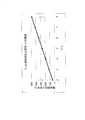
次に、上述したバネ指数(D/d)を2、3、4、5、6、7、8と2乃至8の範囲内で異ならせたコイル状ケーブルに関し、それぞれのバネ指数(D/d)と導体抵抗上昇率(%)の関係をd=0.22となるコイル状ケーブルで計算し、その関係を調べてみた。表4に、それぞれの計算値を示す。
Table 3 shows the results of measuring the spring constants of Examples A, B, and C and Comparative Examples D, E, and F described above.
Next, regarding the coiled cables in which the above-described spring index (D / d) is varied within the range of 2, 3, 4, 5, 6, 7, 8 and 2 to 8, the respective spring indices (D / d) ) And the rate of increase in conductor resistance (%) was calculated using a coiled cable with d = 0.22, and the relationship was examined. Table 4 shows the calculated values.
以上の試験結果や計算結果を詳細に考察すると、例えば、特許文献1記載の従来例では、内部応力の軽減効果を顕著に得るため、7.8≦D/d以上を取る必要があったが、これは「内部応力の軽減」として表記されているが、内部応力とは、曲げる際に導体の内輪側に掛かる圧縮応力と、外輪側に掛かる引張応力を指している。
見かけ上単線として機能するDFT(Drawn Filled Tubing)やDBS(Drawn Brazed Strand)といった導体(図面上からφ0.127:実施例と同じAWG36線)を使用しているため、D/dを大きく取らないと十分な内部応力の軽減効果が得られないからと解される。
本発明では、内部応力の軽減を目的として、D/dを大きくとることなく、細い線径(φ0.008以上、φ0.05以下)の材料を複数本撚り合わせることを特徴としている。
同じ曲げRに対する曲げ応力は、線径の4条に比例して大きくなることから、本発明では、細い線径を用いることで内部応力の軽減が図れることを利用している。
実際は、捻り方向などへの応力分散があるためこの通りの結果とはならないが、内部応力の軽減が図れることは明確である。
実施例にもあるように同じ断面積のAWG36線で比較した結果でも、1/0.127の単線を用いた場合と比較して、φ0.05以下の導体を用いることによって屈曲耐久性が10倍以上に上がることを確認しており、導体コイルのバネ指数を7.8≦D/d以上も取る必要がないことを示している。
このことによって、コイル外径を大幅に細くすることが可能となる。この結果、リード外径が細くなり、生体内で使用する場合は患者への負担を軽減し、患者のQOL向上を図ることが可能となる。また、装置の稼動部で使用した場合は、細径化により配線スペースの軽減が図れる。Considering the above test results and calculation results in detail, for example, in the conventional example described in Patent Document 1, it was necessary to take 7.8 ≦ D / d or more in order to obtain a remarkable effect of reducing internal stress. This is expressed as “reduction of internal stress”, and the internal stress refers to the compressive stress applied to the inner ring side of the conductor and the tensile stress applied to the outer ring side when bending.
Since conductors such as DFT (Drawn Filled Tubing) and DBS (Drawn Brazed Strand) that function as an apparent single wire (φ0.127 from the top of the drawing: the same AWG36 wire as in the embodiment) are used, D / d is not increased. It is understood that sufficient internal stress reduction effect cannot be obtained.
In the present invention, for the purpose of reducing internal stress, a plurality of materials having a thin wire diameter (φ0.008 or more and φ0.05 or less) are twisted together without increasing D / d.
Since the bending stress with respect to the same bending R increases in proportion to the four wire diameters, the present invention utilizes the fact that the internal stress can be reduced by using a thin wire diameter.
Actually, this result is not obtained because there is stress distribution in the twist direction, but it is clear that the internal stress can be reduced.
Even in the result of comparison with the AWG36 wire having the same cross-sectional area as in the example, the bending durability is 10 by using a conductor of φ0.05 or less compared to the case of using a 1 / 0.127 single wire. It is confirmed that the spring index of the conductor coil does not need to be 7.8 ≦ D / d or more.
As a result, the outer diameter of the coil can be significantly reduced. As a result, the lead outer diameter is reduced, and when used in a living body, the burden on the patient can be reduced and the QOL of the patient can be improved. In addition, when used in the operating part of the apparatus, the wiring space can be reduced by reducing the diameter.
コイル巻きに用いられる材料は、D/d=7.8以上をD/d=4.0以下とすることによって、同じ長さのコイルでは材料の必要量が1/2以下に抑えられる。導体抵抗も1/2以下にまで下げることが可能となる。この結果、重量の軽減と、例えばペースメーカーなどで使用した場合、リードの導体抵抗によって熱に変換される電力消費が抑えられるためバッテリー駆動時間の向上を図ることが可能となる。
また、線径を細くする内部応力の軽減効果によって、同じ導体断面積で同じ外径の電線で同様にコイル巻きしたコイルのばね定数は、1/3以下にまで下がることが実験的に得られている。より細い線径で構成されている同軸ケーブルではこの効果がより顕著に現れ、ばね定数が1/10になる実験結果が得られている。
ばね定数が小さいことは、コイルの長手方向のしなやかさとなって現れることが知られている。しなやかであることは、稼動時の負担軽減効果が大きくなり、ペースメーカーなどでは患者への負担軽減や違和感防止に大きく役立つという顕著な効果が得られる。By setting D / d = 7.8 or more to D / d = 4.0 or less as the material used for the coil winding, the necessary amount of material can be suppressed to ½ or less in the same length coil. The conductor resistance can be lowered to 1/2 or less. As a result, weight reduction and, for example, when used in a pacemaker, power consumption converted to heat by the conductor resistance of the lead can be suppressed, so that the battery driving time can be improved.
In addition, it was experimentally obtained that the spring constant of a coil that was similarly coiled with an electric wire having the same outer diameter and the same conductor cross-sectional area was reduced to 1/3 or less due to the effect of reducing internal stress by reducing the wire diameter. ing. This effect is more noticeable in a coaxial cable configured with a thinner wire diameter, and experimental results have been obtained in which the spring constant is 1/10.
It is known that a small spring constant appears as flexibility in the longitudinal direction of the coil. Being supple increases the effect of reducing the burden during operation, and a pacemaker or the like has a remarkable effect of greatly helping to reduce the burden on the patient and preventing discomfort.
尚、上述した実施形態では、コイル状ケーブル10の導体基線は4本並設した構成としたが、導体基線を1本のみコイル状に巻回したもの、或いは2〜8本並設してコイル状に巻回したものでも良い。また、各導体基線は、φ0.008以上φ0.05以下である導体材料を複数本撚り合わせて構成されていれば、撚りあわせ本数は特に限定されるものではない。In the embodiment described above, four conductor base lines of the coiled
本発明のコイル状電線は、極細であるため、例えば、内視鏡のような医療分野、小型携帯コンピュータ、携帯電話等の小型電子機器に適用可能である。Since the coiled electric wire of the present invention is extremely thin, it can be applied, for example, to medical fields such as endoscopes, small electronic devices such as small portable computers and mobile phones.
10 コイル状ケーブル、12 導体コイル、 16 被覆層、 21〜24 導体基線、42 絶縁コーティング層、10 coiled cable, 12 conductor coil, 16 coating layer, 21-24 conductor baseline, 42 insulating coating layer,
Claims (5)
Translated fromJapanese前記導体コイルは、バネ指数(D/d)が2≦D/d≦4となるように設定され、
前記導体基線は、φ0.008以上φ0.05以下である導体材料を複数本撚り合わせて構成されていることを特徴とするコイル状ケーブル。A coiled cable having a conductor coil formed by winding 1 to 8 conductor base lines having a diameter (d) each coated with an insulating coating layer into a coil having a coil average diameter (D),
The conductor coil is set so that the spring index (D / d) is 2 ≦ D / d ≦ 4,
The coiled cable is characterized in that the conductor base line is formed by twisting a plurality of conductor materials having a diameter of φ0.008 or more and φ0.05 or less.
5. The coiled cable according to claim 1, further comprising: a resin layer having a hardness of Shore A 90 or less, having elasticity as a covering layer covering an inner peripheral surface or an outer peripheral surface of the conductor coil. .
Priority Applications (4)
| Application Number | Priority Date | Filing Date | Title |
|---|---|---|---|
| JP2012104235AJP2013232356A (en) | 2012-04-27 | 2012-04-27 | Coiled cable |
| EP13782504.8AEP2843670B1 (en) | 2012-04-27 | 2013-04-22 | Coiled cable |
| PCT/JP2013/061721WO2013161730A1 (en) | 2012-04-27 | 2013-04-22 | Coiled cable |
| US14/395,947US9281100B2 (en) | 2012-04-27 | 2013-04-22 | Coiled cable |
Applications Claiming Priority (1)
| Application Number | Priority Date | Filing Date | Title |
|---|---|---|---|
| JP2012104235AJP2013232356A (en) | 2012-04-27 | 2012-04-27 | Coiled cable |
Publications (1)
| Publication Number | Publication Date |
|---|---|
| JP2013232356Atrue JP2013232356A (en) | 2013-11-14 |
Family
ID=49483047
Family Applications (1)
| Application Number | Title | Priority Date | Filing Date |
|---|---|---|---|
| JP2012104235APendingJP2013232356A (en) | 2012-04-27 | 2012-04-27 | Coiled cable |
Country Status (4)
| Country | Link |
|---|---|
| US (1) | US9281100B2 (en) |
| EP (1) | EP2843670B1 (en) |
| JP (1) | JP2013232356A (en) |
| WO (1) | WO2013161730A1 (en) |
Families Citing this family (3)
| Publication number | Priority date | Publication date | Assignee | Title |
|---|---|---|---|---|
| US10919729B2 (en) | 2014-11-17 | 2021-02-16 | Halliburton Energy Services, Inc. | Self-retractable coiled electrical cable |
| CN109091758A (en)* | 2018-07-18 | 2018-12-28 | 河南正治医疗器械有限公司 | A kind of stimulating coil of magnetic shock treatment instrument |
| CN111653385B (en)* | 2020-07-09 | 2021-08-20 | 浙江万马集团特种电子电缆有限公司 | Ultra-high-elasticity torsion-resistant walkie-talkie spring wire for firefighters and production method thereof |
Citations (5)
| Publication number | Priority date | Publication date | Assignee | Title |
|---|---|---|---|---|
| JPH11333000A (en)* | 1998-05-27 | 1999-12-07 | Cardio Pacing Research Laboratory:Kk | Electrode lead for biological implantation |
| JP2001029480A (en)* | 1999-07-23 | 2001-02-06 | Terumo Corp | Electrode lead implanted in organism |
| WO2010065049A1 (en)* | 2008-12-05 | 2010-06-10 | Cardiac Pacemakers, Inc. | Leads with high surface resistance |
| JP2011504405A (en)* | 2007-12-06 | 2011-02-10 | カーディアック ペースメイカーズ, インコーポレイテッド | Implantable lead with variable coil conductor pitch |
| US20120053665A1 (en)* | 2010-08-25 | 2012-03-01 | Medtronic, Inc. | Fixation components for implantable medical devices and associated device construction |
Family Cites Families (11)
| Publication number | Priority date | Publication date | Assignee | Title |
|---|---|---|---|---|
| US5372138A (en)* | 1988-03-21 | 1994-12-13 | Boston Scientific Corporation | Acousting imaging catheters and the like |
| US4861945A (en)* | 1988-12-09 | 1989-08-29 | Precision Interconnect Corporation | Yieldably extensible self-retracting shielded cable |
| EP0706345B1 (en)* | 1993-07-01 | 2003-02-19 | Boston Scientific Limited | Imaging, electrical potential sensing, and ablation catheters |
| JPH07109556A (en)* | 1993-10-08 | 1995-04-25 | Shinko Kosen Kogyo Kk | Alloy layer coated steel wire and method for producing the same |
| US5483022A (en)* | 1994-04-12 | 1996-01-09 | Ventritex, Inc. | Implantable conductor coil formed from cabled composite wire |
| JPH08138449A (en) | 1994-11-08 | 1996-05-31 | Hitachi Cable Ltd | Spring cable |
| JPH097425A (en) | 1995-06-22 | 1997-01-10 | Bridisco Ltd | Dynamic electric conduction cable |
| US5796044A (en)* | 1997-02-10 | 1998-08-18 | Medtronic, Inc. | Coiled wire conductor insulation for biomedical lead |
| JP2010273912A (en) | 2009-05-29 | 2010-12-09 | Olympus Corp | Medical lead and lead system |
| ES2547713T3 (en) | 2009-06-26 | 2015-10-08 | Cardiac Pacemakers, Inc. | Bypass of a medical device that includes a single-coil coil with improved torque transmission capacity and reduced RM heating |
| JP5345598B2 (en) | 2010-09-01 | 2013-11-20 | 秀雄 西川 | Inspection jig and contact |
- 2012
- 2012-04-27JPJP2012104235Apatent/JP2013232356A/enactivePending
- 2013
- 2013-04-22WOPCT/JP2013/061721patent/WO2013161730A1/enactiveApplication Filing
- 2013-04-22EPEP13782504.8Apatent/EP2843670B1/ennot_activeNot-in-force
- 2013-04-22USUS14/395,947patent/US9281100B2/ennot_activeExpired - Fee Related
Patent Citations (5)
| Publication number | Priority date | Publication date | Assignee | Title |
|---|---|---|---|---|
| JPH11333000A (en)* | 1998-05-27 | 1999-12-07 | Cardio Pacing Research Laboratory:Kk | Electrode lead for biological implantation |
| JP2001029480A (en)* | 1999-07-23 | 2001-02-06 | Terumo Corp | Electrode lead implanted in organism |
| JP2011504405A (en)* | 2007-12-06 | 2011-02-10 | カーディアック ペースメイカーズ, インコーポレイテッド | Implantable lead with variable coil conductor pitch |
| WO2010065049A1 (en)* | 2008-12-05 | 2010-06-10 | Cardiac Pacemakers, Inc. | Leads with high surface resistance |
| US20120053665A1 (en)* | 2010-08-25 | 2012-03-01 | Medtronic, Inc. | Fixation components for implantable medical devices and associated device construction |
Also Published As
| Publication number | Publication date |
|---|---|
| WO2013161730A1 (en) | 2013-10-31 |
| US20150114681A1 (en) | 2015-04-30 |
| EP2843670A1 (en) | 2015-03-04 |
| EP2843670A4 (en) | 2015-12-02 |
| US9281100B2 (en) | 2016-03-08 |
| EP2843670B1 (en) | 2017-11-01 |
Similar Documents
| Publication | Publication Date | Title |
|---|---|---|
| US6374141B1 (en) | Multi-lead bioelectrical stimulus cable | |
| US10249412B2 (en) | Composite cable | |
| CN108538488A (en) | Coaxial cable and cable with braid shielded | |
| JP6893496B2 (en) | coaxial cable | |
| JP4143087B2 (en) | Ultra-fine insulated wire and coaxial cable, manufacturing method thereof, and multi-core cable using the same | |
| WO2013161730A1 (en) | Coiled cable | |
| US9691518B2 (en) | Medical cable | |
| JP2004014337A (en) | Extra-fine multi-core coaxial cable | |
| RU2651874C2 (en) | Mounting electric wire | |
| EP4384260A1 (en) | Braid-supported helical leads for implantable electrode leads | |
| JP5821892B2 (en) | Multi-core cable and manufacturing method thereof | |
| US9786417B2 (en) | Multi-core cable and method of manufacturing the same | |
| US12230418B2 (en) | Composite cable | |
| CN115910438A (en) | Composite cable | |
| JP6939324B2 (en) | Coaxial wire and multi-core cable | |
| JP2010257688A (en) | Electric wire coating material | |
| JP6009253B2 (en) | Coaxial cable for high-frequency power transmission | |
| JP2010273912A (en) | Medical lead and lead system | |
| JP2010257687A (en) | Coiled electric wire | |
| JP6089071B2 (en) | Headphone cable | |
| CN203826026U (en) | Electric wire | |
| CN108766633A (en) | A kind of high flexibility tensile wear-resistant movable flat cable | |
| KR100996545B1 (en) | Multi-segment conductors and power cables with these conductors | |
| JP2017183099A (en) | cable | |
| CN119852015A (en) | Multi-core cable |
Legal Events
| Date | Code | Title | Description |
|---|---|---|---|
| A621 | Written request for application examination | Free format text:JAPANESE INTERMEDIATE CODE: A621 Effective date:20150417 | |
| A131 | Notification of reasons for refusal | Free format text:JAPANESE INTERMEDIATE CODE: A131 Effective date:20160524 | |
| A02 | Decision of refusal | Free format text:JAPANESE INTERMEDIATE CODE: A02 Effective date:20161220 |