JP2013215505A - Medical manipulator - Google Patents
Medical manipulatorDownload PDFInfo
- Publication number
- JP2013215505A JP2013215505AJP2012090797AJP2012090797AJP2013215505AJP 2013215505 AJP2013215505 AJP 2013215505AJP 2012090797 AJP2012090797 AJP 2012090797AJP 2012090797 AJP2012090797 AJP 2012090797AJP 2013215505 AJP2013215505 AJP 2013215505A
- Authority
- JP
- Japan
- Prior art keywords
- unit
- shaft
- drive transmission
- distal end
- opening
- Prior art date
- Legal status (The legal status is an assumption and is not a legal conclusion. Google has not performed a legal analysis and makes no representation as to the accuracy of the status listed.)
- Granted
Links
Images


Classifications
- A—HUMAN NECESSITIES
- A61—MEDICAL OR VETERINARY SCIENCE; HYGIENE
- A61B—DIAGNOSIS; SURGERY; IDENTIFICATION
- A61B17/00—Surgical instruments, devices or methods
- A61B17/28—Surgical forceps
- A61B17/29—Forceps for use in minimally invasive surgery
- A—HUMAN NECESSITIES
- A61—MEDICAL OR VETERINARY SCIENCE; HYGIENE
- A61B—DIAGNOSIS; SURGERY; IDENTIFICATION
- A61B17/00—Surgical instruments, devices or methods
- A61B17/28—Surgical forceps
- A61B17/29—Forceps for use in minimally invasive surgery
- A61B17/2909—Handles
- A—HUMAN NECESSITIES
- A61—MEDICAL OR VETERINARY SCIENCE; HYGIENE
- A61B—DIAGNOSIS; SURGERY; IDENTIFICATION
- A61B17/00—Surgical instruments, devices or methods
- A61B17/00234—Surgical instruments, devices or methods for minimally invasive surgery
- A61B2017/00292—Surgical instruments, devices or methods for minimally invasive surgery mounted on or guided by flexible, e.g. catheter-like, means
- A61B2017/003—Steerable
- A61B2017/00305—Constructional details of the flexible means
- A61B2017/00314—Separate linked members
- A—HUMAN NECESSITIES
- A61—MEDICAL OR VETERINARY SCIENCE; HYGIENE
- A61B—DIAGNOSIS; SURGERY; IDENTIFICATION
- A61B17/00—Surgical instruments, devices or methods
- A61B2017/00367—Details of actuation of instruments, e.g. relations between pushing buttons, or the like, and activation of the tool, working tip, or the like
- A61B2017/00398—Details of actuation of instruments, e.g. relations between pushing buttons, or the like, and activation of the tool, working tip, or the like using powered actuators, e.g. stepper motors, solenoids
- A—HUMAN NECESSITIES
- A61—MEDICAL OR VETERINARY SCIENCE; HYGIENE
- A61B—DIAGNOSIS; SURGERY; IDENTIFICATION
- A61B17/00—Surgical instruments, devices or methods
- A61B2017/00477—Coupling
- A—HUMAN NECESSITIES
- A61—MEDICAL OR VETERINARY SCIENCE; HYGIENE
- A61B—DIAGNOSIS; SURGERY; IDENTIFICATION
- A61B17/00—Surgical instruments, devices or methods
- A61B17/28—Surgical forceps
- A61B17/29—Forceps for use in minimally invasive surgery
- A61B2017/2926—Details of heads or jaws
- A61B2017/2927—Details of heads or jaws the angular position of the head being adjustable with respect to the shaft
- A61B2017/2929—Details of heads or jaws the angular position of the head being adjustable with respect to the shaft with a head rotatable about the longitudinal axis of the shaft
- A—HUMAN NECESSITIES
- A61—MEDICAL OR VETERINARY SCIENCE; HYGIENE
- A61B—DIAGNOSIS; SURGERY; IDENTIFICATION
- A61B17/00—Surgical instruments, devices or methods
- A61B17/28—Surgical forceps
- A61B17/29—Forceps for use in minimally invasive surgery
- A61B2017/2926—Details of heads or jaws
- A61B2017/2932—Transmission of forces to jaw members
- A61B2017/2933—Transmission of forces to jaw members camming or guiding means
- A61B2017/2936—Pins in guiding slots
- A—HUMAN NECESSITIES
- A61—MEDICAL OR VETERINARY SCIENCE; HYGIENE
- A61B—DIAGNOSIS; SURGERY; IDENTIFICATION
- A61B17/00—Surgical instruments, devices or methods
- A61B17/28—Surgical forceps
- A61B17/29—Forceps for use in minimally invasive surgery
- A61B2017/2926—Details of heads or jaws
- A61B2017/2932—Transmission of forces to jaw members
- A61B2017/2939—Details of linkages or pivot points
- A—HUMAN NECESSITIES
- A61—MEDICAL OR VETERINARY SCIENCE; HYGIENE
- A61B—DIAGNOSIS; SURGERY; IDENTIFICATION
- A61B17/00—Surgical instruments, devices or methods
- A61B17/28—Surgical forceps
- A61B17/29—Forceps for use in minimally invasive surgery
- A61B2017/2946—Locking means
- A—HUMAN NECESSITIES
- A61—MEDICAL OR VETERINARY SCIENCE; HYGIENE
- A61B—DIAGNOSIS; SURGERY; IDENTIFICATION
- A61B17/00—Surgical instruments, devices or methods
- A61B17/28—Surgical forceps
- A61B17/29—Forceps for use in minimally invasive surgery
- A61B2017/2947—Pivots
- A—HUMAN NECESSITIES
- A61—MEDICAL OR VETERINARY SCIENCE; HYGIENE
- A61B—DIAGNOSIS; SURGERY; IDENTIFICATION
- A61B34/00—Computer-aided surgery; Manipulators or robots specially adapted for use in surgery
- A61B34/70—Manipulators specially adapted for use in surgery
- A61B34/71—Manipulators operated by drive cable mechanisms
- A61B2034/715—Cable tensioning mechanisms for removing slack
Landscapes
- Health & Medical Sciences (AREA)
- Surgery (AREA)
- Life Sciences & Earth Sciences (AREA)
- Medical Informatics (AREA)
- Nuclear Medicine, Radiotherapy & Molecular Imaging (AREA)
- Engineering & Computer Science (AREA)
- Biomedical Technology (AREA)
- Heart & Thoracic Surgery (AREA)
- Ophthalmology & Optometry (AREA)
- Molecular Biology (AREA)
- Animal Behavior & Ethology (AREA)
- General Health & Medical Sciences (AREA)
- Public Health (AREA)
- Veterinary Medicine (AREA)
- Surgical Instruments (AREA)
- Manipulator (AREA)
Abstract
Translated fromJapaneseDescription
Translated fromJapanese本発明は、外科手術、特に内視鏡下外科手術を行う際に用いられる医療用マニピュレータであって、エンドエフェクタを有する先端動作部を無制限の回転範囲でロール動作させることができる医療用マニピュレータに関する。 The present invention relates to a medical manipulator that is used when performing a surgical operation, in particular, an endoscopic surgical operation, and a medical manipulator that can roll a distal end working unit having an end effector within an unlimited rotation range. .
内視鏡下外科手術(又は腹腔鏡下手術とも呼ばれる。)においては、患者の腹部等に複数の孔を開け、これらの孔にトラカール(筒状の器具)を挿入した後、各トラカールを通して、腹腔鏡(カメラ)と複数の鉗子を体腔内に挿入する。鉗子の先端部には、エンドエフェクタとして、生体組織等を把持するためのグリッパや、鋏、電気メスのブレード等が取り付けられている。 In endoscopic surgery (also called laparoscopic surgery), a plurality of holes are opened in the patient's abdomen, etc., and trocars (tubular instruments) are inserted into these holes, and then through each trocar, A laparoscope (camera) and a plurality of forceps are inserted into the body cavity. A gripper, a scissors, a blade of an electric knife, and the like are attached to the distal end portion of the forceps as an end effector for gripping a living tissue or the like.
腹腔鏡と鉗子を体腔内に挿入したら、腹腔鏡に接続されたモニタに映る腹腔内の様子を見ながら鉗子を操作して手術を行う。このような手術方法は、開腹を必要としないため、患者への負担が少なく、術後の回復や退院までの日数が大幅に低減される。このため、このような手術方法は、適用分野の拡大が期待されている。 After the laparoscope and forceps are inserted into the body cavity, the operation is performed by operating the forceps while observing the inside of the abdominal cavity reflected on a monitor connected to the laparoscope. Since such an operation method does not require laparotomy, the burden on the patient is small, and the number of days until recovery and discharge from the operation is greatly reduced. For this reason, such an operation method is expected to expand the application field.
トラカールから挿入される鉗子として、先端部に関節を持たない一般的な鉗子の他に、先端部に関節を有してエンドエフェクタのロール動作や傾動動作が可能な鉗子、いわゆる医療用マニピュレータの開発が行われている(例えば、下記特許文献1参照)。このような医療用マニピュレータによれば、体腔内で自由度の高い動作が可能であり、手技が容易となり、適用可能な症例が多くなる。 Development of so-called medical manipulators as forceps inserted from trocars, in addition to general forceps that do not have joints at the tip, and those that have joints at the tip and can roll and tilt the end effector (For example, refer to Patent Document 1 below). According to such a medical manipulator, an operation with a high degree of freedom is possible in the body cavity, the procedure becomes easy, and the number of applicable cases increases.
ところで、医療用マニピュレータにおいては、エンドエフェクタを含む先端動作部の自由度が多いとともに可動範囲ができるだけ広い方が望ましい。例えば、先端動作部のロール動作の回転範囲が無制限であれば、結紮等の手技の円滑な遂行に寄与することが期待できる。一方、先端動作部における開閉動作と傾動動作を可能な構造を維持しつつ、さらに回転範囲が無制限のロール動作を可能とする構成を採用した場合、機構が複雑化し易い。 By the way, in the medical manipulator, it is desirable that the distal end working unit including the end effector has a large degree of freedom and that the movable range is as wide as possible. For example, if the rotation range of the roll operation of the tip operation unit is unlimited, it can be expected to contribute to the smooth execution of procedures such as ligation. On the other hand, when a configuration that allows a roll operation with an unlimited rotation range while maintaining a structure that allows an opening / closing operation and a tilting operation in the distal end working unit, the mechanism is likely to be complicated.
本発明はこのような課題を考慮してなされたものであり、先端動作部の機構を複雑化することなく、先端動作部の開閉動作と傾動動作を可能な構造を維持しつつ、回転範囲が無制限のロール動作を可能とする医療用マニピュレータを提供することを目的とする。 The present invention has been made in consideration of such problems, and the rotation range is maintained while maintaining a structure capable of opening and closing and tilting operation of the tip operating unit without complicating the mechanism of the tip operating unit. An object of the present invention is to provide a medical manipulator that enables unlimited roll operation.
上記の目的を達成するため、ハンドルと、前記ハンドルから延出したシャフトと、開閉動作が可能なエンドエフェクタを有し、前記シャフトに対して傾動動作が可能に連結され、且つロール動作が可能な先端動作部と、前記ハンドル側から前記先端動作部へ前記開閉動作のための駆動力を伝達する開閉駆動伝達部と、前記ハンドルから前記先端動作部へ前記ロール動作のための回転力を伝達する回転駆動伝達部と、を備え、前記回転駆動伝達部は、前記シャフトの延在方向に沿って延在し且つ前記シャフト内に回転可能に配置されたロール駆動伝達管と、前記シャフトと前記先端動作部との間の関節部に設けられ前記ロール駆動伝達管と噛み合い且つ前記先端動作部の傾動支点を中心に回転可能な中間部材と、前記先端動作部に設けられ前記中間部材と噛み合い且つロール軸線を中心に回転可能な先端側回転体とを有し、前記開閉駆動伝達部は、前記ロール駆動伝達管の内側に配置され、少なくとも前記関節部に挿通された部分が可撓性を有することを特徴とする。 In order to achieve the above object, a handle, a shaft extending from the handle, an end effector that can be opened and closed, are connected to the shaft so as to be tiltable, and can be rolled. Transmitting the driving force for the opening / closing operation from the handle side to the tip operating unit from the handle side, and transmitting the rotational force for the roll operation from the handle to the tip operating unit A rotation drive transmission unit, the rotation drive transmission unit extending along the direction in which the shaft extends, and a roll drive transmission tube disposed rotatably in the shaft; the shaft and the tip An intermediate member provided at a joint portion between the operating portion and meshing with the roll drive transmission tube and rotatable about a tilting fulcrum of the tip operating portion; and provided at the tip operating portion, A front-end rotating body that meshes with the intermediate member and is rotatable about the roll axis, and the opening / closing drive transmission portion is disposed inside the roll drive transmission tube, and at least a portion inserted through the joint portion It is characterized by having flexibility.
上記の本発明の構成によれば、本体部から先端動作部への回転力の伝達を、ワイヤとプーリを介して行うのではなく、ロール駆動伝達管等を介して行うため、先端動作部を無制限の回転範囲でロール動作させることができる。また、開閉駆動伝達部は、ロール駆動伝達管の内側に挿通配置されるためロール駆動伝達管の回転の影響を受けることなくエンドエフェクタに開閉駆動力を適切に伝達できる。さらに、開閉駆動伝達部は、関節部に対応する部分が可撓性を有するため、簡単な構成で、エンドエフェクタに開閉駆動力を適切に伝達できる。従って、本発明の医療用マニピュレータによれば、先端動作部の機構を複雑化することなく、先端動作部の開閉動作と傾動動作を可能な構造を維持しつつ、回転範囲が無制限のロール動作を実現できる。 According to the configuration of the present invention described above, since the rotational force is transmitted from the main body portion to the distal end working portion not via the wire and the pulley but via the roll drive transmission tube or the like, the distal end working portion is Roll operation can be performed in an unlimited rotation range. Further, since the opening / closing drive transmission unit is inserted and arranged inside the roll drive transmission tube, the opening / closing drive force can be appropriately transmitted to the end effector without being affected by the rotation of the roll drive transmission tube. Furthermore, since the opening / closing drive transmission portion has flexibility at the portion corresponding to the joint portion, the opening / closing drive force can be appropriately transmitted to the end effector with a simple configuration. Therefore, according to the medical manipulator of the present invention, it is possible to perform a roll operation with an unlimited rotation range while maintaining a structure capable of opening / closing and tilting the tip operating unit without complicating the mechanism of the tip operating unit. realizable.
上記の医療用マニピュレータにおいて、前記開閉駆動伝達部は、前記シャフトに対して進退移動可能であり、進退移動により前記エンドエフェクタが開閉動作し、前記先端動作部の前記シャフトに対する傾動支点の近傍であって、前記開閉駆動伝達部の、前記先端動作部の傾動方向の両側に、前記開閉駆動伝達部をガイドするガイド部が設けられるとよい。 In the medical manipulator, the opening / closing drive transmission portion can move forward and backward with respect to the shaft, and the end effector opens and closes by the forward and backward movement, and is in the vicinity of a tilting fulcrum with respect to the shaft of the tip operation portion. In addition, guide portions for guiding the opening / closing drive transmission portion may be provided on both sides of the opening / closing drive transmission portion in the tilting direction of the tip operating portion.
上記の構成によれば、先端動作部がシャフトに対して屈曲した際に、ガイド部によって開閉駆動伝達部が支持されることにより、開閉駆動伝達部の屈曲部が、先端動作部の傾動支点の近傍に保持される。このため、先端動作部がシャフトに対して屈曲(傾斜)した際に、先端動作部内で開閉駆動伝達部の先端が前進することを抑制又は防止できる。よって、エンドエフェクタで対象物を把持した状態を好適に維持できる。 According to the above configuration, when the distal end working portion is bent with respect to the shaft, the opening / closing drive transmitting portion is supported by the guide portion, so that the bent portion of the opening / closing drive transmitting portion is the tilting fulcrum of the distal end working portion. Held in the vicinity. For this reason, it is possible to suppress or prevent the front end of the opening / closing drive transmission unit from moving forward in the front end operation portion when the front end operation portion is bent (tilted) with respect to the shaft. Therefore, it is possible to suitably maintain the state in which the object is gripped by the end effector.
上記の医療用マニピュレータにおいて、前記ガイド部は、ガイドローラであるとよい。 In the medical manipulator described above, the guide portion may be a guide roller.
上記の構成によれば、先端動作部がシャフトに対して屈曲した状態で開閉駆動伝達部を進退動作させたときでも、開閉駆動伝達部の進退動作に伴ってガイドローラが回転するため、開閉駆動伝達部をスムーズに進退動作させることができる。従って、エンドエフェクタを確実に開閉動作させることができ、操作性に優れる。 According to the above configuration, even when the opening / closing drive transmission unit is moved forward / backward with the distal end working portion bent with respect to the shaft, the guide roller rotates in accordance with the forward / backward movement of the opening / closing drive transmission unit. The transmission unit can be smoothly advanced and retracted. Therefore, the end effector can be reliably opened and closed, and the operability is excellent.
上記の医療用マニピュレータにおいて、前記関節部は、傾動軸線上に配置された一対の関節ピンを有し、前記開閉駆動伝達部は、前記一対の関節ピンの間に設けられた隙間を、前記関節ピンの軸線方向と交差する方向に進退移動可能であるとよい。 In the medical manipulator, the joint portion includes a pair of joint pins arranged on a tilt axis, and the opening / closing drive transmission portion includes a gap provided between the pair of joint pins. It is good to be able to move forward and backward in a direction crossing the axial direction of the pin.
上記の構成によれば、関節部内における開閉駆動伝達部の配置スペースを容易に確保することができる。 According to said structure, the arrangement space of the opening / closing drive transmission part in a joint part can be ensured easily.
本発明の医療用マニピュレータによれば、先端動作部の機構を複雑化することなく、先端動作部の開閉動作と傾動動作を可能な構造を維持しつつ、回転範囲が無制限のロール動作を実現できる。 According to the medical manipulator of the present invention, it is possible to realize a roll operation with an unlimited rotation range while maintaining a structure capable of opening and closing and tilting the tip action unit without complicating the mechanism of the tip action unit. .
以下、本発明に係る医療用マニピュレータについて好適な実施形態を挙げ、添付の図面を参照しながら説明する。 DESCRIPTION OF EMBODIMENTS Hereinafter, preferred embodiments of a medical manipulator according to the present invention will be described with reference to the accompanying drawings.
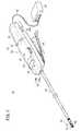
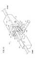
図1は、本発明の一実施形態に係る医療用マニピュレータ10を示す斜視図である。医療用マニピュレータ10は、先端に設けられたエンドエフェクタ12で針や糸あるいは生体の一部を把持し又は生体に触れて、所定の処置を行うための医療機器である。医療用マニピュレータ10は、先端に設けられるエンドエフェクタ12の種類に応じて、ニードルドライバ、把持鉗子、モノポーラ電気メス、バイポーラ電気メス等として構成され得る。 FIG. 1 is a perspective view showing a
以下では、先ず、ニードルドライバの実施形態とした医療用マニピュレータ10の構成を概略的に説明し、その後、各部の構成を詳細に説明する。 Below, first, the structure of the
医療用マニピュレータ10は、エンドエフェクタ12を含む先端動作部14と、エンドエフェクタ12を駆動するハンドル16と、エンドエフェクタ12とハンドル16とを連結するシャフト18とを備える。エンドエフェクタ12は、外科的処置を行う部分であり、図示例では、一対のグリッパ部材60、61を有し、所定の開閉動作軸を基準に開閉動作するグリッパ機構として構成されている。エンドエフェクタ12は、グリッパ機構に限らず、鋏や、電気メス用の電極として構成されてもよい。 The
エンドエフェクタ12を含む先端動作部14は、シャフト18に対して複数の自由度で姿勢変更が可能である。本実施形態では、先端動作部14は、シャフト18の軸線に対して左右に傾動する「傾動動作」(首振り動作)と、当該先端動作部14の長手方向の軸線を中心に回転する「ロール動作」とを行うことができる。傾動動作は、左右方向への首振りに代えて、シャフト18の軸線に対して上下に傾動する動作であってもよい。 The distal
シャフト18は、長尺で細径の管状部材であり、その中空部には、エンドエフェクタ12の開閉動作、先端動作部14のロール動作及び傾動動作をするのに必要な動力を、ハンドル16側から先端動作部14に伝達するための動力伝達機構を構成する複数の部材が挿通及び配置されている。 The
ハンドル16は、複数の操作部を含むハンドル本体20と、ハンドル本体20に着脱可能でありモータ38を含む駆動ユニット22とを備え、ハンドル本体20に駆動ユニット22が装着された状態でモータ38が駆動した際、モータ38の駆動力が先端動作部14に伝達されるように構成される。このため、この医療用マニピュレータ10は、ハンドル本体20、シャフト18及び先端動作部14を含むマニピュレータ本体については、所定回数使用した後に廃棄し、一方、駆動ユニット22については、接続するマニピュレータ本体を変えて何度も使用する、という利用形態を取ることができる。 The
本実施形態に係る医療用マニピュレータ10においては、ロール動作をモータ38による電動駆動とし、傾動動作を手動駆動としたが、これとは逆に、傾動動作をモータ38による電動駆動とし、ロール動作を手動駆動とする構成を採用してもよい。このように、傾動動作とロール動作の両方を電動駆動とするのではなく、いずれか一方だけを駆動源により動かす構成であるため、駆動源を一つにする分、両方を電動駆動とする構成と比較して、小型・軽量化を実現することができる。 In the
ハンドル本体20は、シャフト18の基端が連結された胴体部23と、胴体部23に設けられたレバー24(開閉操作部)、胴体部23に設けられた傾動用ホイール26(傾動操作部)と、胴体部23に設けられたロール用スイッチ28(ロール操作部)とを備える。 The
胴体部23は、医療用マニピュレータ10の使用時に使用者が握る部分であり、本実施形態では、シャフト18の軸線方向にやや長く延在するスティック状に構成されている。胴体部23は、上部カバー29aと下部カバー29bとからなる筐体29を有し、当該筐体29内に、プーリ、歯車、ワイヤ等の駆動部品が配置される。 The
胴体部23の下部には、エンドエフェクタ12の開閉操作を行うためのレバー24が、その先端側を支点として上下に揺動自在に設けられる。本実施形態では、レバー24は、手動用操作部として構成されており、レバー24に対する操作力が機械的に先端動作部14のエンドエフェクタ12に伝達されることで、エンドエフェクタ12の開閉動作が行われる。具体的には、レバー24を開いた状態でエンドエフェクタ12が開き、レバー24を閉じるとエンドエフェクタ12が閉じるように構成されている。 A
先端動作部14を傾動動作させるための傾動用ホイール26は、胴体部23の長手方向の中央付近に設けられる。当該傾動用ホイール26は、手動用操作部として構成されており、周方向の一部が筐体29から露出している。傾動用ホイール26を回転操作すると、その操作力が、ハンドル16及びシャフト18内に設けられた傾動動作用の動力伝達系を介して機械的に先端動作部14に伝達され、先端動作部14がシャフト18の軸線に対して非平行な方向(左右方向又は上下方向)に傾動する。 The
先端動作部14をロール動作させるためのロール用スイッチ28は、胴体部23の先端寄りの上部に設けられる。本実施形態では、ロール用スイッチ28は、コントローラ44を介してモータ38に対して操作指令を与える電動操作部として構成される。図15に示すように、ロール用スイッチ28は、スイッチ基盤30と、スイッチ基盤30上に設けられたタクトスイッチ31a、31bと、スイッチ基盤30に対して傾動可能なスイッチプレート32と、柔軟な材料(例えば樹脂等)により構成されたスイッチカバー33とを備える。 A
再び図1を参照する。ロール用スイッチ28を押圧操作すると、押圧した位置に応じた信号が、コネクタ54及びケーブル42を介してコントローラ44に送信され、当該コントローラ44の制御作用下にモータ38が駆動し、モータ38の駆動力が先端動作部14に伝達されることで、先端動作部14が当該先端動作部14の長手方向の軸線を中心として回転する。本実施形態では、ロール用スイッチ28の右寄りの部分を押すと先端動作部14が右回りに回転し、ロール用スイッチ28の左寄りの部分を押すと先端動作部14が左回りに回転する。 Refer to FIG. 1 again. When the
図2及び図3に示すように、駆動ユニット22は、ハウジング36と、ハウジング36内に配置されたモータ38(駆動原)と、モータ38の出力軸に固定された駆動歯車40(ピニオンギア)とを有し、ハンドル本体20の後部に着脱可能である。ハウジング36は、駆動ユニット22がハンドル本体20に装着(接続)された状態で、ハンドル本体20とともにハンドル16の筐体29を構成する部分であり、本実施形態では、ハンドル本体20の長手方向にやや長く延在する形状を有する。モータ38は、モータホルダによってハウジング36に固定される。モータ38の出力軸に固定された駆動歯車40は、ハウジング36の先端よりも先端側に突出する。 As shown in FIGS. 2 and 3, the
駆動ユニット22は、動力線及び信号線を含むケーブル42を介してコントローラ44に接続されている。コントローラ44は、モータ38への電力供給と駆動制御を行うものであり、外部電源から電力を受ける。ロール用スイッチ28を操作すると、その操作に応じた信号がコントローラ44に送信され、コントローラ44がモータ38の駆動を制御する。なお、コントローラ44の機能の一部又は全部は、駆動ユニット22に一体的に搭載され得る。 The
ハンドル本体20の胴体部23には、モータ38の出力軸に固定された駆動歯車40が通過可能な開口部23aが設けられ、駆動歯車40は、当該開口部23aを通して、胴体部23内に進入可能である。駆動ユニット22をハンドル本体20の胴体部23に装着すると、モータ38の出力軸38aに固定された駆動歯車40と、胴体部23内に設けられた従動歯車128とが噛み合う。この状態で、モータ38が回転すると、モータ38の回転駆動力が、駆動歯車40と従動歯車128を介してハンドル本体20側へと伝達される。 The
ハンドル本体20の胴体部23の後部両側には、当該ハンドル本体20の長手方向に沿って延在するハンドル側スライドガイド部34が設けられる。駆動ユニット22のハウジング36の前部両側には、当該ハウジング36の長手方向に沿って延在するユニット側スライドガイド部37が設けられる。駆動ユニット22をハンドル本体20に接続する際には、駆動ユニット22をハンドル本体20の胴体部23の後方から胴体部23に向かって移動させ、ユニット側スライドガイド部37とハンドル側スライドガイド部34とを係合させる。そして、これらのガイド部のガイド作用下に、駆動ユニット22をハンドル本体20に対して最大限度まで押し込むと、駆動歯車40と従動歯車128が噛み合う。 On both sides of the rear portion of the
図3に示すように、ハンドル本体20に駆動ユニット22を装着する際の、ハンドル本体20を基準とした駆動ユニット22の移動方向に関して、駆動歯車40の前側外周縁部は、前側に向かって縮径するテーパ形状に形成され、従動歯車128の後側外周縁部は、後側に向かって縮径するテーパ形状に形成される。 As shown in FIG. 3, when the
本実施形態では、ハンドル本体20に駆動ユニット22を装着する際の、ハンドル本体20を基準とした駆動ユニット22の移動方向は、ハンドル本体20の長手方向の前方であり、駆動歯車40の先端側外周縁部は、先端側に向かって縮径するテーパ形状に形成され、従動歯車128の基端側外周縁部は、基端側に向かって縮径するテーパ形状に形成される。この構成により、駆動ユニット22をハンドル本体20に装着する際に、駆動歯車40に形成されたテーパ形状と、従動歯車128に形成されたテーパ形状とによるガイド作用によって、駆動歯車40と従動歯車128との噛み合いがスムーズに行われるため、装着作業を迅速に行うことができる。 In the present embodiment, when the
図3に示すように、ハンドル本体20の胴体部23の後部には、ハンドル側コネクタ50が設けられ、駆動ユニット22の後部には、ユニット側コネクタ52が設けられる。ハンドル本体20に駆動ユニット22が装着された状態で、ハンドル側コネクタ50とユニット側コネクタ52とは相互に電気的に接続される。すなわち、ハンドル側コネクタ50とユニット側コネクタ52とにより、コネクタ54が構成される。ハンドル側コネクタ50とユニット側コネクタ52とが接続された状態で、ロール用スイッチ28を操作すると、当該ロール用スイッチ28の状態に対応した信号が、コネクタ54及びケーブル42の信号線を介してコントローラ44に伝送され、コントローラ44の制御作用下に、駆動ユニット22に搭載されたモータ38が駆動する。 As shown in FIG. 3, a handle-
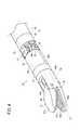
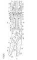
図4は、シャフト18の先端に連結された先端動作部14を示す斜視図である。図5は、先端動作部14の分解斜視図である。図6は、先端動作部14の縦断面図である。図4〜図6に示すように、先端動作部14は、開閉動作可能なエンドエフェクタ12と、エンドエフェクタ12が固定された中空円筒状の回転スリーブ56(先端側回転体)と、回転スリーブ56を軸線回りに回転可能に支持する先端側支点ブロック58とを有する。 FIG. 4 is a perspective view showing the distal
エンドエフェクタ12は、第1グリッパ部材60と、第2グリッパ部材61とからなる。第1グリッパ部材60と第2グリッパ部材61とは、ピン63により、グリッパ軸線Ogを中心として回転可能に連結される。第1グリッパ部材60の顎部60aには、滑り止め用の多数の凹凸が形成された把持面60bが設けられる。第2グリッパ部材61の顎部61aには、滑り止め用の多数の凹凸が形成された把持面61bが設けられる。第1グリッパ部材60の基部60cは、略円筒形状であり、当該基部60cに、第2グリッパ61の基部61cがピン63により回動可能に連結される。第1グリッパ部材60の把持面60bと、第2グリッパ部材61の把持面61bとにより、例えば針等の把持対象物が把持される。 The
第2グリッパ部材61の基部61cは、リンク部材62を介して、伝達部材64に連結される。当該基部61cとリンク部材62、及び、リンク部材62と伝達部材64は、それぞれピン65a、65bにより回転可能に連結される。伝達部材64は、ガイド管部64aと、ガイド管部64aの先端に設けられたフランジ64bと、フランジ64bの縁部から先端方向に互いに平行に延出する支持アーム64cとを有し、回転スリーブ56内に軸線方向に移動可能に配置される。支持アーム64cに設けられたピン孔64dに、ピン65bが嵌合される。 The base 61 c of the
伝達部材64と回転スリーブ56との間には圧縮スプリング66が配置される。圧縮スプリング66は、一端が伝達部材64のフランジ64bに当接し、他端が回転スリーブ56の内周部に設けられた段差部56a(図6参照)に当接し、伝達部材64を先端方向に弾性的に常時付勢する。 A
伝達部材64には、エンドカラー68が先端側から挿通される。エンドカラー68の先端部は、伝達部材64のガイド管部64aの先端面に当接して係合する係合膨出部68aとして構成される。エンドカラー68は、先端動作部14とシャフト18との間の関節部17(図4及び図6参照)に通されたプルワイヤ70の先端に固定される。 An
プルワイヤ70は、ハンドル16のレバー24に対する操作に応じてシャフト18内及び先端動作部14内を進退移動する部材であり、プルワイヤ70が基端方向に変位すると、当該プルワイヤ70に固定されたエンドカラー68により伝達部材64が基端方向に押圧され、これにより圧縮スプリング66の付勢力に抗して、伝達部材64が基端方向に変位する。この伝達部材64の基端方向への変位に伴い、リンク部材62に連結された第2グリッパ部材61が、第1グリッパ部材60に対して閉じる方向に回動させられる。図6では、第2グリッパ部材61の把持面61bと第1グリッパ部材60の把持面60bとが接触する位置まで閉じた状態の第1グリッパ部材60を仮想線で示している。 The
第2グリッパ部材61の把持面61bと第1グリッパ部材60の把持面60bとが接触する位置まで閉じた状態から、プルワイヤ70及びエンドカラー68が前進すると、圧縮スプリング66の弾発力により伝達部材64が前進するため、リンク部材62を介して第1グリッパ部材60が第2グリッパ部材61に対して開く方向に回動し、元の状態に復帰する。この動作が、エンドエフェクタ12の開閉動作である。 When the
なお、本実施形態において、エンドエフェクタ12は、第1グリッパ部材60が固定部として構成され、第2グリッパ部材61が可動部として構成されているが、両方のグリッパ部材60、61が可動部として構成されてもよい。 In the present embodiment, the
回転スリーブ56は、先端の縮径部56bにおいて、第1グリッパ部材60の基部60cに嵌合し固着されている。回転スリーブ56において、基端には傘歯車部56cが設けられ、この傘歯車部56cよりも先端側に環状凹部56dが設けられる。エンドエフェクタ12、回転スリーブ56、伝達部材64、エンドカラー68及び圧縮スプリング66は、先端動作部14の長手方向のロール軸線Orを中心として、先端側支点ブロック58に対して一体的に回転可能である。 The
先端側支点ブロック58は、半円状の上部ブロック71と、半円状の下部ブロック72とからなり、上部ブロック71と下部ブロック72とが組み合わされることにより中空円筒状となる。先端側支点ブロック58の外径は、3mm〜8mmであることが好ましく、本実施形態では、5mmとして説明する。先端側支点ブロック58の内径は、2mm〜7mmであることが好ましく、本実施形態では、4mmとして説明する。 The front end
上部ブロック71と下部ブロック72の内周部には、それぞれ円弧状突起71a、72aが設けられ、円弧状突起71a、72aと、回転スリーブ56に設けられた環状凹部56dとが係合することにより、回転スリーブ56が先端側支点ブロック58に対して回転可能且つ軸線方向に移動不可能に連結される。円弧状突起71a、72aは、長手方向の中心軸に向って所定の突出量(例えば、0.7mm)を有し、強度が得られるように長手方向に所定の幅(例えば、1mm)を有する。また、本実施形態では、半円状の上部ブロック71の内周部に円弧状突起71aが、半円状の下部ブロック72の内周部に円弧状突起72aがそれぞれ1つ設けられているが、これに限らず、円弧状突起71aは複数の突起から構成されていても良い。例えば、円弧状突起71aは上部ブロック71の内周部上に30°間隔で配置されていてもよく、この場合、円弧状突起71aは3つの円弧状突起から構成される。 Arc-shaped
先端側支点ブロック58とシャフト側支点ブロック59とは、関節ピン73、74により、傾動軸線Oyを中心に互いに回動可能に連結される。シャフト側支点ブロック59は、シャフト18の胴体部分を構成する中空状のシャフト本体19の先端に固定される。シャフト側支点ブロック59とシャフト本体19とにより、シャフト18が構成される。 The tip
本実施形態において、傾動軸線Oyは、上下方向に設定されているが、シャフト本体19の軸線に対して交差する他の方向に設定されてもよい。先端側支点ブロック58は、筒部58aと、筒部58aの基端の上部及び下部から互いに平行に基端方向に突出する舌片部58b、58cとを有する。シャフト側支点ブロック59は、筒部59aと、筒部59aの先端の上部及び下部から互いに平行に先端方向に突出する舌片部59b、59cとを有する。先端側支点ブロック58の舌片部58b、58cと、シャフト側支点ブロック59の舌片部59b、59cとに関節ピン73、74が嵌合される。 In the present embodiment, the tilt axis Oy is set in the vertical direction, but may be set in another direction that intersects the axis of the
図5〜図9に示すように、シャフト側支点ブロック59の筒部59aの先端には、支持ブロック76が装着される。支持ブロック76は、互いに平行に対向する上下の支持プレート77、78と、支持プレート77、78の左右両端後部を連結する連結部79とを有する。上側の支持プレート77には、上側の関節ピン73、74が挿入されるピン孔77aと、2つのピン84の上端がそれぞれ挿入される左右のピン孔77bとが設けられる。下側の支持プレート78には、従動プーリ90の縮径上端部90aが挿入される孔部78aと、2つのピン84の下端がそれぞれ挿入される左右のピン孔78bが設けられる。 As shown in FIGS. 5 to 9, a
図7〜図9に示すように、先端動作部14のシャフト18に対する傾動軸線Oyの近傍であって、プルワイヤ70(開閉駆動伝達部80)の、先端動作部14の傾動方向の両側(本実施形態では左右両側)に、プルワイヤ70をガイドするガイド部82が設けられる。このようなガイド部82が設けられるため、先端動作部14がシャフト18に対して屈曲した際に、ガイド部82によってプルワイヤ70が支持されることにより、開閉駆動伝達部80の屈曲部が、先端動作部14の傾動支点の近傍に保持される。このため、先端動作部14がシャフト18に対して屈曲(傾斜)した際(図8参照)に、先端動作部14内でプルワイヤ70の先端が前進することを抑制又は防止できる。よって、エンドエフェクタ12で対象物を把持した状態を好適に維持できる。 As shown in FIGS. 7 to 9, the pull wire 70 (opening / closing drive transmission unit 80) is in the vicinity of the tilting axis Oy with respect to the
本実施形態では、ガイド部82として2つのガイドローラ83が、上下の支持プレート77、78の間に左右方向に並べて配置される。ガイドローラ83は、互いに平行に配置された2つのピン84により左右方向に間隔をおいて回転可能に支持される。2つのガイドローラ83の間には、上述したプルワイヤ70が通される。この構成により、先端動作部14がシャフト18に対して屈曲した状態で開閉駆動伝達部80を進退動作させたときでも、プルワイヤ70(開閉駆動伝達部80)の進退動作に伴ってガイドローラ83が回転するため、プルワイヤ70をスムーズに進退動作させることができる。従って、エンドエフェクタ12を確実に開閉動作させることができ、操作性に優れる。 In the present embodiment, two
図6に示すように、先端動作部14とシャフト18との間の関節部17は、傾動軸線Oy上に配置された一対の関節ピン73、74を有し、開閉駆動伝達部80の一部であるプルワイヤ70は、一対の関節ピン73、74間に設けられた隙間を、関節ピン73、74の軸線方向と交差する方向に進退移動可能である。この構成によれば、関節部17内におけるプルワイヤ70の配置スペースを容易に確保することができる。 As shown in FIG. 6, the
上側の支持プレート77と舌片部58bとの間には、傘歯車86(中間部材)が関節ピン73によって回転自在に支持される。傘歯車86は、支持プレート77及び舌片部58bとは独立に回転可能である。傘歯車86の歯部86aは、回転スリーブ56の基端に設けられた傘歯車部56cと、歯車部材88の先端に設けられた傘歯車部88aとに噛み合う。傘歯車部88aが設けられた歯車部材88は、中空円筒型の部材であり、その中空部内にプルワイヤ70が挿通される。 A bevel gear 86 (intermediate member) is rotatably supported by the
歯車部材88が回転する際、歯車部材88の回転力は、傘歯車86と傘歯車部86cを介して回転スリーブ56に伝達され、回転スリーブ56及びこれに固定されたエンドエフェクタ12が先端側支点ブロック58に対してロール軸線Orを中心に回転する。この動作が、先端動作部14のロール動作である。 When the
下側の支持プレート78と舌片部58cとの間には、従動プーリ90が関節ピン74によって回転自在に支持される。従動プーリ90は、先端側支点ブロック58の舌片部58cの内面に固着される。従って、従動プーリ90と、舌片部58cを含む先端側支点ブロック58とは、一体的にシャフト側支点ブロック59に対して揺動可能である。従動プーリ90には、傾動動作用のワイヤ150が巻き掛けられる。このワイヤ150は、一部が従動プーリ90に固定され、シャフト18内を介してハンドル16側まで配設される。ワイヤ150の配設構造の詳細については後述する。 A driven
ワイヤ150によって従動プーリ90が回転駆動されると、当該従動プーリ90に固定された先端側支点ブロック58が従動プーリ90と一体的に回転する。これにより、先端側支点ブロック58、回転スリーブ56及びエンドエフェクタ12を含む先端動作部14が、シャフト18に対して傾動軸線Oyを中心として回動する。この動作が、先端動作部14の傾動動作である。図8に、先端動作部14がシャフト18に対して傾斜した(屈曲した)状態を示す。先端動作部14の傾動動作は、先端動作部14がシャフト18に対して真直ぐの状態を中立位置(基準位置)として、プラス側(右側)とマイナス側(左側)にそれぞれ可動範囲を有する。本実施形態では、先端動作部14は、傾動動作に関して+70°〜−70°の可動範囲を有する。 When the driven
図10は、プルワイヤ70とプルロッド91との連結構造92を示す縦断面図である。図10に示すように、プルワイヤ70とプルロッド91とは、歯車部材88の基端に連結された中空シャフト89内で相対回転可能であり、且つプルロッド91の基端方向への引っ張り力がプルワイヤ70に伝達されるように連結されている。具体的には、プルワイヤ70の基端にはワイヤカラー93が固着され、プルロッド91の先端には中空状の外側カラー94が固着され、外側カラー94内にワイヤカラー93が配置される。ワイヤカラー93は、外側カラー94内で軸線回りに回転可能であるが、外側カラー94の先端に設けられた縮径部94aに引っかかることにより、外側カラー94から抜け出ないようになっている。 FIG. 10 is a longitudinal sectional view showing a
このように構成されるため、プルロッド91が軸線方向に変位した際には、連結構造92を介してプルロッド91に連結されたプルワイヤ70も軸線方向に変位することにより、エンドエフェクタ12の開閉動作が行われる。また、先端動作部14がロール動作する際には、プルワイヤ70がプルロッド91に対して回転することができるため、先端動作部14のロール動作に支障がないとともに、プルワイヤ70に捩じれ等が発生することがなく、プルワイヤ70の損傷を防止できる。 With this configuration, when the
図3に示すように、プルロッド91は、中空シャフト89内に挿通され、且つその基端が中空シャフト89の基端から突出する。一方、レバー24は、その先端部において、胴体部23の先端寄りの箇所で胴体部23に対して揺動可能に連結される。レバー24の先端部近傍には、レバーロッド96の先端が回動可能に連結されており、当該レバーロッド96は、胴体部23の下方に、胴体部23の長手方向と略平行に配置される。胴体部23の下部には、後述するフック部材118を支持するフックホルダ116が固定され、当該フックホルダ116の先端面と、レバーロッド96の先端拡径部96aとの間に、圧縮スプリング98が配置される。この圧縮スプリング98は、レバーロッド96を先端方向に弾性的に常時付勢する。従って、レバーロッド96に連結されたレバー24は、圧縮スプリング98の弾発力により、常時、胴体部23に対して開く方向の力を受ける。 As shown in FIG. 3, the
図11は、弾性部材105を介してレバー24からの駆動力を開閉駆動伝達部80へと伝達する荷重制御機構100の斜視図である。図12A〜12Cは、荷重制御機構100及びその周辺部位の縦断面図である。荷重制御機構100は、プルワイヤ70とプルロッド91とからなる開閉駆動伝達部80と、操作部としてのレバー24との間の駆動力伝達経路上に設けられる。 FIG. 11 is a perspective view of the
本実施形態では、荷重制御機構100は、プルロッド91及びレバーロッド96の基端に設けられており、プルロッド91に固定された係止部102と、プルロッド91にガイドされて軸線方向に変位可能な可動部104と、レバーロッド96に固定され且つ可動部104に係合した支持連結体106と、可動部104よりも基端側でプルロッド91に対して位置決めされた固定部108と、可動部104と固定部108との間に配置された弾性部材105と、プルロッド91に螺合し且つ回転によってプルロッド91に対する軸線方向の位置が変位する調整ナット110(調整用部材)とを有する。 In the present embodiment, the
係止部102は、プルロッド91に対して軸線方向に変位不可能に固定され、弾性部材105によって先端方向に付勢された可動部104が係止部102に当接することで、可動部104がそれ以上先端側に変位しないように係止するストッパとして機能する。可動部104は、中空筒状に形成され、その中空部にプルロッド91が挿通される。可動部104は、弾性部材105により先端方向に弾性的に常時付勢される。 The locking
支持連結体106の下端部は、レバーロッド96の基端に螺合によって固定される。支持連結体106の上部側には左右のアーム107が設けられ、当該左右のアーム107間に固定部108が配置される状態で、支持連結体106の上端部がピン109を介して固定部108に回動可能に連結される。本実施形態において、弾性部材105は、可動部104と固定部108との間でプルロッド91の外側に配置されたコイル状の圧縮スプリング105Aである。レバーロッド96とともに可動部104が基端方向に変位することに伴って、プルロッド91が基端方向に変位するように、圧縮スプリング105Aの弾発力は、先端動作部14内に配置された圧縮スプリング66(図6参照)の弾発力よりも大きい。 The lower end portion of the
固定部108は、中空筒状に形成され、その基端には半径方向外方に膨出するフランジ108aが設けられる。圧縮スプリング105Aの一端は、可動部104に設けられた段差部分104aに当接し、圧縮スプリング105Aの他端は、フランジの前面に当接する。これにより、圧縮スプリング105Aは、可動部104と固定部108との間に保持される。固定部108は、調整ナット110の端面に当接することで係止され、これによりプルロッド91に対して位置決めされる。 The fixing
調整ナット110を回転させると調整ナット110のプルロッド91に対する軸方向位置が変位する。従って、調整ナット110により固定部108のプルロッド91に対する位置を調整し、且つ位置決めすることができる。 When the
上記のように構成された荷重制御機構100は、以下のように作用する。ハンドル本体20において、胴体部23に対してレバー24が開いた状態(図3参照)では、レバーロッド96、支持連結体106及び可動部104は、図12Aに示す位置にある。これを初期位置とする。この初期位置では、エンドエフェクタ12が全開状態となる位置までプルロッド91が前進している。使用者がレバー24を握り、レバー24を胴体部23側に引き寄せる(レバー24を閉じる)と、図12Bに示すように、レバーロッド96、支持連結体106及び可動部104が基端方向へ変位する。このとき、圧縮スプリング105A、可動部104及び調整ナット110を介してプルロッド91が基端方向に引っ張られるため、エンドエフェクタ12が閉じる方向に動作する。 The
エンドエフェクタ12が対象物をちょうど把持した位置から、さらにレバー24を胴体部23側に引き寄せると、図12Cに示すように、圧縮スプリング105Aが可動部104と固定部108との間で圧縮されることで、プルロッド91、固定部108及び調整ナット110の位置が保持されたまま、可動部104が固定部108側すなわち基端側へ変位する。このとき、固定部108と可動部104との距離は、図12Aの状態よりも短くなっている。このような荷重制御機構100の作用により、エンドエフェクタ12で対象物を把持した後、エンドエフェクタ12を閉じる方向にさらにレバー24を操作しても、圧縮スプリング105Aが圧縮変形することで、開閉駆動伝達部80へ過大な引っ張り荷重がかかることが防止される(過負荷防止機能)。 When the
また、荷重制御機構100によれば、エンドエフェクタ12で対象物を把持した状態で先端動作部14をシャフト18に対して屈曲させた際に、開閉駆動伝達部80とレバー24との間の駆動力伝達経路上に設けられた弾性部材105が伸長することにより、先端動作部14とシャフト18との間の関節部17でのプルワイヤ70の屈曲方向へのずれを補償する分だけ、プルワイヤ70が基端方向に変位させられる。このため、先端動作部14の屈曲に伴ってエンドエフェクタ12が開くことがない。すなわち、エンドエフェクタ12が対象物を把持した状態を確実に維持することができる(把持維持機能)。 Further, according to the
さらに、本実施形態の場合、コイル状の圧縮スプリング105Aが開閉駆動伝達部80の一部であるプルロッド91の外側を囲んで配置されるとともに固定部108がプルロッド91をガイドとして軸線方向に変位することから、固定部108の変位がスムーズに行われるため、上述した把持維持機能と過負荷防止機能を確実に発揮することができる。 Further, in the case of the present embodiment, the coil-shaped
本実施形態の場合、開閉駆動伝達部80を構成するプルロッド91に対する調整ナット110の位置を変えることにより、荷重制御機構100における弾性部材105の付勢力の大きさを容易に調整することができる。 In the case of this embodiment, the magnitude of the urging force of the
図3及び図13に示すように、本実施形態に係る医療用マニピュレータ10には、レバー24を胴体部23に対して所定位置でロックし、且つレバー24に対するロックを解除することができるロック機構114が設けられる。具体的には、ロック機構114は、エンドエフェクタ12が閉じる位置にレバー24が来たとき、胴体部23に対するレバー24の位置(姿勢)を保持するように構成される。 As shown in FIGS. 3 and 13, the
図13に示すように、本実施形態において、ロック機構114は、ハンドル本体20の胴体部23の下部に固定されたフックホルダ116と、フックホルダ116に回動可能に支持されたフック部材118と、フック部材118をレバー24側に付勢する弾性部材120と、フック部材118が所定位置まで回動したときにフック部材118に係合してフック部材118を保持する保持部122とを有する。フックホルダ116には、胴体部23の長手方向に沿った貫通孔116aが形成され、当該貫通孔116aにレバーロッド96が前後に変位可能に挿通される。 As shown in FIG. 13, in the present embodiment, the
フック部材118は、フックホルダ116の基端側で軸部119によって回動可能に支持された部材であり、レバー24が所定位置(以下、「第1の位置」という)に来たときレバー24に設けられた係合ピン25に係合可能である。フック部材118は、軸部119を含む基部118aと、基部118aの基端側から下方に延出するフック118bと、基部118aの基端側から上方に延出する左右の係合部118cとを有する。 The
弾性部材120は、本実施形態では、トーションスプリング120Aの形態で構成され、一端がフックホルダ116の基端側に設けられた凹部116bに係合し、他端がフック部材118に設けられた横溝部118eに係合した状態で、フック部材118をレバー24側(下方)に常時弾性的に付勢する。フックホルダ116に設けられた凹部116bの底部と、フック部材118の基部118aの下面とが当接することで、フック部材118がそれ以上、下向きに回動することが規制されている。 In this embodiment, the
保持部122は、胴体部23に固定されたベースプレート122aと、ベースプレート122aの左右両端から下方に延出する左右のアーム122bとを有する。各アーム122bには、内側に凸形状となる係合凸部122cが設けられる。フック部材118が第1の位置よりも胴体部23に近い第2の位置(フック部材118が保持部のアーム部に上下方向に重なる位置)まで回動した際、係合凸部122cと、フック部材118の係合部118cの外面に設けられた係合凹部118dとが係合することにより、フック部材118が保持部122に保持される。フック部材118が保持部122に保持された状態で、レバー24はフック部材118から離脱可能である。 The holding
ロック機構114は、さらに、フック部材118が保持部122に保持された状態でレバー24が胴体部23から離間する方向に変位した際、レバー24の動作に連動して変位し、フック部材118に当接することで保持部からフック部材118を離脱させる解除部124を有する。本実施形態において、解除部124は、フック部材118よりも後方で、レバーロッド96に固定され、レバーロッド96が前後方向に変位した際には、レバーロッド96と一体的に前後方向に移動する。解除部124の先端側には、フック部材118が保持部122に保持された状態でレバー24が胴体部23から離間する方向に変位した際にフック部材118に突き当たる突当部126が設けられる。 Further, when the
上記のように構成されたロック機構114は、以下のように作用する。図14Aにおいて、レバー24は胴体部23に対して最も下がった(開いた)位置にあり、フック部材118は最も下がった位置にあり、解除部124は最も後退した位置にある。図14Aの状態から、レバー24を胴体部23側に引き寄せていくと、レバー24に設けられた係合ピン25がフック部材118のフック118bの顎部118fを押すことで、フック部材118がトーションスプリング120Aの弾発力に抗して胴体部23側(上方)に回動する。そして、図14Bに示すように、係合ピン25が顎部118fを乗り越えると、係合ピン25がフック118bに係合するに至る。レバー24は、圧縮スプリング98によって、胴体部23に対して開く方向に弾性的に付勢されているが、係合ピン25がフック118bに係合した状態では、レバー24が開く方向に移動することができない。従って、使用者がレバー24から手を放しても、胴体部23に対するレバー24の位置は保持される。すなわち、レバー24に対するロックがなされる。 The
このように、エンドエフェクタ12により対象物を把持した状態でレバー24の位置をロックすることで、使用者がレバー24から手を放した状態でもエンドエフェクタ12による対象物の把持を維持することができる。よって、使用者の操作負荷を軽減することができる。 Thus, by locking the position of the
図14Cに示すように、さらにレバー24を閉じる方向に引き寄せると、係合ピン25によってフック部材118が押し上げられることで、フック部材118の係合部118cと保持部122とが係合する。係合部118cと保持部122との係合力は、トーションスプリング120Aの弾発力よりも大きいため、トーションスプリング120Aによってフック部材118が押し下げられることはない。フック部材118が保持部122に保持された状態で、レバー24の係合ピン25はフック部材118から離脱可能である。従って、使用者がレバー24から手を放すと、レバー24が下がり、レバー24を再び元の位置(図14A参照)に戻すことができる。 As shown in FIG. 14C, when the
このように、レバー24がロックされた状態から、レバー24を胴体部23にさらに近づける操作をするだけで、フック部材118とレバー24との係合を解除することができるため、レバー24に対するロックを迅速且つ簡単に解除することができる。 As described above, since the engagement between the
レバー24の係合ピン25とフック部材118との係合が解除された後、レバー24を下げる過程で、レバーロッド96及び解除部124は前進する。そして、図14Dに示すように、解除部124の突当部126がフック部材118に当接し、フック部材118を前方に押すと、それによってフック部材118が下方に回動させられることで、保持部122とフック部材118との係合が解除される。その結果、フック部材118は、トーションスプリング120Aによる付勢作用下に、図14Aに示す初期位置に復帰する。 After the engagement between the
このように、レバー24とフック部材118との係合が解除された後、レバー24を胴体部23から離す方向に動かすだけで、保持部122とフック部材118との係合が自動的に解除され、フック部材118を初期位置に迅速に戻すことができる。よって、フック部材118を初期位置に戻す操作を行う必要がなく、操作性に優れる。 As described above, after the engagement between the
次に、主として図3及び図6を参照し、先端動作部14のロール動作に関連する機構を説明する。本実施形態において、先端動作部14のロール動作は、モータ38の駆動力が先端動作部14に伝達されることにより行われる。先端動作部14をロール動作させるためのロール動作駆動系は、上述したモータ38と、モータ38に固定された駆動歯車40と、駆動歯車40に噛み合う従動歯車128と、従動歯車128が固定されたロール駆動伝達管130と、ロール駆動伝達管130の先端と噛み合う傘歯車86と、傘歯車86と噛み合う回転スリーブ56とを備える。本実施形態において、歯車部材と中空シャフト89とにより、ロール駆動伝達管130が構成される。また、ロール駆動伝達管130(図3及び図7も参照)と、傘歯車86と、回転スリーブ56とにより、ハンドル16側から先端動作部14側に回転駆動力を伝達する回転駆動伝達部132が構成される。 Next, a mechanism related to the roll operation of the distal
駆動ユニット22がハンドル本体20に装着され、且つコントローラ44が電源に接続された状態で、図3等に示すロール用スイッチ28を押圧操作すると、モータ38が回転し、その駆動力が、駆動歯車40、従動歯車128、ロール駆動伝達管130、傘歯車86及び回転スリーブ56を介して、先端動作部14に伝達される。これにより、先端動作部14のロール動作が行われる。 When the
本実施形態に係る医療用マニピュレータ10によれば、ハンドル16側から先端動作部14側への回転力の伝達を、ワイヤとプーリを介して行うのではなく、ロール駆動伝達管130等を介して行うため、先端動作部14を無制限の回転範囲でロール動作させることができる。また、開閉駆動伝達部80(プルワイヤ70及びプルロッド91)は、ロール駆動伝達管130の内側に挿通配置されるためロール駆動伝達管130の回転の影響を受けることなくエンドエフェクタ12に開閉駆動力を適切に伝達できる。 According to the
さらに、図6に示すように、開閉駆動伝達部80は、関節部17に対応する部分(プルワイヤ70)が可撓性を有するため、簡単な構成で、エンドエフェクタ12に開閉駆動力を適切に伝達できる。従って、医療用マニピュレータ10によれば、先端動作部14の機構を複雑化することなく、先端動作部14の開閉動作と傾動動作を可能な構造を維持しつつ、回転範囲が無制限のロール動作を実現できる。 Further, as shown in FIG. 6, the opening / closing
次に、先端動作部14の傾動動作に関連する機構を説明する。図15は、ハンドル16の斜視図である。なお、図15では、構造の理解を容易にするため、上部カバー29a及び傾動用ホイール26を仮想線で示している。ハンドル本体20の胴体部23は、筐体29内に収容されたハンドル16フレームを有する。当該ハンドル16フレームは、第1フレーム134、第2フレーム136及び第3フレーム138を有する。 Next, a mechanism related to the tilting operation of the distal
第1フレーム134は、胴体部23の先端側に設けられ、その上部にはロール用スイッチ28が取り付けられる。第2フレーム136は第1フレーム134の後方に隣接して配置される。第3フレーム138は、第2フレーム136の後方に隣接して配置される。 The
傾動用ホイール26には、第1駆動軸140が固定されており、傾動用ホイール26と第1駆動軸140とは一体的に回転する。第1駆動軸140は、上下方向の軸線を中心に上部カバーに回転可能に支持され、第1歯車141を有する。第1歯車141は、第2駆動軸142に設けられた第2歯車143に噛み合う。第2駆動軸142は、第2フレーム136に、第1駆動軸140と平行に配置され、第2歯車143とウォームギア144とを同軸上に有する。第2歯車143とウォームギア144とは一体的に回転する。第2フレーム136には、ウォームギア144と噛み合うウォームホイール147を有する回転体146が、胴体部23の左右方向の軸線を中心に回転可能に配置される。 The
図16は、ハンドル16側におけるワイヤの配設構造を示す斜視図(一部断面図)である。図17は、ハンドル16側におけるワイヤの配設構造を示す模式図である。 FIG. 16 is a perspective view (partially sectional view) showing a wire arrangement structure on the
回転体146には、ウォームホイール147と駆動プーリ148とを同軸上に有する。ウォームホイール147と駆動プーリ148とは一体的に回転する。駆動プーリ148には、ワイヤ150が巻き掛けられ、当該ワイヤ150は、シャフト18内に挿通され、シャフト18の先端側で従動プーリ90(図6等参照)に巻き掛けられる。 The
ハンドル本体20において、駆動プーリ148の先端側(前方)には、第1中間プーリ152と第2中間プーリ154とが配置され、当該第1中間プーリ152と第2中間プーリ154とにワイヤ150が巻き掛けられる。第1中間プーリ152と第2中間プーリ154は、上下方向の軸線を中心として、それぞれピン155、156によって第1フレーム134に回転可能に支持される。第1フレーム134には、第1中間プーリ152と第2中間プーリ154とを配置するための、基端方向に開放した形状の配置溝134a、134bが、上下に並んで設けられる。 In the
本実施形態において、ハンドル16には、駆動プーリ148と従動プーリ90との間のワイヤ150の一方側部分に張力を付与する第1テンション機構158と、駆動プーリ148と従動プーリ90との間のワイヤ150の他方側部分に張力を付与する第2テンション機構164とが設けられる。第1テンション機構158は、ワイヤ150に巻き掛けられた第1テンション用プーリ159と、第1テンション用プーリ159を支持し且つ変位可能に設けられた第1保持部160と、第1保持部160の位置を調整し位置決めする第1調節部161とを備える。同様に、第2テンション機構164は、ワイヤ150に巻き掛けられた第2テンション用プーリ165と、第2テンション用プーリ165を支持し且つ変位可能に設けられた第2保持部166と、第2保持部166の位置を調整し位置決めする第2調節部167とを備える。 In the present embodiment, the
ハンドル本体20において、第1テンション用プーリ159と第2テンション用プーリ165とは、駆動プーリ148の基端側(後方)に配置される。第1テンション用プーリ159と第2テンション用プーリ165は、左右方向の軸線を中心として回転可能に支持される。具体的には、第1テンション用プーリ159が、支持軸170によって第1保持部160の先端部に回転可能に支持されるとともに、支持軸170が、第2フレーム136の側壁に設けられた前後方向に延在する長孔171に前後方向に摺動可能にガイドされる。同様に、第2テンション用プーリ165が、支持軸172によって第2保持部166の先端部に回転可能に支持されるとともに、支持軸172が、第2フレーム136の側壁136aに設けられた前後方向に延在する長孔173に前後方向に摺動可能にガイドされる。 In the
図17に示すように、第1保持部160には、ネジ孔160aが設けられ、当該ネジ孔160aに、第1調節部161のネジ棒161aが螺合する。第1調節部161の頭部161bは、ネジ棒161aよりも大径である。第1調節部161のネジ棒161aは、第2フレーム136の後部壁136bに設けられた貫通孔に後方から挿通され、当該後部壁136bに頭部161bが当接する。第1調節部161を回転させると、螺合作用によって第1保持部160が前後方向に移動する。従って、第1保持部160に支持された第1テンション用プーリ159の位置を調整することで、駆動プーリ148と従動プーリ90との間のワイヤ150の一方側部分に付与する張力を調整することができる。 As shown in FIG. 17, the
第2保持部166には、ネジ孔166aが設けられ、当該ネジ孔166aに、第2調節部167のネジ棒167aが螺合する。第2調節部167の頭部167bは、ネジ棒167aよりも大径である。第2調節部167のネジ棒167aは、第2フレーム136の後部壁136bに設けられた貫通孔に後方から挿通され、当該後部壁136bに頭部167bが当接する。第2調節部167を回転させると、螺合作用によって第2保持部166が前後方向に移動する。従って、第2保持部166に支持された第2テンション用プーリ165の位置を調整することで、駆動プーリ148と従動プーリ90との間のワイヤ150の他方側部分に付与する張力を調整することができる。 The
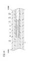
図18は、図16におけるXVIII−XVIII線に沿った横断面図である。図18に示すように、シャフト18とロール駆動伝達管130との間には、シャフト18の軸線に沿って延在する環状空間21が設けられ、ワイヤ150は、当該環状空間21に挿通される。上述したように、ワイヤ150は、シャフト18の先端に配置された従動プーリ90(図6参照)に巻き掛けられる。 18 is a cross-sectional view taken along line XVIII-XVIII in FIG. As shown in FIG. 18, an
図5に示すように、シャフト本体19の先端内周面における周方向の異なる位置に、ワイヤ150をガイドする2つのガイド溝19aが設けられる。また、シャフト本体19の先端に固定されるシャフト側支点ブロック59には、周方向の異なる位置に、ワイヤ150が摺動可能に挿通される2つのガイド孔59dが設けられる。各ガイド孔59dは、シャフト側支点ブロック59の筒部59aを軸線方向に貫通する。図9に示すように、ワイヤ150は、2つのガイド孔59dから引き出された部分で、従動プーリ90に巻き掛けられる。 As shown in FIG. 5, two guide grooves 19 a that guide the
次に、上記のように構成された傾動動作に関連する機構の作用について説明する。図15に示す傾動用ホイール26を手動により回転操作すると、その操作力が、第1駆動軸140、第2駆動軸142、回転体146に伝達される。回転体146に伝達された回転力は、回転体146に設けられた駆動プーリ148に巻き掛けられたワイヤ150を駆動する。この場合、駆動プーリ148との従動プーリ90との間のワイヤ150の一方側部分が、第1中間プーリ152と第1テンション用プーリ159とに巻き掛けられ、駆動プーリ148との従動プーリ90との間のワイヤ150の他方側部分が、第2中間プーリ154と第2テンション用プーリ165とに巻き掛けられ、張力を付与された状態で、駆動プーリ148の回転に応じて駆動される。ワイヤ150の駆動は、シャフト18の先端で、従動プーリ90の回転となって出力され、これにより、先端動作部14のシャフト18に対する傾動動作が行われる。 Next, the operation of the mechanism related to the tilting operation configured as described above will be described. When the
本実施形態に係る医療用マニピュレータ10は、第1テンション機構158及び第2テンション機構164を備えることにより、駆動プーリ148と従動プーリ90間のワイヤ150の一方側と他方側について、個別にワイヤ150に対して張力を付与し、ワイヤ150全体に適切な張力を付与することができる。これにより、使用者の操作に対して、先端動作部14が正確に応答し、優れた操作性が得られる。 The
また、第1テンション機構158と第2テンション機構164の各々が、テンション用プーリ159、165と、保持部160、166と、調節部161、167とを備えるため、駆動プーリ148と従動プーリ90間のワイヤ150の一方側と他方側について、個別にワイヤ150の張力を調整できる。よって、駆動プーリ148から従動プーリ90へのワイヤ150を介した動力伝達をより適切に行うことができる。 Further, each of the
さらに、本実施形態に係る医療用マニピュレータ10では、2つのテンション用プーリ159、165と2つの中間プーリ152、154が駆動プーリ148を基準としてその前後に配置されるため、ハンドル16内でワイヤ150が効率的に配設され、その結果、ハンドル16を小さく構成することができる。 Further, in the
医療用マニピュレータ10では、ハンドル16には、先端動作部14の傾動動作とロール動作のうち一方の動作に対する手動操作を行うための手動用操作部と、傾動動作とロール動作のうち他方の動作を指示するための電動用操作部と、電動用操作部に対する操作に基づき動作する駆動源とが設けられ、手動用操作部に対する使用者の操作力は、第1動力伝達経路を介して、機械的に先端動作部14に伝達され、駆動源の駆動力は、第2動力伝達経路を介して、先端動作部14に伝達され、第1動力伝達経路の途中には、手動用操作部側から先端動作部14側への動力を伝達するが、その逆方向へは動力を伝達しないように構成された一方向動力伝達機構176が設けられる。 In the
本実施形態では、傾動用ホイール26が、上記の手動用操作部に相当し、ロール用スイッチ28が、上記の電動用操作部に相当し、モータ38が、上記の駆動源に相当し、傾動用ホイール26と先端動作部14との間の動力伝達経路(第2駆動軸142、回転体146、ワイヤ150等)が、上記の第1動力伝達経路に相当し、モータ38と先端動作部14との間の動力伝達経路(ロール駆動伝達管130等)が、上記の第2動力伝達経路に相当する。 In the present embodiment, the
なお、本実施形態と異なり、傾動動作が電動駆動により行われ、ロール動作が手動駆動により行われる構成が採用される場合、ロール用の手動用操作部と先端動作部14との間の動力伝達経路が、上記の第1動力伝達経路に相当し、傾動用の電動操作部に基づいて動作する駆動源と先端動作部14との間の動力伝達経路が、上記の第2動力伝達経路に相当する。 Unlike the present embodiment, when a configuration is employed in which the tilting operation is performed by electric drive and the roll operation is performed by manual driving, power transmission between the manual operation unit for roll and the
図17に示すように、本実施形態では、一方向動力伝達機構176は、上述したウォームギア144とウォームホイール147とにより構成される。第1動力伝達経路において、ウォームホイール147は、ウォームギア144よりも先端動作部14側に配置される。 As shown in FIG. 17, in the present embodiment, the one-way
一方向動力伝達機構176を備えた医療用マニピュレータ10では、ロール用スイッチ28に基づいて先端動作部14を動作させる際に、先端動作部14は機構上の干渉によって傾動動作方向の力を受けるが、一方向動力伝達機構176により先端動作部14側から傾動用ホイール26側への動力の伝達が遮断される。このため、ロール用スイッチ28に基づいて先端動作部14を動作させる際に、使用者が手で傾動用ホイール26を固定しなくても、先端動作部14が干渉動作することがなく、操作性に優れる。 In the
医療用マニピュレータ10では、ロール動作だけを電動駆動とし、傾動動作については手動駆動とする構成を採用することにより、小型・軽量化を実現している。仮に、ロール動作と傾動動作の両方を電動駆動とした場合には、大きなギヤ比(ギヤードモータ)又はモータ制御により上述した干渉動作を防止できるが、ロール動作と傾動動作のうち一方を手動駆動とし他方を電動駆動とした構成の場合には、大きなギヤ比(ギヤードモータ)又はモータ制御を利用した干渉動作防止手段は採り得ない。 The
これに対し、医療用マニピュレータ10は、モータ38の搭載個数を1つとしたことによる小型・軽量化に加え、上述した一方向動力伝達機構176を備えることにより、上述した干渉動作の防止も実現できる。 On the other hand, the
上記において、本発明について好適な実施の形態を挙げて説明したが、本発明は前記実施の形態に限定されるものではなく、本発明の要旨を逸脱しない範囲において、種々の改変が可能なことは言うまでもない。 In the above description, the present invention has been described with reference to preferred embodiments. However, the present invention is not limited to the above-described embodiments, and various modifications can be made without departing from the scope of the present invention. Needless to say.
10…医療用マニピュレータ 12…エンドエフェクタ
14…先端動作部 16…ハンドル
18…シャフト 19…シャフト本体
20…ハンドル本体 22…駆動ユニット
23…胴体部 24…レバー
26…傾動用ホイール 28…ロール用スイッチ
38…モータ 40…駆動歯車
56…回転スリーブ 70…プルワイヤ
73、74…関節ピン 80…開閉駆動伝達部
82…ガイド部 83…ガイドローラ
86…傘歯車 88…歯車部材
90…従動プーリ 91…プルロッド
96…レバーロッド 98…圧縮スプリング
100…荷重制御機構 104…可動部
105、120…弾性部材 108…固定部
110…調整ナット 114…ロック機構
118…フック部材 122…保持部
124…解除部 128…従動歯車
130…ロール駆動伝達管 144…ウォームギア
147…ウォームホイール 148…駆動プーリ
150…ワイヤ 152…第1中間プーリ
154…第2中間プーリ 158…第1テンション機構
159…第1テンション用プーリ 160…第1保持部
161…第1調節部 164…第2テンション機構
165…第2テンション用プーリ 166…第2保持部
167…第2調節部 176…一方向動力伝達機構DESCRIPTION OF
Claims (4)
Translated fromJapanese前記ハンドルから延出したシャフトと、
開閉動作が可能なエンドエフェクタを有し、前記シャフトに対して傾動動作が可能に連結され、且つロール動作が可能な先端動作部と、
前記ハンドル側から前記先端動作部へ前記開閉動作のための駆動力を伝達する開閉駆動伝達部と、
前記ハンドルから前記先端動作部へ前記ロール動作のための回転力を伝達する回転駆動伝達部と、を備え、
前記回転駆動伝達部は、前記シャフトの延在方向に沿って延在し且つ前記シャフト内に回転可能に配置されたロール駆動伝達管と、前記シャフトと前記先端動作部との間の関節部に設けられ前記ロール駆動伝達管と噛み合い且つ前記先端動作部の傾動支点を中心に回転可能な中間部材と、前記先端動作部に設けられ前記中間部材と噛み合い且つロール軸線を中心に回転可能な先端側回転体とを有し、
前記開閉駆動伝達部は、前記ロール駆動伝達管の内側に配置され、少なくとも前記関節部に挿通された部分が可撓性を有する、
ことを特徴とする医療用マニピュレータ。A handle,
A shaft extending from the handle;
An end effector capable of opening and closing, a tip operating unit connected to the shaft so as to be tiltable and capable of rolling;
An opening / closing drive transmission unit for transmitting a driving force for the opening / closing operation from the handle side to the tip operation unit;
A rotational drive transmission unit configured to transmit a rotational force for the roll operation from the handle to the tip operation unit,
The rotational drive transmission unit extends along the extending direction of the shaft and is provided at a joint portion between the roll drive transmission tube disposed rotatably in the shaft and the shaft and the distal end working unit. An intermediate member that engages with the roll drive transmission tube and is rotatable about the tilting fulcrum of the distal end working portion; and a distal end side that is provided at the distal end working portion and engages with the intermediate member and is rotatable about the roll axis A rotating body,
The opening / closing drive transmission portion is disposed inside the roll drive transmission tube, and at least a portion inserted through the joint portion has flexibility.
A medical manipulator characterized by that.
前記開閉駆動伝達部は、前記シャフトに対して進退移動可能であり、進退移動により前記エンドエフェクタが開閉動作し、
前記先端動作部の前記シャフトに対する傾動支点の近傍であって、前記開閉駆動伝達部の、前記先端動作部の傾動方向の両側に、前記開閉駆動伝達部をガイドするガイド部が設けられる、
ことを特徴とする医療用マニピュレータ。The medical manipulator according to claim 1, wherein
The opening / closing drive transmission unit can move forward and backward with respect to the shaft, and the end effector opens and closes by forward and backward movement,
Guide portions for guiding the opening / closing drive transmission unit are provided in the vicinity of the tilting fulcrum of the tip operation unit with respect to the shaft, on both sides of the opening / closing drive transmission unit in the tilting direction of the tip operation unit,
A medical manipulator characterized by that.
前記ガイド部は、ガイドローラである、
ことを特徴とする医療用マニピュレータ。The medical manipulator according to claim 2,
The guide portion is a guide roller.
A medical manipulator characterized by that.
前記関節部は、傾動軸線上に配置された一対の関節ピンを有し、
前記開閉駆動伝達部は、前記一対の関節ピンの間に設けられた隙間を、前記関節ピンの軸線方向と交差する方向に進退移動可能である、
ことを特徴とする医療用マニピュレータ。The medical manipulator according to any one of claims 1 to 3,
The joint portion has a pair of joint pins arranged on a tilt axis,
The opening / closing drive transmission unit is capable of moving forward and backward in a direction intersecting the axial direction of the joint pin through a gap provided between the pair of joint pins.
A medical manipulator characterized by that.
Priority Applications (4)
| Application Number | Priority Date | Filing Date | Title |
|---|---|---|---|
| JP2012090797AJP5921943B2 (en) | 2012-04-12 | 2012-04-12 | Medical manipulator |
| EP13774991.7AEP2837340B1 (en) | 2012-04-12 | 2013-04-11 | Medical manipulator |
| PCT/JP2013/060947WO2013154158A1 (en) | 2012-04-12 | 2013-04-11 | Medical manipulator |
| US14/511,944US10383647B2 (en) | 2012-04-12 | 2014-10-10 | Medical manipulator |
Applications Claiming Priority (1)
| Application Number | Priority Date | Filing Date | Title |
|---|---|---|---|
| JP2012090797AJP5921943B2 (en) | 2012-04-12 | 2012-04-12 | Medical manipulator |
Publications (2)
| Publication Number | Publication Date |
|---|---|
| JP2013215505Atrue JP2013215505A (en) | 2013-10-24 |
| JP5921943B2 JP5921943B2 (en) | 2016-05-24 |
Family
ID=49327716
Family Applications (1)
| Application Number | Title | Priority Date | Filing Date |
|---|---|---|---|
| JP2012090797AActiveJP5921943B2 (en) | 2012-04-12 | 2012-04-12 | Medical manipulator |
Country Status (4)
| Country | Link |
|---|---|
| US (1) | US10383647B2 (en) |
| EP (1) | EP2837340B1 (en) |
| JP (1) | JP5921943B2 (en) |
| WO (1) | WO2013154158A1 (en) |
Cited By (6)
| Publication number | Priority date | Publication date | Assignee | Title |
|---|---|---|---|---|
| WO2015129437A1 (en)* | 2014-02-26 | 2015-09-03 | オリンパス株式会社 | Slack correction mechanism, manipulator, and manipulator system |
| JPWO2018174226A1 (en)* | 2017-03-24 | 2019-06-27 | 株式会社メディカロイド | Surgical instruments |
| JP2020522347A (en)* | 2017-06-06 | 2020-07-30 | シーエムアール サージカル リミテッドCmr Surgical Limited | Robot surgical instruments |
| CN112603465A (en)* | 2020-12-18 | 2021-04-06 | 江苏省人民医院 | Laparoscopic surgery forceps |
| JP6867665B1 (en)* | 2019-12-20 | 2021-05-12 | リバーフィールド株式会社 | Medical robots, surgical tools and mounting parts |
| US11890072B2 (en) | 2020-10-14 | 2024-02-06 | Kawasaki Jukogyo Kabushiki Kaisha | Robotic surgical system, patient-side apparatus, and control method of robotic surgical system |
Families Citing this family (30)
| Publication number | Priority date | Publication date | Assignee | Title |
|---|---|---|---|---|
| EP2627278B1 (en) | 2010-10-11 | 2015-03-25 | Ecole Polytechnique Fédérale de Lausanne (EPFL) | Mechanical manipulator for surgical instruments |
| US12402960B2 (en) | 2010-10-11 | 2025-09-02 | Ecole Polytechnique Federale De Lausanne (Epfl) | Mechanical manipulator for surgical instruments |
| WO2013014621A2 (en) | 2011-07-27 | 2013-01-31 | Ecole Polytechnique Federale De Lausanne (Epfl) | Mechanical teleoperated device for remote manipulation |
| JP6554794B2 (en)* | 2014-01-29 | 2019-08-07 | 住友ベークライト株式会社 | Medical equipment |
| CN106659540B (en) | 2014-02-03 | 2019-03-05 | 迪斯塔莫申股份公司 | Mechanical teleoperated devices including interchangeable distal instruments |
| US9561083B2 (en) | 2014-07-01 | 2017-02-07 | Auris Surgical Robotics, Inc. | Articulating flexible endoscopic tool with roll capabilities |
| US9744335B2 (en) | 2014-07-01 | 2017-08-29 | Auris Surgical Robotics, Inc. | Apparatuses and methods for monitoring tendons of steerable catheters |
| EP3185808B1 (en) | 2014-08-27 | 2022-02-23 | DistalMotion SA | Surgical system for microsurgical techniques |
| DE102014016790A1 (en) | 2014-11-14 | 2016-05-19 | Karl Storz Gmbh & Co. Kg | Medical instrument |
| WO2016097871A1 (en) | 2014-12-19 | 2016-06-23 | Distalmotion Sa | Docking system for mechanical telemanipulator |
| EP3653145B1 (en) | 2014-12-19 | 2024-01-24 | DistalMotion SA | Reusable surgical instrument for minimally invasive procedures |
| WO2016097873A2 (en) | 2014-12-19 | 2016-06-23 | Distalmotion Sa | Articulated handle for mechanical telemanipulator |
| EP3232951B1 (en) | 2014-12-19 | 2023-10-25 | DistalMotion SA | Surgical instrument with articulated end-effector |
| WO2016097861A1 (en) | 2014-12-19 | 2016-06-23 | Distalmotion Sa | Sterile interface for articulated surgical instruments |
| US11819636B2 (en) | 2015-03-30 | 2023-11-21 | Auris Health, Inc. | Endoscope pull wire electrical circuit |
| US10568709B2 (en) | 2015-04-09 | 2020-02-25 | Distalmotion Sa | Mechanical teleoperated device for remote manipulation |
| EP3280337B1 (en) | 2015-04-09 | 2019-11-13 | DistalMotion SA | Articulated hand-held instrument |
| DE102015010970A1 (en) | 2015-08-26 | 2017-03-02 | Karl Storz Gmbh & Co. Kg | Laboratory use of a microsurgical instrument, microsurgical instrument and force and torque transmission tube |
| WO2017037532A1 (en) | 2015-08-28 | 2017-03-09 | Distalmotion Sa | Surgical instrument with increased actuation force |
| DE102015115559A1 (en)* | 2015-09-15 | 2017-03-16 | Karl Storz Gmbh & Co. Kg | Manipulation system and handling device for surgical instruments |
| DE102015013923A1 (en) | 2015-10-21 | 2017-04-27 | Karl Storz Gmbh & Co. Kg | Microsurgical instrument, handle and motor block for a microsurgical instrument |
| DE112016007211T5 (en)* | 2016-10-12 | 2019-06-06 | Olympus Corporation | Turning mechanism for treatment tools |
| WO2018073951A1 (en)* | 2016-10-21 | 2018-04-26 | オリンパス株式会社 | Treatment tool rotation mechanism |
| EP3348213A1 (en)* | 2017-01-13 | 2018-07-18 | Spinal Stabilization Technologies Ltd | Articulating surgical instruments such as rongeurs |
| US11058503B2 (en) | 2017-05-11 | 2021-07-13 | Distalmotion Sa | Translational instrument interface for surgical robot and surgical robot systems comprising the same |
| AU2019218707B2 (en) | 2018-02-07 | 2024-10-24 | Distalmotion Sa | Surgical robot systems comprising robotic telemanipulators and integrated laparoscopy |
| US12376927B2 (en) | 2018-02-07 | 2025-08-05 | Distalmotion Sa | Surgical robot systems comprising robotic telemanipulators and integrated laparoscopy |
| JP7267309B2 (en)* | 2018-06-07 | 2023-05-01 | オーリス ヘルス インコーポレイテッド | Robotic medical system with high-strength instruments |
| WO2023037273A1 (en) | 2021-09-13 | 2023-03-16 | Distalmotion Sa | Instruments for surgical robotic system and interfaces for the same |
| US11844585B1 (en) | 2023-02-10 | 2023-12-19 | Distalmotion Sa | Surgical robotics systems and devices having a sterile restart, and methods thereof |
Citations (4)
| Publication number | Priority date | Publication date | Assignee | Title |
|---|---|---|---|---|
| JP2007203057A (en)* | 2006-01-31 | 2007-08-16 | Ethicon Endo Surgery Inc | Surgical instruments including electronic lockout and electronic lockout |
| JP2007325936A (en)* | 2007-07-05 | 2007-12-20 | Toshiba Corp | Medical manipulator |
| JP2009066400A (en)* | 2007-09-11 | 2009-04-02 | Tyco Healthcare Group Lp | Articulating joint for surgical instruments |
| JP2012061593A (en)* | 2011-10-28 | 2012-03-29 | Terumo Corp | Manipulator |
Family Cites Families (8)
| Publication number | Priority date | Publication date | Assignee | Title |
|---|---|---|---|---|
| DE4104755A1 (en)* | 1991-02-15 | 1992-08-20 | Heidmueller Harald | SURGICAL INSTRUMENT |
| DE10324844A1 (en)* | 2003-04-01 | 2004-12-23 | Tuebingen Scientific Surgical Products Gmbh | Surgical instrument with instrument handle and zero point adjustment |
| JP4391762B2 (en) | 2003-05-08 | 2009-12-24 | オリンパス株式会社 | Surgical instrument |
| US20090011222A1 (en)* | 2006-03-27 | 2009-01-08 | Georgia Tech Research Corporation | Superhydrophobic surface and method for forming same |
| US8062306B2 (en)* | 2006-12-14 | 2011-11-22 | Ethicon Endo-Surgery, Inc. | Manually articulating devices |
| JP5364255B2 (en)* | 2007-10-31 | 2013-12-11 | テルモ株式会社 | Medical manipulator |
| US8771260B2 (en)* | 2008-05-30 | 2014-07-08 | Ethicon Endo-Surgery, Inc. | Actuating and articulating surgical device |
| JP2010075242A (en)* | 2008-09-24 | 2010-04-08 | Terumo Corp | Medical manipulator |
- 2012
- 2012-04-12JPJP2012090797Apatent/JP5921943B2/enactiveActive
- 2013
- 2013-04-11EPEP13774991.7Apatent/EP2837340B1/enactiveActive
- 2013-04-11WOPCT/JP2013/060947patent/WO2013154158A1/enactiveApplication Filing
- 2014
- 2014-10-10USUS14/511,944patent/US10383647B2/enactiveActive
Patent Citations (4)
| Publication number | Priority date | Publication date | Assignee | Title |
|---|---|---|---|---|
| JP2007203057A (en)* | 2006-01-31 | 2007-08-16 | Ethicon Endo Surgery Inc | Surgical instruments including electronic lockout and electronic lockout |
| JP2007325936A (en)* | 2007-07-05 | 2007-12-20 | Toshiba Corp | Medical manipulator |
| JP2009066400A (en)* | 2007-09-11 | 2009-04-02 | Tyco Healthcare Group Lp | Articulating joint for surgical instruments |
| JP2012061593A (en)* | 2011-10-28 | 2012-03-29 | Terumo Corp | Manipulator |
Cited By (13)
| Publication number | Priority date | Publication date | Assignee | Title |
|---|---|---|---|---|
| WO2015129437A1 (en)* | 2014-02-26 | 2015-09-03 | オリンパス株式会社 | Slack correction mechanism, manipulator, and manipulator system |
| JP2015159844A (en)* | 2014-02-26 | 2015-09-07 | オリンパス株式会社 | Slack correction mechanism, manipulator, and manipulator system |
| US10213094B2 (en) | 2014-02-26 | 2019-02-26 | Olympus Corporation | Slack correction mechanism, manipulator, and manipulator system |
| JPWO2018174226A1 (en)* | 2017-03-24 | 2019-06-27 | 株式会社メディカロイド | Surgical instruments |
| JP7130006B2 (en) | 2017-06-06 | 2022-09-02 | シーエムアール サージカル リミテッド | robotic surgical instruments |
| JP2020522347A (en)* | 2017-06-06 | 2020-07-30 | シーエムアール サージカル リミテッドCmr Surgical Limited | Robot surgical instruments |
| US11628021B2 (en) | 2017-06-06 | 2023-04-18 | Cmr Surgical Limited | Instrument interface for robotic surgical instrument |
| JP6867665B1 (en)* | 2019-12-20 | 2021-05-12 | リバーフィールド株式会社 | Medical robots, surgical tools and mounting parts |
| WO2021124572A1 (en)* | 2019-12-20 | 2021-06-24 | リバーフィールド株式会社 | Medical robot, surgical instrument, and mounting part |
| US12102405B2 (en) | 2019-12-20 | 2024-10-01 | Riverfield Inc. | Medical robot, surgical tool and attachment portion |
| US11890072B2 (en) | 2020-10-14 | 2024-02-06 | Kawasaki Jukogyo Kabushiki Kaisha | Robotic surgical system, patient-side apparatus, and control method of robotic surgical system |
| CN112603465A (en)* | 2020-12-18 | 2021-04-06 | 江苏省人民医院 | Laparoscopic surgery forceps |
| CN112603465B (en)* | 2020-12-18 | 2021-12-17 | 江苏省人民医院 | A laparoscopic surgical forceps |
Also Published As
| Publication number | Publication date |
|---|---|
| WO2013154158A1 (en) | 2013-10-17 |
| US20150032151A1 (en) | 2015-01-29 |
| JP5921943B2 (en) | 2016-05-24 |
| EP2837340A1 (en) | 2015-02-18 |
| EP2837340A4 (en) | 2015-09-16 |
| EP2837340B1 (en) | 2016-10-05 |
| US10383647B2 (en) | 2019-08-20 |
Similar Documents
| Publication | Publication Date | Title |
|---|---|---|
| JP5921943B2 (en) | Medical manipulator | |
| JP6082553B2 (en) | Brake release mechanism and medical manipulator having the same | |
| JP5883343B2 (en) | Medical manipulator | |
| JP6114583B2 (en) | Medical manipulator | |
| JP4755047B2 (en) | Working mechanism and manipulator | |
| KR101075294B1 (en) | Minimally invasive surgical instruments | |
| JP6042629B2 (en) | Medical manipulator | |
| JP6042678B2 (en) | Brake mechanism and medical manipulator having the same | |
| US20230078358A1 (en) | A bendable endoscopic linear cutting anastomat and assembly thereof | |
| WO2013002063A1 (en) | Medical manipulator | |
| JP6858954B2 (en) | Endoscope system | |
| JP2015080556A (en) | Advanced surgical device | |
| KR20120108416A (en) | Instrument for minimally invasive surgery having curved shaft | |
| US9107657B2 (en) | Suturing and ligating method | |
| JP2004154164A (en) | Multi-degree-of-freedom type treating instrument | |
| KR20130023311A (en) | Instrument for minimally invasive surgery having curved shaft | |
| JP6053102B2 (en) | Medical manipulator | |
| KR20130009121A (en) | Instrument for minimally invasive surgery that can selectively cover its end effector | |
| JP5909142B2 (en) | Medical manipulator | |
| JP5990024B2 (en) | Medical manipulator | |
| KR20130076846A (en) | Instrument for minimally invasive surgery that can selectively cover its end effector |
Legal Events
| Date | Code | Title | Description |
|---|---|---|---|
| A711 | Notification of change in applicant | Free format text:JAPANESE INTERMEDIATE CODE: A711 Effective date:20140324 | |
| A711 | Notification of change in applicant | Free format text:JAPANESE INTERMEDIATE CODE: A711 Effective date:20140325 | |
| A521 | Request for written amendment filed | Free format text:JAPANESE INTERMEDIATE CODE: A821 Effective date:20140324 | |
| A521 | Request for written amendment filed | Free format text:JAPANESE INTERMEDIATE CODE: A821 Effective date:20140415 | |
| A621 | Written request for application examination | Free format text:JAPANESE INTERMEDIATE CODE: A621 Effective date:20150116 | |
| A131 | Notification of reasons for refusal | Free format text:JAPANESE INTERMEDIATE CODE: A131 Effective date:20151222 | |
| A521 | Request for written amendment filed | Free format text:JAPANESE INTERMEDIATE CODE: A523 Effective date:20160303 | |
| TRDD | Decision of grant or rejection written | ||
| A01 | Written decision to grant a patent or to grant a registration (utility model) | Free format text:JAPANESE INTERMEDIATE CODE: A01 Effective date:20160329 | |
| A61 | First payment of annual fees (during grant procedure) | Free format text:JAPANESE INTERMEDIATE CODE: A61 Effective date:20160413 | |
| R150 | Certificate of patent or registration of utility model | Ref document number:5921943 Country of ref document:JP Free format text:JAPANESE INTERMEDIATE CODE: R150 | |
| S531 | Written request for registration of change of domicile | Free format text:JAPANESE INTERMEDIATE CODE: R313531 | |
| S533 | Written request for registration of change of name | Free format text:JAPANESE INTERMEDIATE CODE: R313533 | |
| R350 | Written notification of registration of transfer | Free format text:JAPANESE INTERMEDIATE CODE: R350 | |
| R250 | Receipt of annual fees | Free format text:JAPANESE INTERMEDIATE CODE: R250 | |
| R250 | Receipt of annual fees | Free format text:JAPANESE INTERMEDIATE CODE: R250 | |
| R250 | Receipt of annual fees | Free format text:JAPANESE INTERMEDIATE CODE: R250 | |
| R250 | Receipt of annual fees | Free format text:JAPANESE INTERMEDIATE CODE: R250 | |
| R250 | Receipt of annual fees | Free format text:JAPANESE INTERMEDIATE CODE: R250 | |
| R250 | Receipt of annual fees | Free format text:JAPANESE INTERMEDIATE CODE: R250 | |
| R250 | Receipt of annual fees | Free format text:JAPANESE INTERMEDIATE CODE: R250 |