JP2013214008A - Display device and head-up display system including the same - Google Patents
Display device and head-up display system including the sameDownload PDFInfo
- Publication number
- JP2013214008A JP2013214008AJP2012085240AJP2012085240AJP2013214008AJP 2013214008 AJP2013214008 AJP 2013214008AJP 2012085240 AJP2012085240 AJP 2012085240AJP 2012085240 AJP2012085240 AJP 2012085240AJP 2013214008 AJP2013214008 AJP 2013214008A
- Authority
- JP
- Japan
- Prior art keywords
- display
- light
- display device
- half mirror
- image
- Prior art date
- Legal status (The legal status is an assumption and is not a legal conclusion. Google has not performed a legal analysis and makes no representation as to the accuracy of the status listed.)
- Granted
Links
Images


Classifications
- G—PHYSICS
- G02—OPTICS
- G02B—OPTICAL ELEMENTS, SYSTEMS OR APPARATUS
- G02B27/00—Optical systems or apparatus not provided for by any of the groups G02B1/00 - G02B26/00, G02B30/00
- G02B27/01—Head-up displays
- G—PHYSICS
- G02—OPTICS
- G02B—OPTICAL ELEMENTS, SYSTEMS OR APPARATUS
- G02B27/00—Optical systems or apparatus not provided for by any of the groups G02B1/00 - G02B26/00, G02B30/00
- G02B27/01—Head-up displays
- G02B27/0101—Head-up displays characterised by optical features
- G—PHYSICS
- G02—OPTICS
- G02B—OPTICAL ELEMENTS, SYSTEMS OR APPARATUS
- G02B30/00—Optical systems or apparatus for producing three-dimensional [3D] effects, e.g. stereoscopic images
- G02B30/50—Optical systems or apparatus for producing three-dimensional [3D] effects, e.g. stereoscopic images the image being built up from image elements distributed over a 3D volume, e.g. voxels
- G02B30/52—Optical systems or apparatus for producing three-dimensional [3D] effects, e.g. stereoscopic images the image being built up from image elements distributed over a 3D volume, e.g. voxels the 3D volume being constructed from a stack or sequence of 2D planes, e.g. depth sampling systems
- G—PHYSICS
- G02—OPTICS
- G02B—OPTICAL ELEMENTS, SYSTEMS OR APPARATUS
- G02B27/00—Optical systems or apparatus not provided for by any of the groups G02B1/00 - G02B26/00, G02B30/00
- G02B27/01—Head-up displays
- G02B27/0101—Head-up displays characterised by optical features
- G02B2027/0132—Head-up displays characterised by optical features comprising binocular systems
- G02B2027/0134—Head-up displays characterised by optical features comprising binocular systems of stereoscopic type
Landscapes
- Physics & Mathematics (AREA)
- General Physics & Mathematics (AREA)
- Optics & Photonics (AREA)
- Instrument Panels (AREA)
Abstract
Translated fromJapaneseDescription
Translated fromJapaneseこの発明は、自動車等の車両で用いられるヘッドアップディスプレイに関する。 The present invention relates to a head-up display used in a vehicle such as an automobile.
ヘッドアップディスプレイは、表示デバイスの表示画像を運転席前方のフロントガラス等の投影面に投影する。運転者にはフロントガラスより前方の虚像が表示されるので、運転者は視線を大きく動かすことなく表示画像を視認することが出来る。 The head-up display projects the display image of the display device onto a projection surface such as a windshield in front of the driver's seat. Since the virtual image ahead of the windshield is displayed to the driver, the driver can visually recognize the display image without greatly moving his / her line of sight.
特許文献1は、第1及び第2の表示デバイスとハーフミラーを筐体内部に備えたヘッドアップディスプレイを開示している。これにより、運転者の前面には結像位置が異なる2つの虚像がフロントガラス前方の外景と重複して表示される。しかし、2つの虚像が平行に表示されるので平面的で立体感がないという問題があった。 Patent document 1 is disclosing the head-up display which provided the 1st and 2nd display device and the half mirror inside the housing | casing. As a result, two virtual images with different imaging positions are displayed on the front face of the driver, overlapping the outside scene in front of the windshield. However, since the two virtual images are displayed in parallel, there is a problem that the image is planar and has no stereoscopic effect.
それに対して、特許文献2に開示されるヘッドアップディスプレイは、ハーフミラーに対する角度を第1の表示デバイスと第2の表示デバイスとの間で相違させることにより、2つの虚像の表示角度を相違させ、立体感のある画像を表示している。 On the other hand, the head-up display disclosed in
しかしながら、特許文献2のヘッドアップディスプレイは、立体的な画像を表示するために2つの表示デバイスを必要とし、さらに夫々の表示デバイスの角度を定める必要があるために、構造が複雑になるという問題がある。 However, the head-up display of
本発明は上述の問題点に鑑み、簡単な構造の表示装置及びこれを備えたヘッドアップディスプレイシステムの提供を目的とする。 The present invention has been made in view of the above-described problems, and an object thereof is to provide a display device having a simple structure and a head-up display system including the display device.
本発明の第1の表示装置は、ヘッドアップディスプレイ用の表示装置であって、第1表示領域と第2表示領域を含む一の表示領域を有する表示手段と、表示手段の第1表示領域から出射された第1出射光を反射するハーフミラーと、表示手段の第2表示領域から出射された第2出射光をハーフミラーの方向に反射する第1の反射板と、を備え、ハーフミラーで反射した第1出射光と、ハーフミラーを透過した第2出射光を重ねて装置外部に導出する。 A first display device of the present invention is a display device for a head-up display, and includes a display unit having one display region including a first display region and a second display region, and a first display region of the display unit. A half mirror that reflects the emitted first emitted light, and a first reflector that reflects the second emitted light emitted from the second display region of the display means in the direction of the half mirror, The reflected first outgoing light and the second outgoing light transmitted through the half mirror are overlapped and led out of the apparatus.
本発明の第2の表示装置は、ヘッドアップディスプレイ用の表示装置であって、第1の表示装置の構成に加えて、第2表示領域からハーフミラーに至る第2出射光の光路上に設けられ、透光性を有し、第2出射光の出射面が入射面に対して傾斜した偏角素子を備える。 The second display device of the present invention is a display device for a head-up display, and is provided on the optical path of the second emitted light from the second display region to the half mirror in addition to the configuration of the first display device. And a declination element having translucency and having an exit surface of the second emitted light inclined with respect to the incident surface.
本発明の第3の表示装置は、ヘッドアップディスプレイ用の表示装置であって、表示面を有し、当該表示面から第1の仰角範囲に第1画像を表示し、第2の仰角範囲に第2画像を表示するデュアル表示手段と、第1の仰角範囲に設けられ、第1画像の表示光を反射するハーフミラーと、第2の仰角範囲に設けられ、第2画像の表示光をハーフミラーの方向に反射する第1の反射板を備え、ハーフミラーで反射した第1画像の表示光と、ハーフミラーを透過した第2画像の表示光を重ねて装置外部に導出する。 A third display device of the present invention is a display device for a head-up display, has a display surface, displays a first image from the display surface in a first elevation angle range, and in a second elevation angle range. Dual display means for displaying the second image, a half mirror provided in the first elevation angle range and reflecting the display light of the first image, and a half mirror provided in the second elevation angle range for half the display light of the second image A first reflecting plate that reflects in the direction of the mirror is provided, and the display light of the first image reflected by the half mirror and the display light of the second image that has passed through the half mirror are superimposed and led out of the apparatus.
本発明の第1の表示装置は、第1表示領域と第2表示領域を含む一の表示領域を有する表示手段と、表示手段の第1表示領域から出射された第1出射光を反射するハーフミラーと、表示手段の第2表示領域から出射された第2出射光をハーフミラーの方向に反射する第1の反射板と、を備え、ハーフミラーで反射した第1出射光と、ハーフミラーを透過した第2出射光を重ねて装置外部に導出する。一つの表示手段を用いて2つの虚像を表示することが可能なので、ヘッドアップディスプレイ用の表示装置を簡単な構造で実現できる。 The first display device of the present invention includes a display unit having one display region including a first display region and a second display region, and a half that reflects the first emitted light emitted from the first display region of the display unit. A mirror, and a first reflector that reflects the second emitted light emitted from the second display area of the display means in the direction of the half mirror, the first emitted light reflected by the half mirror, and the half mirror The transmitted second emitted light is overlapped and led out of the apparatus. Since two virtual images can be displayed using one display means, a display device for a head-up display can be realized with a simple structure.
本発明の第2の表示装置は、第2表示領域からハーフミラーに至る第2出射光の光路上に設けられ、透光性を有し、第2出射光の出射面が入射面に対して傾斜した偏角素子を備える。第2出射光を偏角素子で屈折することにより、表示する虚像の一方を他方に対して傾斜させて立体的な表示を行う事が可能になる。 The second display device of the present invention is provided on the optical path of the second emitted light from the second display area to the half mirror, has translucency, and the emission surface of the second emitted light is relative to the incident surface. An inclined declination element is provided. By refracting the second emitted light by the declination element, it becomes possible to display one-dimensional virtual images by tilting one of the displayed virtual images with respect to the other.
本発明の第3の表示装置は、表示面から第1の仰角範囲に第1画像を表示し、第2の仰角範囲に第2画像を表示するデュアル表示手段と、第1の仰角範囲に設けられ、第1画像の表示光を反射するハーフミラーと、第2の仰角範囲に設けられ、第2画像の表示光をハーフミラーの方向に反射する第1の反射板を備え、ハーフミラーで反射した第1画像の表示光と、ハーフミラーを透過した第2画像の表示光を重ねて装置外部に導出する。一つのデュアル表示手段を用いて2つの虚像を表示することが可能なので、ヘッドアップディスプレイ用の表示装置を簡単な構造で実現できる。 The third display device of the present invention is provided with dual display means for displaying the first image in the first elevation angle range from the display surface and displaying the second image in the second elevation angle range, and in the first elevation angle range. A first mirror that reflects the display light of the first image and a first reflector that is provided in the second elevation angle range and reflects the display light of the second image in the direction of the half mirror, and is reflected by the half mirror. The display light of the first image and the display light of the second image transmitted through the half mirror are overlapped and led out of the apparatus. Since two virtual images can be displayed using one dual display means, a display device for a head-up display can be realized with a simple structure.
<A.実施の形態1>
<A−1.構成>
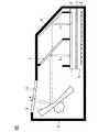
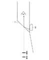
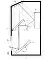
図1は、実施の形態1に係るヘッドアップディスプレイ用の表示装置100の構成を示す断面図であり、図2は表示装置100の使用状態を示す図である。表示装置100は例えば自動車などの車両に搭載される。表示装置100の出力光がフロントガラス11に反射して運転者に届くことにより、運転者はフロントガラス11より前方に虚像を視認するものである。<A. Embodiment 1>
<A-1. Configuration>
FIG. 1 is a cross-sectional view illustrating a configuration of a
表示装置100は、唯一つの表示デバイスとしての液晶表示器1の他、ハーフミラー7、平面鏡6、凹面鏡8を備え、さらにこれらの構成要素を位置決めして格納する筐体9を備えている。 The
液晶表示器1は、バックライトの他、バックライトの上に配置された液晶パネル2や、液晶パネル2を駆動する回路基板を備え、さらにこれらの構成要素を位置決めして格納するケース5を備えている。バックライトは、光源としてのLED4と、LED4の上に配置された透光性樹脂板3を備えている。 The liquid crystal display 1 includes a backlight, a
液晶パネル2は、液晶の複屈折性を応用した表示部であり、スペーサを挟んで対向基板とTFTアレイ基板を向かい合わせ、周囲をシール材で貼り合わせることにより形成されている。対向基板は、ガラス等の絶縁性基板であって、その上に着色層、遮光層、対向電極等が形成されている。TFTアレイ基板もガラス等の絶縁性基板であって、その上にスイッチング素子となる薄膜トランジスタ(TFT)や画素電極等が形成されている。 The
シール材で貼り合わせた対向基板とTFTアレイ基板の周囲には注入口が形成されており、注入口から液晶が注入した後に注入口を封止材で封入することにより、両基板間に液晶が挟持される。 An injection port is formed around the counter substrate and the TFT array substrate bonded together with the sealing material. After the liquid crystal is injected from the injection port, the injection port is sealed with the sealing material, so that the liquid crystal is interposed between the two substrates. It is pinched.
さらに液晶パネル2は、液晶を配向させる配向膜や、偏光板などを備えている。なお、本発明において液晶パネル2には一般的なものを用いるため、詳細な説明は省略する。 Furthermore, the
液晶パネル2を駆動する回路基板には、ガラスエポキシ等に銅パターンが形成され、複数の電子部品が半田実装される。回路基板は固定ネジや、あるいはカシメ、引っ掛け爪等により液晶表示器1のケース5に対して機械的に接続されている。 On the circuit board that drives the
また、回路基板には、外部からの圧力や静電気から保護するため保護カバーが取り付けられている。保護カバーの材料には、アルミニウムやステンレス、亜鉛めっき鋼板などが用いられる。また、保護カバーの回路基板側には、回路基板や回路基板上の電子部品との電気的接触を避けるためにPET等の樹脂製シートが貼り付けられている。保護カバーは液晶表示器1のケース5の内側にネジやカシメなどで機械的に接続されている。また、保護カバーには、回路基板と保護カバーを液晶表示器1に取り付けた状態で回路基板上の可変抵抗を制御することが出来るように、可変抵抗の近傍に孔(貫通孔)を有している。なお、外部からの圧力などが大きくない場合は、保護カバーをPETシートで代用することも出来る。この場合、回路基板との間に絶縁用の樹脂製シートを貼り付ける必要がないため、部品点数を削減できコストが抑えられる。 Further, a protective cover is attached to the circuit board to protect it from external pressure and static electricity. Aluminum, stainless steel, galvanized steel sheet or the like is used as the material for the protective cover. Further, a resin sheet such as PET is attached to the circuit board side of the protective cover in order to avoid electrical contact with the circuit board and electronic components on the circuit board. The protective cover is mechanically connected to the inside of the
次に、バックライトの構成について説明する。ケース5の底面には光源基板が設けられ、光源基板上に所定の間隔で複数のLED4が点状光源として実装されている。光源基板には、LED4に電力を供給するための回路パターンが形成されている。光源基板を厚さの薄いフラットケーブルで構成すれば、LED4からの熱を効率良く周囲に伝えることが出来る他、光源基板とLED4からなる光源装置としての外形サイズを小さくすることが可能である。 Next, the configuration of the backlight will be described. A light source substrate is provided on the bottom surface of the
光源にはLEDの他、レーザーダイオード(Laser Diode)などの点状光源や、冷陰極管(Cold Cathode Fluorescent Lamp)などの線光源がある。LEDには、青色等の単色を発光する半導体発光素子や、半導体発光素子から発する青色光の一部を吸収して黄色光を発する蛍光体からなる擬似白色LED等を用いることが可能である。また、赤色、緑色、青色の各色光を夫々発光する単色LEDを備え、これらの単色光を合成して白色光を形成しても良い。なお本実施の形態では、擬似白色LEDを点状光源として使用する。 In addition to LEDs, there are point light sources such as laser diodes and linear light sources such as cold cathode fluorescent lamps. As the LED, it is possible to use a semiconductor light emitting element that emits a single color such as blue, or a pseudo white LED made of a phosphor that emits yellow light by absorbing part of the blue light emitted from the semiconductor light emitting element. Further, single-color LEDs that respectively emit red, green, and blue light may be provided, and white light may be formed by combining these single-color lights. In the present embodiment, a pseudo white LED is used as a point light source.
透光性樹脂板3のLED4側面には、LED4からの光を集光するためにLEDの発光点を焦点とする片凸レンズが形成されている。また、レンズの凸形状を達成するためには、LED発光点を焦点とするフレネルレンズを用いても良い。なお、透光性樹脂板の上には任意で光学シートなどを配備することが出来る。また、液晶表示器の輝度配向を整えるため、視野角調整フィルムなどを用いることも出来る。 On the side surface of the
本実施の形態では、透光性樹脂板3を有する直下型のバックライトを用いているが、光を面状に伝播する導光板を備え、導光板の端面にLEDを配置し、LEDからの光を導光板内で伝播して面状に出力するエッジライト方式のバックライトを用いても良い。 In this embodiment, a direct-type backlight having a
ケース5は、LED4から放出される熱を伝導させて周囲に放出する機能を有している。また、ケース5は液晶表示器1の各部材を収納し、これらを所定の位置に位置決めする必要があることから、高い強度が求められる。そのため、ケース5の材料は強度が強く、熱伝導性が高い金属であることが望ましい。特に、熱伝導性が高いアルミやアルミ合金を用いることで、効率良くLED4からの熱を拡散でき、LED4の温度を下げることが出来る。また、ケース5に広がった熱を効率よく大気に逃がすために、ケース5は筐体9と接触して配置することが望ましい。 The
次に、液晶表示器1以外の表示装置の構成部材について説明する。ハーフミラー7は、光の一部を透過し一部を正反射する特性を有し、ガラス基板などに反射膜を蒸着形成する金属膜方式と誘導体多層膜方式がある。金属膜の材料としては、クロムやアルミ、銀等が用いられる。ハーフミラー7は液晶表示器1上に設けられる。図1において液晶パネル2を左右に2分割し、左側を第1表示領域、右側を第2表示領域とすると、ハーフミラー7は第1表示領域上で筐体9に位置決めされ、第1表示領域からの出射光を凹面鏡8に向けて反射する。なお、本明細書では他の図でも同様に、液晶表示器1における液晶パネル2の左側を第1表示領域、右側を第2表示領域として説明する。 Next, components of the display device other than the liquid crystal display 1 will be described. The
凹面鏡8は、ハーフミラー7の光を筐体9の窓部10から外部に反射する。凹面鏡は回転軸を有しており、ステッピングモータ等で当該回転軸を中心に回転させることによって、取り付け角度の調整が可能である。凹面鏡8は、ガラスやポリカーボネート等にアルミを蒸着させて反射膜を形成したものである。球面よりも非球面で凹面鏡8を形成することにより、虚像のひずみを少なくすることが出来る。 The
ハーフミラー7を中心として凹面鏡8と対向する側、すなわち液晶パネル2の第2表示領域上には、平面鏡6が設けられている。平面鏡6はガラスやポリカーボネート等にアルミを蒸着させて反射膜を形成したものである。 On the side facing the
以上に構成を説明した液晶表示器1、ハーフミラー7、凹面鏡8、平面鏡6は筐体9内に設けられ、筐体9により位置決めされている。筐体9は放熱性が高く、強度が強いアルミやマグネシウムダイキャスト等からなる。また、筐体9は透光性樹脂からなるポリカーボネートなどがはめ込まれて形成された窓部10を有しており、窓部10から凹面鏡8の反射光が出射する。 The liquid crystal display 1, the
<A−2.動作>
次に、図1を参照しながらLED4の出射光が虚像として運転者に視認されるまでを説明する。<A-2. Operation>
Next, the process until the driver visually recognizes the light emitted from the
LED4から上方へ出射した光は、透光性樹脂板3のLED4側に形成されたフレネルレンズ等で集光され、透光性樹脂板3と垂直な向きの平行光になる。この平行光は、透光性樹脂板3の上部に設けられた光学シート(図示せず)を通過して液晶パネル2に入射する。 The light emitted upward from the
ここで、液晶パネル2の第1表示領域を透過した光は、液晶パネル2に対して約45°の傾きで配置されたハーフミラー7で反射され、さらに凹面鏡8で反射される。凹面鏡8で反射された光は窓部10から筐体9外部に出射し、図2に示すようにフロントガラス11に反射して運転者へ導かれる。 Here, the light transmitted through the first display area of the
また、液晶パネル2の第2表示領域を透過した光は、液晶パネル2に対して約45°の傾きで配置された平面鏡6で反射される。この反射光はハーフミラー7を透過し、さらに凹面鏡8で反射される。凹面鏡8で反射された光は窓部10から筐体9外部に出射し、図2に示すようにフロントガラス11に反射して運転者へ導かれる。なお、図2に示すフロントガラス11は、表示装置100の出力光を運転者に向けて反射する透過基板の一例である。すなわち、表示装置100と透過基板によりヘッドアップディスプレイシステムを構成している。 Further, the light transmitted through the second display area of the
液晶パネル2の第1、第2表示領域を透過した光はいずれも運転者へ導かれるが、ハーフミラー7に至るまでの光路L1,L2に差がある。そのため、液晶パネル2の第1表示領域を透過した光は図2に示す虚像1となり、第2表示領域を透過した光は図2に示す虚像2となる。虚像1と虚像2の間の距離は、L2−L1に比例して大きくなる特性を有する。つまり、L2−L1を大きくすることで、虚像1と虚像2の間隔を広げることが出来る。 The light transmitted through the first and second display areas of the
また、凹面鏡8の曲率を大きくすることで、運転者から虚像1,2までの距離を大きくすることが出来る。反対に凹面鏡8の曲率を小さくすると、運転者から虚像1,2までの距離を小さくすることが出来る。凹面鏡8の曲率を大きくすると虚像がより運転者から遠方に外景と重複して表示される。そのため、運転者は外景を視認したままピントを移動することなく虚像を視認することが出来るので、虚像から走行スピード等の情報をより安全に取得することができる。 Further, by increasing the curvature of the
また、凹面鏡8に替えて平面鏡を用いてもよい。平面鏡は凹面鏡と同様、ガラスやポリカーボネート等にアルミを蒸着させて反射面を形成したものであり、凹面鏡に比べて、製造が容易でコストが安く、一般的な材料であるため、入手性がよい。なお、平面鏡を用いる場合、ハーフミラー7とフロントガラス11間に凹レンズを備え、凹レンズの曲率を調整することによって、運転者と虚像までの距離を任意で変更することが可能である。 Further, a plane mirror may be used instead of the
また、平面鏡6に替えて凹面鏡を用い、凹面鏡の曲率を大きくすることにより、虚像1と虚像2の距離を更に大きくすることができる。これにより、運転者が近くを見た場合は虚像1を、遠くを見た場合は虚像2を視認できる為、広い範囲で運転者が画像を見ることが出来る。 Moreover, the distance between the virtual image 1 and the
また、液晶パネル2の第2表示領域からハーフミラー7に至る光路L2上に凹レンズ(図示せず)をさらに備え、当該凹レンズの曲率を調整することにより虚像1と虚像2の距離を大きくすることが出来る。また、光路L2上に複数枚の凹レンズを重ねることによっても、虚像1と虚像2の間隔を大きくすることが出来る。 Further, a concave lens (not shown) is further provided on the optical path L2 from the second display area of the
また、液晶パネル2の第1表示領域と第2表示領域で表示する画像は、同一内容でも異なる内容でも良い。但し、第1表示領域と第2表示領域の双方で同じ画像を表示する場合には、運転者に広く視認させる効果を奏するため、例えば走行速度値等の運転上重要な情報は、第1表示領域と第2表示領域の双方で表示することが望ましい。 The images displayed in the first display area and the second display area of the
なお、表示装置100の表示手段には液晶表示器を用いたが、有機ELやその他の表示デバイスを用いても良い。 In addition, although the liquid crystal display was used for the display means of the
<A−3.変形例>
図3は、実施の形態1の変形例に係る表示装置101の構成を示す断面図である。図3において、図1に示した表示装置100と同一の構成要素には同一の参照符号を付している。<A-3. Modification>
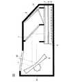
FIG. 3 is a cross-sectional view illustrating a configuration of a
表示装置101は、表示装置100の平面鏡6に替えて複数段の平面鏡6a,6b,6cを備えたものである。平面鏡6a,6b,6cは、いずれも液晶パネル2と45度の角度で設けられている。平面鏡6aは液晶パネル2の第2表示領域の上方に設けられ、その法線方向は図3の右下方向となる。平面鏡6bは平面鏡6aの次段の平面鏡であり、その法線方向は図3の左下方向となる。平面鏡6cは平面鏡6bの次段の平面鏡であり、その法線方向は図3の左上方向となる。なお、平面鏡6a,6b,6c以外の表示装置101の構成は、表示装置100と同様であるので、説明を省略する。 The
液晶パネル2の第2表示領域から放たれた光は、まず平面鏡6aで反射される。平面鏡6aで反射された光は平面鏡6bで反射される。さらに平面鏡6cで反射されて、ハーフミラー7に入射する。 The light emitted from the second display area of the
このように複数の平面鏡6a,6b,6cを用いることにより、一つの平面鏡6を用いる表示装置100に比べて液晶パネル2の第2表示領域からハーフミラー7までの光路L2を大きくすることができる。そのため、図4に示すように虚像1と虚像2の間隔を大きくすることができる。 As described above, by using the plurality of
なお、平面鏡6a,6b,6cに代えて凹面鏡を用いた場合には、より虚像1,2の間隔を大きくすることが出来る。 When a concave mirror is used instead of the plane mirrors 6a, 6b, 6c, the interval between the
また、3つの平面鏡6a,6b,6cを用いた場合を例に表示装置101を説明したが、平面鏡の枚数はこれに限らない。平面鏡の枚数を多くして液晶パネル2の第2表示領域からハーフミラー7までの光路を長くするほど、虚像1,2の間隔を大きくすることが出来る。 Further, the
<A−4.効果>
本実施の形態の表示装置100,101は、ヘッドアップディスプレイ装置用の表示装置であって、第1表示領域と第2表示領域を含む一の表示領域を有する液晶表示器1(表示手段)と、液晶表示器1の第1表示領域から出射された第1出射光を反射するハーフミラー7と、液晶表示器1の第2表示領域から出射された第2出射光をハーフミラー7の方向に反射する平面鏡6(第1の反射板)と、を備え、ハーフミラー7で反射した第1出射光と、ハーフミラー7を透過した第2出射光を重ねて装置外部に導出する。一つの液晶表示器1を用いて2つの虚像を表示するので、ヘッドアップディスプレイ用の表示装置100,101を簡単な構造で実現できる。<A-4. Effect>
また、本実施の形態の表示装置100,101は、ハーフミラー7で反射した第1出射光と、ハーフミラー7を透過した第2出射光を重ねて装置外部に反射する凹面鏡8(第2の反射板)をさらに備えるので、使用者に対して虚像を表示することが可能である。 In addition, the
また、表示装置101は、第2出射光を順次に反射する複数の平面鏡6a,6b,6c(第1の反射板)を備えるので、第2出射光のハーフミラー7に至る光路を第1出射光に比べて長くすることが出来る。その結果、2つの虚像の間隔を広げることが出来る。 In addition, the
また、平面鏡6,6a,6b,6cの代わりに凹面鏡を用いることによっても、2つの虚像の間隔を広げることが出来る。 Moreover, the space | interval of two virtual images can be expanded also by using a concave mirror instead of the plane mirrors 6, 6a, 6b, 6c.
あるいは、液晶表示器1の第2表示領域からハーフミラー7に至る第2出射光の光路間に凹レンズを設けることにより、2つの虚像の間隔を広げることが出来る。 Alternatively, by providing a concave lens between the optical paths of the second outgoing light from the second display area of the liquid crystal display 1 to the
実施の形態1のヘッドアップディスプレイシステムは、表示装置100と、表示装置100から導出された光を使用者側に反射するフロントガラス11(透過基板)とを備える。表示装置100の出力光を透過基板上に投射することにより、使用者は透過基板より前方に虚像を視認する。 The head-up display system according to the first embodiment includes a
<B.実施の形態2>
<B−1.構成>
図5は、実施の形態2に係るヘッドアップディスプレイ用の表示装置102の構成を示す断面図である。図5において、図1に示した表示装置100と同一の構成要素には同一の参照符号を付している。<B. Second Embodiment>
<B-1. Configuration>
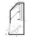
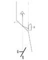
FIG. 5 is a cross-sectional view illustrating a configuration of the
表示装置102は、実施の形態1に係る表示装置100の構成に加えて偏角素子12を備えたものである。偏角素子12は液晶パネル2の第2表示領域上に設けられる。特に、その入射面は液晶パネル2に平行であって第2表示領域をすべて覆うように形成される。偏角素子12の出射面は入射面と角度αをなしている。偏角素子12は、透過性を有するガラス、アクリル、ポリカーボネート(PC)等からなり、入光面、出光面ともに鏡面である。また、偏角素子12の材料の屈折率をn、空気の屈折率を1と仮定すると、入射面と出射面がなす角αは、偏角素子12内での全反射を避けるためにα<sin−1(1/n)を満たす必要がある。The
また、平面鏡6が液晶パネル2となす角度をβとすると、β=45+(sin−1(nsinα)−α)/2とすることにより、偏角素子12の出射光を平面鏡6で反射させてハーフミラー7に効率よく入射させることができる。Further, if the angle formed by the
偏角素子12以外の表示装置102の構成は、実施の形態1に係る表示装置100と同様であるので、説明を省略する。 Since the configuration of the
<B−2.動作>
次に、図5を参照しながらLED4の出射光が虚像として運転者に視認されるまでを説明する。LED4から液晶パネル2までの光路と、液晶パネル2の第1表示領域から運転者までの光路については、実施の形態1と同様であるので説明を省略する。<B-2. Operation>
Next, with reference to FIG. 5, a description will be given of how the emitted light of the
液晶パネル2の第2表示領域を透過した光は、偏角素子12に入射し、偏角素子12から出射する際に図5の右方向に屈折する。屈折した光は平面鏡6で反射され、ハーフミラー7を透過し、さらに凹面鏡8で反射される。凹面鏡8で反射された光は窓部10から筐体9外部に出射し、図6に示すようにフロントガラス11に反射して運転者へ導かれる。なお、図6に示すフロントガラス11は、表示装置102の出力光を運転者に向けて反射する透過基板の一例である。すなわち、表示装置102と透過基板によりヘッドアップディスプレイシステムを構成している。 The light transmitted through the second display region of the
液晶パネル1の第1表示領域を透過した光による虚像1は、実施の形態1と同様に視認される。一方、第2表示領域の透過光による虚像2は、虚像1と側面視で角度αをなして視認される。このように虚像2は虚像1に対して傾斜して表示されるため、運転者は立体的な画像を視認することとなる。 The virtual image 1 by the light transmitted through the first display area of the liquid crystal panel 1 is visually recognized as in the first embodiment. On the other hand, the
<B−3.変形例>
図6に示した虚像2の虚像1に対する傾きは、偏角素子12の入射面と出射面がなす角度αに起因する。しかし、当該角度αには全反射を避けるためにα<sin−1(1/n)の制限がある。そこで、実施の形態2の変形例に係る表示装置103では複数の偏角素子を用いることにより、虚像2の虚像1に対する傾斜を大きくすることを可能にする。<B-3. Modification>
The inclination of the
図7は、実施の形態2の変形例に係る表示装置103の構成を示す断面図である。図7において、図5に示した表示装置102と同一の構成要素には同一の参照符号を付している。 FIG. 7 is a cross-sectional view illustrating a configuration of a
表示装置103は、表示装置102の構成に加えて平面鏡6の前段に偏角素子13をさらに備えるものである。偏角素子13は、入射面と出射面が角度γ(γ<sin−1(1/n))をなしている。In addition to the configuration of the
液晶パネル2の第2表示領域から出射した光は、偏角素子12で角度αだけ屈折した後、さらに偏角素子13で角度γだけ屈折するので、合わせて角度(α+γ)だけ屈折する。よって、側面視において虚像2は虚像1に対して角度α+γだけ傾く。なお、液晶パネル2の第2表示領域からハーフミラー7に至る光路上に設けられる偏角素子は図7に示す2個に限らず、さらに多くの偏角素子を設けることによって、図8に示すように虚像1と虚像2のなす角を垂直に近づけても良い。これにより、1つの偏角素子12を備える表示装置102に比べて、より立体感がある表示を運転者に提供することが可能になる。 The light emitted from the second display area of the
<B−4.効果>
実施の形態2に係る表示装置102は、液晶表示器1の第2表示領域からハーフミラー7に至る第2出射光の光路上に設けられ、透光性を有し、第2出射光の出射面が入射面に対して傾斜した偏角素子12を備えるので、第2出射光が偏角素子12,13で屈折し、虚像2が虚像1に対して傾斜して表示される。よって、立体的な表示が可能となる。<B-4. Effect>
The
また、偏角素子12の屈折率をnとした場合に、偏角素子12,13の出射面と入射面がなす角度αは、α<sin−11/nとすることにより、第2出射光が偏角素子12,13内で全反射することを防ぐ。In addition, when the refractive index of the
また、表示装置103は、複数の偏角素子12,13を備えるので、虚像2を虚像1に対して大きく傾けて、より立体的な表示を可能にする。 Further, since the
<C.実施の形態3>
<C−1.構成、動作>
図9は、実施の形態3に係るヘッドアップディスプレイ用の表示装置104の構成を示す断面図である。表示装置104はデュアルディスプレイ15の他、ハーフミラー17、平面鏡16、凹面鏡8、偏光素子14を備える。<
<C-1. Configuration, operation>
FIG. 9 is a cross-sectional view illustrating a configuration of the
デュアルディスプレイ15は、見る角度に応じて異なる画像を表示することが可能な表示デバイスである。デュアルディスプレイ15は、例えばTFT液晶ディスプレイ上に視差バリアを設けて構成され、バックライトからの光を視差バリアで左右に分離させることで2方向に異なる表示を実現する。図9で、デュアルディスプレイ15から左上方向への出射光を第1画像光、右上方向への出射光を第2画像光とする。 The
偏角素子14は、デュアルディスプレイ15の第1画像光を屈折できるよう、図9においてデュアルディスプレイ15の左上方に設けられている。また、偏角素子14の上方には偏角素子14からの光を凹面鏡8の方向へ反射するための最適な角度でハーフミラー17が配置されている。 The
一方、平面鏡16は図9においてデュアルディスプレイ15の右上方に設けられ、デュアルディスプレイ15の第2画像光をハーフミラー17の方向へ反射するための最適な角度で配置されている。 On the other hand, the
ハーフミラー17は偏角素子14からの第1画像光と平面鏡16からの第2画像光を合成して凹面鏡8に出力する。凹面鏡8は、ハーフミラー17からの出力光を装置外部に反射する。凹面鏡8で装置外部に反射された光は、図10に示すように例えばフロントガラス11へ投影され、運転者はフロントガラス11の投影画像を虚像として視認する。第2画像光による虚像2は、第1画像光による虚像1に対して側面視で傾斜するので、運転者に立体的な画像を提供することが可能となる。なお、図10に示すフロントガラス11は、表示装置104の出力光を運転者に向けて反射する透過基板の一例である。すなわち、表示装置104と透過基板によりヘッドアップディスプレイシステムを構成している。 The
本実施の形態の表示装置104はデュアルディスプレイ15を用いるので、実施の形態1,2のように画面を2分割する必要が無く、画面全体の画像をそれぞれ別の虚像としてフロントガラスに投影することができる。これにより、大きい画像を運転者に視認させることができる。 Since the
なお、図9ではデュアルディスプレイ15とハーフミラー17の間に偏角素子14を設けたが、さらにデュアルディスプレイ15と平面鏡16の間に設けても良い。これにより、運転者が視認する虚像1と虚像2の側面視における角度がより垂直に近づくので、より立体的な画像となる。また、偏角素子は第1画像光のハーフミラー17に至る光路上、及び第2画像光のハーフミラー17に至る光路上で夫々複数設けられていても良い。 In FIG. 9, the
また、デュアルディスプレイ15には液晶デバイスのみならず、有機ELやその他の表示デバイスを用いることが可能である。 The
なお、本発明は、その発明の範囲内において、各実施の形態を自由に組み合わせたり、各実施の形態を適宜、変形、省略することが可能である。 It should be noted that the present invention can be freely combined with each other within the scope of the invention, and each embodiment can be appropriately modified or omitted.
<C−2.効果>
実施の形態3の表示装置104は、ヘッドアップディスプレイ装置用の表示装置であって、表示面を有し、当該表示面から第1の仰角範囲に第1画像を表示し、第2の仰角範囲に第2画像を表示するデュアルディスプレイ15と、第1の仰角範囲に設けられ、第1画像の表示光を反射するハーフミラー7と、第2の仰角範囲に設けられ、第2画像の表示光をハーフミラー7の方向に反射する第1の反射板6と、を備え、ハーフミラー7で反射した第1画像の表示光と、ハーフミラー7を透過した第2画像の表示光を重ねて装置外部に導出する。一つのデュアルディスプレイ15を用いて2つの虚像を表示するので、ヘッドアップディスプレイ用の表示装置104を簡単な構造で実現できる。<C-2. Effect>
The
また、表示装置104は、ハーフミラー7で反射した第1画像の表示光と、ハーフミラー7を透過した第2画像の表示光を重ねて装置外部に反射する凹面鏡8(第2の反射板)を備えるので、使用者に対して虚像を表示することが可能である。 Further, the
又、表示装置104は、デュアルディスプレイ15の表示面からハーフミラー7に至る第1画像の表示光の光路上に設けられ、透光性を有し、第1画像の表示光の出射面が入射面に対して傾斜した偏角素子14を備えるので、虚像の一方を他方に対して傾斜させて表示することによって立体的な表示が可能となる。 Further, the
デュアルディスプレイ15の表示面から第1の反射板6に至る第2画像の表示光の光路上に設けられ、透光性を有し、第2画像の表示光の出射面が入射面に対して傾斜した偏角素子をさらに備えるので、虚像の一方を他方に対してさらに大きく傾斜させて表示することにより、より立体的な表示が可能となる。 Provided on the optical path of the display light of the second image from the display surface of the
視差バリア方式のTFT液晶ディスプレイでデュアルディスプレイ15を構成することも可能である。 It is also possible to configure the
1 液晶表示器、2 液晶パネル、3 透光性樹脂板、4 LED、5 ケース、6,6a,6b,6c,16 平面鏡、7,17 ハーフミラー、8 凹面鏡、9 筐体、10 窓部、11 フロントガラス、12,13,14 偏角素子、15 デュアルディスプレイ、100,101,102,103,104 表示装置。 DESCRIPTION OF SYMBOLS 1 Liquid crystal display device, 2 Liquid crystal panel, 3 Translucent resin board, 4 LED, 5 Case, 6, 6a, 6b, 6c, 16 Plane mirror, 7, 17 Half mirror, 8 Concave mirror, 9 Case, 10 Window part, 11 Windshield, 12, 13, 14 Declination element, 15 Dual display, 100, 101, 102, 103, 104 Display device.
Claims (16)
Translated fromJapanese第1表示領域と第2表示領域を含む一の表示領域を有する表示手段と、
前記表示手段の前記第1表示領域から出射された第1出射光を反射するハーフミラーと、
前記表示手段の前記第2表示領域から出射された第2出射光を前記ハーフミラーの方向に反射する第1の反射板と、を備え、
前記ハーフミラーで反射した前記第1出射光と、前記ハーフミラーを透過した前記第2出射光を重ねて装置外部に導出する、
表示装置。A display device for a head-up display device,
Display means having one display area including a first display area and a second display area;
A half mirror that reflects the first emitted light emitted from the first display region of the display means;
A first reflector that reflects the second emitted light emitted from the second display area of the display means in the direction of the half mirror;
The first emitted light reflected by the half mirror and the second emitted light transmitted through the half mirror are overlapped and led out to the outside of the apparatus.
Display device.
請求項1に記載の表示装置。A second reflecting plate for reflecting the first outgoing light reflected by the half mirror and the second outgoing light transmitted through the half mirror to reflect outside the apparatus;
The display device according to claim 1.
請求項2に記載の表示装置。The second reflector is a concave mirror;
The display device according to claim 2.
請求項1〜3のいずれかに記載の表示装置。A plurality of the first reflectors that sequentially reflect the second emitted light;
The display device according to claim 1.
請求項1〜4のいずれかに記載の表示装置。The first reflector is a concave mirror;
The display apparatus in any one of Claims 1-4.
請求項1〜4のいずれかに記載の表示装置。A concave lens provided between the optical paths of the second emitted light from the second display area of the display means to the half mirror;
The display apparatus in any one of Claims 1-4.
請求項1〜6のいずれかに記載の表示装置。A declination element provided on an optical path of the second emitted light from the second display region to the half mirror, having translucency, and an exit surface of the second emitted light being inclined with respect to an incident surface. In addition,
The display device according to claim 1.
請求項7に記載の表示装置。When the refractive index of the declination element is n, the angle α formed by the exit surface and the incident surface of the declination element satisfies α <sin−1 (1 / n).
The display device according to claim 7.
請求項8に記載の表示装置。A plurality of the declination elements are provided,
The display device according to claim 8.
表示面を有し、当該表示面から第1の仰角範囲に第1画像を表示し、第2の仰角範囲に第2画像を表示するデュアルディスプレイと、
前記第1の仰角範囲に設けられ、前記第1画像の表示光を反射するハーフミラーと、
前記第2の仰角範囲に設けられ、前記第2画像の表示光を前記ハーフミラーの方向に反射する第1の反射板と、を備え、
前記ハーフミラーで反射した前記第1画像の表示光と、前記ハーフミラーを透過した前記第2画像の表示光を重ねて装置外部に導出する、
表示装置。A display device for a head-up display device,
A dual display having a display surface, displaying a first image in a first elevation angle range from the display surface, and displaying a second image in a second elevation angle range;
A half mirror provided in the first elevation angle range and reflecting display light of the first image;
A first reflector that is provided in the second elevation angle range and reflects the display light of the second image in the direction of the half mirror;
The display light of the first image reflected by the half mirror and the display light of the second image transmitted through the half mirror are overlapped and led out of the apparatus.
Display device.
請求項10に記載の表示装置。A second reflecting plate for reflecting the display light of the first image reflected by the half mirror and the display light of the second image transmitted through the half mirror to be reflected outside the apparatus;
The display device according to claim 10.
請求項11に記載の表示装置。The second reflector is a concave mirror;
The display device according to claim 11.
請求項10〜12のいずれかに記載の表示装置。Provided on the optical path of the display light of the first image from the display surface of the dual display to the half mirror, has translucency, and the exit surface of the display light of the first image is relative to the incident surface Further comprising an inclined declination element,
The display device according to claim 10.
請求項10〜13のいずれかに記載の表示装置。Provided on the optical path of the display light of the second image from the display surface of the dual display to the first reflector, has translucency, and the exit surface of the display light of the second image is the incident surface Further comprising a declination element inclined with respect to
The display device according to claim 10.
請求項10〜14のいずれかに記載の表示装置。The dual display is a parallax barrier TFT liquid crystal display,
The display device according to claim 10.
前記表示装置から導出された光を使用者側に反射する透過基板と、
を備えたヘッドアップディスプレイシステム。A display device according to any one of claims 1 to 15,
A transmissive substrate that reflects light derived from the display device to a user side;
Head-up display system with
Priority Applications (2)
| Application Number | Priority Date | Filing Date | Title |
|---|---|---|---|
| JP2012085240AJP6004706B2 (en) | 2012-04-04 | 2012-04-04 | Display device and head-up display system provided with the same |
| US13/791,639US9188779B2 (en) | 2012-04-04 | 2013-03-08 | Display apparatus and head-up display system having the same |
Applications Claiming Priority (1)
| Application Number | Priority Date | Filing Date | Title |
|---|---|---|---|
| JP2012085240AJP6004706B2 (en) | 2012-04-04 | 2012-04-04 | Display device and head-up display system provided with the same |
Publications (2)
| Publication Number | Publication Date |
|---|---|
| JP2013214008Atrue JP2013214008A (en) | 2013-10-17 |
| JP6004706B2 JP6004706B2 (en) | 2016-10-12 |
Family
ID=49292108
Family Applications (1)
| Application Number | Title | Priority Date | Filing Date |
|---|---|---|---|
| JP2012085240AActiveJP6004706B2 (en) | 2012-04-04 | 2012-04-04 | Display device and head-up display system provided with the same |
Country Status (2)
| Country | Link |
|---|---|
| US (1) | US9188779B2 (en) |
| JP (1) | JP6004706B2 (en) |
Cited By (44)
| Publication number | Priority date | Publication date | Assignee | Title |
|---|---|---|---|---|
| JP2014164066A (en)* | 2013-02-25 | 2014-09-08 | Denso Corp | Head-up display device |
| WO2015190157A1 (en)* | 2014-06-13 | 2015-12-17 | 三菱電機株式会社 | Virtual image display device |
| JP2016103008A (en)* | 2014-11-12 | 2016-06-02 | 日本精機株式会社 | Head-up display device |
| WO2016108932A1 (en)* | 2014-12-31 | 2016-07-07 | Puredepth Inc. | A focal attentional region region displaying a virtualized three dimensional object projected by a multiple layered display system |
| CN106291929A (en)* | 2015-06-10 | 2017-01-04 | 中华映管股份有限公司 | Head-up display module |
| JP2017009738A (en)* | 2015-06-19 | 2017-01-12 | アルプス電気株式会社 | Image display device |
| JP2017021148A (en)* | 2015-07-09 | 2017-01-26 | ホシデン株式会社 | Projection type display device and on-vehicle head-up display using the projection type display device |
| WO2017061039A1 (en)* | 2015-10-09 | 2017-04-13 | 日立マクセル株式会社 | Projection optical system and head-up display device |
| WO2017061019A1 (en)* | 2015-10-09 | 2017-04-13 | 日立マクセル株式会社 | Head-up display device |
| WO2017061040A1 (en)* | 2015-10-09 | 2017-04-13 | 日立マクセル株式会社 | Projection optical system and head-up display device |
| WO2017061041A1 (en)* | 2015-10-09 | 2017-04-13 | 日立マクセル株式会社 | Projection optical system and head-up display device |
| WO2017064797A1 (en)* | 2015-10-15 | 2017-04-20 | 日立マクセル株式会社 | Information display device |
| JP2017077791A (en)* | 2015-10-20 | 2017-04-27 | アルプス電気株式会社 | Image display device |
| WO2017090464A1 (en)* | 2015-11-25 | 2017-06-01 | 日本精機株式会社 | Head-up display |
| WO2017138432A1 (en)* | 2016-02-12 | 2017-08-17 | 日本精機株式会社 | Head-up display device |
| KR20170132067A (en)* | 2016-05-23 | 2017-12-01 | 엘지전자 주식회사 | Head Up Display for Vehicle |
| JP2018012359A (en)* | 2016-07-19 | 2018-01-25 | 日本精機株式会社 | Head-up display device |
| WO2018088360A1 (en)* | 2016-11-08 | 2018-05-17 | 日本精機株式会社 | Head-up display device |
| JP2018097258A (en)* | 2016-12-15 | 2018-06-21 | アルプス電気株式会社 | In-vehicle display device |
| JP2018095157A (en)* | 2016-12-15 | 2018-06-21 | アルプス電気株式会社 | On-vehicle display device |
| US10012836B2 (en) | 2016-05-23 | 2018-07-03 | Lg Electronics Inc. | Head up display for vehicle |
| JPWO2017094427A1 (en)* | 2015-12-01 | 2018-10-11 | 日本精機株式会社 | Head-up display |
| KR101909374B1 (en)* | 2017-02-23 | 2018-10-17 | 엘지전자 주식회사 | Head up display for vehicle |
| KR101902689B1 (en)* | 2017-02-23 | 2018-11-07 | 엘지전자 주식회사 | Head up display for vehicle |
| KR20180123777A (en)* | 2017-05-10 | 2018-11-20 | 주식회사 엘지화학 | Head up display device for vehicle |
| WO2019009243A1 (en) | 2017-07-05 | 2019-01-10 | 京セラ株式会社 | Three-dimensional display device, three-dimensional display system, mobile body, and three-dimensional display method |
| JP2019015892A (en)* | 2017-07-07 | 2019-01-31 | 京セラ株式会社 | Image forming apparatus and movable body |
| JP2019032362A (en)* | 2017-08-04 | 2019-02-28 | アルパイン株式会社 | Head-up display device and navigation device |
| JP2019045605A (en)* | 2017-08-31 | 2019-03-22 | 国立大学法人東北大学 | Head-up display device |
| JPWO2017195740A1 (en)* | 2016-05-09 | 2019-03-28 | 日本精機株式会社 | Head-up display device |
| JP2019051782A (en)* | 2017-09-14 | 2019-04-04 | アルパイン株式会社 | Head-up display |
| DE112017006376T5 (en) | 2017-02-21 | 2019-09-05 | Denso Corporation | FOCUS ON DISPLAY DEVICE |
| JP2019174582A (en)* | 2018-03-28 | 2019-10-10 | 日本精機株式会社 | Display device |
| JPWO2018116896A1 (en)* | 2016-12-20 | 2019-10-24 | 日本精機株式会社 | Head-up display device |
| JP2020012985A (en)* | 2018-07-18 | 2020-01-23 | 日本精機株式会社 | Display unit |
| JP2020510236A (en)* | 2017-03-03 | 2020-04-02 | オステンド・テクノロジーズ・インコーポレーテッド | Split exit pupil head-up display system and method |
| JPWO2021002428A1 (en)* | 2019-07-03 | 2021-01-07 | ||
| US10983423B2 (en) | 2016-12-15 | 2021-04-20 | Dualitas Ltd | Image display device |
| WO2021261438A1 (en)* | 2020-06-24 | 2021-12-30 | 日本精機株式会社 | Head-up display device |
| JP2022179357A (en)* | 2021-05-21 | 2022-12-02 | 中強光電股▲ふん▼有限公司 | head-up display |
| JP2023525841A (en)* | 2020-05-15 | 2023-06-19 | 華為技術有限公司 | Display device and method, and vehicle |
| WO2023204198A1 (en)* | 2022-04-22 | 2023-10-26 | 日本精機株式会社 | Head-up display device |
| WO2024122683A1 (en)* | 2022-12-08 | 2024-06-13 | 엘지전자 주식회사 | Head-up display |
| JP2025503547A (en)* | 2021-12-30 | 2025-02-04 | フューチュラス テクノロジー カンパニー リミテッド | Display device, head-up display and traffic equipment |
Families Citing this family (37)
| Publication number | Priority date | Publication date | Assignee | Title |
|---|---|---|---|---|
| JP2015034919A (en)* | 2013-08-09 | 2015-02-19 | 株式会社デンソー | Information display device |
| JP6127912B2 (en)* | 2013-10-28 | 2017-05-17 | 株式会社Jvcケンウッド | Image display device |
| JP6127923B2 (en)* | 2013-11-06 | 2017-05-17 | 株式会社デンソー | Head-up display device |
| JP6238768B2 (en) | 2014-01-28 | 2017-11-29 | 株式会社日立エルジーデータストレージ | Laser light source module and scanning image display device |
| WO2015152753A1 (en)* | 2014-03-31 | 2015-10-08 | Общество с ограниченной ответственностью "ВэйРэй" | Method of displaying information through automobile windshield, and device for implementing same |
| US9625719B2 (en)* | 2014-09-04 | 2017-04-18 | Yazaki Corporation | Projection display device |
| DE102014013967A1 (en)* | 2014-09-19 | 2016-03-24 | Audi Ag | Head-up display for a motor vehicle, motor vehicle with a head-up display and method for arranging a head-up display in a motor vehicle |
| DE112015004377T5 (en)* | 2014-09-26 | 2017-06-08 | Yazaki Corporation | HEAD-UP DISPLAY DEVICE |
| US11347067B2 (en)* | 2014-12-12 | 2022-05-31 | Young Optics Inc. | Display system |
| JP6558017B2 (en)* | 2015-03-27 | 2019-08-14 | 日本精機株式会社 | Head-up display |
| CN108885344B (en)* | 2016-03-30 | 2021-02-05 | 三菱电机株式会社 | Head-up display device |
| DE102016218582A1 (en) | 2016-09-27 | 2018-03-29 | Bayerische Motoren Werke Aktiengesellschaft | Projection display device with a display in several display levels |
| KR101899981B1 (en)* | 2016-12-02 | 2018-09-19 | 엘지전자 주식회사 | Head Up Display for Vehicle |
| CN109891300B (en)* | 2016-12-19 | 2021-05-28 | 麦克赛尔株式会社 | Head-up display device |
| FR3060776A1 (en)* | 2016-12-20 | 2018-06-22 | Peugeot Citroen Automobiles Sa. | DIGITAL DISPLAY DEVICE FOR VEHICLE |
| DE102017102041A1 (en)* | 2017-02-02 | 2018-08-02 | Visteon Global Technologies, Inc. | display device |
| KR101917021B1 (en) | 2017-02-23 | 2018-11-08 | 엘지전자 주식회사 | Head up display for vehicle |
| DE102017207799B4 (en)* | 2017-05-09 | 2020-08-06 | Audi Ag | Motor vehicle display device and motor vehicle |
| WO2019009252A1 (en)* | 2017-07-04 | 2019-01-10 | 富士フイルム株式会社 | Half mirror |
| CA3013888A1 (en)* | 2017-08-11 | 2019-02-11 | Jason Carl Radel | Transmissive aerial image display |
| KR101934294B1 (en)* | 2017-09-05 | 2019-01-02 | 엘지전자 주식회사 | Display device and vehicle comprising the same |
| CN109581658A (en)* | 2017-09-29 | 2019-04-05 | 中华映管股份有限公司 | head-up display |
| JP6940361B2 (en)* | 2017-10-10 | 2021-09-29 | マクセル株式会社 | Information display device |
| CN107966815B (en)* | 2017-11-20 | 2021-02-19 | 财团法人车辆研究测试中心 | Multi-visual area head-up display device and multi-interlayer imaging mirror thereof |
| DE102017010873B4 (en)* | 2017-11-23 | 2021-10-28 | Maximilian Notar | Apparatus for the position and depth-varying representation of projections or images as well as methods for using the apparatus |
| KR102613488B1 (en)* | 2018-06-26 | 2023-12-14 | 삼성전자주식회사 | Electronic device for adjusting depth of content |
| US20200018977A1 (en)* | 2018-07-13 | 2020-01-16 | Conserve & Associates , Inc. | Display device and automobile head-up display system using the same |
| US11280999B2 (en)* | 2018-07-23 | 2022-03-22 | Maxell, Ltd. | Head-up display |
| DE102018212872A1 (en)* | 2018-08-02 | 2020-02-06 | Bayerische Motoren Werke Aktiengesellschaft | Field of view display device for a motor vehicle |
| US10788669B1 (en) | 2019-04-09 | 2020-09-29 | Denso International America, Inc. | System and assembly for controlling temperature in head-up displays |
| DE102020106159A1 (en) | 2020-03-06 | 2021-09-09 | Bayerische Motoren Werke Aktiengesellschaft | Projection display device with a representation in several display planes |
| JP7424889B2 (en)* | 2020-03-27 | 2024-01-30 | 株式会社小糸製作所 | image display device |
| JP7507611B2 (en)* | 2020-06-05 | 2024-06-28 | 株式会社小糸製作所 | Vehicle display device |
| CN111781727B (en)* | 2020-07-08 | 2021-05-14 | 杜加价 | Vehicle head blind area perspective virtual display device and method based on convex lens/concave mirror |
| CN114077052A (en)* | 2020-08-21 | 2022-02-22 | 未来(北京)黑科技有限公司 | Multilayer image display device, head-up display, and transportation equipment |
| US11169377B1 (en)* | 2020-09-16 | 2021-11-09 | E-Lead Electronic Co., Ltd. | Multi-focal plane head-up display |
| CN115268068A (en)* | 2021-04-29 | 2022-11-01 | 怡利电子工业股份有限公司 | Stereoscopic head-up display device using two directional backlit displays |
Citations (5)
| Publication number | Priority date | Publication date | Assignee | Title |
|---|---|---|---|---|
| JPH04228326A (en)* | 1990-11-28 | 1992-08-18 | Nippondenso Co Ltd | Display device |
| JP2006293184A (en)* | 2005-04-14 | 2006-10-26 | Nippon Telegr & Teleph Corp <Ntt> | Space floating image display device |
| JP2007264529A (en)* | 2006-03-30 | 2007-10-11 | Nippon Seiki Co Ltd | Display device |
| JP2008102449A (en)* | 2006-10-20 | 2008-05-01 | Denso Corp | Display device |
| JP2009053539A (en)* | 2007-08-28 | 2009-03-12 | Sony Corp | Information display device, information display method, and program |
Family Cites Families (3)
| Publication number | Priority date | Publication date | Assignee | Title |
|---|---|---|---|---|
| JPS63164038U (en) | 1987-04-16 | 1988-10-26 | ||
| GB2203855B (en) | 1987-04-16 | 1990-10-03 | Yazaki Corp | Display apparatus for a vehicle |
| US5371510A (en)* | 1990-11-28 | 1994-12-06 | Nippondenso Co., Ltd. | Automotive information display apparatus |
- 2012
- 2012-04-04JPJP2012085240Apatent/JP6004706B2/enactiveActive
- 2013
- 2013-03-08USUS13/791,639patent/US9188779B2/ennot_activeExpired - Fee Related
Patent Citations (5)
| Publication number | Priority date | Publication date | Assignee | Title |
|---|---|---|---|---|
| JPH04228326A (en)* | 1990-11-28 | 1992-08-18 | Nippondenso Co Ltd | Display device |
| JP2006293184A (en)* | 2005-04-14 | 2006-10-26 | Nippon Telegr & Teleph Corp <Ntt> | Space floating image display device |
| JP2007264529A (en)* | 2006-03-30 | 2007-10-11 | Nippon Seiki Co Ltd | Display device |
| JP2008102449A (en)* | 2006-10-20 | 2008-05-01 | Denso Corp | Display device |
| JP2009053539A (en)* | 2007-08-28 | 2009-03-12 | Sony Corp | Information display device, information display method, and program |
Cited By (76)
| Publication number | Priority date | Publication date | Assignee | Title |
|---|---|---|---|---|
| JP2014164066A (en)* | 2013-02-25 | 2014-09-08 | Denso Corp | Head-up display device |
| JPWO2015190157A1 (en)* | 2014-06-13 | 2017-04-20 | 三菱電機株式会社 | Virtual image display device |
| WO2015190157A1 (en)* | 2014-06-13 | 2015-12-17 | 三菱電機株式会社 | Virtual image display device |
| US10254551B2 (en) | 2014-06-13 | 2019-04-09 | Mitsubishi Electric Corporation | Virtual image display device |
| JP2016103008A (en)* | 2014-11-12 | 2016-06-02 | 日本精機株式会社 | Head-up display device |
| WO2016108932A1 (en)* | 2014-12-31 | 2016-07-07 | Puredepth Inc. | A focal attentional region region displaying a virtualized three dimensional object projected by a multiple layered display system |
| US10228570B2 (en) | 2014-12-31 | 2019-03-12 | Pure Depth Limited | Focal attentional region displaying a virtualized three dimensional object projected by a multiple layered display system |
| CN106291929A (en)* | 2015-06-10 | 2017-01-04 | 中华映管股份有限公司 | Head-up display module |
| JP2017027004A (en)* | 2015-06-10 | 2017-02-02 | 中華映管股▲ふん▼有限公司 | Head-up display module |
| US9791695B2 (en) | 2015-06-10 | 2017-10-17 | Chunghwa Picture Tubes, Ltd. | Head-up display module |
| JP2017009738A (en)* | 2015-06-19 | 2017-01-12 | アルプス電気株式会社 | Image display device |
| JP2017021148A (en)* | 2015-07-09 | 2017-01-26 | ホシデン株式会社 | Projection type display device and on-vehicle head-up display using the projection type display device |
| JPWO2017061039A1 (en)* | 2015-10-09 | 2018-08-16 | マクセル株式会社 | Projection optical system and head-up display device |
| JPWO2017061019A1 (en)* | 2015-10-09 | 2018-07-05 | マクセル株式会社 | Head-up display device |
| CN111190290A (en)* | 2015-10-09 | 2020-05-22 | 麦克赛尔株式会社 | Head-up display device |
| CN111198442A (en)* | 2015-10-09 | 2020-05-26 | 麦克赛尔株式会社 | Head-up display device |
| US10690911B2 (en) | 2015-10-09 | 2020-06-23 | Maxell, Ltd. | Projection optical system and head-up display device |
| WO2017061041A1 (en)* | 2015-10-09 | 2017-04-13 | 日立マクセル株式会社 | Projection optical system and head-up display device |
| WO2017061019A1 (en)* | 2015-10-09 | 2017-04-13 | 日立マクセル株式会社 | Head-up display device |
| WO2017061039A1 (en)* | 2015-10-09 | 2017-04-13 | 日立マクセル株式会社 | Projection optical system and head-up display device |
| JPWO2017061040A1 (en)* | 2015-10-09 | 2018-08-16 | マクセル株式会社 | Projection optical system and head-up display device |
| WO2017061040A1 (en)* | 2015-10-09 | 2017-04-13 | 日立マクセル株式会社 | Projection optical system and head-up display device |
| US10788665B2 (en) | 2015-10-09 | 2020-09-29 | Maxell, Ltd. | Projection optical system and head-up display device |
| US10578864B2 (en) | 2015-10-09 | 2020-03-03 | Maxell, Ltd. | Head-up display device |
| JPWO2017064797A1 (en)* | 2015-10-15 | 2018-09-06 | マクセル株式会社 | Information display device |
| WO2017064797A1 (en)* | 2015-10-15 | 2017-04-20 | 日立マクセル株式会社 | Information display device |
| US11119315B2 (en) | 2015-10-15 | 2021-09-14 | Maxell, Ltd. | Information display apparatus |
| JP2017077791A (en)* | 2015-10-20 | 2017-04-27 | アルプス電気株式会社 | Image display device |
| JPWO2017090464A1 (en)* | 2015-11-25 | 2018-09-13 | 日本精機株式会社 | Head-up display |
| WO2017090464A1 (en)* | 2015-11-25 | 2017-06-01 | 日本精機株式会社 | Head-up display |
| JPWO2017094427A1 (en)* | 2015-12-01 | 2018-10-11 | 日本精機株式会社 | Head-up display |
| JPWO2017138432A1 (en)* | 2016-02-12 | 2018-12-27 | 日本精機株式会社 | Head-up display device |
| WO2017138432A1 (en)* | 2016-02-12 | 2017-08-17 | 日本精機株式会社 | Head-up display device |
| JPWO2017195740A1 (en)* | 2016-05-09 | 2019-03-28 | 日本精機株式会社 | Head-up display device |
| KR101882082B1 (en)* | 2016-05-23 | 2018-07-25 | 엘지전자 주식회사 | Head Up Display for Vehicle |
| US10012836B2 (en) | 2016-05-23 | 2018-07-03 | Lg Electronics Inc. | Head up display for vehicle |
| KR20170132067A (en)* | 2016-05-23 | 2017-12-01 | 엘지전자 주식회사 | Head Up Display for Vehicle |
| JP2018012359A (en)* | 2016-07-19 | 2018-01-25 | 日本精機株式会社 | Head-up display device |
| US10916224B2 (en) | 2016-11-08 | 2021-02-09 | Nippon Seiki Co., Ltd. | Head-up display device |
| WO2018088360A1 (en)* | 2016-11-08 | 2018-05-17 | 日本精機株式会社 | Head-up display device |
| US11480855B2 (en) | 2016-12-15 | 2022-10-25 | Dualitas Ltd | Image display device |
| JP2018095157A (en)* | 2016-12-15 | 2018-06-21 | アルプス電気株式会社 | On-vehicle display device |
| JP2018097258A (en)* | 2016-12-15 | 2018-06-21 | アルプス電気株式会社 | In-vehicle display device |
| US10983423B2 (en) | 2016-12-15 | 2021-04-20 | Dualitas Ltd | Image display device |
| JP7076065B2 (en) | 2016-12-20 | 2022-05-27 | 日本精機株式会社 | Head-up display device |
| JPWO2018116896A1 (en)* | 2016-12-20 | 2019-10-24 | 日本精機株式会社 | Head-up display device |
| US10859826B2 (en) | 2017-02-21 | 2020-12-08 | Denso Corporation | Head-up display device |
| DE112017006376T5 (en) | 2017-02-21 | 2019-09-05 | Denso Corporation | FOCUS ON DISPLAY DEVICE |
| KR101902689B1 (en)* | 2017-02-23 | 2018-11-07 | 엘지전자 주식회사 | Head up display for vehicle |
| KR101909374B1 (en)* | 2017-02-23 | 2018-10-17 | 엘지전자 주식회사 | Head up display for vehicle |
| US11333884B2 (en) | 2017-02-23 | 2022-05-17 | Lg Electronics Inc. | Head up display for vehicle |
| JP2020510236A (en)* | 2017-03-03 | 2020-04-02 | オステンド・テクノロジーズ・インコーポレーテッド | Split exit pupil head-up display system and method |
| JP7025439B2 (en) | 2017-03-03 | 2022-02-24 | オステンド・テクノロジーズ・インコーポレーテッド | Split exit pupil head-up display system and method |
| KR20180123777A (en)* | 2017-05-10 | 2018-11-20 | 주식회사 엘지화학 | Head up display device for vehicle |
| WO2019009243A1 (en) | 2017-07-05 | 2019-01-10 | 京セラ株式会社 | Three-dimensional display device, three-dimensional display system, mobile body, and three-dimensional display method |
| US11422383B2 (en) | 2017-07-05 | 2022-08-23 | Kyocera Corporation | Three-dimensional display apparatus, three-dimensional display system, mobile body, and three-dimensional display method |
| JP2019015892A (en)* | 2017-07-07 | 2019-01-31 | 京セラ株式会社 | Image forming apparatus and movable body |
| JP2019032362A (en)* | 2017-08-04 | 2019-02-28 | アルパイン株式会社 | Head-up display device and navigation device |
| JP2019045605A (en)* | 2017-08-31 | 2019-03-22 | 国立大学法人東北大学 | Head-up display device |
| JP2019051782A (en)* | 2017-09-14 | 2019-04-04 | アルパイン株式会社 | Head-up display |
| JP2019174582A (en)* | 2018-03-28 | 2019-10-10 | 日本精機株式会社 | Display device |
| JP7155700B2 (en) | 2018-07-18 | 2022-10-19 | 日本精機株式会社 | Display device |
| JP2020012985A (en)* | 2018-07-18 | 2020-01-23 | 日本精機株式会社 | Display unit |
| JPWO2021002428A1 (en)* | 2019-07-03 | 2021-01-07 | ||
| WO2021002428A1 (en)* | 2019-07-03 | 2021-01-07 | 日本精機株式会社 | Head-up display device |
| JP7501533B2 (en) | 2019-07-03 | 2024-06-18 | 日本精機株式会社 | Head-up display device |
| JP2023525841A (en)* | 2020-05-15 | 2023-06-19 | 華為技術有限公司 | Display device and method, and vehicle |
| JP7540642B2 (en) | 2020-05-15 | 2024-08-27 | 華為技術有限公司 | Display device and method, and vehicle |
| US12328534B2 (en) | 2020-05-15 | 2025-06-10 | Huawei Technologies Co., Ltd. | Display apparatus and method, and vehicle |
| JPWO2021261438A1 (en)* | 2020-06-24 | 2021-12-30 | ||
| WO2021261438A1 (en)* | 2020-06-24 | 2021-12-30 | 日本精機株式会社 | Head-up display device |
| JP7685150B2 (en) | 2020-06-24 | 2025-05-29 | 日本精機株式会社 | Head-up display device |
| JP2022179357A (en)* | 2021-05-21 | 2022-12-02 | 中強光電股▲ふん▼有限公司 | head-up display |
| JP2025503547A (en)* | 2021-12-30 | 2025-02-04 | フューチュラス テクノロジー カンパニー リミテッド | Display device, head-up display and traffic equipment |
| WO2023204198A1 (en)* | 2022-04-22 | 2023-10-26 | 日本精機株式会社 | Head-up display device |
| WO2024122683A1 (en)* | 2022-12-08 | 2024-06-13 | 엘지전자 주식회사 | Head-up display |
Also Published As
| Publication number | Publication date |
|---|---|
| JP6004706B2 (en) | 2016-10-12 |
| US9188779B2 (en) | 2015-11-17 |
| US20130265646A1 (en) | 2013-10-10 |
Similar Documents
| Publication | Publication Date | Title |
|---|---|---|
| JP6004706B2 (en) | Display device and head-up display system provided with the same | |
| JP5353203B2 (en) | Head-up display device | |
| JP6638077B2 (en) | Head-up display device and video display device therefor | |
| US9766455B2 (en) | Head-up display device | |
| EP2755074B1 (en) | Display device for vehicle | |
| JP4883283B2 (en) | Display device | |
| US9417449B2 (en) | Head-up display system | |
| JP6690460B2 (en) | Lighting unit and head-up display device | |
| JP2007264529A (en) | Display device | |
| JP7587417B2 (en) | Space floating image display device and light source device | |
| JP4437675B2 (en) | Lighting device | |
| JP2020134588A (en) | Virtual image display device | |
| JP2006091489A (en) | Display device | |
| JP2007086387A (en) | On-vehicle display device | |
| JP2008257021A (en) | Display device | |
| JP2014238477A (en) | Head-up display device | |
| JP6098868B2 (en) | Head-up display device | |
| US20230115930A1 (en) | Head-up display | |
| TWI802087B (en) | Image generating unit and head-up display therefor | |
| JP2006019027A (en) | Lighting system | |
| JP4985921B2 (en) | Display device | |
| CN212083822U (en) | Augmented reality display optics, glasses and HUD display systems | |
| US20230113774A1 (en) | Head-up display | |
| JP2010243758A (en) | Head-up display | |
| JP7717599B2 (en) | Space-floating image display device |
Legal Events
| Date | Code | Title | Description |
|---|---|---|---|
| A621 | Written request for application examination | Free format text:JAPANESE INTERMEDIATE CODE: A621 Effective date:20150311 | |
| A977 | Report on retrieval | Free format text:JAPANESE INTERMEDIATE CODE: A971007 Effective date:20151215 | |
| A131 | Notification of reasons for refusal | Free format text:JAPANESE INTERMEDIATE CODE: A131 Effective date:20160126 | |
| A521 | Request for written amendment filed | Free format text:JAPANESE INTERMEDIATE CODE: A523 Effective date:20160323 | |
| TRDD | Decision of grant or rejection written | ||
| A01 | Written decision to grant a patent or to grant a registration (utility model) | Free format text:JAPANESE INTERMEDIATE CODE: A01 Effective date:20160809 | |
| A61 | First payment of annual fees (during grant procedure) | Free format text:JAPANESE INTERMEDIATE CODE: A61 Effective date:20160906 | |
| R150 | Certificate of patent or registration of utility model | Ref document number:6004706 Country of ref document:JP Free format text:JAPANESE INTERMEDIATE CODE: R150 | |
| R250 | Receipt of annual fees | Free format text:JAPANESE INTERMEDIATE CODE: R250 | |
| R250 | Receipt of annual fees | Free format text:JAPANESE INTERMEDIATE CODE: R250 | |
| R250 | Receipt of annual fees | Free format text:JAPANESE INTERMEDIATE CODE: R250 | |
| R250 | Receipt of annual fees | Free format text:JAPANESE INTERMEDIATE CODE: R250 | |
| R250 | Receipt of annual fees | Free format text:JAPANESE INTERMEDIATE CODE: R250 | |
| S111 | Request for change of ownership or part of ownership | Free format text:JAPANESE INTERMEDIATE CODE: R313111 | |
| R350 | Written notification of registration of transfer | Free format text:JAPANESE INTERMEDIATE CODE: R350 | |
| R250 | Receipt of annual fees | Free format text:JAPANESE INTERMEDIATE CODE: R250 | |
| R250 | Receipt of annual fees | Free format text:JAPANESE INTERMEDIATE CODE: R250 |