JP2013208397A - Walking motion assistance device - Google Patents
Walking motion assistance deviceDownload PDFInfo
- Publication number
- JP2013208397A JP2013208397AJP2012082388AJP2012082388AJP2013208397AJP 2013208397 AJP2013208397 AJP 2013208397AJP 2012082388 AJP2012082388 AJP 2012082388AJP 2012082388 AJP2012082388 AJP 2012082388AJP 2013208397 AJP2013208397 AJP 2013208397A
- Authority
- JP
- Japan
- Prior art keywords
- user
- hip joint
- force transmission
- walking
- exercise assisting
- Prior art date
- Legal status (The legal status is an assumption and is not a legal conclusion. Google has not performed a legal analysis and makes no representation as to the accuracy of the status listed.)
- Granted
Links
- 230000033001locomotionEffects0.000titleabstractdescription34
- 210000004394hip jointAnatomy0.000claimsabstractdescription82
- 230000005540biological transmissionEffects0.000claimsabstractdescription77
- 230000008859changeEffects0.000claimsabstractdescription36
- 230000004044responseEffects0.000claimsabstractdescription8
- 210000002414legAnatomy0.000claimsdescription26
- 238000003860storageMethods0.000claimsdescription20
- 210000000689upper legAnatomy0.000claimsdescription20
- 210000001624hipAnatomy0.000claimsdescription14
- 230000002265preventionEffects0.000claimsdescription11
- 210000001981hip boneAnatomy0.000claimsdescription7
- 230000009471actionEffects0.000abstractdescription16
- 230000002269spontaneous effectEffects0.000abstractdescription9
- 210000003205muscleAnatomy0.000description21
- 238000005452bendingMethods0.000description18
- 230000003387muscularEffects0.000description16
- 238000001514detection methodMethods0.000description15
- 230000000694effectsEffects0.000description11
- 239000004744fabricSubstances0.000description10
- 210000000629knee jointAnatomy0.000description8
- 230000002829reductive effectEffects0.000description7
- 210000003141lower extremityAnatomy0.000description5
- 238000004804windingMethods0.000description5
- 230000003183myoelectrical effectEffects0.000description4
- 238000012549trainingMethods0.000description4
- 208000027418Wounds and injuryDiseases0.000description3
- 230000006835compressionEffects0.000description3
- 238000007906compressionMethods0.000description3
- 238000010586diagramMethods0.000description3
- 230000005484gravityEffects0.000description3
- 239000000463materialSubstances0.000description3
- 239000002184metalSubstances0.000description3
- 230000002441reversible effectEffects0.000description3
- 210000001217buttockAnatomy0.000description2
- 230000008602contractionEffects0.000description2
- 230000003247decreasing effectEffects0.000description2
- 239000013013elastic materialSubstances0.000description2
- 238000002474experimental methodMethods0.000description2
- 210000001503jointAnatomy0.000description2
- 239000010985leatherSubstances0.000description2
- 238000004519manufacturing processMethods0.000description2
- 238000005259measurementMethods0.000description2
- 230000009467reductionEffects0.000description2
- 210000002027skeletal muscleAnatomy0.000description2
- 208000011580syndromic diseaseDiseases0.000description2
- 230000021542voluntary musculoskeletal movementEffects0.000description2
- 208000029549Muscle injuryDiseases0.000description1
- 208000023178Musculoskeletal diseaseDiseases0.000description1
- 230000003187abdominal effectEffects0.000description1
- 230000002411adverseEffects0.000description1
- 230000032683agingEffects0.000description1
- 238000013459approachMethods0.000description1
- 230000036760body temperatureEffects0.000description1
- 238000012937correctionMethods0.000description1
- 230000006378damageEffects0.000description1
- 238000009826distributionMethods0.000description1
- 230000005489elastic deformationEffects0.000description1
- 210000004177elastic tissueAnatomy0.000description1
- 239000000835fiberSubstances0.000description1
- 210000004392genitaliaAnatomy0.000description1
- 230000006872improvementEffects0.000description1
- 208000014674injuryDiseases0.000description1
- WABPQHHGFIMREM-UHFFFAOYSA-Nlead(0)Chemical compound[Pb]WABPQHHGFIMREM-UHFFFAOYSA-N0.000description1
- 230000003137locomotive effectEffects0.000description1
- 230000003340mental effectEffects0.000description1
- 210000000653nervous systemAnatomy0.000description1
- 239000004745nonwoven fabricSubstances0.000description1
- 230000036961partial effectEffects0.000description1
- 210000004417patellaAnatomy0.000description1
- 210000003314quadriceps muscleAnatomy0.000description1
- 229920005989resinPolymers0.000description1
- 239000011347resinSubstances0.000description1
- 230000000452restraining effectEffects0.000description1
- 239000005060rubberSubstances0.000description1
- 230000035807sensationEffects0.000description1
- 238000000926separation methodMethods0.000description1
- 238000009958sewingMethods0.000description1
- 239000013589supplementSubstances0.000description1
- 230000001502supplementing effectEffects0.000description1
- 229920003002synthetic resinPolymers0.000description1
- 239000000057synthetic resinSubstances0.000description1
- 210000001364upper extremityAnatomy0.000description1
- 230000002747voluntary effectEffects0.000description1
- 238000003466weldingMethods0.000description1
- 239000002759woven fabricSubstances0.000description1
- 230000037303wrinklesEffects0.000description1
Images


Classifications
- A—HUMAN NECESSITIES
- A61—MEDICAL OR VETERINARY SCIENCE; HYGIENE
- A61H—PHYSICAL THERAPY APPARATUS, e.g. DEVICES FOR LOCATING OR STIMULATING REFLEX POINTS IN THE BODY; ARTIFICIAL RESPIRATION; MASSAGE; BATHING DEVICES FOR SPECIAL THERAPEUTIC OR HYGIENIC PURPOSES OR SPECIFIC PARTS OF THE BODY
- A61H3/00—Appliances for aiding patients or disabled persons to walk about
- A—HUMAN NECESSITIES
- A61—MEDICAL OR VETERINARY SCIENCE; HYGIENE
- A61H—PHYSICAL THERAPY APPARATUS, e.g. DEVICES FOR LOCATING OR STIMULATING REFLEX POINTS IN THE BODY; ARTIFICIAL RESPIRATION; MASSAGE; BATHING DEVICES FOR SPECIAL THERAPEUTIC OR HYGIENIC PURPOSES OR SPECIFIC PARTS OF THE BODY
- A61H1/00—Apparatus for passive exercising; Vibrating apparatus; Chiropractic devices, e.g. body impacting devices, external devices for briefly extending or aligning unbroken bones
- A61H1/02—Stretching or bending or torsioning apparatus for exercising
- A61H1/0237—Stretching or bending or torsioning apparatus for exercising for the lower limbs
- A61H1/0244—Hip
- A—HUMAN NECESSITIES
- A63—SPORTS; GAMES; AMUSEMENTS
- A63B—APPARATUS FOR PHYSICAL TRAINING, GYMNASTICS, SWIMMING, CLIMBING, OR FENCING; BALL GAMES; TRAINING EQUIPMENT
- A63B21/00—Exercising apparatus for developing or strengthening the muscles or joints of the body by working against a counterforce, with or without measuring devices
- A63B21/00178—Exercising apparatus for developing or strengthening the muscles or joints of the body by working against a counterforce, with or without measuring devices for active exercising, the apparatus being also usable for passive exercising
- A—HUMAN NECESSITIES
- A63—SPORTS; GAMES; AMUSEMENTS
- A63B—APPARATUS FOR PHYSICAL TRAINING, GYMNASTICS, SWIMMING, CLIMBING, OR FENCING; BALL GAMES; TRAINING EQUIPMENT
- A63B21/00—Exercising apparatus for developing or strengthening the muscles or joints of the body by working against a counterforce, with or without measuring devices
- A63B21/00181—Exercising apparatus for developing or strengthening the muscles or joints of the body by working against a counterforce, with or without measuring devices comprising additional means assisting the user to overcome part of the resisting force, i.e. assisted-active exercising
- A—HUMAN NECESSITIES
- A63—SPORTS; GAMES; AMUSEMENTS
- A63B—APPARATUS FOR PHYSICAL TRAINING, GYMNASTICS, SWIMMING, CLIMBING, OR FENCING; BALL GAMES; TRAINING EQUIPMENT
- A63B21/00—Exercising apparatus for developing or strengthening the muscles or joints of the body by working against a counterforce, with or without measuring devices
- A63B21/005—Exercising apparatus for developing or strengthening the muscles or joints of the body by working against a counterforce, with or without measuring devices using electromagnetic or electric force-resisters
- A63B21/0058—Exercising apparatus for developing or strengthening the muscles or joints of the body by working against a counterforce, with or without measuring devices using electromagnetic or electric force-resisters using motors
- A—HUMAN NECESSITIES
- A63—SPORTS; GAMES; AMUSEMENTS
- A63B—APPARATUS FOR PHYSICAL TRAINING, GYMNASTICS, SWIMMING, CLIMBING, OR FENCING; BALL GAMES; TRAINING EQUIPMENT
- A63B21/00—Exercising apparatus for developing or strengthening the muscles or joints of the body by working against a counterforce, with or without measuring devices
- A63B21/40—Interfaces with the user related to strength training; Details thereof
- A63B21/4001—Arrangements for attaching the exercising apparatus to the user's body, e.g. belts, shoes or gloves specially adapted therefor
- A63B21/4009—Arrangements for attaching the exercising apparatus to the user's body, e.g. belts, shoes or gloves specially adapted therefor to the waist
- A—HUMAN NECESSITIES
- A63—SPORTS; GAMES; AMUSEMENTS
- A63B—APPARATUS FOR PHYSICAL TRAINING, GYMNASTICS, SWIMMING, CLIMBING, OR FENCING; BALL GAMES; TRAINING EQUIPMENT
- A63B21/00—Exercising apparatus for developing or strengthening the muscles or joints of the body by working against a counterforce, with or without measuring devices
- A63B21/40—Interfaces with the user related to strength training; Details thereof
- A63B21/4001—Arrangements for attaching the exercising apparatus to the user's body, e.g. belts, shoes or gloves specially adapted therefor
- A63B21/4011—Arrangements for attaching the exercising apparatus to the user's body, e.g. belts, shoes or gloves specially adapted therefor to the lower limbs
- A—HUMAN NECESSITIES
- A63—SPORTS; GAMES; AMUSEMENTS
- A63B—APPARATUS FOR PHYSICAL TRAINING, GYMNASTICS, SWIMMING, CLIMBING, OR FENCING; BALL GAMES; TRAINING EQUIPMENT
- A63B21/00—Exercising apparatus for developing or strengthening the muscles or joints of the body by working against a counterforce, with or without measuring devices
- A63B21/40—Interfaces with the user related to strength training; Details thereof
- A63B21/4023—Interfaces with the user related to strength training; Details thereof the user operating the resistance directly, without additional interface
- A63B21/4025—Resistance devices worn on the user's body
- A—HUMAN NECESSITIES
- A63—SPORTS; GAMES; AMUSEMENTS
- A63B—APPARATUS FOR PHYSICAL TRAINING, GYMNASTICS, SWIMMING, CLIMBING, OR FENCING; BALL GAMES; TRAINING EQUIPMENT
- A63B21/00—Exercising apparatus for developing or strengthening the muscles or joints of the body by working against a counterforce, with or without measuring devices
- A63B21/40—Interfaces with the user related to strength training; Details thereof
- A63B21/4041—Interfaces with the user related to strength training; Details thereof characterised by the movements of the interface
- A63B21/4043—Free movement, i.e. the only restriction coming from the resistance
- A—HUMAN NECESSITIES
- A63—SPORTS; GAMES; AMUSEMENTS
- A63B—APPARATUS FOR PHYSICAL TRAINING, GYMNASTICS, SWIMMING, CLIMBING, OR FENCING; BALL GAMES; TRAINING EQUIPMENT
- A63B23/00—Exercising apparatus specially adapted for particular parts of the body
- A63B23/035—Exercising apparatus specially adapted for particular parts of the body for limbs, i.e. upper or lower limbs, e.g. simultaneously
- A63B23/04—Exercising apparatus specially adapted for particular parts of the body for limbs, i.e. upper or lower limbs, e.g. simultaneously for lower limbs
- A63B23/0482—Exercising apparatus specially adapted for particular parts of the body for limbs, i.e. upper or lower limbs, e.g. simultaneously for lower limbs primarily by articulating the hip joints
- A—HUMAN NECESSITIES
- A61—MEDICAL OR VETERINARY SCIENCE; HYGIENE
- A61H—PHYSICAL THERAPY APPARATUS, e.g. DEVICES FOR LOCATING OR STIMULATING REFLEX POINTS IN THE BODY; ARTIFICIAL RESPIRATION; MASSAGE; BATHING DEVICES FOR SPECIAL THERAPEUTIC OR HYGIENIC PURPOSES OR SPECIFIC PARTS OF THE BODY
- A61H3/00—Appliances for aiding patients or disabled persons to walk about
- A61H2003/007—Appliances for aiding patients or disabled persons to walk about secured to the patient, e.g. with belts
- A—HUMAN NECESSITIES
- A61—MEDICAL OR VETERINARY SCIENCE; HYGIENE
- A61H—PHYSICAL THERAPY APPARATUS, e.g. DEVICES FOR LOCATING OR STIMULATING REFLEX POINTS IN THE BODY; ARTIFICIAL RESPIRATION; MASSAGE; BATHING DEVICES FOR SPECIAL THERAPEUTIC OR HYGIENIC PURPOSES OR SPECIFIC PARTS OF THE BODY
- A61H2201/00—Characteristics of apparatus not provided for in the preceding codes
- A61H2201/12—Driving means
- A61H2201/1207—Driving means with electric or magnetic drive
- A61H2201/1215—Rotary drive
- A—HUMAN NECESSITIES
- A61—MEDICAL OR VETERINARY SCIENCE; HYGIENE
- A61H—PHYSICAL THERAPY APPARATUS, e.g. DEVICES FOR LOCATING OR STIMULATING REFLEX POINTS IN THE BODY; ARTIFICIAL RESPIRATION; MASSAGE; BATHING DEVICES FOR SPECIAL THERAPEUTIC OR HYGIENIC PURPOSES OR SPECIFIC PARTS OF THE BODY
- A61H2201/00—Characteristics of apparatus not provided for in the preceding codes
- A61H2201/12—Driving means
- A61H2201/1253—Driving means driven by a human being, e.g. hand driven
- A61H2201/1261—Driving means driven by a human being, e.g. hand driven combined with active exercising of the patient
- A—HUMAN NECESSITIES
- A61—MEDICAL OR VETERINARY SCIENCE; HYGIENE
- A61H—PHYSICAL THERAPY APPARATUS, e.g. DEVICES FOR LOCATING OR STIMULATING REFLEX POINTS IN THE BODY; ARTIFICIAL RESPIRATION; MASSAGE; BATHING DEVICES FOR SPECIAL THERAPEUTIC OR HYGIENIC PURPOSES OR SPECIFIC PARTS OF THE BODY
- A61H2201/00—Characteristics of apparatus not provided for in the preceding codes
- A61H2201/16—Physical interface with patient
- A61H2201/1602—Physical interface with patient kind of interface, e.g. head rest, knee support or lumbar support
- A61H2201/1628—Pelvis
- A61H2201/163—Pelvis holding means therefor
- A—HUMAN NECESSITIES
- A61—MEDICAL OR VETERINARY SCIENCE; HYGIENE
- A61H—PHYSICAL THERAPY APPARATUS, e.g. DEVICES FOR LOCATING OR STIMULATING REFLEX POINTS IN THE BODY; ARTIFICIAL RESPIRATION; MASSAGE; BATHING DEVICES FOR SPECIAL THERAPEUTIC OR HYGIENIC PURPOSES OR SPECIFIC PARTS OF THE BODY
- A61H2201/00—Characteristics of apparatus not provided for in the preceding codes
- A61H2201/16—Physical interface with patient
- A61H2201/1602—Physical interface with patient kind of interface, e.g. head rest, knee support or lumbar support
- A61H2201/164—Feet or leg, e.g. pedal
- A61H2201/1642—Holding means therefor
- A—HUMAN NECESSITIES
- A61—MEDICAL OR VETERINARY SCIENCE; HYGIENE
- A61H—PHYSICAL THERAPY APPARATUS, e.g. DEVICES FOR LOCATING OR STIMULATING REFLEX POINTS IN THE BODY; ARTIFICIAL RESPIRATION; MASSAGE; BATHING DEVICES FOR SPECIAL THERAPEUTIC OR HYGIENIC PURPOSES OR SPECIFIC PARTS OF THE BODY
- A61H2201/00—Characteristics of apparatus not provided for in the preceding codes
- A61H2201/16—Physical interface with patient
- A61H2201/1602—Physical interface with patient kind of interface, e.g. head rest, knee support or lumbar support
- A61H2201/165—Wearable interfaces
- A—HUMAN NECESSITIES
- A61—MEDICAL OR VETERINARY SCIENCE; HYGIENE
- A61H—PHYSICAL THERAPY APPARATUS, e.g. DEVICES FOR LOCATING OR STIMULATING REFLEX POINTS IN THE BODY; ARTIFICIAL RESPIRATION; MASSAGE; BATHING DEVICES FOR SPECIAL THERAPEUTIC OR HYGIENIC PURPOSES OR SPECIFIC PARTS OF THE BODY
- A61H2201/00—Characteristics of apparatus not provided for in the preceding codes
- A61H2201/16—Physical interface with patient
- A61H2201/1657—Movement of interface, i.e. force application means
- A61H2201/1676—Pivoting
- A—HUMAN NECESSITIES
- A61—MEDICAL OR VETERINARY SCIENCE; HYGIENE
- A61H—PHYSICAL THERAPY APPARATUS, e.g. DEVICES FOR LOCATING OR STIMULATING REFLEX POINTS IN THE BODY; ARTIFICIAL RESPIRATION; MASSAGE; BATHING DEVICES FOR SPECIAL THERAPEUTIC OR HYGIENIC PURPOSES OR SPECIFIC PARTS OF THE BODY
- A61H2201/00—Characteristics of apparatus not provided for in the preceding codes
- A61H2201/50—Control means thereof
- A61H2201/5007—Control means thereof computer controlled
- A—HUMAN NECESSITIES
- A61—MEDICAL OR VETERINARY SCIENCE; HYGIENE
- A61H—PHYSICAL THERAPY APPARATUS, e.g. DEVICES FOR LOCATING OR STIMULATING REFLEX POINTS IN THE BODY; ARTIFICIAL RESPIRATION; MASSAGE; BATHING DEVICES FOR SPECIAL THERAPEUTIC OR HYGIENIC PURPOSES OR SPECIFIC PARTS OF THE BODY
- A61H2201/00—Characteristics of apparatus not provided for in the preceding codes
- A61H2201/50—Control means thereof
- A61H2201/5058—Sensors or detectors
- A61H2201/5069—Angle sensors
- A—HUMAN NECESSITIES
- A63—SPORTS; GAMES; AMUSEMENTS
- A63B—APPARATUS FOR PHYSICAL TRAINING, GYMNASTICS, SWIMMING, CLIMBING, OR FENCING; BALL GAMES; TRAINING EQUIPMENT
- A63B2209/00—Characteristics of used materials
- A63B2209/10—Characteristics of used materials with adhesive type surfaces, i.e. hook and loop-type fastener
- A—HUMAN NECESSITIES
- A63—SPORTS; GAMES; AMUSEMENTS
- A63B—APPARATUS FOR PHYSICAL TRAINING, GYMNASTICS, SWIMMING, CLIMBING, OR FENCING; BALL GAMES; TRAINING EQUIPMENT
- A63B2220/00—Measuring of physical parameters relating to sporting activity
- A63B2220/10—Positions
- A63B2220/16—Angular positions
Landscapes
- Health & Medical Sciences (AREA)
- General Health & Medical Sciences (AREA)
- Physical Education & Sports Medicine (AREA)
- Life Sciences & Earth Sciences (AREA)
- Orthopedic Medicine & Surgery (AREA)
- Biophysics (AREA)
- Epidemiology (AREA)
- Pain & Pain Management (AREA)
- Rehabilitation Therapy (AREA)
- Animal Behavior & Ethology (AREA)
- Public Health (AREA)
- Veterinary Medicine (AREA)
- Physics & Mathematics (AREA)
- Electromagnetism (AREA)
- Rehabilitation Tools (AREA)
Abstract
Translated fromJapaneseDescription
Translated fromJapanese本発明は、装着した使用者の動作を過度に拘束することなく使用者の歩行に際しての筋力をサポートすることにより、例えば使用者に対する横方向の外力などの外乱作用に際しても、使用者の自発的反応による転倒防止動作を許容することで、歩行状態の安全なサポートが実現可能とされる新規な構造の歩行運動補助具を提供する。 The present invention supports the muscular strength during walking of the user without excessively restricting the movement of the user who wears it, so that the user's voluntary action even when a disturbance action such as a lateral external force is applied to the user. Provided is a walking exercise assisting device having a novel structure that enables safe support of a walking state by allowing a fall prevention operation due to a reaction.
従来から、筋力を失った身体障害者や筋力が衰えた高齢者の歩行等の動作をサポートするために、特許第4200492号公報(特許文献1)や特開2010−110464号公報(特許文献2)に示されているような装着式の補助装置が提案されている。 Conventionally, in order to support the movement of a disabled person who has lost muscle strength or an elderly person whose muscle strength has declined, Japanese Patent No. 4200462 (Patent Document 1) and Japanese Patent Application Laid-Open No. 2010-110464 (Patent Document 2). A wearable auxiliary device as shown in FIG.
ところで、これら特許文献1,2に記載された従来構造の補助装置は、外骨格型の補助装置であって、使用者の体に沿って装着される硬質のアームやフレームからなる外骨格が、関節部においてモータで駆動されることにより、使用者の脚が外骨格アームと共に動作させられるようになっている。 By the way, the auxiliary device of the conventional structure described in these
しかしながら、このような硬質の外骨格を用いた補助装置では、使用者の体格と正確に合っていなかったり、装着が不適当であったりすると、運動時に使用者の関節等に過度の力が加わってしまうという危険があった。 However, in such an auxiliary device using a hard exoskeleton, excessive force is applied to the user's joint etc. during exercise if it does not match the user's physique accurately or if it is improperly worn. There was a danger that it would end up.
しかも、硬質の外骨格が使用者の関節の動きを拘束することから、例えば使用者に対する横方向の外力などの外乱作用があると、使用者の自発的反応による転倒防止動作が阻害されて転倒につながるおそれもあった。 In addition, since the hard exoskeleton restrains the movement of the user's joints, for example, if there is a disturbance action such as a lateral external force on the user, the fall prevention operation due to the user's spontaneous reaction is inhibited, and the fall There was also a risk of leading to.
なお、特開2010−42069号公報(特許文献3)には、使用者の左右の足に作用する床反力を左右個別に計測するセンサを設けて、両脚における前後及び左右での荷重負担のバランスを検出することにより、左右および前後のバランス負担の崩れが発生した場合にそれを回復するアシスト制御が提案されている。 JP 2010-42069 A (Patent Document 3) is provided with sensors that individually measure the floor reaction force acting on the left and right feet of the user, so that the load burden on the front and rear and the left and right of both legs can be reduced. Assist control has been proposed that detects the balance when the balance burden on the left and right and front and rear is lost by detecting the balance.
ところが、このようなアシスト制御には、非常に多くのセンサと、時間遅れの無い制御および駆動のシステムが必要であり、補助装置の構造が極めて複雑となってしまうことが避けられない。加えて、外乱に対して使用者の筋力が自発的に対応した場合には、使用者の筋力を考慮する必要があることから、駆動力制御が一層複雑で困難となることが避けられない。しかも、そもそも外骨格を用いた補助装置であることに変わりなく、外乱による装用状態のずれ等に起因して、使用者の関節等に過度の力が加わってしまうおそれは避けられない。 However, such assist control requires a very large number of sensors and a control and drive system without time delay, and the structure of the auxiliary device is inevitably complicated. In addition, when the user's muscular strength spontaneously responds to the disturbance, it is inevitable that the driving force control becomes more complicated and difficult because the user's muscular strength needs to be taken into consideration. In addition, it is an auxiliary device that uses an exoskeleton in the first place, and it is inevitable that an excessive force is applied to the user's joint or the like due to a shift in wearing state due to a disturbance.
本発明は、上述の事情を背景に為されたものであって、その解決課題は、簡単な構造で製造が容易であることに加えて、装着した使用者の動作を過度に拘束することなく使用者の歩行に際しての筋力をサポートすることで筋力のトレーニング効果を安全に且つ有効に発揮し得る、新規な構造の歩行運動補助具を提供することにある。 The present invention has been made in the background of the above-mentioned circumstances, and the solution to the problem is that it is easy to manufacture with a simple structure, and without excessively restricting the operation of the wearing user. An object of the present invention is to provide a walking exercise assisting device having a novel structure capable of safely and effectively exerting a muscular strength training effect by supporting a muscular strength during walking of a user.
本発明の第1の態様は、柔軟性を有する補助力伝達部の両端部分に対して、使用者の股関節を挟んだ大腿部側に装着される第1の装着部と腰部側に装着される第2の装着部とが設けられていると共に、該補助力伝達部に対して引張力を及ぼす駆動源が設けられたアシスト部材を左右一対備えている一方、該使用者の股関節における前後方向の関節角度を検出する関節角度センサと、該使用者の股関節における関節角度の変化に対応して前記各アシスト部材における前記各駆動源を駆動するための駆動タイミング情報および駆動出力情報に関する制御情報を記憶する記憶手段と、該記憶手段における該制御情報に基づいて前記左右一対のアシスト部材における前記各駆動源をそれぞれ駆動制御する制御手段とを、有する歩行運動補助具を特徴とする。 In the first aspect of the present invention, the first mounting portion mounted on the thigh side sandwiching the hip joint of the user and the waist side are mounted on both end portions of the flexible auxiliary force transmission portion. And a pair of left and right assist members provided with a drive source that exerts a tensile force on the auxiliary force transmitting portion, while the front and rear direction of the user's hip joint is provided. Control information relating to drive timing information and drive output information for driving each drive source in each assist member in response to a change in joint angle at the hip joint of the user. A walking exercise assisting device having storage means for storing, and control means for driving and controlling each of the drive sources in the pair of left and right assist members based on the control information in the storage means That.
第1の態様に従う構造とされた歩行運動補助具では、補助力伝達部が柔軟性を有して変形を許容されていることにより、硬質な外骨格を有する歩行運動補助具に比して、使用者が容易に着脱することができる。しかも、柔軟な補助力伝達部の変形に基づいて、装着状態下でも使用者の自発的な動作が許容されることとなり、従来構造の外骨格式の歩行運動補助具のように、使用者の動作を過度に拘束することがない。それ故、使用者の自発的な動きによって筋力トレーニング効果が一層効果的に発揮されると共に、例えば使用者に対する横方向の外力などの外乱作用に際しても、使用者の自発的反応による転倒防止動作が許容され得る。 In the walking exercise assisting device structured according to the first aspect, the assisting force transmission unit has flexibility and is allowed to deform, compared to a walking exercise assisting device having a hard exoskeleton, The user can easily attach and detach. Moreover, based on the deformation of the flexible auxiliary force transmission part, the user's spontaneous movement is allowed even under the wearing state, and the user's movement like the conventional exoskeleton type walking exercise assisting device is allowed. Is not overly restrained. Therefore, the muscular strength training effect is more effectively exhibited by the user's voluntary movement, and, for example, even when a disturbance action such as a lateral external force is applied to the user, the fall prevention operation due to the user's spontaneous reaction is performed. May be acceptable.
従って、本発明に係る歩行運動補助具によれば、歩行に際しての筋力をサポートしつつ、使用者の自発的な神経系による筋肉運動が効果的に活用された歩行状態が実現される。その結果、外骨格での体重支持等が必要な程には至っていないが筋力が低下してきた患者に対して、効率的な歩行運動補助が実現可能となり、運動器障害に起因するロコモティブシンドローム(運動器症候群)の初期段階などに対して非常に優れたトレーニング効果が安全に発揮され得るのである。 Therefore, according to the walking exercise assisting device according to the present invention, a walking state is realized in which muscle exercise by the user's spontaneous nervous system is effectively utilized while supporting muscle strength during walking. As a result, it is possible to provide efficient walking exercise assistance for patients whose muscle strength has been reduced, although weight support in the exoskeleton has not been reached, and locomotive syndrome (exercise due to musculoskeletal disorders) A very excellent training effect for the initial stage of genital syndrome can be safely exhibited.
また、補助力伝達部における柔軟性に基づいて使用者の自発的な動きが許容されることにより、外骨格式の歩行運動補助具に比して、使用者への拘束感が軽減されて、装用感の向上が図られる。それ故、歩行運動補助具の装用による使用者の肉体的および精神的な負担が低減されて、長時間に亘って連続的に装用することも可能となる。 In addition, by allowing the user's voluntary movement based on the flexibility in the auxiliary force transmission part, the restraint feeling to the user is reduced compared to the exoskeleton walking aid, and The feeling is improved. Therefore, the physical and mental burden on the user due to the wearing of the walking exercise assisting device is reduced, and it is possible to wear continuously for a long time.
本発明の第2の態様は、第1の態様に係る歩行運動補助具において、前記左右一対のアシスト部材における前記各駆動源に対して、前記制御手段による駆動制御信号が、相互に独立して出力されるものである。 According to a second aspect of the present invention, in the walking exercise assisting device according to the first aspect, the drive control signals by the control means are independent of each other for the drive sources in the pair of left and right assist members. Is output.
本態様の歩行運動補助具では、左右一対のアシスト部材の駆動源が独立制御されることにより、それら両アシスト部材を相互関連して制御する場合に比して、大きな自由度で且つ簡単に制御することが可能になる。しかも、相互関連して制御する場合に比して、予期しない外力作用等の外乱があった場合への対応制御も、一層容易に且つ速やかに行うことが可能になる。 In the walking exercise assisting device of this aspect, the drive source of the pair of left and right assist members is independently controlled, so that it can be easily controlled with a large degree of freedom as compared with the case where the both assist members are controlled in relation to each other. It becomes possible to do. In addition, it is possible to more easily and quickly perform response control when there is a disturbance such as an unexpected external force action than when the control is performed in association with each other.
本発明の第3の態様は、第1又は第2の態様に係る歩行運動補助具において、前記記憶手段における前記駆動出力情報が、前記関節角度の変化に対応して前記駆動源の出力を変化せしめる情報とされたものである。 According to a third aspect of the present invention, in the walking exercise assisting device according to the first or second aspect, the drive output information in the storage means changes the output of the drive source in response to a change in the joint angle. It is information that has been shown.
本態様の歩行運動補助具では、人の歩行運動に際して、左右の脚部の動きや筋肉動と関連して変化する股関節の角度変化を参照信号として、左右一対のアシスト部材による左右一対の脚部へのサポート力が制御されることから、歩行運動に対して適切な制御を、少ないセンサ手段と簡単な制御系で実現することが可能となる。 In the walking exercise assisting device of the present aspect, a pair of left and right legs by a pair of left and right assist members with reference to a change in the angle of the hip joint that changes in relation to the movement and muscle movement of the left and right legs during a person's walking exercise Since the support force is controlled, it is possible to realize appropriate control for walking motion with a small number of sensor means and a simple control system.
本発明の第4の態様は、第1〜3の何れかの態様に係る歩行運動補助具において、前記記憶手段は、前記使用者の股関節における関節角度の変化に対応して前記アシスト部材における前記補助力伝達部の有効長を追従させるための撓み防止制御情報を記憶し、前記制御手段は、該記憶手段に記憶されている該撓み防止制御情報に基づいて該関節角度の変化に対応して変更せしめて、該補助力伝達部を一定の張力作用状態に保つように前記左右一対のアシスト部材における前記各駆動源をそれぞれ駆動制御するものである。 According to a fourth aspect of the present invention, in the walking exercise assisting device according to any one of the first to third aspects, the storage means corresponds to the change in the joint angle in the hip joint of the user. Bending prevention control information for following the effective length of the auxiliary force transmission unit is stored, and the control unit responds to the change in the joint angle based on the bending prevention control information stored in the storage unit. In other words, each of the drive sources in the pair of left and right assist members is driven and controlled so as to keep the auxiliary force transmitting portion in a constant tension acting state.
本態様の歩行運動補助具では、股関節の変化に伴う補助力伝達部の撓みの発生が軽減または回避されることから、補助力伝達部から脚部に作用する歩行のサポート力が、有効に且つ大きな時間遅れなく適切に使用者へ及ぼされ得る。 In the walking exercise assisting device of this aspect, since the occurrence of the bending of the auxiliary force transmission unit accompanying the change of the hip joint is reduced or avoided, the walking support force acting on the leg from the auxiliary force transmission unit is effective and It is possible to appropriately reach the user without a large time delay.
本発明の第5の態様は、第1〜4の何れかの態様に係る歩行運動補助具において、前記関節角度センサが、前記使用者における大腿骨の寛骨に対する前後方向の傾斜角度を左右脚において各別に検出するセンサとされているものである。 According to a fifth aspect of the present invention, in the walking exercise assisting device according to any one of the first to fourth aspects, the joint angle sensor determines a tilt angle in the front-rear direction with respect to the hipbone of the user. In FIG. 1, the sensor is a sensor that detects each separately.
本態様の歩行運動補助具では、左右の各脚毎に、股関節の角度に応じたサポート力を及ぼすことが可能になり、それ故、例えば歩行開始した際に直ぐにサポート力を踏み出した脚に及ぼすことも可能になる。また、外乱によって一方の脚だけに突然に大きなサポート力が必要になった場合などにも、一層迅速なサポート力の発揮が実現可能となる。 In the walking exercise assisting device of this aspect, it becomes possible to exert a support force according to the angle of the hip joint for each of the left and right legs. Therefore, for example, when the walk is started, the support force is immediately exerted on the leg that has stepped out. It becomes possible. In addition, even when suddenly a large support force is required for only one leg due to a disturbance, it is possible to realize a quicker support force.
本発明の第6の態様は、第1〜5の何れかの態様に係る歩行運動補助具において、前記補助力伝達部の少なくとも一部が、前記駆動源による引張力の作用方向で弾性変形可能とされているものである。 According to a sixth aspect of the present invention, in the walking exercise assisting device according to any one of the first to fifth aspects, at least a part of the auxiliary force transmitting portion can be elastically deformed in a direction in which a tensile force is applied by the driving source. It is what is said.
本態様の歩行運動補助具では、駆動源により及ぼされる引張力が第1の装着部と第2の装着部の間で補助力伝達部の弾性によって緩和される。それ故、使用者の関節等に対する過大な負荷や急激な負荷が回避されて、使用者の一層の安全が図られ得る。 In the walking exercise assisting device of this aspect, the tensile force exerted by the drive source is relaxed between the first mounting portion and the second mounting portion by the elasticity of the auxiliary force transmitting portion. Therefore, an excessive load or a sudden load on the user's joint or the like can be avoided, and further safety of the user can be achieved.
本発明によれば、硬質の外骨格が不要とされて簡単な構造で製造が容易であると共に、使用者の動作を過度に拘束することなく使用者の歩行に際しての筋力をサポートすることで、例えば外乱等の作用時における使用者の自発的な転倒回避作動などを許容して筋力のトレーニング効果を安全に且つ有効に発揮し得る、新規な構造の歩行運動補助具が提供され得る。 According to the present invention, a hard exoskeleton is not required, and it is easy to manufacture with a simple structure, and supports the muscular strength during walking of the user without excessively restricting the movement of the user, For example, it is possible to provide a walking exercise assisting device having a novel structure capable of safely and effectively exerting a muscular strength training effect by allowing a user's spontaneous fall avoidance operation during an action such as a disturbance.
以下、本発明の実施形態について、図面を参照しつつ説明する。 Embodiments of the present invention will be described below with reference to the drawings.
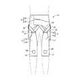
図1〜3には、本発明の実施形態としての歩行運動補助具10が示されている。歩行運動補助具10は、股関節の屈伸を補助するものであって、股関節を跨いで延びる左右一対の補助力伝達部としての補助力伝達帯12,12の両端部分に、使用者の股関節を挟んで大腿骨が位置する大腿部側に取り付けられる第1の装着部14と、使用者の股関節を挟んで寛骨が位置する腰部側に取り付けられる第2の装着部16とが、それぞれ設けられた構造を有している。そして、これら左右一対の補助力伝達帯12,12と、各第1の装着部14,14と、各第2の装着部16,16と、後述する一対の駆動源としての電動モータ40,40とで、左右一対のアシスト部材が構成されている。なお、図1〜3では、歩行運動補助具10が使用者の装着状態で図示されており、使用者の輪郭線が2点鎖線で示されている。また、以下の説明において、原則として、前面とは使用者の腹部側の面(正面)を、後面とは使用者の背部側の面(背面)を、上下とは鉛直上下方向である図1中の上下を、それぞれ言う。また、以下の説明において、「アシスト力」とは、歩行等の動作に必要とされる力を補う方向で作用する補助力のことをいい、「レジスト力」とは、動作に必要とされる力に抗する方向で作用する補助力のことを言う。 1-3, the walking
より詳細には、補助力伝達帯12は、それぞれ布地で形成された第1の牽引帯18と第2の牽引帯20を、金属製の連結金具22で連結した構造とされている。これら第1の牽引帯18および第2の牽引帯20による構成部分は、何れも柔軟に変形可能とされている。 More specifically, the auxiliary
第1の牽引帯18は、上下に延びる略帯状の布地等で形成されており、歩行運動補助具10の装着状態において使用者の大腿の前面を覆うように配設される。なお、第1の牽引帯18の材質は、変形可能な軟質の薄肉材であれば良く、触感や耐久性,通気性などを考慮して、織布や不織布の他、皮革、ゴムシート,樹脂シート等が適宜に採用され得る。特に本実施形態の第1の牽引帯18は、後述する電動モータ40による引張力の作用方向となる長さ方向(図1中、上下方向)で弾性変形可能とされていると共に、幅方向(図1中、左右方向)で弾性が小さくされて変形が制限されており、長さ方向と幅方向で入力に対する変形量の異方性を有している。なお、第1の牽引帯18は、長さ方向において、0.3kgf/cm2以上且つ0.5kgf/cm2以下の弾性を有していることが望ましい。The
また、第1の牽引帯18の上端にはリング状の連結金具22が取り付けられており、第1の牽引帯18が連結金具22を介して第2の牽引帯20に連結されている。第2の牽引帯20は、略一定の幅寸法を有する帯状であって、伸縮性の小さい繊維を用いた布地や皮革等により、ベルト状に形成されている。第2の牽引帯20は、中間部分が連結金具22に挿通されて第1の牽引帯18と連結されることにより、補助力伝達帯12が構成されている。なお、第2の牽引帯20は、必ずしも伸縮性を抑えられたものでなくても良いが、補助力の作用衝撃を緩和して装用感を向上させると共に、使用者の自己意識による運動を過度に阻害しないように、第1の牽引帯18と第2の牽引帯20の少なくとも一方は、前述の如き長さ方向の弾性変形が許容された弾性繊維等からなる伸縮性のあるものを採用することが望ましい。 Further, a ring-shaped connecting
また、補助力伝達帯12の第1の牽引帯18の下方には、第1の装着部14が一体的に設けられている。本実施形態では、第1の装着部14が、膝関節を保護するために用いられるスポーツ用サポータ状とされており、例えば伸縮性を有する布地等で形成されて使用者の膝関節に巻き付けられ、面ファスナやスナップ,フック等で装着されるようになっている。なお、第1の装着部14は、第1の牽引帯18と別体形成されて、接着や縫合などで後固着されていても良い。なお、第1の装着部14には、使用者の膝頭に位置決めされる貫通孔24が形成されることにより、膝関節の屈伸を妨げないように配慮されることが望ましい。 Further, a first mounting
また、補助力伝達帯12の第2の牽引帯20の両端部は、第2の装着部16に取り付けられている。第2の装着部16は、それぞれ腰部に装着される伝達帯支持ベルト26と駆動装置支持ベルト28を有しており、第2の牽引帯20の一方の端部が伝達帯支持ベルト26に取り付けられていると共に、他方の端部が駆動装置支持ベルト28に取り付けられている。 Further, both end portions of the
伝達帯支持ベルト26は、伸縮性の小さい帯状の布地で形成されており、使用者の腰部に巻き付けられて、両端部が面ファスナやスナップ,フック等で連結されることにより、使用者の腰部に装着される。また、伝達帯支持ベルト26には、リング状を呈する一対のガイド金具30,30が設けられており、伝達帯支持ベルト26の腰部への装着状態において、腰部の左右両側に配置される。そして、第2の牽引帯20の一方の端部が、伝達帯支持ベルト26の前面部分に対して、縫合や溶着、スナップやフック、面ファスナ等の手段を用いて取り付けられている。 The transmission
さらに、伝達帯支持ベルト26には、下方に向かって延びだすようにして、使用者の股関節における前後方向の関節角度を検出する関節角度センサとしての左右一対の静電容量型センサ32,32が取り付けられている。かかる静電容量型センサ32は、例えば特開2010−43880号公報や特開2009−20006号公報等に示されているように、弾性変形を許容された柔軟な静電容量変化型のセンサであって、図4に示されているように、誘電性の弾性材で形成された誘電体層34の両面に、導電性の弾性材で形成された一対の電極膜36a,36bを設けた構造を有している。 Further, the transmission
かかる静電容量型センサ32は、股関節を挟んだ両側に位置する腰部から大腿部に跨がって延びて、体側表面に沿って重ね合わされて広がるようにして配設されている。本実施形態では、静電容量型センサ32の上端部が、伝達帯支持ベルト26に取り付けられて支持されていると共に、静電容量型センサ32の下端部は、大腿部に巻き付けられて面ファスナ等で装着されるベルト37に対して取り付けられている。 Such a
そして、伝達帯支持ベルト26の装着状態において、静電容量型センサ32は、股関節の屈伸による作用圧力の変化を一対の電極膜36a,36bの接近/離隔に伴う静電容量の変化として検出するようになっており、かかる検出信号が後述する駆動装置38の制御装置に入力される。なお、使用者の左右の各体側表面に沿って各1つの静電容量型センサ32が重ね合わされて装着されており、寛骨に対する左大腿骨の関節における前後方向の傾斜角度(股関節の角度)と、寛骨に対する右大腿骨の関節における前後方向の傾斜角度(股関節の角度)とが、各別に検出されるようになっている。 When the transmission
かかる股関節の角度変化は、例えば静電容量型センサ32の面圧分布態様を検出することによって一層正確に検出することができる。具体的には、使用者の左右体側の各一方の表面に広がって且つ股関節を挟んだ上下に延びて配設された各静電容量型センサ32では、使用者が歩行に際して一方の脚を前方に振り出すことにより寛骨に対して大腿骨が前方に屈曲されると、静電容量型センサ32のうちで体側中央より後方に位置する領域では引張変形し且つ体側中央より前方に位置する領域では圧縮湾曲変形する。一方、脚を後方に蹴り出すと、寛骨に対して大腿骨が後方に屈曲されて、静電容量型センサ32のうちで体側中央より前方に位置する領域では引張変形し且つ体側中央より後方に位置する領域では圧縮湾曲変形する。従って、各静電容量型センサ32において、その体側中央線を挟んだ前後の何れの領域において引張変形が発生し且つ他方の領域において圧縮変形が発生しているかを、領域毎の検出値に基づいて判定し、各変形の程度に応じた検出値の大きさに基づいて股関節の角度変化量を求めることができる。 Such a change in the angle of the hip joint can be detected more accurately, for example, by detecting the surface pressure distribution mode of the
特に、本実施形態で用いられている如き静電容量型センサ32は、特開2010−43880号公報や特開2009−20006号公報等に記載のとおり薄肉で変形容易な軟質シート構造とされていることから、体表面に沿って装着しても、使用者に過度の違和感を与えたり、使用者の自発的な体動を拘束することがない。 In particular, the
一方、駆動装置支持ベルト28は、図1〜3に示されているように、伝達帯支持ベルト26と同様に、伸縮性の小さい帯状の布地等で形成されており、使用者の腰部に巻き付けられて、両端部が面ファスナやスナップ、フック等で連結されることにより、使用者の腰部に装着される。また、駆動装置支持ベルト28は、背面部分が正面部分よりも下方まで延び出して大きな面積を有しており、その背面部分に駆動装置38が装着されている。 On the other hand, as shown in FIGS. 1 to 3, the drive
駆動装置38は、図5に示されているように、駆動源としての左右一対の電動モータ40,40と、それら一対の電動モータ40,40によって回転駆動される左右一対の回転軸42,42と、電動モータ40,40に電力を供給するバッテリー等の電源装置44と、静電容量型センサ32,32の検出結果に基づいて電動モータ40,40を作動制御する制御装置46とを含んで構成されている。 As shown in FIG. 5, the
各電動モータ40は、一般的な電動機であって、好適には回転位置を検出して正逆両方向の回転量を制御することができるサーボモータ等が採用される。そして、電源装置44からの通電によって駆動される電動モータ40の駆動軸48における回転駆動力が、適宜の減速歯車列を介して、回転軸42に伝達されるようになっている。回転軸42は、周方向への回転を許容されるように支持されたロッド状の部材であって、その外周面に第2の牽引帯20の他方の端部が固定されて巻き付けられている。これにより、第2の牽引帯20の他方の端部は、駆動装置38を介して駆動装置支持ベルト28に取り付けられており、以て、補助力伝達帯12が股関節を跨いで配設されている。 Each
そして、回転軸42が電動モータ40の駆動軸48から及ぼされた駆動力によって周方向一方に回転させられることにより、補助力伝達帯12の第2の牽引帯20が回転軸42に巻き取られる。これにより、電動モータ40による駆動力が補助力伝達帯12の長さ方向(第1の牽引帯18および第2の牽引帯20の長さ方向)に伝達されて、第1の装着部14と第2の装着部16の間に引張力として及ぼされる。上記から明らかなように、補助力伝達帯12は、電動モータ40の駆動力の伝達方向に延びている。一方、回転軸42が電動モータ40によって周方向他方に回転させられると、回転軸42による補助力伝達帯12の巻き取りが解除されて送り出され、第1の装着部14と第2の装着部16の間で引張力が解除される。 The rotating
なお、電動モータ40の逆回転は必須でなく、電動モータ40への給電を停止して、補助力伝達帯12の引き出しが自由に許容され得る状態にすることにより、第1の装着部14と第2の装着部16の間での引張力を解除しても良い。これによれば、使用者の筋力による動作に伴って、補助力伝達帯12が過度に弛むことなく、動作の抵抗となる程の張力をもたないで、歩行動作に対して容易に追従することが可能になる。 The reverse rotation of the
また、電動モータ40の制御は、電源装置44から電動モータ40への通電の有無や通電方向(駆動軸48の回転方向)が制御装置46によって制御されることで実行されている。制御装置46は、静電容量型センサ32の検出結果(出力信号)に基づいて使用者の股関節の屈曲運動および伸展運動を検出して、検出した股関節の運動に応じて電動モータ40への通電を制御する。これにより、電動モータ40の駆動力に基づいて第1の装着部14と第2の装着部16の間に及ぼされる引張力が、制御装置46によって調節されている。なお、本実施形態では、制御装置46が、歩行動作の段階(例えば、股関節を屈曲して後足を前方に運ぶ段階や股関節を伸展して前足で地面を蹴る段階等の特定の股関節角度)を特定して、特定した歩行動作の段階である股関節角度に応じて電動モータ40への通電を制御するようになっている。 Further, the control of the
すなわち、制御装置46による電動モータ40,40の制御手段49は、左右の股関節の検出角度を参照信号とし、予め設定された特定段階の股関節角度に対応した電動モータ40,40の制御条件を満足するように、電源装置44から電動モータ40,40への電力供給を実行するようになっている。具体的には、例えば図6に機能ブロック図が示されているように、かかる制御手段49は、股関節角度の変化に対して電動モータ40への給電を開始/停止等するタイミングを特定する駆動タイミング情報や、電動モータ40へ給電する電力の大きさ(サポート力に対応する補助力伝達帯12の巻取り量)を特定する駆動出力情報を含む制御情報が記憶されたRAM等の記憶手段50を含んで構成されている。なお、この記憶手段50に記憶された駆動タイミング情報や、駆動出力情報は、必要に応じて変更設定可能とされて、例えば使用者毎に、サポート力を発揮する股関節の角度位置や、及ぼされるサポート力の大きさ等を調節可能とされている。 That is, the control means 49 of the
そして、制御手段49のROMやRAMに予め記憶されたプログラムに従って、制御手段49の制御部は左右の股関節の角度センサとしての静電容量型センサ32,32から出力される股関節角度を参照信号として、かかる股関節角度が、記憶手段50に予め記憶された給電の開始又は停止の股関節角度に達した場合には、記憶手段50に予め記憶された駆動出力情報に基づいて電源装置44からアシスト部材の電動モータ40への給電を開始又は停止するように駆動制御信号を出力する。また、本実施形態では、静電容量型センサ32や制御手段49における制御部、アシスト部材駆動用の電動モータ40が、何れも左右各別に独立して一対ずつ設けられており、記憶手段50における制御情報に基づいた、制御手段49による電動モータ40への給電制御が、左右の脚に対して各別に実行されるようになっている。要するに、左右一対のアシスト部材における電動モータ40,40を制御する、制御手段49による駆動制御信号が、左右の脚に対して相互に独立して出力される。 Then, according to a program stored in advance in the ROM or RAM of the control means 49, the control unit of the control means 49 uses the hip joint angles output from the
さらに、記憶手段50に記憶される駆動出力情報として、股関節角度の範囲に対応して電動モータ40へ給電する電力を変化させるための情報(巻取り量の初期値に乗算する係数など)が含まれていても良い。これにより、例えば、股関節角度が予め設定した複数段階の角度に至る毎に、電動モータ40の出力を段階的に又は次第に増大させたり減少させることが可能になり、使用者に及ぼされるアシスト力を歩行に際して一層効率化したり、使用者への違和感の更なる軽減を図ったりすることができる。 Further, the drive output information stored in the storage means 50 includes information for changing the power supplied to the
因みに、健常者の下肢筋における「大臀筋」,「大腿二頭筋」,「前脛骨筋」,「大腿直筋」,「腓腹筋」の各部位については、歩行中に発生筋力の変化を生じる。例えば、各下肢筋において、股関節の角度変化に対応して山形に経時変化する筋力発生が、歩行周期で繰り返し発生していることが知られている。従って、本実施形態の歩行運動補助具10において、股関節角度に対応したサポート力を下肢筋に及ぼすことは、あたかも人工的な筋肉を付加的に設けることとなり、下肢筋による歩行筋力を補助することが可能になるものと理解できる。 By the way, changes in the muscular strength during walking were observed for each part of the great gluteal muscle, biceps femoris, anterior tibialis muscle, rectus femoris muscle, and gastrocnemius muscle in the lower limb muscles of healthy subjects. Arise. For example, in each lower limb muscle, it is known that the generation of muscle force that changes with time in a mountain shape corresponding to the change in the angle of the hip joint repeatedly occurs in the walking cycle. Therefore, in the walking
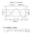
また、健常者の歩行に際して、前述の如き静電容量型センサ32の出力値に基づいて股関節の角度変化を検出したところ、図7に示されているように、周期的な股関節の変化パターンを実用的な精度をもって検出することが確認できた。それ故、かかる静電容量型センサ32の検出信号に基づいて、予め特定された所定のタイミングで電動モータ40への給電の開始や停止等を制御することにより、上述の如き歩行筋力の補助効果が発揮されるものと考えられる。なお、歩行に際しての股関節の角度変化幅や、股関節の位相と各筋肉の発生筋力との相対関係は、使用者個人の体格や歩き方、癖などによって異なることから、例えば図7中のアシストA,B,Cとして示された何れのポイントで電動モータ40への給電の開始や停止等を実行するかという具体的設定は、使用者毎に変更設定されることが望ましい。その際、かかる設定ポイントが使用者に適合しているか否かの判定は、使用者の主観的意見を参照して行う他、例えば電動モータ40への給電の開始や停止等のポイントを変更してそれぞれ実測した使用者の筋電位センサの出力値を相対比較して得られたサポート効果の適否判定結果などに基づいて行うことも可能である。 Further, when a healthy person walks, the angle change of the hip joint is detected based on the output value of the
ところで、図8にモデル的に示されているように、補助力伝達帯12の上端部分の使用者に対する装着位置を支点Aとし、使用者における股関節位置を支点Bとし補助力伝達帯12の下端部分の使用者に対する装着位置を支点Cとすると、補助力伝達帯12の長さに相当する△ABCにおける辺ACの長さは、股関節の角度θに応じて変化する。なお、図8中の点Oは、支点Aを通る水平線と支点Bを通る鉛直線との交点である。また、支点Aの位置は、第2の牽引帯20の一方の端部における伝達帯支持ベルト26への取付位置と該第2の牽引帯20が挿通されたガイド金具30との略中間位置となる。 By the way, as modelly shown in FIG. 8, the mounting position of the upper end portion of the auxiliary
ここにおいて、かかる有効長としての補助力伝達帯12の長さ(辺ACの長さ)は、図9に示されているように、歩行に際しての股関節の角度に応じて周期的に変化することとなり、その具体的な長さは、図9中の数式によって求めることができる。そして、本実施形態では、かかる数式に基づいて算出される辺ACと、辺ACの撓みのない基準長さとの差分に相当する寸法だけ補助力伝達帯12の長さが変化するように、電動モータ40を正逆回転制御することにより、歩行中に補助力伝達帯12に作用する張力が略一定(例えば略±0)に維持されて撓みが防止されるようになっている。 Here, as shown in FIG. 9, the length of the auxiliary
このような補助力伝達帯12の張力調節による撓み防止制御は、歩行時の股関節角度θに応じて、予め記憶された関係式に基づいて電動モータ40を回転作動させて、第2の牽引帯20の巻き取り量と送り出し量を調節することによって実現される。具体的には、例えば図6に機能ブロック図が示されているように、かかる撓み防止制御系は、股関節の角度の変化に対して補助力伝達帯12の長さ(辺ACの長さ)を算出する上述の数式の係数、補助力伝達帯12の基準長、および第2の牽引帯20の巻き取り/送り出し量に対応する電動モータ40の回転方向ならびに給電を開始/停止するタイミングを特定する駆動タイミング情報を含む撓み防止制御情報が記憶されたRAM等の記憶手段50を含んで構成されている。なお、この記憶手段50に記憶された駆動タイミング情報は、必要に応じて変更設定可能とされて、例えば使用者毎の体格に合わせて調節可能とされている。そして、かかる撓み防止制御は、図10に示されているように、前述の股関節の角度に対応したサポート力の制御とは独立して行うことが可能であり、両方の制御を重ね合わせて両方の制御の目標値が重ね合わされて達成されるように電動モータ40を作動制御することができる。これにより、撓み防止制御によって補助力伝達帯12が略一定の展張状態に維持されることから、サポート力の制御に基づいて電動モータ40を作動させた際に、股関節の角度変化に対応した補助力伝達帯12の長さ変化による悪影響を殆ど受けることなく、目的とするサポート力を使用者の脚部に安定して精度良く与えることが可能になる。 Such bending prevention control by adjusting the tension of the auxiliary
かくの如き構造とされた歩行運動補助具10を装用すれば、股関節を屈曲する際に、股関節の屈曲運動に必要な力を補強するように補助力(アシスト力)を及ぼして、股関節の屈伸を伴う動作が補助することが可能となる。即ち、制御装置46は、静電容量型センサ32の検出結果に基づいて使用者が股関節を屈曲しようとしていることを特定すると、電源装置44から電動モータ40に通電して回転軸42を周方向一方に回転させる。これにより、第2の牽引帯20が回転軸42によって巻き取られて、第2の牽引帯20の実質的な長さが短くなることから、第2の牽引帯20の中間部分に外挿された連結金具22が第2の装着部16側(上側)に引き寄せられて変位させられることで、補助力伝達帯12の長さが短くなる。そして、連結金具22に取り付けられた第1の牽引帯18を通じて第1の装着部14に引張力が及ぼされて、膝関節に装着された第1の装着部14が腰部に装着された第2の装着部16側に引き寄せられる。その結果、膝関節を重力に抗して腰部側に引き付けるようにアシスト力が作用して、股関節の屈曲を伴う歩行運動を行う筋力が補助される。なお、静電容量型センサ32で検出される股関節角度θの値の変化に応じて、制御装置46で回転軸42の回転力(電動モータ40への給電圧)を調節すれば、使用者が行おうとする動作に対して過不足のないアシスト力を一層効率的に提供することが可能になる。また、股関節角度θの値が予め設定された値に達したら、電動モータ40への通電が停止されることにより、股関節の運動を過度に補足したり拘束することによる使用者の違和感が回避される。 If the walking
一方、制御装置46は、静電容量型センサ32の検出結果に基づいて使用者が股関節を伸展させようとしていることを特定すると、電源装置44から電動モータ40に通電して回転軸42を周方向他方に回転させる。これにより、回転軸42から第2の牽引帯20が送り出されて、第2の牽引帯20の実質的な長さが長くなることから、第2の牽引帯20の中間部分に外挿された連結金具22が自重や弾性等によって第2の装着部16から離隔する方向(下側)に変位する。そして、連結金具22に取り付けられた第1の牽引帯18を通じて第1の装着部14に及ぼされていた引張力が解除されることにより、股関節の伸展運動が歩行運動補助具10によって妨げられるのが防止される。 On the other hand, when the
このように、歩行運動補助具10を装用すれば、股関節を屈曲する際に必要とされる力の一部が電動モータ40の発生力によって補われることから、例えば、歩行時に股関節を屈曲して後足を前方に運ぶ動作をする際に、小さな筋力で目的とする動作を行うことが可能とされる。従って、歩行運動補助具10を用いれば、加齢や傷病によって使用者が動作を行うための充分な筋力を備えていない場合にも、目的とする動作をスムーズに行うことができて、使用者の活動が制限されるのを防ぐことが可能となる。 As described above, if the walking
また、電動モータ40の発生駆動力をアシスト力として使用者の脚部に伝達する経路上に設けられた補助力伝達帯12の第1の牽引帯18は、力の伝達方向で弾性変形可能とされている。これにより、電動モータ40の発生駆動力は、第1の牽引帯18の弾性変形によって緩和されてから、使用者の脚部に及ぼされる。それ故、電動モータ40の発生駆動力がダイレクトに伝達される場合に比して、使用者の関節等への負荷が軽減されて、筋を痛める等といった問題が生じるのを防ぐことができる。特に本実施形態では、使用者の脚部に及ぼされるアシスト力が2kgf〜5kgf程度の比較的に小さな力とされることが望ましい。これにより、使用者に対して強制的に動作をさせるのではなく、あくまでも動作に必要な筋力の不足を補うという思想に基づくサポート力の作用が実現されて、使用者の身体に負担をかけることなく、必要な補助を行うことが可能となる。 In addition, the
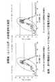
因みに、本実施形態に従う構造とされた歩行運動補助具10を実際に健常者に装着して、歩行に際してのサポート効果を確認する実験を行った。かかる実験に際しては、腓腹筋の表面に筋電位センサを装着して、サポート力を及ぼしてアシスト有りの場合と、サポート力を及ぼさないアシスト無しの場合とにおいて、筋電位の検出波形を比較した。その結果を、図11に示す。なお、サポート力の作用開始のタイミングは、股関節角度θを参照信号として、前述の図7におけるB点とC点を設定した場合についてそれぞれ実験した。図12に示されているように、サポート力を及ぼすことにより、歩行周期の20〜40%の領域において筋電位が減少して有効なサポート効果が発揮されていることを確認できた。 Incidentally, an experiment was performed in which a walking
さらに、補助力伝達帯12が軟質で変形可能とされていることから、従来の外骨格式の補助力伝達装置のように使用者に対して過度な拘束感を及ぼすことがなく、特に横方向から押されたりした際の外乱入力に際しても、使用者の自発的且つ瞬発的な動作が許容されることにより、転倒回避作動が実現され得る。 Further, since the auxiliary
なお、サポート力の衝撃的作用を回避すると共に、使用者への拘束軽減の目的から、第1の牽引帯18の力の伝達方向での弾性は、0.3kgf/cm2〜0.5kgf/cm2の間に設定されることが望ましい。これにより、電動モータ40の発生駆動力が充分に緩衝されて、使用者の脚部に過大な負荷が作用するのを回避できると共に、使用者の自発的な動作を充分に許容し得るだけの有効なアシスト力が使用者の脚部に伝達されて、動作を効果的に補助することができる。Note that the elasticity of the
さらに、第1の牽引帯18は、力の伝達方向と略直交する方向での変形が制限されており、第1の牽引帯18と一体形成された第1の装着部14の周方向での伸縮(拡径変形乃至は縮径変形)が抑えられて、形状の安定性が高められている。これにより、電動モータ40による引張力の作用時に、第1の装着部14が膝関節から外れることなく保持されて、アシスト力が脚部に対して有効に伝達される。 Further, the
また、歩行運動補助具10によるアシスト力は、股関節の屈曲運動に際して発揮される一方で、股関節の伸展運動に際して解除される。これにより、歩行運動補助具10を装用すれば、起立状態において重力に抗した運動が必要とされる股関節の屈曲運動が補助される一方、起立状態において重力の作用で補助される股関節の伸展運動では、アシスト力が抗力として作用してしまうことが回避されて、スムーズな動作が実現される。従って、股関節の屈曲と伸展を繰り返し行う歩行動作等においても、動作の妨げとなることなく、必要なアシスト力を適時に提供して動作を適切に補助することができる。 Further, the assisting force by the walking
本実施形態の歩行運動補助具10において、このような使用者の動作状態に応じたアシスト力の発生が、静電容量型センサ32による股関節角度の検出結果に基づいて、記憶手段50に記憶された制御用信号を参照しつつ制御装置46が自動的に実行するようになっていることから、使用者における面倒な操作も不要となる。また、本実施形態では、左右の脚部筋力に対するサポート力の制御が、左右の股関節角度に基づいて各別に独立して実行されることから、例えば何かにつまづく等して一方の脚の股関節角度だけが大きく変化した場合などにおいても、かかる一方の足の股関節角度の検出値に基づく大きなサポート力を発揮させる等といった制御も容易に実現可能となる。 In the walking
しかも、本実施形態では静電容量型センサ32が採用されていることから、温度変化に対する検出精度の低下が小さいと共に、温度変化に対する補正も容易であることから、例えば歩行運動に伴う使用者の体温変化等に起因して温度変化が大きい場合にも正しい検出結果を安定して得ることができる。加えて、静電容量型センサ32では、繰返しの入力に対する検出精度の低下が小さいことから、充分な耐久性を確保することができて、日常生活での常用等が高精度に実現可能となる。 In addition, since the
また、本実施形態における補助力伝達部が、帯形状を有する肉薄の布で形成された補助力伝達帯12とされていることにより、充分な柔軟性が付与されており、硬質の外骨格を有する歩行運動補助具に比して、容易に着脱することができる。即ち、硬質の外骨格を使用者に装着する場合、使用者は外骨格の形状に合わせて関節の曲げ角度を調節する必要があるし、着座して装着することは難しい場合も多い。しかし、本実施形態の歩行運動補助具10は、第1の装着部14と第2の装着部16を連結する補助力伝達帯12が柔軟で必要に応じて撓むことから、補助力伝達帯12を充分に長くしておけば、使用者の関節の曲げ角度がどの程度であったとしても、第1の装着部14と第2の装着部16をそれぞれ適切な位置に取り付けることが可能である。しかも、補助力伝達帯12が柔軟であることによって、例えば、股関節を屈曲した着座姿勢で第1の装着部14と第2の装着部16をそれぞれ装着することが可能とされており、楽な姿勢で着脱作業を行うことができる。 In addition, since the auxiliary force transmission portion in the present embodiment is the auxiliary
さらに、肉薄帯形状の布で形成された補助力伝達帯12を採用することにより、歩行運動補助具10が軽量とされて、筋力の低下した高齢者等でも容易に取り扱うことができる。しかも、本実施形態では、第1の装着部14および第2の装着部16もそれぞれ布製とされていることから、歩行運動補助具10全体がより軽量化とされており、着脱作業等を含む取回し性の更なる向上が図られている。 Furthermore, by adopting the auxiliary
更にまた、補助力伝達帯12が肉薄の布製とされていることにより、装着状態において補助力伝達帯12が使用者の体表面の形状に沿って配設されると共に、体表面に沿って厚さ方向で容易に湾曲する。それ故、歩行運動補助具10の上に衣服を重ねて着用することも可能となり、日常生活において目立つことなく気軽に使用することができる。 Furthermore, since the auxiliary
また、第1の装着部14が膝関節に取り付けられると共に、第2の装着部16が腰部に取り付けられることにより、補助力伝達帯12の長さが必要以上に長くなるのを防いで歩行運動補助具10の小型化を図りつつ、アシスト力が脚部に対して効率的に及ぼされる。蓋し、大腿の揺動時に支点となる股関節から作用点となる第1及び第2の装着部14,16までの離隔距離が大きくされると、引張力によるサポート力が脚部に対して効率的に作用するからである。しかも、駆動装置38が歩行時に運動量の少ない腰部に設けられていることにより、駆動装置38が歩行動作の妨げになるのを軽減できる。 In addition, the first mounting
以上、本発明の実施形態について詳述してきたが、本発明はその具体的な記載によって限定されない。例えば、第1の装着部は、膝関節よりも上方の大腿部に装着することも可能であり、それによって装置のコンパクト化が実現可能となる。 As mentioned above, although embodiment of this invention was explained in full detail, this invention is not limited by the specific description. For example, the first attachment portion can be attached to the thigh above the knee joint, thereby realizing a compact device.
また、制御装置や電源装置等の装着位置は限定されるものでなく、例えば通電用リード線によって接続された独立構造として使用者の衣服のポケットに収容したり、使用者の肩にかけたり等して装着することも可能である。 In addition, the mounting position of the control device, the power supply device, etc. is not limited. For example, the control device or the power supply device is housed in the user's clothes pocket as an independent structure connected by an energizing lead wire or hung on the user's shoulder. It is also possible to wear it.
さらに、使用者の動作を検出する関節角度センサとしては、静電容量型のセンサに限定されるものではなく、例えば、力の作用による抵抗値の変化に基づいて使用者の動作を検出する抵抗変化型のセンサを採用することも可能である。このような抵抗変化型のセンサを採用すれば、直流電圧を用いての計測が可能であることから、計測回路の簡易化が容易であり、小型化やコストの低減を実現し易くなる。しかも、小さな力の作用に対しても抵抗値が鋭敏に変化することから、関節の僅かな運動から大きな運動まで幅広く検出することが可能となる。なお、抵抗変化型センサとしては、例えば、特開2008−69313号公報等に示された柔軟性を有するものが好適に採用される。また、静電容量型センサと抵抗変化型センサを組み合わせて用いる等、構造や検出方法の異なる複数種類のセンサを組み合わせて用いても良い。 Further, the joint angle sensor that detects the user's movement is not limited to the capacitance type sensor, and for example, a resistance that detects the movement of the user based on a change in the resistance value due to the action of force. It is also possible to employ a change type sensor. If such a resistance change type sensor is employed, measurement using a DC voltage is possible. Therefore, the measurement circuit can be easily simplified, and downsizing and cost reduction can be easily realized. In addition, since the resistance value changes sharply even with the action of a small force, it is possible to detect a wide range from a slight motion to a large motion of the joint. As the resistance change type sensor, for example, a flexible sensor as disclosed in JP 2008-69313 A is suitably employed. Also, a plurality of types of sensors having different structures and detection methods may be used in combination, such as a combination of a capacitance type sensor and a resistance change type sensor.
また、例えば、図12に示されているように、静電容量型センサ54を第1の牽引帯18の裏面(大腿への重ね合わせ面)に装着して大腿前面に重ね合わせて装着することにより、股関節を屈曲する際の大腿筋の変形に伴う第1の牽引帯18と大腿の間での挟圧力を静電容量の変化として検出することもできる。或いは、例えば、図13に示されているように、使用者の臀部から大腿にかけて広がる静電容量型センサ56を採用すれば、股関節の屈伸をより直接的に検出することができる。この場合、歩行運動補助具57は、補助力伝達帯12および第1,第2の装着部14,16に加えて、静電容量型センサ56を備えたパンツ(レギンス)状のセンサ保持スーツ58を含んで構成されており、センサ保持スーツ58を装着してから、補助力伝達帯12および第1,第2の装着部14,16を装着する。なお、図12,図13に示された静電容量型センサ54,56も、基本的な構造は実施形態に示された静電容量型センサ32と同じものが採用可能である。また、図12,図13に示されている如き大腿部の前面に装着される静電容量型センサ54や、臀部の表面に装着される静電容量型センサ56を、その上下両端部分で使用者の体表面に取り付けて、例えば足を踏み出した際に引張り変形されると共に、足を蹴り出した際には引張変形が緩和されることに伴う応力変化を利用して、股関節の前後方向の揺動角を検出することも可能である。さらに、関節角度センサとして、ロータリーエンコーダ等の角度を直接に検出するセンサを採用して、股関節角度を直接に検出することも可能である。 Also, for example, as shown in FIG. 12, the
また、補助力伝達部は、必ずしも全体が可撓性(柔軟性)を有するものに限定されず、部分的であれば金属や合成樹脂等で形成された硬質な部分があっても良い。更に、補助力伝達部の全体が力の伝達方向で弾性変形可能とされていても良いし、補助力伝達部が力の伝達方向での弾性変形を部分的に許容されていても良い。 In addition, the auxiliary force transmission portion is not necessarily limited to a portion having flexibility (flexibility) as a whole, and may be a hard portion formed of metal, synthetic resin, or the like as long as it is partial. Further, the entire auxiliary force transmission unit may be elastically deformable in the force transmission direction, or the auxiliary force transmission unit may be partially allowed to elastically deform in the force transmission direction.
10,57:歩行運動補助具、12:補助力伝達帯(補助力伝達部)、14:第1の装着部、16:第2の装着部、32,54,56:静電容量型センサ、40:電動モータ(駆動源)、46:制御装置、49:制御手段、50:記憶手段10, 57: Walking exercise assisting device, 12: Auxiliary force transmission band (assisting force transmission unit), 14: First mounting unit, 16: Second mounting unit, 32, 54, 56: Capacitive sensor, 40: electric motor (drive source), 46: control device, 49: control means, 50: storage means
Claims (6)
Translated fromJapanese該使用者の股関節における前後方向の関節角度を検出する関節角度センサと、
該使用者の股関節における関節角度の変化に対応して前記各アシスト部材における前記各駆動源を駆動するための駆動タイミング情報および駆動出力情報に関する制御情報を記憶する記憶手段と、
該記憶手段における該制御情報に基づいて前記左右一対のアシスト部材における前記各駆動源をそれぞれ駆動制御する制御手段と
を、有することを特徴とする歩行運動補助具。A first mounting portion to be mounted on the thigh side sandwiching the user's hip joint and a second mounting portion to be mounted on the waist portion are provided on both ends of the flexible auxiliary force transmission portion. While being provided with a pair of left and right assist members provided with a drive source that exerts a tensile force on the auxiliary force transmission unit,
A joint angle sensor for detecting a joint angle in the front-rear direction of the hip joint of the user;
Storage means for storing control information related to drive timing information and drive output information for driving each drive source in each assist member in response to a change in joint angle at the hip joint of the user;
A walking exercise assisting device comprising: control means for driving and controlling the drive sources of the pair of left and right assist members based on the control information in the storage means.
前記制御手段は、該記憶手段に記憶されている該撓み防止制御情報に基づいて該関節角度の変化に対応して変更せしめて、該補助力伝達部を一定の張力作用状態に保つように前記左右一対のアシスト部材における前記各駆動源をそれぞれ駆動制御する請求項1〜3の何れか1項に記載の歩行運動補助具。The storage means stores flexure prevention control information for following the effective length of the auxiliary force transmission unit in the assist member in response to a change in joint angle at the hip joint of the user,
The control means changes the joint angle according to the change in the joint angle based on the deflection prevention control information stored in the storage means, and keeps the auxiliary force transmission portion in a constant tension acting state. The walking exercise assisting device according to any one of claims 1 to 3, wherein each of the drive sources in the pair of left and right assist members is driven and controlled.
Priority Applications (5)
| Application Number | Priority Date | Filing Date | Title |
|---|---|---|---|
| JP2012082388AJP5876358B2 (en) | 2012-03-30 | 2012-03-30 | Walking exercise aid |
| PCT/JP2013/002156WO2013145769A1 (en) | 2012-03-30 | 2013-03-29 | Ambulatory movement assistance device |
| EP13770071.2AEP2832338B1 (en) | 2012-03-30 | 2013-03-29 | Walking movement aid |
| CN201380005666.XACN104053424B (en) | 2012-03-30 | 2013-03-29 | Walking movement auxiliary implement |
| US14/305,445US9763847B2 (en) | 2012-03-30 | 2014-06-16 | Walking movement aid |
Applications Claiming Priority (1)
| Application Number | Priority Date | Filing Date | Title |
|---|---|---|---|
| JP2012082388AJP5876358B2 (en) | 2012-03-30 | 2012-03-30 | Walking exercise aid |
Publications (2)
| Publication Number | Publication Date |
|---|---|
| JP2013208397Atrue JP2013208397A (en) | 2013-10-10 |
| JP5876358B2 JP5876358B2 (en) | 2016-03-02 |
Family
ID=49259062
Family Applications (1)
| Application Number | Title | Priority Date | Filing Date |
|---|---|---|---|
| JP2012082388AExpired - Fee RelatedJP5876358B2 (en) | 2012-03-30 | 2012-03-30 | Walking exercise aid |
Country Status (5)
| Country | Link |
|---|---|
| US (1) | US9763847B2 (en) |
| EP (1) | EP2832338B1 (en) |
| JP (1) | JP5876358B2 (en) |
| CN (1) | CN104053424B (en) |
| WO (1) | WO2013145769A1 (en) |
Cited By (10)
| Publication number | Priority date | Publication date | Assignee | Title |
|---|---|---|---|---|
| CN105992554A (en)* | 2013-12-09 | 2016-10-05 | 哈佛大学校长及研究员协会 | Assistive flexible suits, flexible suit systems, and methods of manufacture and control thereof for assisting human mobility |
| JP2017104194A (en)* | 2015-12-07 | 2017-06-15 | パナソニック株式会社 | Operation support apparatus and method for controlling operation support apparatus |
| KR101899553B1 (en) | 2018-04-23 | 2018-09-17 | 김기연 | Walking assistance device for pets |
| US10843332B2 (en) | 2013-05-31 | 2020-11-24 | President And Fellow Of Harvard College | Soft exosuit for assistance with human motion |
| US10864100B2 (en) | 2014-04-10 | 2020-12-15 | President And Fellows Of Harvard College | Orthopedic device including protruding members |
| KR20210053677A (en)* | 2019-11-04 | 2021-05-12 | 연세대학교 원주산학협력단 | Wearable apparatus for assist child walk |
| US11014804B2 (en) | 2017-03-14 | 2021-05-25 | President And Fellows Of Harvard College | Systems and methods for fabricating 3D soft microstructures |
| US11464700B2 (en) | 2012-09-17 | 2022-10-11 | President And Fellows Of Harvard College | Soft exosuit for assistance with human motion |
| US11498203B2 (en) | 2016-07-22 | 2022-11-15 | President And Fellows Of Harvard College | Controls optimization for wearable systems |
| US11590046B2 (en) | 2016-03-13 | 2023-02-28 | President And Fellows Of Harvard College | Flexible members for anchoring to the body |
Families Citing this family (38)
| Publication number | Priority date | Publication date | Assignee | Title |
|---|---|---|---|---|
| US9656117B2 (en) | 2009-06-19 | 2017-05-23 | Tau Orthopedics, Llc | Wearable resistance garment with power measurement |
| US10124205B2 (en) | 2016-03-14 | 2018-11-13 | Tau Orthopedics, Llc | Toning garment with modular resistance unit docking platforms |
| US10004937B2 (en) | 2009-06-19 | 2018-06-26 | Tau Orthopedics Llc | Wearable modular resistance unit |
| US8986177B2 (en) | 2009-06-19 | 2015-03-24 | Tau Orthopedics, Llc | Low profile passive exercise garment |
| JP5876358B2 (en) | 2012-03-30 | 2016-03-02 | 国立大学法人九州大学 | Walking exercise aid |
| KR20150094427A (en)* | 2014-02-11 | 2015-08-19 | 삼성전자주식회사 | Wearable robot and method for controlling the same |
| KR102250260B1 (en)* | 2014-07-17 | 2021-05-10 | 삼성전자주식회사 | A connecting module and a motion assist apparatus comprising thereof |
| JP5876550B1 (en)* | 2014-08-28 | 2016-03-02 | 国立大学法人九州大学 | Joint motion assist device |
| US9772684B2 (en)* | 2014-09-17 | 2017-09-26 | Samsung Electronics Co., Ltd. | Electronic system with wearable interface mechanism and method of operation thereof |
| AU2016208973A1 (en)* | 2015-01-19 | 2017-08-31 | Jim Li | An orthotic for muscle imbalance and posture correction and lumbopelvic support |
| DE102015101329A1 (en) | 2015-01-29 | 2016-08-04 | Airbus Operations Gmbh | Support device for stabilizing a body part of a person |
| WO2016154287A1 (en)* | 2015-03-23 | 2016-09-29 | Tau Orthopedics, Llc | Toning garment with modular resistance unit docking platforms |
| US10561881B2 (en) | 2015-03-23 | 2020-02-18 | Tau Orthopedics, Inc. | Dynamic proprioception |
| KR102541908B1 (en) | 2015-07-21 | 2023-06-09 | 삼성전자주식회사 | A frame module and a motion assist apparatus comprising thereof |
| KR102429612B1 (en) | 2015-07-27 | 2022-08-05 | 삼성전자주식회사 | Method for walking assist, and devices operating the same |
| US20170274249A1 (en)* | 2016-03-23 | 2017-09-28 | Tau Orthopedics, Llc | Wearable resistance device with power monitoring |
| KR102646609B1 (en) | 2016-09-07 | 2024-03-12 | 삼성전자주식회사 | A wearing module and a motion assist apparatus comprising thereof |
| JP6832530B2 (en)* | 2016-09-30 | 2021-02-24 | パナソニックIpマネジメント株式会社 | Assist system, assist method and computer program |
| JP6851021B2 (en)* | 2016-10-05 | 2021-03-31 | パナソニックIpマネジメント株式会社 | Assist device, assist method and program |
| KR102503955B1 (en) | 2016-11-02 | 2023-02-28 | 삼성전자주식회사 | Method and apparatus for controlling balance |
| KR102655665B1 (en) | 2016-12-28 | 2024-04-09 | 삼성전자주식회사 | Apparatus for gait assistance and operating method thereof |
| FR3063008B1 (en) | 2017-02-21 | 2022-03-18 | Marc Bardgett | WALKING AID WHEELCHAIR |
| US10959634B2 (en)* | 2017-05-02 | 2021-03-30 | Nanowear Inc. | Wearable congestive heart failure management system |
| JP6941817B2 (en)* | 2017-07-10 | 2021-09-29 | パナソニックIpマネジメント株式会社 | Assist device and how to operate the assist device |
| JP7054801B2 (en)* | 2017-07-18 | 2022-04-15 | パナソニックIpマネジメント株式会社 | Assist device and assist method |
| JP7065369B2 (en)* | 2017-10-13 | 2022-05-12 | パナソニックIpマネジメント株式会社 | Assist device, operation method and program of assist device |
| JP7174919B2 (en)* | 2017-10-27 | 2022-11-18 | パナソニックIpマネジメント株式会社 | Assist device, operating method and program for assist device |
| JP7142252B2 (en)* | 2017-10-31 | 2022-09-27 | パナソニックIpマネジメント株式会社 | Assist device, operating method and program for assist device |
| JP7228830B2 (en)* | 2017-10-31 | 2023-02-27 | パナソニックIpマネジメント株式会社 | Assist device, operating method and program for assist device |
| JP7142253B2 (en)* | 2017-10-31 | 2022-09-27 | パナソニックIpマネジメント株式会社 | Assist device, operating method and program for assist device |
| JP7142254B2 (en)* | 2017-10-31 | 2022-09-27 | パナソニックIpマネジメント株式会社 | Assist device, operating method and program for assist device |
| EP3727271B1 (en)* | 2017-12-21 | 2023-09-20 | Scuola Superiore di Studi Universitari e di Perfezionamento Sant'Anna | Wearable robot with perfected control architecture |
| WO2019245633A1 (en)* | 2018-06-18 | 2019-12-26 | Moveo Walks, Inc. | Systems and devices for assistive mobility |
| CN110652423B (en)* | 2019-10-12 | 2021-11-12 | 东南大学 | Wearable upper limb rehabilitation training robot with accurate force control |
| WO2021116721A1 (en) | 2019-12-11 | 2021-06-17 | Palmai Balint | Motion assistance device |
| CN111317972B (en)* | 2020-03-20 | 2021-11-12 | 南京林业大学 | Training device for health preserving and rehabilitation and use method thereof |
| CN111568703A (en)* | 2020-05-18 | 2020-08-25 | 大连交通大学 | Flexible lower limb exoskeleton robot and bionic control method |
| CN114393568A (en)* | 2022-02-16 | 2022-04-26 | 广州海同工业技术有限公司 | A flexible exoskeleton for working at heights |
Citations (4)
| Publication number | Priority date | Publication date | Assignee | Title |
|---|---|---|---|---|
| JP4200492B2 (en)* | 2004-03-11 | 2008-12-24 | 国立大学法人 筑波大学 | Wearable motion assist device |
| JP2010042069A (en)* | 2008-08-08 | 2010-02-25 | Honda Motor Co Ltd | Control device and control method of walking aid device |
| JP2010075668A (en)* | 2008-09-23 | 2010-04-08 | Universal Entertainment Corp | Device for attaching reel band to reel wheel of rotary reel for slot game |
| JP2010110464A (en)* | 2008-11-06 | 2010-05-20 | Honda Motor Co Ltd | Walking aid device |
Family Cites Families (21)
| Publication number | Priority date | Publication date | Assignee | Title |
|---|---|---|---|---|
| JP2894778B2 (en)* | 1990-03-05 | 1999-05-24 | アルケア株式会社 | Supporter |
| JP4611580B2 (en)* | 2001-06-27 | 2011-01-12 | 本田技研工業株式会社 | Torque application system |
| JP4424269B2 (en)* | 2005-06-24 | 2010-03-03 | カシオ計算機株式会社 | Muscle strength control device |
| US8083644B2 (en)* | 2005-12-14 | 2011-12-27 | Peter Purdy | Resistance garments and active materials |
| JP5166714B2 (en) | 2006-09-15 | 2013-03-21 | 東海ゴム工業株式会社 | Cross-linked elastomer for sensor and method for producing the same |
| JP5496446B2 (en) | 2007-07-12 | 2014-05-21 | 東海ゴム工業株式会社 | Capacitive sensor |
| JP4271711B2 (en)* | 2007-10-02 | 2009-06-03 | 本田技研工業株式会社 | Exercise assistance device |
| JP4271712B2 (en)* | 2007-10-15 | 2009-06-03 | 本田技研工業株式会社 | Exercise assistance device |
| US20120095379A1 (en)* | 2008-05-28 | 2012-04-19 | Hiroshima University | Pelvic belt |
| AU2009273927B2 (en)* | 2008-07-23 | 2014-09-18 | Ekso Bionics, Inc. | An exoskeleton and method of reducing the energy consumption of a person in motion coupled to an exoskeleton device |
| JP4650538B2 (en) | 2008-08-08 | 2011-03-16 | 東海ゴム工業株式会社 | Capacitive sensor |
| US7958789B2 (en) | 2008-08-08 | 2011-06-14 | Tokai Rubber Industries, Ltd. | Capacitive sensor |
| JP5101470B2 (en)* | 2008-08-25 | 2012-12-19 | 本田技研工業株式会社 | Assist device |
| CN101518472B (en)* | 2009-03-24 | 2011-02-02 | 中国人民解放军海军航空工程学院 | Intelligent exoskeleton carrying system for lower limb and control method thereof |
| US9314394B2 (en)* | 2009-10-21 | 2016-04-19 | Honda Motor Co., Ltd. | Motion assisting device, control method therefor, and rehabilitation method |
| KR101146112B1 (en)* | 2010-03-15 | 2012-05-16 | 한국산재의료원 | Power-driven walking supporting device |
| JP5505631B2 (en)* | 2010-04-28 | 2014-05-28 | 国立大学法人北海道大学 | Lumbar strength aids |
| CN201840552U (en)* | 2010-10-09 | 2011-05-25 | 刘勤 | Linear-electric-cylinder-driving assistor for walking of human body exoskeleton |
| CN102078228A (en)* | 2010-12-30 | 2011-06-01 | 霍启英 | Intelligent mechanical leg |
| JP5876358B2 (en) | 2012-03-30 | 2016-03-02 | 国立大学法人九州大学 | Walking exercise aid |
| US9351900B2 (en) | 2012-09-17 | 2016-05-31 | President And Fellows Of Harvard College | Soft exosuit for assistance with human motion |
- 2012
- 2012-03-30JPJP2012082388Apatent/JP5876358B2/ennot_activeExpired - Fee Related
- 2013
- 2013-03-29WOPCT/JP2013/002156patent/WO2013145769A1/enactiveApplication Filing
- 2013-03-29EPEP13770071.2Apatent/EP2832338B1/enactiveActive
- 2013-03-29CNCN201380005666.XApatent/CN104053424B/ennot_activeExpired - Fee Related
- 2014
- 2014-06-16USUS14/305,445patent/US9763847B2/enactiveActive
Patent Citations (4)
| Publication number | Priority date | Publication date | Assignee | Title |
|---|---|---|---|---|
| JP4200492B2 (en)* | 2004-03-11 | 2008-12-24 | 国立大学法人 筑波大学 | Wearable motion assist device |
| JP2010042069A (en)* | 2008-08-08 | 2010-02-25 | Honda Motor Co Ltd | Control device and control method of walking aid device |
| JP2010075668A (en)* | 2008-09-23 | 2010-04-08 | Universal Entertainment Corp | Device for attaching reel band to reel wheel of rotary reel for slot game |
| JP2010110464A (en)* | 2008-11-06 | 2010-05-20 | Honda Motor Co Ltd | Walking aid device |
Cited By (14)
| Publication number | Priority date | Publication date | Assignee | Title |
|---|---|---|---|---|
| US11464700B2 (en) | 2012-09-17 | 2022-10-11 | President And Fellows Of Harvard College | Soft exosuit for assistance with human motion |
| US10843332B2 (en) | 2013-05-31 | 2020-11-24 | President And Fellow Of Harvard College | Soft exosuit for assistance with human motion |
| JP2016539723A (en)* | 2013-12-09 | 2016-12-22 | プレジデント アンド フェローズ オブ ハーバード カレッジ | Auxiliary flexible suit, flexible suit system, and method for making and controlling it to aid human mobility |
| CN105992554A (en)* | 2013-12-09 | 2016-10-05 | 哈佛大学校长及研究员协会 | Assistive flexible suits, flexible suit systems, and methods of manufacture and control thereof for assisting human mobility |
| US11324655B2 (en) | 2013-12-09 | 2022-05-10 | Trustees Of Boston University | Assistive flexible suits, flexible suit systems, and methods for making and control thereof to assist human mobility |
| CN115089444A (en)* | 2013-12-09 | 2022-09-23 | 哈佛大学校长及研究员协会 | Ways to Promote Gait Improvement |
| US10864100B2 (en) | 2014-04-10 | 2020-12-15 | President And Fellows Of Harvard College | Orthopedic device including protruding members |
| JP2017104194A (en)* | 2015-12-07 | 2017-06-15 | パナソニック株式会社 | Operation support apparatus and method for controlling operation support apparatus |
| US11590046B2 (en) | 2016-03-13 | 2023-02-28 | President And Fellows Of Harvard College | Flexible members for anchoring to the body |
| US11498203B2 (en) | 2016-07-22 | 2022-11-15 | President And Fellows Of Harvard College | Controls optimization for wearable systems |
| US11014804B2 (en) | 2017-03-14 | 2021-05-25 | President And Fellows Of Harvard College | Systems and methods for fabricating 3D soft microstructures |
| KR101899553B1 (en) | 2018-04-23 | 2018-09-17 | 김기연 | Walking assistance device for pets |
| KR102307570B1 (en) | 2019-11-04 | 2021-09-30 | 연세대학교 원주산학협력단 | Wearable gait rehabilitation device for children |
| KR20210053677A (en)* | 2019-11-04 | 2021-05-12 | 연세대학교 원주산학협력단 | Wearable apparatus for assist child walk |
Also Published As
| Publication number | Publication date |
|---|---|
| EP2832338B1 (en) | 2019-07-17 |
| CN104053424A (en) | 2014-09-17 |
| US9763847B2 (en) | 2017-09-19 |
| JP5876358B2 (en) | 2016-03-02 |
| US20140296761A1 (en) | 2014-10-02 |
| EP2832338A1 (en) | 2015-02-04 |
| CN104053424B (en) | 2016-01-20 |
| WO2013145769A1 (en) | 2013-10-03 |
| EP2832338A4 (en) | 2015-11-18 |
Similar Documents
| Publication | Publication Date | Title |
|---|---|---|
| JP5876358B2 (en) | Walking exercise aid | |
| JP5986445B2 (en) | Swing leg pendulum exercise assisting device for walking and control method of assist force | |
| JP5876550B1 (en) | Joint motion assist device | |
| JP7362159B2 (en) | Flexible wearable muscle assist device | |
| JP5868011B2 (en) | Walking exercise aid | |
| JP6537855B2 (en) | Articulation assistance device | |
| US11344466B2 (en) | Assistance apparatus, assistance method, and recording medium | |
| JP2013070787A (en) | Walking support device | |
| CN111249118A (en) | Lower limb exoskeleton rehabilitation device | |
| US20190125617A1 (en) | Assistance apparatus, assistance method, and recording medium | |
| JP4112543B2 (en) | Walking assist device | |
| US20190117493A1 (en) | Assistance apparatus, assistance method, and recording medium | |
| US11246789B2 (en) | Assistance apparatus, assistance method, and recording medium | |
| US11052013B2 (en) | Assistance apparatus, assistance method, and recording medium | |
| Yusa et al. | Development of a walking assistance apparatus using a spatial parallel link mechanism and evaluation of muscle activity | |
| JP2021088049A (en) | Assist device |
Legal Events
| Date | Code | Title | Description |
|---|---|---|---|
| A621 | Written request for application examination | Free format text:JAPANESE INTERMEDIATE CODE: A621 Effective date:20141205 | |
| A131 | Notification of reasons for refusal | Free format text:JAPANESE INTERMEDIATE CODE: A131 Effective date:20151013 | |
| A521 | Request for written amendment filed | Free format text:JAPANESE INTERMEDIATE CODE: A523 Effective date:20151203 | |
| TRDD | Decision of grant or rejection written | ||
| A01 | Written decision to grant a patent or to grant a registration (utility model) | Free format text:JAPANESE INTERMEDIATE CODE: A01 Effective date:20151225 | |
| A61 | First payment of annual fees (during grant procedure) | Free format text:JAPANESE INTERMEDIATE CODE: A61 Effective date:20160121 | |
| R150 | Certificate of patent or registration of utility model | Ref document number:5876358 Country of ref document:JP Free format text:JAPANESE INTERMEDIATE CODE: R150 | |
| S531 | Written request for registration of change of domicile | Free format text:JAPANESE INTERMEDIATE CODE: R313531 | |
| R350 | Written notification of registration of transfer | Free format text:JAPANESE INTERMEDIATE CODE: R350 | |
| LAPS | Cancellation because of no payment of annual fees |