JP2013204604A - Toroidal continuously variable transmission mechanism - Google Patents
Toroidal continuously variable transmission mechanismDownload PDFInfo
- Publication number
- JP2013204604A JP2013204604AJP2012070678AJP2012070678AJP2013204604AJP 2013204604 AJP2013204604 AJP 2013204604AJP 2012070678 AJP2012070678 AJP 2012070678AJP 2012070678 AJP2012070678 AJP 2012070678AJP 2013204604 AJP2013204604 AJP 2013204604A
- Authority
- JP
- Japan
- Prior art keywords
- disk
- input
- input shaft
- bearing
- output disk
- Prior art date
- Legal status (The legal status is an assumption and is not a legal conclusion. Google has not performed a legal analysis and makes no representation as to the accuracy of the status listed.)
- Pending
Links
Images


Classifications
- F—MECHANICAL ENGINEERING; LIGHTING; HEATING; WEAPONS; BLASTING
- F16—ENGINEERING ELEMENTS AND UNITS; GENERAL MEASURES FOR PRODUCING AND MAINTAINING EFFECTIVE FUNCTIONING OF MACHINES OR INSTALLATIONS; THERMAL INSULATION IN GENERAL
- F16H—GEARING
- F16H15/00—Gearings for conveying rotary motion with variable gear ratio, or for reversing rotary motion, by friction between rotary members
- F16H15/02—Gearings for conveying rotary motion with variable gear ratio, or for reversing rotary motion, by friction between rotary members without members having orbital motion
- F16H15/04—Gearings providing a continuous range of gear ratios
- F16H15/06—Gearings providing a continuous range of gear ratios in which a member A of uniform effective diameter mounted on a shaft may co-operate with different parts of a member B
- F16H15/32—Gearings providing a continuous range of gear ratios in which a member A of uniform effective diameter mounted on a shaft may co-operate with different parts of a member B in which the member B has a curved friction surface formed as a surface of a body of revolution generated by a curve which is neither a circular arc centered on its axis of revolution nor a straight line
- F16H15/36—Gearings providing a continuous range of gear ratios in which a member A of uniform effective diameter mounted on a shaft may co-operate with different parts of a member B in which the member B has a curved friction surface formed as a surface of a body of revolution generated by a curve which is neither a circular arc centered on its axis of revolution nor a straight line with concave friction surface, e.g. a hollow toroid surface
- F16H15/38—Gearings providing a continuous range of gear ratios in which a member A of uniform effective diameter mounted on a shaft may co-operate with different parts of a member B in which the member B has a curved friction surface formed as a surface of a body of revolution generated by a curve which is neither a circular arc centered on its axis of revolution nor a straight line with concave friction surface, e.g. a hollow toroid surface with two members B having hollow toroid surfaces opposite to each other, the member or members A being adjustably mounted between the surfaces
Landscapes
- Engineering & Computer Science (AREA)
- General Engineering & Computer Science (AREA)
- Mechanical Engineering (AREA)
- Friction Gearing (AREA)
Abstract
Translated fromJapaneseDescription
Translated fromJapanese本発明は、入力軸に相対回転不能かつ軸方向摺動可能に支持された入力ディスクと、前記入力軸に相対回転可能かつ軸方向摺動可能に支持された出力ディスクと、前記入力ディスクおよび前記出力ディスク間に挟持された一対のパワーローラと、前記入力軸に対して前記入力ディスクを前記出力ディスクに接近する方向に付勢して前記一対のパワーローラに押し付ける付勢手段と、ベース部材と、前記一対のパワーローラをそれぞれ傾転可能に支持して前記ベース部材にトラニオン軸方向に摺動可能に支持された一対のトラニオンとを備えるトロイダル型無段変速機構に関する。 The present invention includes an input disk supported so as not to rotate relative to the input shaft and slidable in the axial direction, an output disk supported relative to the input shaft and slidable in the axial direction, the input disk, and the input disk A pair of power rollers sandwiched between the output disks, biasing means for biasing the input disks toward the output disks and pressing the input disks against the pair of power rollers, and a base member; Further, the present invention relates to a toroidal continuously variable transmission mechanism that includes a pair of trunnions that support the pair of power rollers so as to be tiltable and are slidably supported on the base member in a trunnion axial direction.
入力軸6の左側に相対回転不能かつ軸方向摺動可能に支持された入力ディスク2と、入力軸6の右側に相対回転可能かつ軸方向摺動可能に支持された出力ディスク3とによってパワーローラ5を挟持し、入力軸6の左端に設けた付勢手段(カムローラ)12で入力ディスク2を出力ディスク3に向けて右側に付勢し、入力軸6の右端をケーシング1の右側面に入力ベアリング13を介して支持し、出力ディスク3の右端をケーシング1の左側面に出力ベアリング14を介して支持したトロイダル型無段変速機構が、下記特許文献1により公知である。 A power roller is provided by an
上記従来のトロイダル型無段変速機構は、入力軸6の左端に設けた付勢手段12で入力ディスク2を出力ディスク3に向けて右側に付勢することで、入力ディスク2および出力ディスク3間にパワーローラ5を挟持したとき、パワーローラ5から入力ディスク2が受ける左向きの反力は、入力軸6を左向きに付勢して入力軸6の右端に設けた入力ベアリング13からケーシング1に伝達され、またパワーローラ5から出力ディスク3が受ける右向きの反力は、出力ディスク3の右端に設けた出力ベアリング14からケーシング1に伝達される。 In the conventional toroidal-type continuously variable transmission mechanism, the
従って、入力軸6は、トルク伝達に伴う捩じり荷重を受けるだけでなく、入力ディスク2がパワーローラ5から受ける反力によって軸方向の引張荷重を受けるため、捩じり荷重および引張荷重の両方に耐えるために入力軸6の直径を拡大することが必要となり、そのためにトロイダル型無段変速機構の重量や寸法の大型化を招く問題があった。 Accordingly, the input shaft 6 receives not only a torsional load accompanying torque transmission but also an axial tensile load due to a reaction force that the
本発明は前述の事情に鑑みてなされたもので、トロイダル型無段変速機構の入力軸に軸方向の引張荷重が作用しないようにすることを目的とする。 The present invention has been made in view of the above-described circumstances, and an object thereof is to prevent an axial tensile load from acting on an input shaft of a toroidal type continuously variable transmission mechanism.
上記目的を達成するために、請求項1に記載された発明によれば、入力軸に相対回転不能かつ軸方向摺動可能に支持された入力ディスクと、前記入力軸に相対回転可能かつ軸方向摺動可能に支持された出力ディスクと、前記入力ディスクおよび前記出力ディスク間に挟持された一対のパワーローラと、前記入力軸に対して前記入力ディスクを前記出力ディスクに接近する方向に付勢して前記一対のパワーローラに押し付ける付勢手段と、ベース部材と、前記一対のパワーローラをそれぞれ傾転可能に支持して前記ベース部材にトラニオン軸方向に摺動可能に支持された一対のトラニオンとを備えるトロイダル型無段変速機構であって、前記入力ディスク側で前記入力軸を支持する第1ベアリングと、前記出力ディスクを支持する第2ベアリングと、一端側が前記ベース部材に固定されて前記第1ベアリングを支持する第1支持部材と、一端側が前記ベース部材に固定されて前記第2ベアリングを支持する第2支持部材と、前記第1、第2支持部材の他端側を連結する連結部材とを備えることを特徴とするトロイダル型無段変速機構が提案される。 In order to achieve the above object, according to the first aspect of the present invention, an input disk supported so as not to be rotatable relative to the input shaft and slidable in the axial direction, and capable of relative rotation to the input shaft and axial direction. An output disk that is slidably supported, a pair of power rollers sandwiched between the input disk and the output disk, and urges the input disk toward the output disk with respect to the input shaft. Urging means for pressing the pair of power rollers, a base member, a pair of trunnions that support the pair of power rollers in a tiltable manner and are slidably supported in the trunnion axial direction by the base member, A toroidal continuously variable transmission mechanism comprising: a first bearing that supports the input shaft on the input disk side; and a second bearing that supports the output disk. A first support member having one end fixed to the base member and supporting the first bearing, a second support member having one end fixed to the base member and supporting the second bearing, and the first, A toroidal continuously variable transmission mechanism is proposed, comprising a connecting member that connects the other end of the second support member.
また請求項2に記載された発明によれば、請求項1の構成に加えて、前記第1、第2支持部材の他端側を前記連結部材に連結するボルトは、前記入力軸の軸線方向に配置されることを特徴とするトロイダル型無段変速機構が提案される。 According to the second aspect of the present invention, in addition to the configuration of the first aspect, the bolt that connects the other end side of the first and second support members to the connecting member is in the axial direction of the input shaft. A toroidal-type continuously variable transmission mechanism is proposed.
また請求項3に記載された発明によれば、請求項2の構成に加えて、前記第2ベアリングと前記出力ディスクとの間にはシムが挟持され、前記第2支持部材の他端側が当接する前記連結部材の端面と、前記シムが当接する前記出力ディスクの側面とは、前記入力軸の軸線に直交することを特徴とするトロイダル型無段変速機構が提案される。 According to the invention described in
尚、実施の形態の第1スラストベアリング26Aは本発明の第1ベアリングに対応し、実施の形態の第2スラストベアリング26Bは本発明の第2ベアリングに対応し、実施の形態の出力ディスク15の段部bは本発明の出力ディスクの側面に対応する。 The first thrust bearing 26A of the embodiment corresponds to the first bearing of the present invention, the second thrust bearing 26B of the embodiment corresponds to the second bearing of the present invention, and the
請求項1の構成によれば、パワーローラが入力ディスクおよび出力ディスクに対してスリップしないように、付勢手段で入力ディスクを付勢してパワーローラを出力ディスクに押し付けると、パワーローラから受ける反力で入力ディスクおよび出力ディスクは相互に離反する方向に付勢される。出力ディスクがパワーローラから受ける反力は第2ベアリングから第2部材を介してベース部材および連結部材に一方向の引張荷重として伝達され、入力ディスクがパワーローラから受ける反力は付勢手段から入力軸、第1ベアリングおよび第1支持部材を介してベース部材および連結部材に他方向の引張荷重として伝達されるため、これら二つの引張荷重がベース部材および連結部材の内部応力と釣り合うことで、入力軸に引張荷重が加わることが防止される。その結果、入力軸にはトルク伝達に伴う捩じり荷重だけが作用することになり、入力軸の直径を減少させてトロイダル型無段変速機構の小型軽量化を図ることができる。 According to the configuration of the first aspect, when the input disk is urged by the urging means and the power roller is pressed against the output disk so that the power roller does not slip with respect to the input disk and the output disk, the reaction received from the power roller. With force, the input and output disks are biased away from each other. The reaction force that the output disk receives from the power roller is transmitted as a one-way tensile load from the second bearing to the base member and the connecting member via the second member, and the reaction force that the input disk receives from the power roller is input from the biasing means. Since it is transmitted as a tensile load in the other direction to the base member and the connecting member via the shaft, the first bearing and the first support member, the two tensile loads are balanced with the internal stresses of the base member and the connecting member. A tensile load is prevented from being applied to the shaft. As a result, only the torsional load accompanying torque transmission acts on the input shaft, and the diameter of the input shaft can be reduced to reduce the size and weight of the toroidal-type continuously variable transmission mechanism.
また請求項2の構成によれば、第1、第2支持部材の他端側を連結部材に連結するボルトを入力軸の軸線方向に配置したので、パワーローラからの反力を受けた入力ディスクおよび出力ディスクの荷重が第1支持部材および第2支持部材からボルトを介して連結部材4に伝達されるとき、その荷重がボルトの軸線方向に伝達されることで該ボルトを小径化することができ、ボルトが緩み難くなる。 According to the second aspect of the present invention, since the bolt for connecting the other end side of the first and second support members to the connecting member is disposed in the axial direction of the input shaft, the input disk receives the reaction force from the power roller. When the load of the output disk is transmitted from the first support member and the second support member to the connecting member 4 via the bolt, the diameter of the bolt can be reduced by transmitting the load in the axial direction of the bolt. And the bolts are difficult to loosen.
また請求項3の構成によれば、第2ベアリングと出力ディスクとの間にシムが挟持され、第2支持部材の他端側が当接する連結部材の端面と、シムが当接する出力ディスクの側面とが入力軸の軸線に直交するので、シムの厚さを選択すべく連結部材の端面および出力ディスクの側面の前記軸線方向の位置を測定する際に、その測定作業が容易になる。 According to the third aspect of the present invention, the shim is sandwiched between the second bearing and the output disk, and the end surface of the connecting member with which the other end side of the second support member abuts, and the side surface of the output disk with which the shim abuts. Is orthogonal to the axis of the input shaft, the measurement work is facilitated when measuring the axial position of the end face of the connecting member and the side face of the output disk to select the thickness of the shim.
以下、図1〜図5に基づいて本発明の実施の形態を説明する。 Hereinafter, embodiments of the present invention will be described with reference to FIGS.
図1に示すように、自動車用の変速機に設けられたシングルキャビティ型のトロイダル型無段変速機構Tは、エンジンEのクランクシャフト11にダンパー12を介して接続された入力軸13を備える。入力軸13には概略コーン状の入力ディスク14が相対回転不能かつ軸方向摺動可能に支持されるとともに、概略コーン状の出力ディスク15が相対回転可能かつ軸方向摺動可能に支持される。ローラ軸16まわりに回転可能かつトラニオン軸17,17まわりに傾転可能に支持された一対のパワーローラ18,18が、入力ディスク14および出力ディスク15に当接する。入力ディスク14および出力ディスク15の対向面はトロイダル曲面から構成されており、パワーローラ18,18がトラニオン軸17,17まわりに傾転すると、入力ディスク14および出力ディスク15に対するパワーローラ18,18の接触点が変化する。 As shown in FIG. 1, a single cavity type toroidal continuously variable transmission mechanism T provided in an automobile transmission includes an
入力ディスク14の外周に一体に形成したシリンダ19と、入力軸13の外周に固定されてシリンダ19の内周面に摺動可能に嵌合するピストン20と、シリンダ19およびピストン20間に区画された油室21とにより付勢手段22が構成される。従って、油室21に油圧を供給して入力ディスク14を出力ディスク15に向けて付勢することで、パワーローラ18,18を入力ディスク14および出力ディスク15に対してスリップしないように押し付けることができる。 A
出力ディスク15に一体に接続された出力軸23が入力軸13の外周に相対回転可能に嵌合しており、入力軸13の外周に相対回転可能に支持した第1ギヤ24と出力軸23とがクラッチ25を介して結合可能である。入力軸13の軸端はアンギュラボールベアリングよりなる第1スラストベアリング26Aを介して支持され、出力ディスク15はアンギュラボールベアリングよりなる第2スラストベアリング26Bを介して支持され、中間軸27に固設した第2ギヤ28が第1ギヤ24に噛合し、中間軸27に固設したファイナルドライブギヤ29がディファレンシャルギヤ30のケースに設けたファイナルドリブンギヤ31に噛合する。そしてディファレンシャルギヤ30から左右に延びるドライブシャフト32,32に駆動輪W,Wが接続される。 An
電動モータMの出力軸33に設けた第3ギヤ34が第2ギヤ28に噛合する。 A
次に、図2〜図5を参照しながらトロイダル型無段変速機構Tの構造を更に具体的に説明する。 Next, the structure of the toroidal type continuously variable transmission mechanism T will be described in more detail with reference to FIGS.
トロイダル型無段変速機構Tは、そのベース部材41を構成すべく上下に重ね合わされた上部バルブプレート42および下部バルブプレート43を備えており、上部バルブプレート42の中央部にリンクポスト44の下端が圧入により固定されるとともに、リンクポスト44を挟むように第1支持部材45および第2支持部材46の下端が固定される。即ち、第1支持部材45の下端には一対の下側固定部45a,45aが形成されており、下側固定部45a,45aを水平方向に貫通するボルト47,47を上部バルブプレート42に突設した固定部42a,42aに螺合することで、第1支持部材45が上部バルブプレート42に固定される。また第2支持部材46の下端には一対の下側固定部46a,46aが形成されており、ベース部材41を下から上に貫通するボルト48,48を下側固定部46a,46aに螺合することで、第2支持部材46が上部バルブプレート42に固定される。 The toroidal-type continuously variable transmission mechanism T includes an
ベース部材41の上方に板状の連結部材49が水平に配置されており、その中央部を上から下に貫通するボルト50をリンクポスト44の上端に螺合することで、リンクポスト44に連結部材49が固定される。また連結部材49は一対の筒状の固定部49a,49aを備えており、第1支持部材45に設けた一対の上側固定部45b,45bと、第2支持部材46に設けた一対の上側固定部46b,46bとが、連結部材49の一対の固定部49a,49aの両端に、それぞれボルト51,51およびボルト52,52で固定される。従って、ベース部材41、第1支持部材45、第2支持部材46、リンクポスト44および連結部材49により、強固な箱状のフレームが構成される。 A plate-like connecting
第1支持部材45および第2支持部材46の中央部にはそれぞれ円形の開口45c,46cが形成されており、これらの開口45c,46cを貫通するように前記入力軸13が配置される。入力軸13の一端側の大径部13aは前記第1スラストベアリング26Aで第1支持部材45の開口45cに回転可能に支持される。入力軸13の外周には大径部13aに突き当たるように円板状の前記ピストン20が圧入されており、入力軸13にボールスプライン53で相対回転不能かつ軸方向摺動可能に支持された前記入力ディスク14の外周に一体に形成した前記シリンダ19が、ピストン20の外周に摺動可能に嵌合する。
一方、前記出力ディスク15は入力軸13の外周にニードルベアリング54を介して相対回転可能かつ軸方向摺動可能に支持されており、出力ディスク15の筒状の軸部15aが前記第2スラストベアリング26Bを介して第2支持部材46の開口46cに回転可能に支持される。そして第2支持部材46から外部に突出する入力軸13の外周に筒状の前記出力軸23が相対回転可能に嵌合し、出力ディスク15の軸部15aにスプライン結合される。第2スラストベアリング26Bのインナーレースと出力ディスク15の段部との間には所定厚さのシム72が挟まれる。このシム72により、入力ディスク14および出力ディスク15の間隔が調整される。 On the other hand, the
入力ディスク14および出力ディスク15に挟まれた入力軸13の中間部分は、リンクポスト44の中央部に形成された開口44aを貫通する。 An intermediate portion of the
一対のパワーローラ18,18をそれぞれ支持する一対のトラニオン55,55が入力軸13を挟むように配置されており、ベース部材41に設けた左右の油圧アクチュエータ56,56のピストンロッド57,57がトラニオン55,55の下端にそれぞれ一体に形成される。油圧アクチュエータ56は、ベース部材41の上部バルブプレート42および下部バルブプレート43間に形成されたシリンダ58と、このシリンダ58に摺動可能に嵌合してピストンロッド57の外周に相対回転可能に嵌合するピストン59と、ピストン59の上側に区画された上部油室60と、ピストン59の下側に区画された下部油室61とから構成される。 A pair of
リンクポスト44の下部に球面継手62を介して下部リンクプレート63の中央部が枢支されており、この下部リンクプレート63の両端部が一対のトラニオン55,55の下部に球面継手64,64を介して枢支される。またリンクポスト44の上部に球面継手65を介して上部リンクプレート66の中央部が枢支されており、この上部リンクプレート66の両端部が一対のトラニオン55,55の上部に球面継手67,67を介して枢支される。 The central portion of the
トラニオン55にパワーローラ18を支持するピボットシャフト68は、トラニオン55にニードルベアリング69を介して回転可能に支持されたトラニオン支持部68aと、パワーローラ18をニードルベアリング70を介して回転可能に支持するパワーローラ支持部68bとを備えており、一方のピボットシャフト68はパワーローラ支持部68bに対してトラニオン支持部68a下方に偏心しており、他方のピボットシャフト68はパワーローラ支持部68bに対してトラニオン支持部68aが上方に偏心している。そしてパワーローラ18とトラニオン55との間に、トラニオン55に対するパワーローラ18のスムーズな相対移動を許容すべくボールベアリング71が配置される。 A
次に、上記構成を備えた本発明の実施の形態の作用について説明する。 Next, the operation of the embodiment of the present invention having the above configuration will be described.
一対の油圧アクチュエータ56,56のうち、一方の油圧アクチュエータ56の下部油室61が上部油室60に対して高圧になると、他方の油圧アクチュエータ56の上部油室60が下部油室61に対して高圧になるため、一対のピストンロッド57,57は相互に逆方向に駆動され、一対のトラニオン55,55は、その一方がトラニオン軸17に沿って上動すると、その他方がトラニオン軸17に沿って下動する。このとき、下部リンクプレート63および上部リンクプレート66の作用で、左右のトラニオン55,55の上下動を同期させることができる。一対のトラニオン55,55が相互に逆方向に移動すると、入力ディスク14および出力ディスク15から受ける反力によってパワーローラ18,18がトラニオン55,55と共にトラニオン軸17,17まわりに図1に矢印a,bで示す方向に傾転する。 Of the pair of
例えば、パワーローラ18,18が矢印a方向に傾転すると、入力ディスク14との接触点が入力軸13に対して半径方向外側に移動するとともに、出力ディスク15との接触点が入力軸13に対して半径方向内側に移動するため、入力ディスク14の回転が増速して出力ディスク15に伝達され、トロイダル型無段変速機構Tのレシオが連続的にOD側に変化する。一方、パワーローラ18,18が矢印b方向に傾転すると、入力ディスク14との接触点が入力軸13に対して半径方向内側に移動するとともに、出力ディスク15との接触点が入力軸13に対して半径方向外側に移動するため、入力ディスク14の回転が減速して出力ディスク15に伝達され、トロイダル型無段変速機構Tのレシオが連続的にLOW側に変化する。そして出力ディスク15の回転は、出力軸23→クラッチ25→第1ギヤ24→第2ギヤ28→中間軸27→ファイナルドライブギヤ29→ファイナルドリブンギヤ31→ディファレンシャルギヤ30→ドライブシャフト32,32の経路で駆動輪W,Wに伝達される。 For example, when the
尚、電動モータMを正転駆動することで、その出力で車両を前進させたり、エンジンEの駆動力をアシストしたりすることができ、電動モータMを逆転駆動すれば車両を後進走行させることができる。また車両の減速時に駆動輪W,Wから逆伝達される駆動力で電動モータMをジェネレータとして機能させれば、車体の運動エネルギーを電気エネルギーとして回収することができる。 In addition, by driving the electric motor M in the forward direction, the vehicle can be moved forward with the output, or the driving force of the engine E can be assisted. When the electric motor M is driven in the reverse direction, the vehicle can travel backward. Can do. Further, if the electric motor M is caused to function as a generator with the driving force reversely transmitted from the driving wheels W when the vehicle is decelerated, the kinetic energy of the vehicle body can be recovered as electric energy.
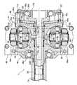
図4および図5から明らかなように、パワーローラ18,18が入力ディスク14および出力ディスク15に対してスリップしないように付勢手段22の油室21に油圧を供給すると、入力軸13に固定されたピストン20に対して入力ディスク14が図中左側に付勢され、パワーローラ18,18を出力ディスク15に押し付ける。言い換えると、出力ディスク15はパワーローラ18,18から受ける反力で図中左側に荷重FL1で付勢され、その荷重FL1は出力ディスク15から第2スラストベアリング26Bを介して第2支持部材46に伝達され、第2支持部材46を図中左側に荷重FL2で付勢する。一方、入力ディスク14はパワーローラ18,18から受ける反力で図中右側に荷重FR1で付勢され、その荷重FR1は入力ディスク15から油室21、ピストン20、入力軸13の大径部13aおよび第1スラストベアリング26Aを介して第1支持部材45に伝達され、第1支持部材45を図中右側に荷重FR2で付勢する。 As apparent from FIGS. 4 and 5, when hydraulic pressure is supplied to the
しかしながら、第1支持部材45および第2支持部材46はベース部材41および連結部材49を介して一体に結合されているため、左向きの荷重FL2および右向きの荷重FR2はベース部材41および連結部材49を入力軸13の軸方向に引っ張るように作用するだけであり、その荷重FL2,FR2がベース部材41および連結部材49の内部応力FL2′,FR2′に釣り合うことで、入力軸13に軸方向の荷重が伝達されることはない。 However, since the
入力軸13について考えると、パワーローラ18,18が入力ディスク14を右向きに付勢する反力FR1は入力軸13の右端の大径部13aを右向きに付勢するが、パワーローラ18が出力ディスク15を左向きに付勢する反力FL1は、出力ディスク15が入力軸13に対して軸方向摺動可能であることから、入力軸13を左向きに付勢することはなく、よって入力軸13に軸方向の引張荷重が作用することはない。 Considering the
このように、パワーローラ18,18から入力ディスク14および出力ディスク15が受ける相互に逆方向の荷重FL1,FR1は最終的にベース部材41および連結部材49の内部応力FL2′,FR2′によって受け止められるため、入力軸13にはトルク伝達による捩じり荷重が作用するだけで軸方向の引張荷重は作用しなくなり、入力軸13の直径を減少させてトロイダル型無段変速機構Tの小型軽量化を図ることができる。 As described above, the loads FL1 and FR1 in the opposite directions received by the
しかも第1支持部材45を連結部材49に結合するボルト51,51と、第2支持部材46を連結部材49に結合するボルト52,52とは、荷重FL2,FR2が作用する方向に沿って配置されているため、それらのボルト51,51;52,52を小径にしても荷重FL2,FR2を確実に伝達することができるだけでなく、ボルト51,51;52,52の緩みを防止することができる。 Moreover, the
また第2スラストベアリング26Bのインナーレースと出力ディスク15の段部との間に配置されるシム72の厚さを決定するときに、図4において、連結部材49の端面aと出力ディスク15の段部bとの距離Dを測定する必要があるが、第2支持部材46を締結するボルト52,52を入力軸13の軸方向に配置したことで、ボルト52,52の軸線に対して直交する前記端面aおよび前記段部bを利用して前記距離Dを測定を容易に行うことができ、作業性が向上する。 When determining the thickness of the
以上、本発明の実施の形態を説明したが、本発明はその要旨を逸脱しない範囲で種々の設計変更を行うことが可能である。 The embodiments of the present invention have been described above, but various design changes can be made without departing from the scope of the present invention.
例えば、第1支持部材45、第2支持部材46および連結部材49の形状は実施の形態に限定されるものではない。 For example, the shapes of the
13 入力軸
14 入力ディスク
15 出力ディスク
17 トラニオン軸
18 パワーローラ
22 付勢手段
26A 第1スラストベアリング(第1ベアリング)
26B 第2スラストベアリング(第2ベアリング)
41 ベース部材
45 第1支持部材
46 第2支持部材
49 連結部材
51 ボルト
52 ボルト
55 トラニオン
72 シム
a 連結部材の端面
b 出力ディスクの段部(出力ディスクの側面)13
26B Second thrust bearing (second bearing)
41
Claims (3)
Translated fromJapanese前記入力ディスク(14)側で前記入力軸(13)を支持する第1ベアリング(26A)と、前記出力ディスク(15)を支持する第2ベアリング(26B)と、一端側が前記ベース部材(41)に固定されて前記第1ベアリング(26A)を支持する第1支持部材(45)と、一端側が前記ベース部材(41)に固定されて前記第2ベアリング(26B)を支持する第2支持部材(46)と、前記第1、第2支持部材(45,46)の他端側を連結する連結部材(49)とを備えることを特徴とするトロイダル型無段変速機構。An input disk (14) supported on the input shaft (13) so as not to be relatively rotatable and slidable in the axial direction, and an output disk (15) supported on the input shaft (13) so as to be relatively rotatable and slidable in the axial direction. ), A pair of power rollers (18) sandwiched between the input disk (14) and the output disk (15), and the input disk (14) with respect to the input shaft (13). 15) The urging means (22) that urges the pair of power rollers (18) in a direction approaching the pair of power rollers (18), the base member (41), and the pair of power rollers (18) can be tilted. A toroidal continuously variable transmission mechanism comprising a pair of trunnions (55) supported and slidably supported in the direction of the trunnion shaft (17) by the base member (41);
A first bearing (26A) for supporting the input shaft (13) on the input disk (14) side, a second bearing (26B) for supporting the output disk (15), and one end side of the base member (41) A first support member (45) that is fixed to the first bearing (26A) and a second support member (one end side is fixed to the base member (41) and supports the second bearing (26B)). 46) and a connecting member (49) for connecting the other end of the first and second support members (45, 46) to each other, a toroidal continuously variable transmission mechanism.
Priority Applications (4)
| Application Number | Priority Date | Filing Date | Title |
|---|---|---|---|
| JP2012070678AJP2013204604A (en) | 2012-03-27 | 2012-03-27 | Toroidal continuously variable transmission mechanism |
| CN2013100666713ACN103363047A (en) | 2012-03-27 | 2013-03-04 | Toroidal continuously variable transmission mechanism |
| US13/827,920US20130260954A1 (en) | 2012-03-27 | 2013-03-14 | Toroidal continuously variable transmission mechanism |
| DE201310205135DE102013205135A1 (en) | 2012-03-27 | 2013-03-22 | Stepless torsion mechanism |
Applications Claiming Priority (1)
| Application Number | Priority Date | Filing Date | Title |
|---|---|---|---|
| JP2012070678AJP2013204604A (en) | 2012-03-27 | 2012-03-27 | Toroidal continuously variable transmission mechanism |
Publications (1)
| Publication Number | Publication Date |
|---|---|
| JP2013204604Atrue JP2013204604A (en) | 2013-10-07 |
Family
ID=49154953
Family Applications (1)
| Application Number | Title | Priority Date | Filing Date |
|---|---|---|---|
| JP2012070678APendingJP2013204604A (en) | 2012-03-27 | 2012-03-27 | Toroidal continuously variable transmission mechanism |
Country Status (4)
| Country | Link |
|---|---|
| US (1) | US20130260954A1 (en) |
| JP (1) | JP2013204604A (en) |
| CN (1) | CN103363047A (en) |
| DE (1) | DE102013205135A1 (en) |
Cited By (2)
| Publication number | Priority date | Publication date | Assignee | Title |
|---|---|---|---|---|
| JP2017003044A (en)* | 2015-06-12 | 2017-01-05 | 日本精工株式会社 | Continuously variable transmission |
| JP2021060099A (en)* | 2019-10-09 | 2021-04-15 | 川崎重工業株式会社 | Toroidal continuously variable transmission |
Families Citing this family (5)
| Publication number | Priority date | Publication date | Assignee | Title |
|---|---|---|---|---|
| GB0920546D0 (en)* | 2009-11-24 | 2010-01-06 | Torotrak Dev Ltd | Drive mechanism for infinitely variable transmission |
| JP2015017664A (en)* | 2013-07-11 | 2015-01-29 | 日本精工株式会社 | Electric vehicle drive |
| JP2015083864A (en)* | 2013-09-20 | 2015-04-30 | 日本精工株式会社 | Toroidal continuously variable transmission and continuously variable transmission |
| US10436294B2 (en)* | 2014-04-02 | 2019-10-08 | Nsk Ltd. | Toroidal continuously variable transmission |
| JP6090634B2 (en)* | 2014-04-22 | 2017-03-08 | 本田技研工業株式会社 | Half toroidal continuously variable transmission |
Family Cites Families (7)
| Publication number | Priority date | Publication date | Assignee | Title |
|---|---|---|---|---|
| US2157259A (en)* | 1937-04-09 | 1939-05-09 | Gen Motors Corp | Variable speed transmission |
| US3142190A (en)* | 1963-02-20 | 1964-07-28 | Curtiss Wright Corp | Ratio control system for toroidal transmission |
| US3299744A (en)* | 1963-09-04 | 1967-01-24 | Excelermatic | Toroidal-type transmission |
| JP2979945B2 (en)* | 1993-12-17 | 1999-11-22 | 日産自動車株式会社 | Friction wheel type continuously variable transmission |
| JP3428304B2 (en) | 1996-08-07 | 2003-07-22 | 日産自動車株式会社 | Toroidal type continuously variable transmission |
| JP3498906B2 (en)* | 2000-05-12 | 2004-02-23 | 日産自動車株式会社 | Toroidal type continuously variable transmission |
| JP5400010B2 (en) | 2010-09-29 | 2014-01-29 | 関西ペイント株式会社 | Enzyme or microorganism immobilization carrier |
- 2012
- 2012-03-27JPJP2012070678Apatent/JP2013204604A/enactivePending
- 2013
- 2013-03-04CNCN2013100666713Apatent/CN103363047A/enactivePending
- 2013-03-14USUS13/827,920patent/US20130260954A1/ennot_activeAbandoned
- 2013-03-22DEDE201310205135patent/DE102013205135A1/ennot_activeCeased
Cited By (5)
| Publication number | Priority date | Publication date | Assignee | Title |
|---|---|---|---|---|
| JP2017003044A (en)* | 2015-06-12 | 2017-01-05 | 日本精工株式会社 | Continuously variable transmission |
| JP2021060099A (en)* | 2019-10-09 | 2021-04-15 | 川崎重工業株式会社 | Toroidal continuously variable transmission |
| WO2021070816A1 (en)* | 2019-10-09 | 2021-04-15 | 川崎重工業株式会社 | Toroidal continuously variable transmission |
| JP7469863B2 (en) | 2019-10-09 | 2024-04-17 | 川崎重工業株式会社 | Toroidal Continuously Variable Transmission |
| US12060925B2 (en) | 2019-10-09 | 2024-08-13 | Kawasaki Jukogyo Kabushiki Kaisha | Toroidal continuously variable transmission |
Also Published As
| Publication number | Publication date |
|---|---|
| CN103363047A (en) | 2013-10-23 |
| US20130260954A1 (en) | 2013-10-03 |
| DE102013205135A1 (en) | 2013-10-02 |
Similar Documents
| Publication | Publication Date | Title |
|---|---|---|
| JP2013204604A (en) | Toroidal continuously variable transmission mechanism | |
| US20130053211A1 (en) | Toroidal continuously variable transmission | |
| CN104321560B (en) | transmission | |
| US6514168B2 (en) | Toroidal type continuous variable speed transmission | |
| US9211882B2 (en) | Drive control device | |
| JP6179332B2 (en) | Toroidal continuously variable transmission | |
| JP5819240B2 (en) | Toroidal continuously variable transmission mechanism | |
| JP6003732B2 (en) | Toroidal continuously variable transmission | |
| JP5177576B2 (en) | Toroidal continuously variable transmission | |
| JP2012197911A (en) | Toroidal type continuously variable transmission | |
| JP2002349648A (en) | Continuously variable transmission | |
| JP6766382B2 (en) | Toroidal continuously variable transmission | |
| JP4815785B2 (en) | Toroidal continuously variable transmission | |
| JP2013024309A (en) | Continuously variable transmission | |
| JP2014058988A (en) | Toroidal type continuously variable transmission | |
| CN1997841A (en) | Toroidal type stepless speed change device | |
| JP2012177394A (en) | Toroidal continuously variable transmission | |
| JP2008082371A (en) | Toroidal continuously variable transmission and manufacturing method thereof | |
| JP2010216516A (en) | Friction transmission device | |
| JPH09269040A (en) | Toroidal continuously variable transmission | |
| JP2007205546A (en) | Toroidal continuously variable transmission | |
| JP2015152145A (en) | Toroidal continuously variable transmission | |
| JP2002021969A (en) | Continuously variable transmission | |
| JP2013145027A (en) | Toroidal type continuously variable transmission | |
| JP2016003720A (en) | Toroidal continuously variable transmission |