JP2013203394A - Base station for transportation means - Google Patents
Base station for transportation meansDownload PDFInfo
- Publication number
- JP2013203394A JP2013203394AJP2013058590AJP2013058590AJP2013203394AJP 2013203394 AJP2013203394 AJP 2013203394AJP 2013058590 AJP2013058590 AJP 2013058590AJP 2013058590 AJP2013058590 AJP 2013058590AJP 2013203394 AJP2013203394 AJP 2013203394A
- Authority
- JP
- Japan
- Prior art keywords
- battery
- vehicle
- bay
- platform
- base station
- Prior art date
- Legal status (The legal status is an assumption and is not a legal conclusion. Google has not performed a legal analysis and makes no representation as to the accuracy of the status listed.)
- Granted
Links
Images


Classifications
- H—ELECTRICITY
- H01—ELECTRIC ELEMENTS
- H01M—PROCESSES OR MEANS, e.g. BATTERIES, FOR THE DIRECT CONVERSION OF CHEMICAL ENERGY INTO ELECTRICAL ENERGY
- H01M10/00—Secondary cells; Manufacture thereof
- H01M10/42—Methods or arrangements for servicing or maintenance of secondary cells or secondary half-cells
- H01M10/46—Accumulators structurally combined with charging apparatus
- B—PERFORMING OPERATIONS; TRANSPORTING
- B60—VEHICLES IN GENERAL
- B60L—PROPULSION OF ELECTRICALLY-PROPELLED VEHICLES; SUPPLYING ELECTRIC POWER FOR AUXILIARY EQUIPMENT OF ELECTRICALLY-PROPELLED VEHICLES; ELECTRODYNAMIC BRAKE SYSTEMS FOR VEHICLES IN GENERAL; MAGNETIC SUSPENSION OR LEVITATION FOR VEHICLES; MONITORING OPERATING VARIABLES OF ELECTRICALLY-PROPELLED VEHICLES; ELECTRIC SAFETY DEVICES FOR ELECTRICALLY-PROPELLED VEHICLES
- B60L53/00—Methods of charging batteries, specially adapted for electric vehicles; Charging stations or on-board charging equipment therefor; Exchange of energy storage elements in electric vehicles
- B60L53/80—Exchanging energy storage elements, e.g. removable batteries
- B—PERFORMING OPERATIONS; TRANSPORTING
- B64—AIRCRAFT; AVIATION; COSMONAUTICS
- B64F—GROUND OR AIRCRAFT-CARRIER-DECK INSTALLATIONS SPECIALLY ADAPTED FOR USE IN CONNECTION WITH AIRCRAFT; DESIGNING, MANUFACTURING, ASSEMBLING, CLEANING, MAINTAINING OR REPAIRING AIRCRAFT, NOT OTHERWISE PROVIDED FOR; HANDLING, TRANSPORTING, TESTING OR INSPECTING AIRCRAFT COMPONENTS, NOT OTHERWISE PROVIDED FOR
- B64F1/00—Ground or aircraft-carrier-deck installations
- B64F1/22—Ground or aircraft-carrier-deck installations for handling aircraft
- B—PERFORMING OPERATIONS; TRANSPORTING
- B64—AIRCRAFT; AVIATION; COSMONAUTICS
- B64U—UNMANNED AERIAL VEHICLES [UAV]; EQUIPMENT THEREFOR
- B64U50/00—Propulsion; Power supply
- B64U50/10—Propulsion
- B64U50/19—Propulsion using electrically powered motors
- B—PERFORMING OPERATIONS; TRANSPORTING
- B64—AIRCRAFT; AVIATION; COSMONAUTICS
- B64U—UNMANNED AERIAL VEHICLES [UAV]; EQUIPMENT THEREFOR
- B64U50/00—Propulsion; Power supply
- B64U50/30—Supply or distribution of electrical power
- B64U50/39—Battery swapping
- B—PERFORMING OPERATIONS; TRANSPORTING
- B64—AIRCRAFT; AVIATION; COSMONAUTICS
- B64U—UNMANNED AERIAL VEHICLES [UAV]; EQUIPMENT THEREFOR
- B64U80/00—Transport or storage specially adapted for UAVs
- B64U80/80—Transport or storage specially adapted for UAVs by vehicles
- B64U80/86—Land vehicles
- H—ELECTRICITY
- H01—ELECTRIC ELEMENTS
- H01M—PROCESSES OR MEANS, e.g. BATTERIES, FOR THE DIRECT CONVERSION OF CHEMICAL ENERGY INTO ELECTRICAL ENERGY
- H01M10/00—Secondary cells; Manufacture thereof
- H01M10/42—Methods or arrangements for servicing or maintenance of secondary cells or secondary half-cells
- H01M10/4207—Methods or arrangements for servicing or maintenance of secondary cells or secondary half-cells for several batteries or cells simultaneously or sequentially
- H—ELECTRICITY
- H01—ELECTRIC ELEMENTS
- H01M—PROCESSES OR MEANS, e.g. BATTERIES, FOR THE DIRECT CONVERSION OF CHEMICAL ENERGY INTO ELECTRICAL ENERGY
- H01M50/00—Constructional details or processes of manufacture of the non-active parts of electrochemical cells other than fuel cells, e.g. hybrid cells
- H01M50/20—Mountings; Secondary casings or frames; Racks, modules or packs; Suspension devices; Shock absorbers; Transport or carrying devices; Holders
- H01M50/256—Carrying devices, e.g. belts
- H—ELECTRICITY
- H02—GENERATION; CONVERSION OR DISTRIBUTION OF ELECTRIC POWER
- H02J—CIRCUIT ARRANGEMENTS OR SYSTEMS FOR SUPPLYING OR DISTRIBUTING ELECTRIC POWER; SYSTEMS FOR STORING ELECTRIC ENERGY
- H02J7/00—Circuit arrangements for charging or depolarising batteries or for supplying loads from batteries
- H02J7/0042—Circuit arrangements for charging or depolarising batteries or for supplying loads from batteries characterised by the mechanical construction
- H02J7/0045—Circuit arrangements for charging or depolarising batteries or for supplying loads from batteries characterised by the mechanical construction concerning the insertion or the connection of the batteries
- B—PERFORMING OPERATIONS; TRANSPORTING
- B60—VEHICLES IN GENERAL
- B60L—PROPULSION OF ELECTRICALLY-PROPELLED VEHICLES; SUPPLYING ELECTRIC POWER FOR AUXILIARY EQUIPMENT OF ELECTRICALLY-PROPELLED VEHICLES; ELECTRODYNAMIC BRAKE SYSTEMS FOR VEHICLES IN GENERAL; MAGNETIC SUSPENSION OR LEVITATION FOR VEHICLES; MONITORING OPERATING VARIABLES OF ELECTRICALLY-PROPELLED VEHICLES; ELECTRIC SAFETY DEVICES FOR ELECTRICALLY-PROPELLED VEHICLES
- B60L2200/00—Type of vehicles
- B60L2200/10—Air crafts
- H—ELECTRICITY
- H01—ELECTRIC ELEMENTS
- H01M—PROCESSES OR MEANS, e.g. BATTERIES, FOR THE DIRECT CONVERSION OF CHEMICAL ENERGY INTO ELECTRICAL ENERGY
- H01M2220/00—Batteries for particular applications
- H01M2220/20—Batteries in motive systems, e.g. vehicle, ship, plane
- Y—GENERAL TAGGING OF NEW TECHNOLOGICAL DEVELOPMENTS; GENERAL TAGGING OF CROSS-SECTIONAL TECHNOLOGIES SPANNING OVER SEVERAL SECTIONS OF THE IPC; TECHNICAL SUBJECTS COVERED BY FORMER USPC CROSS-REFERENCE ART COLLECTIONS [XRACs] AND DIGESTS
- Y02—TECHNOLOGIES OR APPLICATIONS FOR MITIGATION OR ADAPTATION AGAINST CLIMATE CHANGE
- Y02E—REDUCTION OF GREENHOUSE GAS [GHG] EMISSIONS, RELATED TO ENERGY GENERATION, TRANSMISSION OR DISTRIBUTION
- Y02E60/00—Enabling technologies; Technologies with a potential or indirect contribution to GHG emissions mitigation
- Y02E60/10—Energy storage using batteries
- Y—GENERAL TAGGING OF NEW TECHNOLOGICAL DEVELOPMENTS; GENERAL TAGGING OF CROSS-SECTIONAL TECHNOLOGIES SPANNING OVER SEVERAL SECTIONS OF THE IPC; TECHNICAL SUBJECTS COVERED BY FORMER USPC CROSS-REFERENCE ART COLLECTIONS [XRACs] AND DIGESTS
- Y02—TECHNOLOGIES OR APPLICATIONS FOR MITIGATION OR ADAPTATION AGAINST CLIMATE CHANGE
- Y02T—CLIMATE CHANGE MITIGATION TECHNOLOGIES RELATED TO TRANSPORTATION
- Y02T10/00—Road transport of goods or passengers
- Y02T10/60—Other road transportation technologies with climate change mitigation effect
- Y02T10/70—Energy storage systems for electromobility, e.g. batteries
- Y—GENERAL TAGGING OF NEW TECHNOLOGICAL DEVELOPMENTS; GENERAL TAGGING OF CROSS-SECTIONAL TECHNOLOGIES SPANNING OVER SEVERAL SECTIONS OF THE IPC; TECHNICAL SUBJECTS COVERED BY FORMER USPC CROSS-REFERENCE ART COLLECTIONS [XRACs] AND DIGESTS
- Y02—TECHNOLOGIES OR APPLICATIONS FOR MITIGATION OR ADAPTATION AGAINST CLIMATE CHANGE
- Y02T—CLIMATE CHANGE MITIGATION TECHNOLOGIES RELATED TO TRANSPORTATION
- Y02T10/00—Road transport of goods or passengers
- Y02T10/60—Other road transportation technologies with climate change mitigation effect
- Y02T10/7072—Electromobility specific charging systems or methods for batteries, ultracapacitors, supercapacitors or double-layer capacitors
Landscapes
- Engineering & Computer Science (AREA)
- Chemical & Material Sciences (AREA)
- Aviation & Aerospace Engineering (AREA)
- Combustion & Propulsion (AREA)
- Mechanical Engineering (AREA)
- Electrochemistry (AREA)
- Chemical Kinetics & Catalysis (AREA)
- General Chemical & Material Sciences (AREA)
- Manufacturing & Machinery (AREA)
- Transportation (AREA)
- Power Engineering (AREA)
- Remote Sensing (AREA)
- Vehicle Cleaning, Maintenance, Repair, Refitting, And Outriggers (AREA)
- Charge And Discharge Circuits For Batteries Or The Like (AREA)
- Arrangement Or Mounting Of Propulsion Units For Vehicles (AREA)
- Closed-Circuit Television Systems (AREA)
- Battery Mounting, Suspending (AREA)
- Electric Propulsion And Braking For Vehicles (AREA)
Abstract
Translated fromJapaneseDescription
Translated fromJapaneseここに説明する主題は、輸送手段ベースステーションに関し、より詳細には、無人機(UAV)などの1つ以上の自律輸送手段に材料を装着するためのプラットフォームを含む輸送手段ベースステーションに関する。 The subject matter described herein relates to a vehicle base station, and more particularly to a vehicle base station that includes a platform for loading material into one or more autonomous vehicles such as an unmanned aerial vehicle (UAV).
自律輸送手段は、産業、法の執行および軍事用途においてますます有用となってきている。自律輸送手段の例としては、無線誘導式無人航空機およびロボット輸送手段が挙げられる。いくつかの自律輸送手段は、電池により少なくとも部分的に電力供給されている。したがって、電池電力により、とりわけ遠隔地での自律輸送手段の持続的使用の能力が著しく限定される。したがって、自律輸送手段が電池やその他のペイロードを取り外し、新しい電池やその他のペイロードを再装着することができるようにするシステムおよび方法が有用である可能性がある。 Autonomous vehicles are becoming increasingly useful in industrial, law enforcement and military applications. Examples of autonomous transportation means include wireless guided unmanned aircraft and robot transportation means. Some autonomous transport means are at least partially powered by batteries. Thus, battery power significantly limits the ability to sustainably use autonomous vehicles, especially in remote locations. Thus, systems and methods that allow an autonomous vehicle to remove a battery or other payload and reinsert a new battery or other payload may be useful.
輸送手段に対して電池を脱着するためのシステムの一例をここに説明する。いくつかの実施形態において、輸送手段ベースステーションは、輸送手段を位置付けてもよいプラットフォームと、プラットフォームの第1の側に位置している第1電池ベイと、輸送手段から電池を取り外し、該電池を新たな電池と交換する電池交換アセンブリと、輸送手段がプラットフォーム上に位置付けられている際に輸送手段に電力を供給するよう適合されている電源とを含む。 An example of a system for detaching a battery from a vehicle will now be described. In some embodiments, the vehicle base station removes the battery from the vehicle, removes the battery from the vehicle, a platform on which the vehicle may be located, a first battery bay located on the first side of the platform. A battery replacement assembly for replacing a new battery, and a power source adapted to supply power to the vehicle when the vehicle is positioned on the platform.
別の実施形態において、システムは、輸送手段に据え付け可能な基部および基部に結合されている経路を有する第1フレームを含む電池受け部と、1つ以上の電池を保持することができる第2フレーム、第2フレーム上に据え付けられており、かつ、電池受け部フレームの基部に結合されている経路にはめ込まれるよう適合されているレールを含む電池台部と、輸送手段を位置付けてもよいプラットフォーム、プラットフォームの第1の側に位置している第1電池ベイ、第1の側とは反対のプラットフォームの第2の側に位置している第2電池ベイ、輸送手段から電池を取り除き、電池を新たな電池と交換する電池交換アセンブリ、および、輸送手段をプラットフォーム上に位置付けている間に輸送手段に電力を供給するよう適合されている電源を含む輸送手段ベースステーションと、を含む。 In another embodiment, a system includes a battery receiver that includes a base that is mountable to a vehicle and a first frame that has a path coupled to the base, and a second frame that can hold one or more batteries. A battery platform including rails mounted on the second frame and adapted to fit into a path coupled to the base of the battery receiver frame; and a platform on which the vehicle may be positioned; A first battery bay located on the first side of the platform, a second battery bay located on the second side of the platform opposite to the first side, removing the battery from the means of transport and renewing the battery Battery replacement assembly for replacing a new battery and adapted to supply power to the vehicle while the vehicle is positioned on the platform It includes a vehicle base station including a source, a.
別の実施形態において、輸送手段上の電池を交換する方法は、輸送手段ベースステーションのプラットフォーム上に輸送手段を位置付けること、輸送手段が輸送手段ベースステーション上に位置付けられている間に輸送手段に連続的に電力を供給すること、充電済み電池を含む第1電池ベイを輸送手段に結合されている電池受け部の第1の側に位置合わせすること、空の第2電池ベイを第1の側と反対の電池受け部の第2の側に位置合わせすること、第1電池ベイから輸送手段に結合されている電池受け部上へと第1電池を摺動させること、および、輸送手段に結合されている電池受け部から第2電池ベイ上へと第2電池を摺動させること、を含む。 In another embodiment, a method for exchanging a battery on a vehicle includes positioning the vehicle on a platform of the vehicle base station and continuing to the vehicle while the vehicle is positioned on the vehicle base station. Supplying electric power, aligning a first battery bay containing a charged battery with a first side of a battery receptacle coupled to the means of transport, an empty second battery bay on a first side Aligning to the second side of the battery receptacle opposite the first battery, sliding the first battery from the first battery bay onto the battery receptacle coupled to the vehicle, and coupling to the vehicle Sliding the second battery onto the second battery bay from the battery receiving portion being provided.
添付の図を参照しつつ、詳細な説明を記す。
以下の説明において、さまざまな実施形態の完全な理解をもたらすために数多くの特定の詳細を記載する。ただし、特定の詳細なしにさまざまな実施形態を実施可能であることは当業者により理解されるだろう。その他の場合、特定の実施形態をあいまいなものとしないように、よく知られている方法、手順、構成部品および要素を詳細には例示も説明もしていない。 In the following description, numerous specific details are set forth in order to provide a thorough understanding of various embodiments. However, it will be understood by one of ordinary skill in the art that various embodiments may be practiced without specific details. In other instances, well-known methods, procedures, components, and elements have not been illustrated or described in detail so as not to obscure the specific embodiments.
無人機(UAV)環境を参照しつつ、輸送手段装着プラットフォームの一実施形態を説明する。無人機(UAV)は、航空機に人間の操縦者が不在の状態で飛行可能な航空機である。無人機は、遠隔地から制御されてもよい。この遠隔地において、人間の操作者またはコンピュータにより実行されるプログラムは、無人機に対するコマンドを生成する。無人機はまた、無人機上のコンピュータまたはその他の制御装置上で走るプログラムを用いて制御されてもよい。 One embodiment of a vehicle mounting platform will be described with reference to an unmanned aerial vehicle (UAV) environment. An unmanned aerial vehicle (UAV) is an aircraft that can fly in the absence of a human pilot on the aircraft. The drone may be controlled from a remote location. At this remote location, a program executed by a human operator or computer generates a command for the drone. The drone may also be controlled using a program that runs on a computer or other control device on the drone.
無人機は、ある数の種々の目的のために用いられる。軍事および安全保障用途では、無人機は、例えば限定はされないが、偵察任務、攻撃任務および/またはその他適切な種類の任務を含む可能性のある任務を遂行するために用いられてもよい。無人機はまた、ある数の民間用途においても用いることができる。例えば限定はされないが、無人機は、測量、消火および/またはその他適切な種類の任務の遂行に用いられてもよい。 The drone is used for a number of different purposes. In military and security applications, drones may be used to perform missions that may include, for example, but not limited to reconnaissance missions, attack missions, and / or other suitable types of missions. The drone can also be used in a number of civilian applications. For example, without limitation, the drone may be used for surveying, extinguishing and / or performing other suitable types of missions.
無人機は、ある数の種々の大きさおよび形状であってもよい。無人機は、例えば、固定翼航空機、ヘリコプターおよび/または羽ばたき機の形態を取ってもよい。例えば限定はされないが、無人機は、飛行機、ヘリコプターまたは飛行可能なその他何らかの適切な種類の装置の形態を取ってもよい。無人機の大きさは、多種多様であってもよい。例えば、無人機は、無人機の種類によって、約数インチから約200フィートまでの翼幅を有していてもよい。 The drone may be in a number of different sizes and shapes. The drone may take the form of, for example, a fixed wing aircraft, a helicopter and / or a flapping aircraft. For example, without limitation, the drone may take the form of an airplane, helicopter or any other suitable type of device capable of flying. The size of the drone may vary widely. For example, the drone may have a wingspan from about a few inches to about 200 feet, depending on the type of drone.
より小型の無人機は、超小型飛行機と呼ばれる。これらの種類の航空輸送手段は、人間によって運搬されるよう構成されていてもよく、かつ、空中に超小型飛行機を投げることにより飛ばしてもよい。これらの種類の航空輸送手段が小型であることにより、これらの航空輸送手段が飛行を開始するために十分な速度を与えるこの種の飛ばし方が可能となる。これらの種類の輸送手段用のセンサー、モーター、電力供給装置および制御装置の小型化に起因して、無人機がいくぶん小型化してきている。 Smaller drones are called micro airplanes. These types of air transport means may be configured to be transported by humans and may be blown by throwing a micro airplane into the air. The small size of these types of air transport means allows for this type of flight that provides sufficient speed for these air transport means to begin flying. Due to the miniaturization of sensors, motors, power supply and control devices for these types of means of transportation, drones have become somewhat smaller.
輸送手段の小型化およびコスト低減により、これらの輸送手段を多数運転することが可能となる。例えば、超小型飛行機(MAV)は、より大型の無人機を1機または2機運転することと比較して、およそ分隊または小隊の大きさである数で運転可能である。この種の運転により、ある特定の領域に対して行うことのできる監視が強化される。この種の無人機はまた、高台、建物または別の地点に着陸してもよい。このようにして、超小型飛行機は、飛行を続ける必要なしにある特定の地点を監視可能である。超小型飛行機は、目的の領域が変われば、位置付けし直してもよい。 Due to the downsizing and cost reduction of the transportation means, it is possible to operate a large number of these transportation means. For example, a micro air vehicle (MAV) can be operated with numbers that are approximately the size of a squad or platoon compared to operating one or two larger drones. This type of operation enhances the monitoring that can be performed on a particular area. This type of drone may also land on hills, buildings or other points. In this way, the micro air vehicle can monitor a specific point without having to continue flying. The micro air plane may be repositioned if the target area changes.
例えば、超小型飛行機は、都市または町の建物に着陸してもよい。超小型飛行機は、都市におけるある特定の道路または建物を監視してもよい。ただし、超小型飛行機は、より大型の無人機と比較して、その小型であることにより制限がある。例えば、より大型の無人機と比較して、超小型飛行機では、処理能力およびデータ伝送距離がより限定されている可能性がある。さらに、より大型の無人機と比較して、これら超小型飛行機の航続距離は短い可能性がある。 For example, a micro air plane may land in a city or town building. A micro air vehicle may monitor certain roads or buildings in a city. However, ultra-compact airplanes are limited by their small size compared to larger drones. For example, compared to a larger unmanned aerial vehicle, a micro-aircraft may have more limited processing power and data transmission distance. Furthermore, the cruising range of these micro air vehicles may be short compared to larger drones.
ここに説明するさまざまな実施形態は、無人機を含む自律輸送手段用の輸送手段ベースステーションを提供する。いくつかの実施形態において、ベースステーションは、ペイロードを運搬している少なくとも1つの輸送手段を支持する少なくとも1つのプラットフォームを規定するハウジングと、プラットフォーム上の所望の地点にペイロードを位置合わせする輸送手段ドッキングアセンブリと、輸送手段からペイロードを取り外し、ペイロードを新たなペイロードに交換するペイロード交換アセンブリとを含む。以下の図を参照しつつ、輸送手段ベースステーションおよび無人機の実施形態のさまざまな側面を説明する。 The various embodiments described herein provide a vehicle base station for autonomous vehicles including drones. In some embodiments, the base station includes a housing defining at least one platform that supports at least one vehicle carrying the payload and a vehicle dock that aligns the payload at a desired point on the platform. And an assembly for removing the payload from the vehicle and exchanging the payload for a new payload. Various aspects of the vehicle base station and drone embodiments will be described with reference to the following figures.
図1を参照して、ある実施形態に係る無人機環境の図を描写する。無人機環境100は、無人機ベースステーション102、無人機ベースステーション104および無人機ベースステーション106を含む。 With reference to FIG. 1, a diagram of an unmanned aerial vehicle environment according to an embodiment is depicted. The
図1で描写している実施例において、無人機ベースステーション102は、町112内の建物110の屋上108に位置している。無人機ベースステーション104は、輸送手段114に関連付けられている。第1構成要素は、第2構成要素に固定され、第2構成要素に接着され、第2構成要素に締め付けられ、かつ/または、その他何らかの適切な手法で第2構成要素と接続されることにより、第2構成要素に関連付けられていると考えられてもよい。第1構成要素はまた、第3構成要素により第2構成要素と接続されていてもよい。第1構成要素は、第2構成要素の一部および/または第2構成要素の延長として形成されることにより、第2構成要素に関連付けられていると考えられてもよい。 In the embodiment depicted in FIG. 1, the
無人機ベースステーション106は、電力線116上に位置している。無人機ベースステーション102、104および106は、ある数の種々の方法で配備されていてもよい。無人機ベースステーション102は、ヘリコプターにより屋上108に落下させてもよい。屋上108における無人機ベースステーション102の地点により、結果として、無人機ベースステーション102が見えにくくなる可能性がある。さらに、この地点により、無人機ベースステーション102と通信アレイとの間でより良好な見通し線がもたらされることがある。このようにして、無人機ベースステーション102が無人機と通信可能な範囲を拡大してもよい。 The
無人機ベースステーション104は、輸送手段114に関連付けられている。輸送手段114に関連付けられることにより、無人機ベースステーション104は、周期的にまたは常に移動させられていてもよい。この種の配備により、無人機ベースステーション104の発見可能性が低減する可能性がある。さらに、無人機ベースステーション104に可動性を与えることにより、任務を遂行するための柔軟性がより高くなってもよい。これに加えて、無人機ベースステーション104は、輸送手段114から取り外され、地上にまたはその他何らかの適切な地点に設置されてもよい。 The
無人機ベースステーション106は、ヘリコプターにより、パラシュート上から、または、その他何らかの適切な機構により落下させられることにより、電力線116上に配備されてもよい。無人機ベースステーション106は、電力線116上ではより見えにくい可能性がある。描写されているように、無人機118、120、122、124、126、128、130、132、134、136および138といった無人機は、無人機ベースステーション102、104および106から操縦されてもよい。 The
これらの説明例において、無人機ベースステーション102、104および106は、基地を提供し、該基地から、種々の無人機が、データを送信し、命令を受信し、再充電し、保管され、かつ/または、その他の動作を行う。 In these illustrative examples, the
また、無人機は、ベースステーションからベースステーションへ移動してもよい。言い換えると、無人機ベースステーション102、104および106は、無人機の航続距離を延長するためのネットワークを提供してもよい。複数の無人機ベースステーションを有することで、1つの無人機ベースステーションが誤動作したり、必要な機能を示さない場合のバックアップを提供することもできる。 The drone may move from the base station to the base station. In other words, the
描写されている本実施例で理解できるように、無人機ベースステーション102、104および106は、これらのベースステーションの探知を低減可能な地点に設置してもよい。これらの地点は、特定の本実施例において説明するもの以外のその他の地点を含んでいてもよい。例えば、無人機ベースステーション102、104および106は、木々の中、茂みの中および/またはその他適切な地点に設置されてもよい。 As can be seen in the depicted example, the
無人機は、無人機環境100においてある数の種々の任務を遂行するために用いられてもよい。本説明例において、無人機は、望ましくない活動がないか監視してもよい。例えば、望ましくない活動は、車道140に簡易爆発物を設置することであってもよい。別の実施例において、無人機は、輸送手段または人間の移動を監視してもよい。さらに他の実施例では、無人機は、構造物の建築を監視するために用いられてもよい。 The drone may be used to perform a number of different missions in the
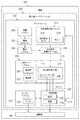
ここで図2を参照して、有利な実施形態に係る無人機ベースステーションのブロック図を描写する。無人機ベースステーション200は、図1における無人機ベースステーション102、104および106の実施に用いられてもよい無人機ベースステーションの一例である。 With reference now to FIG. 2, a block diagram of an unmanned aerial vehicle base station is depicted in accordance with an advantageous embodiment. The
本説明例において、無人機ベースステーション200は、プラットフォーム202、電池システム204、発電システム206、ある数の充電ステーション208、制御装置210、センサーシステム212および/またはその他適切な構成要素を含む。 In the illustrated example, the
プラットフォーム202は、1機以上の無人機214を保持するよう構成されている。言い換えると、ある数の無人機214は、プラットフォーム202内に設置され、かつ/または、プラットフォーム202内もしくはプラットフォーム202上に保管されていてもよい。例えば、プラットフォーム202は、ある数の無人機214が着陸可能なベイ216を有していてもよい。ベイ216は、プラットフォーム202の上側に開口を有する壁に囲まれたプラットフォーム202のある領域であってもよい。その他の有利な実施形態において、ベイ216は、プラットフォーム202の側に開口を有する壁および屋根を有していてもよい。無人機は、無人機がプラットフォーム202内へ進入するか、または、プラットフォーム202上に着陸すると、収容されると考えられる。
また、プラットフォーム202は、ある数の無人機214がプラットフォーム202内に収容されているときに、ある数の無人機214を環境224から保護するよう構成されていてもよい。
プラットフォーム202はまた、開位置220と閉位置222との間で移動するよう構成されている可動カバーシステム218を有していてもよい。可動カバーシステム218は、ベイ216を覆っていてもよい。可動カバーシステム218が開位置220にあるとき、ある数の無人機214は、プラットフォーム202から離陸し、かつ/または、プラットフォーム202内もしくはプラットフォーム202上に着陸してもよい。 The
可動カバーシステム218が閉位置222にあるとき、プラットフォーム202のベイ216内に位置しているある数の無人機214は、環境224から保護されていてもよい。さらに、閉位置222はまた、無人機ベースステーション200においてある数の無人機214を輸送するための構成をも提供する。 When the
電池システム204および発電システム206は、無人機ベースステーション200およびある数の無人機214のための電気エネルギー226を供給する。電池システム204は、任意選択可能であり、かつ、発電システム206により生成された電気エネルギー226を保存する。発電システム206は、無人機ベースステーション200が位置している環境224から電気エネルギー226を生成する。 The
ある数の充電ステーション208は、電池システム204と接続されている。充電ステーション208は、電気エネルギー226を用いてある数の無人機214用の電池を充電するよう構成されている。さらに、充電ステーション208は、無人機ベースステーション200において制御装置210およびセンサーシステム212に電気エネルギー226を供給する。 A number of charging
いくつかの実施形態において、無人機214は、液体燃料無人機の形態を取ってもよい。これらの説明例において、充電ステーション208は、これらの液体燃料無人機に燃料補給するよう構成されている。例えば、無人機ベースステーション200は、液体燃料補給システム244を有していてもよい。液体燃料補給システム244は、液体燃料を収容している液体燃料タンク246を有する。液体燃料は、例えば、ガソリンまたはディーゼル燃料であってもよい。液体燃料補給システム244内のポンプ248は、液体燃料タンク246内の液体燃料をある数の充電ステーション208へ移送する。充電ステーション208は、液体燃料無人機へ液体燃料を供給するよう構成されていてもよい。 In some embodiments, the
これらの実施形態において、制御装置210は、液体燃料補給システム244からの液体燃料のポンプによる揚水を制御するよう構成されていてもよい。いくつかの実施形態において、液体燃料補給システム244は、注射器注入システムを用いてある数の充電ステーション208における1機以上の無人機214へ液体燃料を送達してもよい。 In these embodiments, the
これらの実施形態において、制御装置210は、ある数の無人機214からセンサーデータ236を受信するよう構成されていてもよい。また、制御装置210は、センサーデータ236から情報238を生成するよう構成されていてもよい。次いで、情報238は、遠隔地240へ送信されてもよい。遠隔地240は、無人機ベースステーション200から遠く離れた地点である。遠隔地は、任務計画システムまたは人間の操作者を含んでいてもよい。制御装置210はまた、任務242を有するある数の無人機214の各々をプログラミングするよう構成されていてもよい。任務242は、ある数の無人機214の各々に対して同じであっても異なっていてもよい。 In these embodiments, the
センサーシステム212は、環境224からセンサーデータ248を生成する。センサーデータ248は、遠隔地240へ送信されてもよく、または、ある数の無人機214へコマンド250を送信するために用いられてもよい。
図2における無人機ベースステーション200の説明は、種々の有利な実施形態を実施可能な手法に対して物理的または構造上の限定を暗示することを意図しているのではない。説明したものに加えて、かつ/または、これに代えてその他の構成要素を用いてもよい。いくつかの有利な実施形態では、いくつかの構成要素が不要であることもある。また、いくつかの機能的構成要素を示すために、ブロックが提示されている。種々の実施形態において実施される際は、これらのブロックのうちの1つ以上を組み合わせ、かつ/または、種々のブロックに分割してもよい。 The description of the
例えば、いくつかの実施形態において、種々の形態のエネルギーを貯蔵装置に保存して、ある数の無人機214のための電気エネルギーに変換してもよい。これらの貯蔵装置は、電池システム204以外の装置とすることができる。これらの装置は、例えば限定はされないが、コンデンサ、フライホイール、圧縮空気装置および/またはその他適切なエネルギー貯蔵装置を含んでいてもよい。これらの装置のうちの1つ以上が充電ステーション208と接続されていてもよい。いくつかの実施形態において、ベースステーションは、輸送手段上の電池パック(またはその他のペイロード)を交換するシステムを含んでいてもよい。さらに、ベースステーションは、1つ以上の電池を再充電するアセンブリを含んでいてもよい。そのようなベースステーションの実施形態は、図8Aおよび図8Bを参照しつつ下で説明する。 For example, in some embodiments, various forms of energy may be stored in a storage device and converted to electrical energy for a number of
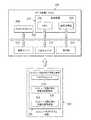
図3に注目して、ある実施形態に係るデータ処理システムのブロック図を描写する。データ処理システム300は、図2における制御装置210に対する実施構成の一例である。本説明例において、データ処理システム300は、通信機構302を含み、該通信機構302は、プロセッサユニット304、メモリ306、固定記憶域308、通信ユニット310および入出力(I/O)ユニット312の間の通信を提供する。 Turning attention to FIG. 3, a block diagram of a data processing system according to an embodiment is depicted. The
プロセッサユニット304は、メモリ306内に読み込まれてもよいソフトウェア用の命令を実行する役割を果たす。プロセッサユニット304は、特定の実施構成によって、1つ以上のプロセッサの組であっても、マルチプロセッサコアであってもよい。さらに、プロセッサユニット304は、単一のチップ上に主プロセッサが副プロセッサとともに存在する1つ以上の異種プロセッサシステムを用いて実施可能である。別の説明例として、プロセッサユニット304は、同種の複数のプロセッサを含む対称型マルチプロセッサシステムであってもよい。 The
メモリ306および固定記憶域308は、記憶装置316の一例である。記憶装置は、例えば限定はされないが、データ、機能的形態のプログラムコード、および/または、一時的かつ/または永久的いずれかのその他適切な情報といった情報を保存することができるあらゆるハードウェアである。これらの実施例において、メモリ306は、例えば、ランダムアクセスメモリまたはその他あらゆる適切な揮発性もしくは不揮発性記憶装置であってもよい。 The
固定記憶域308は、特定の実施構成によって、さまざまな形態を取ってもよい。例えば、固定記憶域308は、1つ以上の構成要素または装置を含んでもよい。例えば、固定記憶域308は、ハードドライブ、フラッシュメモリ、書き換え可能な光学ディスク、書き換え可能な磁気テープ、または、上記の何らかの組み合わせであってもよい。固定記憶域308により用いられる媒体は、着脱可能であってもよい。例えば、固定記憶域308用に着脱可能なハードドライブを用いてもよい。 The
これらの実施例において、通信ユニット310は、その他のデータ処理システムまたは装置との通信を提供する。これらの実施例において、通信ユニット310は、ネットワークインタフェースカードである。通信ユニット310は、物理的通信回線と無線通信回線とのいずれかまたは両方の使用により通信を提供してもよい。 In these illustrative examples,
通信ユニット310は、無線通信回線を提供するよう構成されている。これらの無線通信回線は、例えば限定はされないが、衛星通信回線、マイクロ波周波数通信回線、ラジオ周波数通信回線および/またはその他適切な種類の無線通信回線を含んでいてもよい。 The
入出力ユニット312は、データ処理システム300と接続可能なその他の装置に対してデータを入力および出力可能とする。例えば、入出力ユニット312は、キーボード、マウス、および/または、その他何らかの適切な入力装置を介するユーザ入力に対する接続を提供してもよい。さらに、入出力ユニット312は、プリンタへの出力を送信してもよい。表示部314は、ユーザに対する情報を表示する機構を提供する。 The input /
オペレーティングシステム、アプリケーションおよび/またはプログラムに対する命令は、記憶装置316内に位置していてもよく、該記憶装置316は、通信機構302を介してプロセッサユニット304と通信状態にある。これらの説明例において、命令は、固定記憶域308上で機能的形態にある。これらの命令は、メモリ306内に読み込まれて、プロセッサユニット304により実行されてもよい。種々の実施形態のプロセスは、メモリ306のようなメモリ内に位置していてもよいコンピュータにより実行される命令を用いてプロセッサユニット304により行われてもよい。 Instructions for the operating system, applications, and / or programs may be located within
これらの命令は、プロセッサユニット304内のプロセッサにより読取りおよび実行可能なプログラムコード、コンピュータ使用可能なプログラムコードまたはコンピュータ読取り可能なプログラムコードと呼ばれる。種々の実施形態において、プログラムコードは、メモリ306または固定記憶域308といった種々の物理的またはコンピュータ読み取り可能な記憶媒体上で実現されてもよい。 These instructions are referred to as program code, computer usable program code, or computer readable program code that can be read and executed by a processor in
プログラムコード318は、選択的に着脱可能で、かつ、プロセッサユニット304による実行のためにデータ処理システム300上に読み込まれたり、これに転送されてもよいコンピュータ読み取り可能な媒体320上で機能的な形態で位置している。プログラムコード318およびコンピュータ読み取り可能な媒体320は、コンピュータプログラム製品322を形成する。一実施例において、コンピュータ読み取り可能な媒体320は、コンピュータ読み取り可能な記憶媒体324またはコンピュータ読み取り可能な信号媒体326であってもよい。
コンピュータ読み取り可能な記憶媒体324は、例えば、固定記憶域308の一部であるドライブまたはその他の装置内へ挿入または設置されて、固定記憶域308の一部であるハードドライブのような記憶装置上へ転送される光学または磁気ディスクを含んでもよい。コンピュータ読み取り可能な記憶媒体324はまた、データ処理システム300と接続されているハードドライブ、サムドライブまたはフラッシュメモリといった固定記憶域の形態を取ってもよい。いくつかの場合において、コンピュータ読み取り可能な記憶媒体324は、データ処理システム300から取り外しできないこともある。 The computer
あるいは、プログラムコード318は、コンピュータ読み取り可能な信号媒体326を用いてデータ処理システム300へ転送されてもよい。コンピュータ読み取り可能な信号媒体326は、例えば、プログラムコード318を含む伝搬されたデータ信号であってもよい。例えば、コンピュータ読み取り可能な信号媒体326は、電磁気信号、光信号および/またはその他あらゆる適切な種類の信号であってもよい。これらの信号は、無線通信回線、光ファイバーケーブル、同軸ケーブル、電線および/またはその他あらゆる適切な種類の通信回線といった通信回線により伝送されてもよい。言い換えると、通信回線および/または接続は、本説明例において、物理的なものであっても、無線であってもよい。 Alternatively,
いくつかの実施形態において、プログラムコード318は、別の装置またはデータ処理システムからコンピュータ読み取り可能な信号媒体326を介して固定記憶域308へのネットワークによりダウンロードされて、データ処理システム300内で用いられてもよい。例えば、サーバデータ処理システムにおけるコンピュータ読み取り可能な記憶媒体に保存されたプログラムコードは、サーバからデータ処理システム300へネットワークによりダウンロードされてもよい。プログラムコード318を提供するデータ処理システムは、サーバコンピュータ、クライアントコンピュータまたはプログラムコード318を保存および伝送可能なその他何らかの装置であってもよい。 In some embodiments, the
データ処理システム300に対して例示された種々の構成要素は、種々の実施形態を実施可能な手法に対するアーキテクチャの限定を提供することを意図しているのではない。種々の説明的な実施形態は、データ処理システム300に対して説明した構成要素に加えた、または、これに代えた構成要素を含むデータ処理システムにおいて実施されてもよい。図3に示したその他の構成要素は、示されている説明例から変形させることができる。種々の実施形態は、プログラムコードを実行可能ないかなるハードウェア装置またはシステムを用いて実施されてもよい。一例として、データ処理システム300は、無機構成要素と一体化した有機構成要素を含んでもよく、かつ/または、人間以外の有機構成要素から全体が構成されていてもよい。例えば、記憶装置は、有機半導体から構成されていてもよい。 The various components illustrated for
別の実施例として、データ処理システム300における記憶装置は、データを保存可能なあらゆるハードウェア装置である。メモリ306、固定記憶域308およびコンピュータ読み取り可能な媒体320は、有形の記憶装置の例である。 As another example, the storage device in the
別の実施例において、バスシステムは、通信機構302の実施に用いられてもよく、かつ、システムバスまたは入出力バスといった1つ以上のバスから構成されていてもよい。もちろん、バスシステムは、バスシステムに取り付けられている種々の構成要素または装置間のデータの転送を可能とするあらゆる適切な種類のアーキテクチャを用いて実施されてもよい。また、通信ユニットは、モデムまたはネットワークアダプタのようなデータの送受信に用いられる1つ以上の装置を含んでもよい。さらに、メモリは、例えば、メモリ306、または、通信機構302内に存在してもよいインタフェースおよびメモリコントローラハブにおいて見られるようなキャッシュであってもよい。 In another embodiment, the bus system may be used to implement the
図4を参照して、有利な実施形態に係る発電システムのブロック図を描写する。発電システム400は、図2における発電システム206に対する一実施構成の例である。これらの説明例において、発電システム400は、電気エネルギー401を生成する。 With reference to FIG. 4, a block diagram of a power generation system is depicted in accordance with an advantageous embodiment. The
発電システム400は、エネルギーハーベスティングシステム402を含んでいてもよい。エネルギーハーベスティングシステム402は、太陽光発電ユニット404、誘導発電ユニット406、風力発電ユニット408および/またはその他適切な種類のエネルギーハーベスティングユニットのうちの少なくとも1つを含んでいてもよい。発電システム400はまた、放射性同位元素熱電発電ユニット410、電力変換装置412および/またはその他適切な種類の発電装置、例えば、燃料電池、蓄電池、発電機または電気コンセントを含んでいてもよい。 The
ここで用いられているように、「のうちの少なくとも1つ」という句は、項目の一覧とともに用いられる場合、列挙されている項目のうちの1つ以上の種々の組み合わせを用いてもよく、かつ、一覧の各項目のうちの1つしか必要でない可能性があるということを意味する。例えば、「項目A、項目Bおよび項目Cのうちの少なくとも1つ」は、例えば限定はされないが、項目Aまたは項目Aおよび項目Bを含んでもよい。この例はまた、項目A、項目Bおよび項目C、または、項目Bおよび項目Cを含んでもよい。その他の例では、「のうちの少なくとも1つ」は、例えば限定はされないが、項目Aのうちの2つ、項目Bのうちの1つおよび項目Cのうちの10個、項目Bのうちの4つおよび項目Cのうちの7個、ならびに、その他適切な組み合わせとしてもよい。 As used herein, the phrase “at least one of” when used with a list of items may use various combinations of one or more of the listed items, And it means that only one of each item in the list may be needed. For example, “at least one of item A, item B, and item C” may include, but is not limited to, item A or item A and item B. This example may also include item A, item B and item C, or item B and item C. In other examples, “at least one of” is, for example, but not limited to, two of item A, one of item B and ten of item C, of item B Four or seven of items C and other suitable combinations may be used.
太陽光発電ユニット404は、環境における太陽光またはその他の光に対する露出から電気エネルギー401を生成する。太陽光発電ユニット404は、太陽エネルギーセル416を含んでいてもよい。種々の説明例において、太陽エネルギーセル416は、光起電力セルの形態を取ってもよい。太陽エネルギーセル416は、例えば限定はされないが、図2における可動カバーシステム218上に位置していてもよい。 The
誘導発電ユニット406は、電力線におけるような交流電源が存在するとき、誘導的に発電する。この電力は、電気エネルギー401の供給に用いられてもよい。風力発電ユニット408は、環境内に存在していてもよい風から電気エネルギー401を生成するある数の風力タービンを含んでいてもよい。 The induction
放射性同位元素熱電発電ユニット410は、崩壊する放射性物質から電気エネルギー401を生成する。放射性物質の崩壊は、放射性同位元素熱電発電ユニット410により電気エネルギー401の生成に用いられる熱を発生する。これらの実施例において、この放射性物質は、無人機ベースステーションにより運搬されている。 The radioisotope thermoelectric
電力変換装置412は、電力をある形態から別の形態へ変換する。例えば、電力変換装置412は、交流(AC)エネルギーを直流(DC)エネルギーに変換してもよい。電力変換装置412はまた、別の実施例として、交流エネルギーの周波数を変えてもよい。さらに別の実施例において、電力変換装置412は、電流の流れを変えてもよい。電力変換装置412は、電気コンセントのような電源が存在するときに用いられる。これらの説明例において、電力変換装置412は、エネルギーを無人機により用いられるための電気エネルギー401に変換する。 The
ここで図5を参照して、有利な実施形態に係るセンサーシステムのブロック図を描写する。センサーシステム500は、図2におけるセンサーシステム212に対する一実施構成の例である。これらの説明例において、センサーシステム500は、センサーデータ501を生成する。本実施例において、センサーシステム500は、カメラシステム502と、全地球測位システムユニット504と、気象センサー506と、動き検出器508とを含む。 With reference now to FIG. 5, a block diagram of a sensor system is depicted in accordance with an advantageous embodiment.
カメラシステム502は、ある数のカメラ510を含んでいてもよい。カメラ510は、可視光カメラ512、赤外線カメラ514およびその他適切な種類のカメラのうちの少なくとも1つを含んでいてもよい。いくつかの有利な実施形態では、可視光カメラ512と赤外線カメラ514とがマルチスペクトルカメラの一部として組み合わせられる。
カメラシステム502は、画像データ518の形態でセンサーデータ501を生成する。全地球測位システムユニット504は、センサーデータ501における位置情報520を生成する。位置情報520は、例えば、緯度、経度および高度を含んでいてもよい。また、全地球測位システムユニット504により、時刻情報522も生成されてもよい。 The
気象センサー506は、気象条件の識別に用いてもよいセンサーデータ501における気象データ524を生成する。例えば、気象センサー506は、風速、圧力、風向き、湿度、気温についての情報および/またはその他適切な情報を生成してもよい。 The
動き検出器508は、センサーデータ501における動きデータ526を生成する。動き検出器508により監視される領域において動きが検出されると、動き検出器508が動きデータ526を生成する。 The
ここで図6に注目して、有利な実施形態に係る充電ステーションのブロック図を描写する。充電ステーション600は、図2におけるある数の充電ステーション208内のある充電ステーションに対する実施構成の一例である。 Turning now to FIG. 6, a block diagram of a charging station according to an advantageous embodiment is depicted.
充電ステーション600は、インダクティブ充電システム602とコンダクティブ充電システム604とのうちの少なくとも一方を含んでいてもよい。インダクティブ充電システム602は、磁界606を生成する。磁界606は、充電されている装置内に位置するコイルに別の磁界を生じさせてもよい。このようにして、インダクティブ充電システム602と装置との間の接触なしに充電されている装置内で電流を流してもよい。
コンダクティブ充電システム604は、接点608を含む。接点608は、充電されている装置上の接点と物理的に接触して設置されていてもよい。この接触により、コンダクティブ充電システム604から充電ステーション600により充電されている装置へと電流610が流れる。このようにして、装置は、充電および/または再充電されて、追加の動作または任務を行ってもよい。
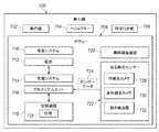
ここで図7に注目して、有利な実施形態に係る無人機のブロック図を描写する。無人機700は、図2におけるある数の無人機214の一実施構成の例である。いくつかの実施形態において、該無人機は、有人機または航空輸送手段以外の輸送手段、例えば、車、トラック、戦車などの地上輸送手段を含んでいてもよい。 Turning now to FIG. 7, a block diagram of a drone according to an advantageous embodiment is depicted. Unmanned
本説明例において、無人機700は、ある数の形態を取っていてもよい。例えば、無人機700は、例えば限定はされないが、飛行機702、ヘリコプター704、羽ばたき機706またはその他何らかの適切な種類の航空機であってもよい。 In this illustrative example, the
説明しているように、無人機700は、ボディー708、推進システム710、電池712、充電システム714、プロセッサユニット716、記憶装置718、無線通信装置720およびある数のセンサー722を含む。ボディー708は、無人機700の種々の構成部品を互いに関連付けることができる構造を提供する。例えば限定はされないが、ボディー708は、胴体であってもよい。さらに、ボディー708は、翼またはその他の種類の表面といった空気力学的表面を含んでいてもよい。 As described,
推進システム710は、空中で無人機700を移動させるよう構成されている。推進システム710は、例えば限定はされないが、プロペラまたはその他の種類の羽根を回転させるよう構成されている電気モーターであってもよい。その他の有利な実施形態において、推進システム710は、無人機700が羽ばたき機706の形態を取っているとき、ボディー708上の翼を動かすよう構成されていてもよい。電池712は、無人機700用の電気エネルギーを供給する。
充電システム714は、電池712と接続されており、かつ、電池712を充電ステーションにおいて再充電可能とする。充電システム714は、インダクティブ充電システムのためのインダクティブコイル、または、コンダクティブ充電システムのためのコンダクティブ接点を含んでいてもよい。いくつかの有利な実施形態において、充電システム714はまた、データの転送に用いられてもよい。一説明例として、充電システム714は、搬送周波数として変調された電荷をもたらしてもよい。この変調電荷は、電力の供給に加えてデータの転送を可能とする。
別の説明例として、充電システム714におけるコンダクティブ接点を用いて、データを転送してもよい。その他の有利な実施形態において、マイクロ波またはレーザを用いる充電システム714により無線で電力を供給してもよい。 As another illustrative example, data may be transferred using a conductive contact in charging
プロセッサユニット716は、これらの説明例において、任務のためのある数のプログラムを走らせる。記憶装置718は、センサー722により生成されるセンサーデータ724を保存してもよい。また、記憶装置718は、プロセッサユニット716により実行または走らされる任務726を保存してもよい。任務726は、例えば限定はされないが、プログラム、目的物の識別および/またはその他適切な種類の情報であってもよい。 The
無線通信装置720は、無人機700と図2における無人機ベースステーション200または遠隔地240のような遠隔地との間の通信を提供するよう構成されている。これらの説明例において、ある数のセンサー722は、例えば、可視光カメラ728、赤外線光カメラ730、動き検出器732、および/または、プロセッサユニット716による処理のためのセンサーデータ724の生成に用いられるその他適切な種類のセンサーのうちの少なくとも1つを含んでいてもよい。
図2〜図6における無人機ベースステーション200およびその構成要素ならびに図7における無人機700の説明は、種々の有利な実施形態を実施可能な手法に対する物理的または構造上の限定を暗示することを意図しているのではない。説明したものに加えて、かつ/または、これに代えてその他の構成要素を用いてもよい。いくつかの有利な実施形態では、いくつかの構成要素が不要であることもある。また、いくつかの機能的構成要素を示すために、ブロックが提示されている。種々の有利な実施形態において実施される際は、これらのブロックのうちの1つ以上を組み合わせ、かつ/または、種々のブロックに分割してもよい。 The description of the
例えば、いくつかの実施形態において、無人機ベースステーション200は、可動カバーシステム218を含んでいなくてもよい。その代わりに、ベイ216は、可動部品なしで環境224からの保護を提供するよう構成されていてもよい。例えば、ベイ216は、ある数の無人機214を環境224から保護するよう構成された開口を有するプラットフォーム202内の空洞であってもよい。また、いくつかの実施形態において、無人機700は、無線通信装置720を有していなくてもよい。その代わりに、有線接点を用いて、無人機700がプラットフォーム202上に着陸するときに、無人機700から無人機ベースステーション200へとデータを転送してもよい。 For example, in some embodiments, the
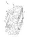
いくつかの実施形態において、輸送手段ベースステーション800は、輸送手段から電源、例えば、電池を自動的に取り外し、かつ/または、交換するためのアセンブリを含むよう適合されていてもよい。ここに説明する実施形態において、(1つまたは複数の)電源は、輸送手段上の電池受け部に選択可能に取り付けることができるモジュール式の台部900を含んでいてもよい。さらに、輸送手段ベースステーション800は、輸送手段から取り外された電池を再充電するよう適合されていてもよい。 In some embodiments, the
自動化電池保守のための輸送手段ベースステーション800の一実施形態は、図8A〜図8Cにおいて理解可能である。改良クワッドローターのような輸送手段は、傾斜着陸板812を含むプラットフォーム810上に設置されてもよく、かつ、1本以上の係止アーム814によりしっかりと下方に係止される。いくつかの実施形態において、プラットフォーム810の傾斜着陸板812は、重力により輸送手段がプラットフォーム上の所定の地点に位置付けられるように起伏がつけられている。輸送手段ベースステーション800は、第1電池ベイ820および第2電池ベイ840を有する。いくつかの実施形態において、電池ベイ820、840が存在し、これらの各々は、単一の電池を運搬および再充電できる4つの電池レセプタクルを有する回転ドラムを含む。輸送手段ベースステーション800は、人間の操作者の介入を必要とせずに電池を自動的に取替えて充電できる能力を提供する。 One embodiment of a
図8A〜図8Cおよび図9A〜図9Cは、展開された電池保守システムの3つのハードウェア構成要素、すなわち、電池台部(図9A)、電池受け部(図9B)および二重ドラム取替えステーション(図8A〜図8C)の模式図である。以下のセクションにおいて、これらの構成要素の各々をさらに詳細に取り上げる。 FIGS. 8A-8C and 9A-9C show three hardware components of the deployed battery maintenance system: a battery platform (FIG. 9A), a battery receptacle (FIG. 9B), and a dual drum replacement station. It is a schematic diagram of (FIG. 8A-FIG. 8C). Each of these components will be discussed in more detail in the following sections.
電池の迅速な取替えを可能とするために、電池台部900は、図9Aに示すように設計されてきた。台部900は、電池を収容可能な矩形角柱形フレーム920である。電力接点は、T字形レール912の両側の湾曲した銅製帯状片910を通じて設けられる。ギアラック914は、台部の底面に内臓されており、これにより、プラットフォーム800に見受けられるピニオンギアと噛合したときに直線運動が可能となる。 In order to enable quick replacement of the battery, the
図9Bは、実施形態にかかる電池受け部の模式図である。図9Bを参照して、いくつかの実施形態において、電池受け部940は、輸送手段に据え付けられていてもよい基部944を有するフレーム942を含む。フレームは、図9Cにおいて説明するように、電池台部を電池受け部に固定するために電池台部上のT字形レール912とかみ合う経路946を規定している。 FIG. 9B is a schematic view of the battery receiving portion according to the embodiment. With reference to FIG. 9B, in some embodiments, the
いくつかの実施形態において、電池取替え/充電プロセスは、搭載されているマイクロコントローラとコンピュータとの組み合わせを介して制御されてもよい。ステーション800は、ベイ内のベイピニオンモーターを制御するために各ドラムに対して1つ、両ドラムの充電プロセスを監視および制御するために充電ユニットに対して2つ、ならびに、内部および外部通信を管理し、かつ、中央モーター、係止アーム814および両ドラム回転を制御する1つの中央ユニットの合計5つのマイクロコントローラを含む。 In some embodiments, the battery replacement / charging process may be controlled through a combination of an on-board microcontroller and computer.
中央の着陸プラットフォーム810は、2つの電池ベイ820と840との間に置かれており、該電池ベイの各々は、回転ドラムとして実施されている。ドラムは、適切に同心上に位置合わせするために共通の金属軸の回りを回転する。2つのステッピングモーターは、着陸プラットフォーム810および電池受け部とのドラムの精密制御位置合わせのために用いられる。二重ドラム構造により、放電電池の除去と充電済み電池の装着とを同時に行うことが可能となる。 A
各電池ベイ820、840は、プリント配線基板(PCB)およびマイクロコントローラを含む。レセプタクルの内外への電池台部の直線運動は、ギアラック914にはめ込まれたピニオンモーターにより実現される。ベイの内側への台部の適切な設置のフィードバックは、各ベイに据え付けられたスイッチによりもたらされる。これらのスイッチから得られたフィードバックは、電池が正しく位置付けられたときに、ピニオンモーターを止めるために用いてもよい。これに加えて、電池を連続して充電し、かつ、電池電圧レベルを測定するために、電気的接続が設けられる。 Each
中央部分は、図8Cに示すように、傾斜着陸板812を収容している。電池受け部940の4本の脚部は、クワッドローターをその適切なx、yおよびz位置に支持する4つのドッキング点と一致する。これに加えて、サーボモーターにより駆動される銅製の上面を有する2本の独立した係止アーム814、816が、着陸したクワッドローターを把持し、その適切な位置合わせが確実に行われるようにし、クワッドローターをステーションにしっかりと係止し、電池交換の際にクワッドローターに陸電を供給する。着陸板の2つの端部上の2つの赤外線エミッタ/検出器センサーは、クワッドローターの下に電池台部が適切に位置合わせされると起動される。このフィードバックはまた、電池の取替え中に生じる可能性のあるピニオンモーター故障の検出にも用いられる。 As shown in FIG. 8C, the central portion accommodates an
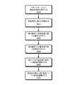
輸送手段ベースステーションの例のさまざまな構造的構成要素を説明してきたが、そのようなベースステーションを用いる方法をここで説明する。いくつかの実施形態において、ここに説明する輸送手段ベースステーションは、輸送手段上の電池を交換する方法を実施するために用いられてもよく、これを図10を参照しつつ説明する。 Having described various structural components of an example vehicle base station, a method of using such a base station will now be described. In some embodiments, the vehicle base station described herein may be used to implement a method for replacing a battery on the vehicle, which will be described with reference to FIG.
使用において、ハウジングのプラットフォーム上に輸送手段を位置付ける(動作1010)。UAVまたはMAVのような飛行輸送手段の場合、該飛行輸送手段は、プラットフォーム上に直接着陸させてもよい。あるいは、該飛行輸送手段は、別の場所に着陸させて、プラットフォーム上に手作業で位置付けられてもよい。地上輸送手段の場合、該輸送手段は、プラットフォーム上へ直接運転されても、プラットフォーム付近で運転され、次いで、プラットフォーム上に手作業で位置付けられてもよい。 In use, the vehicle is positioned on the housing platform (operation 1010). In the case of a flight vehicle such as UAV or MAV, the flight vehicle may land directly on the platform. Alternatively, the flight vehicle may be landed elsewhere and manually positioned on the platform. In the case of ground transportation means, the transportation means may be driven directly on the platform or operated near the platform and then manually positioned on the platform.
輸送手段がプラットフォーム上に位置付けられると、位置合わせアセンブリを起動して、プラットフォーム上で輸送手段を位置合わせしてもよい。図8A〜図8Cにおいて描写されている実施形態において、1つ以上の係止アーム814を起動して、プラットフォーム上で輸送手段を位置付け、かつ、固定してもよい。いくつかの実施形態において、係止アーム814は、輸送手段がプラットフォーム上にドッキングされたとき、輸送手段に電力を供給するために電源と結合されており、その結果、電池入れ替えプロセス中に輸送手段が連続的に電力供給される(動作1015)。 Once the vehicle is positioned on the platform, the alignment assembly may be activated to align the vehicle on the platform. In the embodiment depicted in FIGS. 8A-8C, one or more locking
動作1020において、第1電池ドッキングステーションを輸送手段と結合されている電池受け部と位置合わせし、動作1025において、第2電池ドッキングステーションを電池受け部と位置合わせする。図8A〜図8Cにおいて描写した実施形態において、充電済み電池が受け部と位置合わせされるように、第1電池ベイを前方へ移動させてもよく、かつ、空のドッキングステーションが受け部と位置合わせされるように、第2電池ベイを前方へ移動させてもよい。 In act 1020, the first battery docking station is aligned with the battery receiver coupled to the vehicle, and in
動作1030において、第1電池ベイ内のドッキングステーションから受け部内へと電池を摺動させる。図9A〜図9Cを参照しつつ説明したように電池が電池台部内に収容されている実施形態において、電池交換アセンブリは、第1電池ベイから電池受け部における位置内へ電池台部を摺動させる。第1電池ベイからの電池台部は、電池受け部内の電池台部を変位させ、これにより、台部において固定されていた電池を第2電池ベイにおける台部の外へ、かつ、空の電池ドッキングステーション内へ摺動させる(動作1035)。 In act 1030, the battery is slid from the docking station in the first battery bay into the receptacle. In the embodiment in which the battery is housed in the battery pedestal as described with reference to FIGS. 9A-9C, the battery replacement assembly slides the battery pedestal from the first battery bay into a position in the battery receiving part. Let The battery pedestal from the first battery bay displaces the battery pedestal in the battery receiving part, so that the battery fixed on the pedestal is moved out of the pedestal in the second battery bay and is empty. Slide into the docking station (operation 1035).
図および本文では、一側面において、輸送手段が位置付けられていてもよいプラットフォームと、プラットフォームの第1の側に位置している第1電池ベイ820と、輸送手段から電池712を取り除き、電池712を新たな電池712と交換する電池交換アセンブリと、輸送手段がプラットフォーム上に位置付けられている間に輸送手段に電力を供給するよう適合されている電源と、を含む輸送手段ベースステーションが開示されている。一変形例において、輸送手段ベースステーションは、第1の側とは反対のプラットフォームの第2の側に位置している第2電池ベイ840をさらに含む。別の変形例において、輸送手段ベースステーションは、電池交換アセンブリが、第1電池ベイ820から輸送手段に結合されている電池受け部940上へと電池712を摺動させ、輸送手段に結合されている電池受け部940から第2電池ベイ840上へと電池712を摺動させることを含む。さらに別の変形例において、輸送手段ベースステーションは、重力により輸送手段がプラットフォーム上の所定の地点に位置付けられるようにプラットフォームに起伏が付いていることを含む。 In the figure and text, in one aspect, the platform on which the vehicle may be located, the
一例において、輸送手段ベースステーションは、輸送手段をプラットフォームに係止する少なくとも1本の係止アーム814、816をさらに含み、該少なくとも1本の係止アーム814、816は、電源から輸送手段へと電力を供給する少なくとも1つの電力接点を含む。別の例において、第1電池ベイ820および第2電池ベイ840は、各々が、電池712を収容するための回転ドラムを含む。 In one example, the vehicle base station further includes at least one
一側面において、輸送手段に据え付け可能な基部944および基部944に結合されている経路を有する第1フレーム942を含む電池受け部940と、1つ以上の電池を保持することができる第2フレーム942、第2フレーム942上に据え付けられており、かつ、電池受け部フレーム942の基部944に結合されている経路にはめ込まれるよう適合されているレール912を含む電池台部900と、輸送手段を位置付けてもよいプラットフォーム、プラットフォームの第1の側に位置している第1電池ベイ820、第1の側とは反対のプラットフォームの第2の側に位置している第2電池ベイ840、輸送手段から電池712を取り除き、電池712を新たな電池712と交換する電池交換アセンブリ、および、輸送手段をプラットフォーム上に位置付けている間に輸送手段に電力を供給するよう適合されている電源を含む輸送手段ベースステーションと、を含むシステムが開示されている。 In one aspect, a base 944 mountable to the vehicle and a
一変形例において、該システムは、電池台部900が、レール上に少なくとも1つの電気接点を含み、かつ、経路が、電池台部900が電池受け部940にはめ込まれているときにレール912上の電気接点と結合するよう位置決めされている電気接点を含むことを含む。別の変形例において、該システムは、電池交換アセンブリが、第1電池ベイ820から輸送手段に結合されている電池受け部940上へと第1電池712を摺動させ、輸送手段に結合されている電池受け部940から第2電池ベイ840上へと第2電池712を摺動させることを含む。さらに別の変形例において、該システムは、電池交換アセンブリが、第1電池ベイ820から電池受け部940内へと第1電池712を収容する第1電池台部900を駆動し、かつ、第1電池台部900が、第2電池台部900を変位させることを含む。 In one variation, the system includes a
一例において、該システムは、第1電池712が電池受け部940から切断される前に、第2電池712が輸送手段に電力を供給することを含む。別の例において、該システムは、輸送手段をプラットフォームに係止する少なくとも1本の係止アーム814、816をさらに含み、係止アーム814、816が、電源から輸送手段へと電力を供給する少なくとも1つの電力接点を含む。さらに別の例において、該システムは、第1電池ベイ820および第2電池ベイ840は、各々が、複数の電池を保持することができる回転ドラムを含むことを含む。さらに別の例において、該システムは、第1電池ベイ820および第2電池ベイ840内に保存されている1つ以上の電池を充電するために電力を供給する、第1電池ベイ820および第2電池ベイ840に結合されている電源をさらに含む。 In one example, the system includes the
一側面において、輸送手段ベースステーションのプラットフォーム上に輸送手段を位置付けること、輸送手段が輸送手段ベースステーション上に位置付けられている間に輸送手段に連続的に電力を供給すること、充電済み電池712を含む第1電池ベイ820を輸送手段に結合されている電池受け部940の第1の側に位置合わせすること、空の第2電池ベイ840を第1の側と反対の電池受け部940の第2の側に位置合わせすること、第1電池ベイ820から輸送手段に結合されている電池受け部940上へと第1電池712を摺動させること、および、輸送手段に結合されている電池受け部940から第2電池ベイ840上へと第2電池712を摺動させること、を含む、輸送手段上の電池712を交換する方法を開示する。 In one aspect, positioning the vehicle on the platform of the vehicle base station, continuously supplying power to the vehicle while the vehicle is positioned on the vehicle base station, charging the charged
一変形例において、該方法には、第1電池ドッキングステーションから輸送手段に結合されている電池受け部940上へと第1電池712を摺動させることが、第1電池台部900が第2電池712を収容している第2電池712台部を変位させるように、第1電池ベイ820から電池受け部940内へと第1電池を収容している第1電池台部を摺動させることを含むことが挙げられる。別の変形例において、該方法は、第1電池712を電池受け部940から切断する前に、第2電池712が輸送手段に電力を供給することを含む。 In one variation, the method includes sliding the
さらに別の変形例において、該方法は、輸送手段が輸送手段ベースステーション上に位置付けられている間に輸送手段に連続的に電力を供給することが、輸送手段を係止する少なくとも1本の係止アーム814、816をプラットフォームに結合させることを含み、係止アーム814、816が輸送手段に電力を供給する少なくとも1つの電力接点を含むことを含む。一例において、該方法は、第1電池ベイ820および第2電池ベイ840は、各々が、複数の電池を保持することができる回転ドラムを含み、かつ、第1電池ベイ820および第2電池ベイ840を電池受け部940と位置合わせするために回転ドラムを回転させることを含む。 In yet another variation, the method includes providing at least one engagement for continuously supplying power to the vehicle while the vehicle is positioned on the vehicle base station. Coupling the
したがって、ここに説明したのは、輸送手段装着ステーションおよび輸送手段装着ステーションを用いるための関連した方法の例示的な実施形態である。いくつかの実施形態において、該輸送手段装着ステーションは、ペイロードを運搬している輸送手段を位置付けてもよい少なくとも1つのプラットフォームを規定するハウジングを含む。輸送手段ドッキングアセンブリは、プラットフォーム上の輸送手段をドッキングおよび固定する。電池交換アセンブリは、輸送手段からペイロードを取り除き、新たなペイロードと交換する。 Accordingly, described herein are exemplary embodiments of a vehicle mounting station and related methods for using the vehicle mounting station. In some embodiments, the vehicle loading station includes a housing defining at least one platform on which a vehicle carrying a payload may be located. The vehicle docking assembly docks and secures the vehicle on the platform. The battery replacement assembly removes the payload from the vehicle and replaces it with a new payload.
明細書における「一実施形態」または「いくつかの実施形態」への言及は、該実施形態との関連において説明する特定の特徴、構造または特性が少なくとも1つの実施構成に含まれていることを意味する。明細書中のさまざまな箇所における「一実施形態において」という句の登場は、すべてが同じ実施形態に言及していても、していなくてもよい。 References to “one embodiment” or “some embodiments” in this specification indicate that the particular feature, structure, or characteristic described in connection with the embodiment is included in at least one implementation. means. The appearances of the phrase “in one embodiment” in various places in the specification may or may not all refer to the same embodiment.
実施形態は、構造的特徴および/または方法論的行為に特有の言語で説明してきたが、クレームされている主題は、説明した特定の特徴または行為に限定されてはならないことは理解されたい。むしろ、クレームされている主題を実施する形態の実例として特定の特徴および行為が開示されている。 Although embodiments have been described in language specific to structural features and / or methodological acts, it is to be understood that the claimed subject matter should not be limited to the specific features or acts described. Rather, the specific features and acts are disclosed as example forms of implementing the claimed subject matter.
100 無人機環境
102、104、106 無人機ベースステーション
108 屋上
110 建物
112 町
114 輸送手段
116 電力線
118、120、122、124、126、128、130、132、134、136、138 無人機
140 車道
200 無人機ベースステーション
202 プラットフォーム
204 電池システム
206 発電システム
208 ある数の充電ステーション
210 制御装置
212 センサーシステム
214 ある数の無人機
216 ベイ
218 可動カバーシステム
220 開位置
222 閉位置
224 環境
226 電気エネルギー
236 センサーデータ
238 情報
240 遠隔地
242 任務
244 液体燃料補給システム
246 液体燃料タンク
248 ポンプ
248 センサーデータ
250 コマンド
300 データ処理システム
302 通信機構
304 プロセッサユニット
306 メモリ
308 固定記憶域
310 通信ユニット
312 入出力ユニット
314 表示部
316 記憶装置
318 プログラムコード
320 コンピュータ読み取り可能な媒体
322 コンピュータプログラム製品
324 コンピュータ読み取り可能な記憶媒体
326 コンピュータ読み取り可能な信号媒体
400 発電システム
401 電気エネルギー
402 エネルギーハーベスティングシステム
404 太陽光発電ユニット
406 誘導発電ユニット
408 風力発電ユニット
410 放射性同位元素熱電発電ユニット
412 電力変換装置
416 太陽エネルギーセル
500 センサーシステム
501 センサーデータ
502 カメラシステム
504 全地球測位システムユニット
506 気象センサー
508 動き検出器
510 ある数のカメラ
512 可視光カメラ
514 赤外線カメラ
518 画像データ
520 位置情報
522 時刻情報
524 気象データ
526 動きデータ
600 充電ステーション
602 インダクティブ充電システム
604 コンダクティブ充電システム
606 磁界
608 接点
610 電流
700 無人機
702 飛行機
704 ヘリコプター
706 羽ばたき機
708 ボディー
710 推進システム
712 電池
714 充電システム
716 プロセッサユニット
718 記憶装置
720 無線通信装置
722 ある数のセンサー
724 センサーデータ
726 任務
728 可視光カメラ
730 赤外線光カメラ
732 動き検出器
800 輸送手段ベースステーション
810 プラットフォーム
812 傾斜着陸板
814、816 係止アーム
820 第1電池ベイ
840 第2電池ベイ
870 電源
900 台部
910 銅製帯状片
912 T字形レール
914 ギアラック
920 矩形角柱形フレーム
940 電池受け部
944 基部
942 フレーム
946 経路100 Unmanned Aircraft Environment 102, 104, 106 Unmanned Aircraft Base Station 108 Rooftop 110 Building 112 Town 114 Transport Means 116 Power Line 118, 120, 122, 124, 126, 128, 130, 132, 134, 136, 138 Unmanned Aircraft 140 Roadway 200 Drone base station 202 platform 204 battery system 206 power generation system 208 number of charging stations 210 controller 212 sensor system 214 number of drones 216 bay 218 movable cover system 220 open position 222 closed position 224 environment 226 electrical energy 236 sensor data 238 Information 240 Remote 242 Mission 244 Liquid Refueling System 246 Liquid Fuel Tank 248 Pump 248 Sensor Data 250 Command 300 Data Processing System 302 Communication Mechanism 304 Processor Unit 306 Memory 308 Fixed Storage Area 310 Communication Unit 312 Input / Output Unit 314 Display Unit 316 Storage Device 318 Program Code 320 Computer-readable Medium 322 Computer Program Product 324 Computer-readable Storage Medium 326 Computer-readable signal medium 400 Power generation system 401 Electric energy 402 Energy harvesting system 404 Solar power generation unit 406 Induction power generation unit 408 Wind power generation unit 410 Radioisotope thermoelectric power generation unit 412 Power converter 416 Solar energy cell 500 Sensor system 501 Sensor Data 502 Camera system 504 Global positioning system Unit 506 weather sensor 508 motion detector 510 a number of cameras 512 visible light camera 514 infrared camera 518 image data 520 position information 522 time information 524 weather data 526 motion data 600 charging station 602 inductive charging system 604 conductive charging system 606 magnetic field 608 contact 610 Current 700 Unmanned Aircraft 702 Airplane 704 Helicopter 706 Flapping Aircraft 708 Body 710 Propulsion System 712 Battery 714 Charging System 716 Processor Unit 718 Storage Device 720 Wireless Communication Device 722 Some Sensors 724 Sensor Data 726 Light Camera 728 Light Camera 728 Light 732 motion detector 800 vehicle base station 810 platform Form 812 Inclined landing plate 814, 816 Locking arm 820 First battery bay 840 Second battery bay 870 Power supply 900 Base portion 910 Copper strip 912 T-shaped rail 914 Gear rack 920 Rectangular prismatic frame 940 Battery receiving portion 944 Base 942 Frame 946 Route
Claims (13)
Translated fromJapaneseを含む電池受け部(940)と、
1つ以上の電池を保持することができる第2フレーム(942)、
第2フレーム(942)上に据え付けられており、かつ、電池受け部フレーム(942)の基部(944)に結合されている経路にはめ込まれるよう適合されているレール(912)
を含む電池台部(900)と、
輸送手段を位置付けてもよいプラットフォーム、
プラットフォームの第1の側に位置している第1電池ベイ(820)、
第1の側とは反対のプラットフォームの第2の側に位置している第2電池ベイ(840)、
輸送手段から電池(712)を取り除き、電池(712)を新たな電池(712)と交換する電池交換アセンブリ、および、
輸送手段をプラットフォーム上に位置付けている間に輸送手段に電力を供給するよう適合されている電源
を含む輸送手段ベースステーションと、
を含むシステム。A first frame (942) having a base (944) mountable to the vehicle and a path coupled to the base (944)
A battery receiver (940) including:
A second frame (942) capable of holding one or more batteries,
A rail (912) mounted on the second frame (942) and adapted to fit into a path coupled to the base (944) of the battery receiver frame (942).
A battery stand (900) including:
A platform on which the vehicle may be located,
A first battery bay (820) located on the first side of the platform;
A second battery bay (840) located on the second side of the platform opposite the first side;
A battery replacement assembly for removing the battery (712) from the vehicle and replacing the battery (712) with a new battery (712); and
A vehicle base station including a power source adapted to supply power to the vehicle while the vehicle is positioned on the platform;
Including system.
経路(946)が、電池台部(900)が電池受け部(940)にはめ込まれているときにレール(912)上の電気接点と結合するよう位置決めされている電気接点を含む
請求項1に記載のシステム。The battery platform (900) includes at least one electrical contact on the rail; and
The path (946) includes electrical contacts positioned to mate with electrical contacts on the rail (912) when the battery platform (900) is fitted into the battery receptacle (940). The described system.
請求項1または請求項2のいずれか一項に記載のシステム。A battery replacement assembly is coupled to the vehicle by the battery replacement assembly sliding the first battery (712) from the first battery bay (820) onto the battery receiver (940) coupled to the vehicle. The system of any one of claims 1 or 2, wherein the second battery (712) is slid from (940) onto the second battery bay (840).
第1電池台部(900)が、第2電池台部(900)を変位させる
請求項3に記載のシステム。A battery replacement assembly drives a first battery platform (900) that houses the first battery (712) from the first battery bay (820) into the battery receptacle (940); and
The system according to claim 3, wherein the first battery base (900) displaces the second battery base (900).
請求項1に記載のシステム。The system of claim 1, wherein the first battery bay (820) and the second battery bay (840) each include a rotating drum capable of holding a plurality of batteries.
輸送手段ベースステーションのプラットフォーム上に輸送手段を位置付けること、
輸送手段が輸送手段ベースステーション上に位置付けられている間に輸送手段に連続的に電力を供給すること、
充電済み電池(712)を含む第1電池ベイ(820)を輸送手段に結合されている電池受け部(940)の第1の側に位置合わせすること、
空の第2電池ベイ(840)を第1の側と反対の電池受け部(940)の第2の側に位置合わせすること、
第1電池ベイ(820)から輸送手段に結合されている電池受け部(940)上へと第1電池(712)を摺動させること、および、
輸送手段に結合されている電池受け部(940)から第2電池ベイ(840)上へと第2電池(712)を摺動させること、
を含む方法。A method of replacing a battery (712) on a vehicle,
Positioning the vehicle on the platform of the vehicle base station;
Continuously supplying power to the vehicle while the vehicle is positioned on the vehicle base station;
Aligning a first battery bay (820) containing a charged battery (712) with a first side of a battery receptacle (940) coupled to the vehicle;
Aligning the empty second battery bay (840) with the second side of the battery receptacle (940) opposite the first side;
Sliding the first battery (712) from the first battery bay (820) onto the battery receptacle (940) coupled to the vehicle; and
Sliding the second battery (712) from the battery receptacle (940) coupled to the transport means onto the second battery bay (840);
Including methods.
Applications Claiming Priority (4)
| Application Number | Priority Date | Filing Date | Title |
|---|---|---|---|
| US201261617312P | 2012-03-29 | 2012-03-29 | |
| US61/617,312 | 2012-03-29 | ||
| US13/663,608US8862288B2 (en) | 2010-05-18 | 2012-10-30 | Vehicle base station |
| US13/663,608 | 2012-10-30 |
Publications (2)
| Publication Number | Publication Date |
|---|---|
| JP2013203394Atrue JP2013203394A (en) | 2013-10-07 |
| JP6180765B2 JP6180765B2 (en) | 2017-08-16 |
Family
ID=47998308
Family Applications (1)
| Application Number | Title | Priority Date | Filing Date |
|---|---|---|---|
| JP2013058590AActiveJP6180765B2 (en) | 2012-03-29 | 2013-03-21 | Transportation base station |
Country Status (2)
| Country | Link |
|---|---|
| EP (1) | EP2644438B1 (en) |
| JP (1) | JP6180765B2 (en) |
Cited By (28)
| Publication number | Priority date | Publication date | Assignee | Title |
|---|---|---|---|---|
| JP2015189435A (en)* | 2014-03-28 | 2015-11-02 | 三菱重工業株式会社 | Unmanned machine mounting part and modular armoring |
| JP2016531797A (en)* | 2014-07-31 | 2016-10-13 | エスゼット ディージェイアイ テクノロジー カンパニー リミテッドSz Dji Technology Co.,Ltd | Unmanned aircraft dock and battery replacement device |
| JP2016215796A (en)* | 2015-05-19 | 2016-12-22 | 株式会社アドテックス | Unmanned flying vehicle and control system therefor |
| JP2017514755A (en)* | 2014-05-01 | 2017-06-08 | アラカイ テクノロジーズ コーポレーション | Clean fuel electric multi-rotor aircraft for personal air transport and manned or unmanned operation |
| JP2017518917A (en)* | 2014-07-31 | 2017-07-13 | エスゼット ディージェイアイ テクノロジー カンパニー リミテッドSz Dji Technology Co.,Ltd | Unmanned aerial vehicle base station and method |
| JP2017528354A (en)* | 2014-08-08 | 2017-09-28 | エスゼット ディージェイアイ テクノロジー カンパニー リミテッドSz Dji Technology Co.,Ltd | UAV energy exchange station |
| JP2017530900A (en)* | 2014-11-21 | 2017-10-19 | エスゼット ディージェイアイ テクノロジー カンパニー リミテッドSz Dji Technology Co.,Ltd | Load or battery management method |
| JP2017534513A (en)* | 2014-10-02 | 2017-11-24 | スウィフト・エンジニアリング・インコーポレーテッド | Portable ground station for unmanned aerial vehicles |
| JP2018516024A (en)* | 2015-03-12 | 2018-06-14 | ナイチンゲール インテリジェント システムズ | Automatic drone system |
| JP2018100088A (en)* | 2018-02-02 | 2018-06-28 | エスゼット ディージェイアイ テクノロジー カンパニー リミテッドSz Dji Technology Co.,Ltd | Method of supplying energy to uav, and uav |
| JP2019502594A (en)* | 2015-12-21 | 2019-01-31 | エアーズコルト リミテッド | Autonomous docking station for drones |
| JP2019104491A (en)* | 2019-02-14 | 2019-06-27 | エスゼット ディージェイアイ テクノロジー カンパニー リミテッドSz Dji Technology Co.,Ltd | Positioning mechanism, uav dock using the same and uav supply method |
| JP2019172255A (en)* | 2019-06-05 | 2019-10-10 | エスゼット ディージェイアイ テクノロジー カンパニー リミテッドSz Dji Technology Co.,Ltd | Method and device for supplying energy to uav |
| US10611252B2 (en) | 2014-08-08 | 2020-04-07 | SZ DJI Technology Co., Ltd. | Systems and methods for UAV battery power backup |
| JP2021011386A (en)* | 2018-02-08 | 2021-02-04 | ビタ インクリナータ テクノロジーズ インコーポレーテッドVita Inclinata Technologies, Inc. | Suspended load stabilization system and method |
| US11091043B2 (en) | 2014-08-08 | 2021-08-17 | SZ DJI Technology Co., Ltd. | Multi-zone battery exchange system |
| JP2021164172A (en)* | 2020-03-30 | 2021-10-11 | 株式会社Gsユアサ | Charger for unmanned aircraft and charging system |
| EP3892548A1 (en) | 2020-04-10 | 2021-10-13 | Aqprim | Urban building adapted to aerial drones for transporting passengers and parcels |
| JP2022097373A (en)* | 2020-12-18 | 2022-06-30 | 東友科技股▲ふん▼有限公司 | Drone and its battery replacement system |
| US11524796B2 (en) | 2014-11-19 | 2022-12-13 | SZ DJI Technology Co., Ltd. | Positioning mechanism, UAV dock using same, and UAV replenishment method |
| US11620597B1 (en) | 2022-04-29 | 2023-04-04 | Vita Inclinata Technologies, Inc. | Machine learning real property object detection and analysis apparatus, system, and method |
| KR20230052664A (en)* | 2021-10-13 | 2023-04-20 | 한화시스템 주식회사 | Battery charging system and method using energy harvesting technology and wireless charging technology, and battery charging station operating system and method using the same |
| US11746951B2 (en) | 2019-02-26 | 2023-09-05 | Vita Inclinata Ip Holdings Llc | Cable deployment apparatus, system, and methods for suspended load control equipment |
| US11834174B2 (en) | 2018-02-08 | 2023-12-05 | Vita Inclinata Ip Holdings Llc | Control of drone-load system method, system, and apparatus |
| US11834305B1 (en) | 2019-04-12 | 2023-12-05 | Vita Inclinata Ip Holdings Llc | Apparatus, system, and method to control torque or lateral thrust applied to a load suspended on a suspension cable |
| US11926415B2 (en) | 2018-02-08 | 2024-03-12 | Vita Inclinata Ip Holdings Llc | Long line loiter apparatus, system, and method |
| US12145822B2 (en) | 2018-02-08 | 2024-11-19 | Vita Inclinata Ip Holdings Llc | Integrated and modular suspended load control apparatuses, systems, and methods |
| US12246952B2 (en) | 2018-02-08 | 2025-03-11 | Vita Inclintata IP Holdings LLC | Hoist and deployable equipment apparatus, system, and method |
Families Citing this family (24)
| Publication number | Priority date | Publication date | Assignee | Title |
|---|---|---|---|---|
| WO2021183576A1 (en)* | 2020-03-13 | 2021-09-16 | Getman Anya L | Methods and devices for electrically insulating a power line |
| DE102014003417B4 (en)* | 2014-03-13 | 2020-05-14 | Uwe Gaßmann | Charging or battery changing station for aircraft |
| GB201409654D0 (en)* | 2014-05-30 | 2014-07-16 | Geola Technologies Ltd | Charging and re-provisioning station for electric and hybrid UAVx |
| DE102015205092A1 (en)* | 2015-03-20 | 2016-09-22 | Siemens Aktiengesellschaft | Drone base station for public space and a correspondingly extended traffic signal system |
| US9776717B2 (en)* | 2015-10-02 | 2017-10-03 | The Boeing Company | Aerial agricultural management system |
| CN106230125B (en)* | 2016-08-31 | 2018-09-28 | 国网湖北省电力有限公司武汉供电公司 | A kind of online electricity getting device of unmanned aerial vehicle |
| ES2660486B1 (en)* | 2016-09-22 | 2019-01-02 | Picazo Aroca Jose Antonio | Wireless charging service station for Unmanned Aircraft |
| DE102017127027B4 (en) | 2017-02-21 | 2024-02-01 | Thomas Weimer | Ground station for a battery-operated unmanned aerial vehicle and battery-operated unmanned aerial vehicle |
| CN108820237A (en)* | 2018-05-31 | 2018-11-16 | 智飞智能装备科技东台有限公司 | A kind of photovoltaic charged base station for unmanned plane |
| CN109080477A (en)* | 2018-07-28 | 2018-12-25 | 深圳市旭发智能科技有限公司 | A kind of unmanned plane battery altering management method and base station |
| CN108910069A (en)* | 2018-08-14 | 2018-11-30 | 深圳市烽焌信息科技有限公司 | A kind of battery configuration method of unmanned plane continuation of the journey base station |
| CN109080841A (en)* | 2018-08-14 | 2018-12-25 | 深圳市烽焌信息科技有限公司 | A kind of unmanned plane continuation of the journey base station |
| CN109835204A (en)* | 2019-01-25 | 2019-06-04 | 陶银霞 | A kind of convenient mobile charging device that battery is carried of unmanned plane |
| DE102019109127B4 (en)* | 2019-04-08 | 2023-09-21 | Thomas Weimer | Drone-based aerial and collision monitoring system |
| US10717528B1 (en)* | 2019-10-03 | 2020-07-21 | Trung Vo Tran | Automatic flying delivery drone in precalculated flight routes and method for delivering merchandises |
| CN110937115A (en)* | 2019-11-24 | 2020-03-31 | 浙江万物科技有限公司 | Unmanned aerial vehicle mounting equipment |
| RU2734680C1 (en)* | 2020-02-11 | 2020-10-21 | Публичное акционерное общество "Ракетно-космическая корпорация "Энергия" имени С.П. Королева" | Quadcopter |
| CA3082217A1 (en)* | 2020-06-03 | 2021-12-03 | Skyyfish Llc | Battery exchange and charging system for drones |
| US12100853B2 (en) | 2021-04-06 | 2024-09-24 | United Parcel Service Of America, Inc. | Pneumatic delivery system and method for use with unmanned vehicle systems |
| US11400829B1 (en) | 2021-07-13 | 2022-08-02 | Popion Mobility Inc. | Methods and systems for battery-vehicle interface solutions for supporting use of swappable batteries in electric vehicles |
| CA3227384A1 (en) | 2021-08-26 | 2023-03-02 | Julian Bell | Locking mechanism and container for delivering items |
| WO2023028334A1 (en)* | 2021-08-26 | 2023-03-02 | United Parcel Service Of America, Inc. | Battery exchange system for unmanned vehicles |
| US12080907B2 (en) | 2021-08-26 | 2024-09-03 | United Parcel Service Of America, Inc. | Locking mechanism and container for delivering items |
| DE102022106805A1 (en) | 2022-03-23 | 2023-09-28 | Nicolas Goldberg | Arrangement for automated loading and unloading of vehicles |
Citations (9)
| Publication number | Priority date | Publication date | Assignee | Title |
|---|---|---|---|---|
| JPH0717265A (en)* | 1993-07-06 | 1995-01-20 | Nippon Home Keizai Kenkyusho:Kk | Vehicle mounting device for secondary battery for electric vehicle power |
| JPH0747842A (en)* | 1993-02-23 | 1995-02-21 | Kokuritsu Kankyo Kenkyusho | Body for electric automobile |
| JPH11115504A (en)* | 1997-10-21 | 1999-04-27 | Fuji Heavy Ind Ltd | Battery mounting structure for automobile |
| JP2003143714A (en)* | 2001-11-02 | 2003-05-16 | Komatsu Forklift Co Ltd | Battery replacement device for electric vehicle |
| JP2003226142A (en)* | 2002-02-01 | 2003-08-12 | Seiko Epson Corp | Battery replacement method for electric vehicle and battery mounting structure for electric vehicle |
| US20070113921A1 (en)* | 2005-11-04 | 2007-05-24 | Capizzo Peter D | System for replenishing energy sources onboard different types of automotive vehicles |
| JP2008297106A (en)* | 2007-06-04 | 2008-12-11 | Tcm Corp | Battery storing device of industrial vehicle |
| WO2011010651A1 (en)* | 2009-07-22 | 2011-01-27 | 株式会社東京アールアンドデー | Electric vehicle battery changing system, electric vehicle, battery device and stand for battery changing |
| JP2011152885A (en)* | 2010-01-28 | 2011-08-11 | E-1 Technology Llc | Vehicle rotating device |
Family Cites Families (5)
| Publication number | Priority date | Publication date | Assignee | Title |
|---|---|---|---|---|
| GB2277067A (en)* | 1993-04-13 | 1994-10-19 | William Chilton | Station for changing and recharging batteries for electric cars |
| US5927938A (en)* | 1994-01-06 | 1999-07-27 | Unlimited Range Electric Car Systems Company | Battery charging and transfer system for electrically powered vehicles |
| US5612606A (en)* | 1994-09-15 | 1997-03-18 | David C. Guimarin | Battery exchange system for electric vehicles |
| US7637196B2 (en)* | 2000-11-30 | 2009-12-29 | Lockheed-Martin Corporation | System and method for detecting objects and substances |
| US7431339B2 (en)* | 2004-09-03 | 2008-10-07 | Nissan Technical Center North America, Inc. | Vehicle structure |
- 2013
- 2013-03-21JPJP2013058590Apatent/JP6180765B2/enactiveActive
- 2013-03-28EPEP13161788.8Apatent/EP2644438B1/enactiveActive
Patent Citations (9)
| Publication number | Priority date | Publication date | Assignee | Title |
|---|---|---|---|---|
| JPH0747842A (en)* | 1993-02-23 | 1995-02-21 | Kokuritsu Kankyo Kenkyusho | Body for electric automobile |
| JPH0717265A (en)* | 1993-07-06 | 1995-01-20 | Nippon Home Keizai Kenkyusho:Kk | Vehicle mounting device for secondary battery for electric vehicle power |
| JPH11115504A (en)* | 1997-10-21 | 1999-04-27 | Fuji Heavy Ind Ltd | Battery mounting structure for automobile |
| JP2003143714A (en)* | 2001-11-02 | 2003-05-16 | Komatsu Forklift Co Ltd | Battery replacement device for electric vehicle |
| JP2003226142A (en)* | 2002-02-01 | 2003-08-12 | Seiko Epson Corp | Battery replacement method for electric vehicle and battery mounting structure for electric vehicle |
| US20070113921A1 (en)* | 2005-11-04 | 2007-05-24 | Capizzo Peter D | System for replenishing energy sources onboard different types of automotive vehicles |
| JP2008297106A (en)* | 2007-06-04 | 2008-12-11 | Tcm Corp | Battery storing device of industrial vehicle |
| WO2011010651A1 (en)* | 2009-07-22 | 2011-01-27 | 株式会社東京アールアンドデー | Electric vehicle battery changing system, electric vehicle, battery device and stand for battery changing |
| JP2011152885A (en)* | 2010-01-28 | 2011-08-11 | E-1 Technology Llc | Vehicle rotating device |
Cited By (45)
| Publication number | Priority date | Publication date | Assignee | Title |
|---|---|---|---|---|
| JP2015189435A (en)* | 2014-03-28 | 2015-11-02 | 三菱重工業株式会社 | Unmanned machine mounting part and modular armoring |
| US9952022B2 (en) | 2014-03-28 | 2018-04-24 | Mitsubishi Heavy Industries, Ltd. | Modularized armor structure with unmanned aerial vehicle loaded and armored vehicle using the same |
| JP2017514755A (en)* | 2014-05-01 | 2017-06-08 | アラカイ テクノロジーズ コーポレーション | Clean fuel electric multi-rotor aircraft for personal air transport and manned or unmanned operation |
| US11390374B2 (en) | 2014-05-01 | 2022-07-19 | Alakai Technologies Corporation | Clean fuel electric aircraft for personal air transportation and manned or unmanned operation |
| US10370088B2 (en) | 2014-05-01 | 2019-08-06 | Alakai Technologies Corporation | Clean fuel electric multirotor aircraft for personal air transportation and manned or unmanned operation |
| JP2016531797A (en)* | 2014-07-31 | 2016-10-13 | エスゼット ディージェイアイ テクノロジー カンパニー リミテッドSz Dji Technology Co.,Ltd | Unmanned aircraft dock and battery replacement device |
| US10696185B2 (en) | 2014-07-31 | 2020-06-30 | SZ DJI Technology Co., Ltd. | Unmanned aerial vehicle dock and battery replacement device thereof |
| JP2017518917A (en)* | 2014-07-31 | 2017-07-13 | エスゼット ディージェイアイ テクノロジー カンパニー リミテッドSz Dji Technology Co.,Ltd | Unmanned aerial vehicle base station and method |
| US10369975B2 (en) | 2014-07-31 | 2019-08-06 | SZ DJI Technology Co., Ltd. | Unmanned aerial vehicle base station system and method |
| US10259332B2 (en) | 2014-07-31 | 2019-04-16 | SZ DJI Technology Co., Ltd. | Unmanned aerial vehicle dock and battery replacement device thereof |
| US11708003B2 (en) | 2014-07-31 | 2023-07-25 | SZ DJI Technology Co., Ltd. | Unmanned aerial vehicle base station system and method |
| JP2017528354A (en)* | 2014-08-08 | 2017-09-28 | エスゼット ディージェイアイ テクノロジー カンパニー リミテッドSz Dji Technology Co.,Ltd | UAV energy exchange station |
| US10363826B2 (en) | 2014-08-08 | 2019-07-30 | SZ DJI Technology Co., Ltd. | Systems and methods for UAV battery exchange |
| US10611252B2 (en) | 2014-08-08 | 2020-04-07 | SZ DJI Technology Co., Ltd. | Systems and methods for UAV battery power backup |
| US11332033B2 (en) | 2014-08-08 | 2022-05-17 | SZ DJI Technology Co., Ltd. | Systems and methods for UAV battery exchange |
| US11091043B2 (en) | 2014-08-08 | 2021-08-17 | SZ DJI Technology Co., Ltd. | Multi-zone battery exchange system |
| JP2017534513A (en)* | 2014-10-02 | 2017-11-24 | スウィフト・エンジニアリング・インコーポレーテッド | Portable ground station for unmanned aerial vehicles |
| US11524796B2 (en) | 2014-11-19 | 2022-12-13 | SZ DJI Technology Co., Ltd. | Positioning mechanism, UAV dock using same, and UAV replenishment method |
| US10195952B2 (en) | 2014-11-21 | 2019-02-05 | SZ DJI Technology Co., Ltd. | System and method for managing unmanned aerial vehicles |
| JP2017530900A (en)* | 2014-11-21 | 2017-10-19 | エスゼット ディージェイアイ テクノロジー カンパニー リミテッドSz Dji Technology Co.,Ltd | Load or battery management method |
| JP2018516024A (en)* | 2015-03-12 | 2018-06-14 | ナイチンゲール インテリジェント システムズ | Automatic drone system |
| US11215986B2 (en) | 2015-03-12 | 2022-01-04 | Nightingale Intelligent Systems | Automated drone systems |
| JP2016215796A (en)* | 2015-05-19 | 2016-12-22 | 株式会社アドテックス | Unmanned flying vehicle and control system therefor |
| JP2019502594A (en)* | 2015-12-21 | 2019-01-31 | エアーズコルト リミテッド | Autonomous docking station for drones |
| JP2018100088A (en)* | 2018-02-02 | 2018-06-28 | エスゼット ディージェイアイ テクノロジー カンパニー リミテッドSz Dji Technology Co.,Ltd | Method of supplying energy to uav, and uav |
| US12246952B2 (en) | 2018-02-08 | 2025-03-11 | Vita Inclintata IP Holdings LLC | Hoist and deployable equipment apparatus, system, and method |
| US11926415B2 (en) | 2018-02-08 | 2024-03-12 | Vita Inclinata Ip Holdings Llc | Long line loiter apparatus, system, and method |
| US11834174B2 (en) | 2018-02-08 | 2023-12-05 | Vita Inclinata Ip Holdings Llc | Control of drone-load system method, system, and apparatus |
| JP2021011386A (en)* | 2018-02-08 | 2021-02-04 | ビタ インクリナータ テクノロジーズ インコーポレーテッドVita Inclinata Technologies, Inc. | Suspended load stabilization system and method |
| US12145822B2 (en) | 2018-02-08 | 2024-11-19 | Vita Inclinata Ip Holdings Llc | Integrated and modular suspended load control apparatuses, systems, and methods |
| JP7162908B2 (en) | 2018-02-08 | 2022-10-31 | ビタ インクリナータ テクノロジーズ インコーポレーテッド | Suspended load stabilization system and method |
| JP2019104491A (en)* | 2019-02-14 | 2019-06-27 | エスゼット ディージェイアイ テクノロジー カンパニー リミテッドSz Dji Technology Co.,Ltd | Positioning mechanism, uav dock using the same and uav supply method |
| US11746951B2 (en) | 2019-02-26 | 2023-09-05 | Vita Inclinata Ip Holdings Llc | Cable deployment apparatus, system, and methods for suspended load control equipment |
| US11834305B1 (en) | 2019-04-12 | 2023-12-05 | Vita Inclinata Ip Holdings Llc | Apparatus, system, and method to control torque or lateral thrust applied to a load suspended on a suspension cable |
| JP2019172255A (en)* | 2019-06-05 | 2019-10-10 | エスゼット ディージェイアイ テクノロジー カンパニー リミテッドSz Dji Technology Co.,Ltd | Method and device for supplying energy to uav |
| JP2021164172A (en)* | 2020-03-30 | 2021-10-11 | 株式会社Gsユアサ | Charger for unmanned aircraft and charging system |
| JP2024173959A (en)* | 2020-03-30 | 2024-12-13 | 株式会社Gsユアサ | Charging devices, charging systems, disaster support systems, transportation systems and pillars for unmanned aerial vehicles |
| JP7562973B2 (en) | 2020-03-30 | 2024-10-08 | 株式会社Gsユアサ | Charging device and charging system for unmanned aerial vehicles |
| EP3892548A1 (en) | 2020-04-10 | 2021-10-13 | Aqprim | Urban building adapted to aerial drones for transporting passengers and parcels |
| FR3109168A1 (en) | 2020-04-10 | 2021-10-15 | Aqprim | Urban building suitable for aerial drones for transporting passengers and parcels |
| JP7254135B2 (en) | 2020-12-18 | 2023-04-07 | 東友科技股▲ふん▼有限公司 | Drone and its battery exchange system |
| JP2022097373A (en)* | 2020-12-18 | 2022-06-30 | 東友科技股▲ふん▼有限公司 | Drone and its battery replacement system |
| KR20230052664A (en)* | 2021-10-13 | 2023-04-20 | 한화시스템 주식회사 | Battery charging system and method using energy harvesting technology and wireless charging technology, and battery charging station operating system and method using the same |
| KR102616730B1 (en)* | 2021-10-13 | 2023-12-21 | 한화시스템 주식회사 | Battery charging system and method using energy harvesting technology and wireless charging technology, and battery charging station operating system and method using the same |
| US11620597B1 (en) | 2022-04-29 | 2023-04-04 | Vita Inclinata Technologies, Inc. | Machine learning real property object detection and analysis apparatus, system, and method |
Also Published As
| Publication number | Publication date |
|---|---|
| EP2644438A3 (en) | 2018-01-03 |
| EP2644438A2 (en) | 2013-10-02 |
| EP2644438B1 (en) | 2019-02-13 |
| JP6180765B2 (en) | 2017-08-16 |
Similar Documents
| Publication | Publication Date | Title |
|---|---|---|
| JP6180765B2 (en) | Transportation base station | |
| US8862288B2 (en) | Vehicle base station | |
| US8899903B1 (en) | Vehicle base station | |
| US11332033B2 (en) | Systems and methods for UAV battery exchange | |
| US9678507B1 (en) | Autonomous infrastructure element survey systems and methods using UAV fleet deployment | |
| US9845020B2 (en) | Transportable ground station for an unmanned aerial vehicle | |
| US9868526B2 (en) | Airborne drone delivery network and method of operating same | |
| US8511606B1 (en) | Unmanned aerial vehicle base station | |
| EP3177531B1 (en) | Multi-zone battery exchange system for uav | |
| US10850866B2 (en) | Pod cover system for a vertical take-off and landing (VTOL) unmanned aerial vehicle (UAV) | |
| JP6395835B2 (en) | UAV battery power backup system and method | |
| US20170225802A1 (en) | Systems and methods for deployment and operation of vertical take-off and landing (vtol) unmanned aerial vehicles | |
| JP2018100088A (en) | Method of supplying energy to uav, and uav | |
| EP3826881A1 (en) | Recharging network for drones | |
| EP3956220B1 (en) | A uav carrier | |
| EP3969381B1 (en) | A system and method for drone release detection | |
| RU168376U1 (en) | SMALL UNMANNED AIRCRAFT | |
| Saad et al. | Vehicle base station | |
| Ngo et al. | Classification of robotic battery service systems for unmanned aerial vehicles | |
| TR201616642A2 (en) | Ground control system for unmanned aerial vehicles |
Legal Events
| Date | Code | Title | Description |
|---|---|---|---|
| A621 | Written request for application examination | Free format text:JAPANESE INTERMEDIATE CODE: A621 Effective date:20160311 | |
| A977 | Report on retrieval | Free format text:JAPANESE INTERMEDIATE CODE: A971007 Effective date:20170116 | |
| A131 | Notification of reasons for refusal | Free format text:JAPANESE INTERMEDIATE CODE: A131 Effective date:20170124 | |
| A521 | Request for written amendment filed | Free format text:JAPANESE INTERMEDIATE CODE: A523 Effective date:20170424 | |
| TRDD | Decision of grant or rejection written | ||
| A01 | Written decision to grant a patent or to grant a registration (utility model) | Free format text:JAPANESE INTERMEDIATE CODE: A01 Effective date:20170627 | |
| A61 | First payment of annual fees (during grant procedure) | Free format text:JAPANESE INTERMEDIATE CODE: A61 Effective date:20170719 | |
| R150 | Certificate of patent or registration of utility model | Ref document number:6180765 Country of ref document:JP Free format text:JAPANESE INTERMEDIATE CODE: R150 | |
| R250 | Receipt of annual fees | Free format text:JAPANESE INTERMEDIATE CODE: R250 | |
| R250 | Receipt of annual fees | Free format text:JAPANESE INTERMEDIATE CODE: R250 | |
| R250 | Receipt of annual fees | Free format text:JAPANESE INTERMEDIATE CODE: R250 | |
| R250 | Receipt of annual fees | Free format text:JAPANESE INTERMEDIATE CODE: R250 | |
| R250 | Receipt of annual fees | Free format text:JAPANESE INTERMEDIATE CODE: R250 | |
| R250 | Receipt of annual fees | Free format text:JAPANESE INTERMEDIATE CODE: R250 |