JP2013202416A - Surgical instrument and method for positioning acetabular prosthetic component - Google Patents
Surgical instrument and method for positioning acetabular prosthetic componentDownload PDFInfo
- Publication number
- JP2013202416A JP2013202416AJP2013068417AJP2013068417AJP2013202416AJP 2013202416 AJP2013202416 AJP 2013202416AJP 2013068417 AJP2013068417 AJP 2013068417AJP 2013068417 AJP2013068417 AJP 2013068417AJP 2013202416 AJP2013202416 AJP 2013202416A
- Authority
- JP
- Japan
- Prior art keywords
- surgical instrument
- indicator
- mark
- orthopedic surgical
- patient
- Prior art date
- Legal status (The legal status is an assumption and is not a legal conclusion. Google has not performed a legal analysis and makes no representation as to the accuracy of the status listed.)
- Granted
Links
- 238000000034methodMethods0.000titledescription24
- 230000000399orthopedic effectEffects0.000claimsabstractdescription59
- 210000000588acetabulumAnatomy0.000claimsabstractdescription40
- 230000005484gravityEffects0.000abstractdescription10
- 238000001356surgical procedureMethods0.000description10
- KFZMGEQAYNKOFK-UHFFFAOYSA-NIsopropanolChemical compoundCC(C)OKFZMGEQAYNKOFK-UHFFFAOYSA-N0.000description9
- 239000007788liquidSubstances0.000description8
- 210000001624hipAnatomy0.000description6
- 230000007246mechanismEffects0.000description5
- 238000011882arthroplastyMethods0.000description4
- 230000008901benefitEffects0.000description3
- 238000012986modificationMethods0.000description3
- 230000004048modificationEffects0.000description3
- 210000003484anatomyAnatomy0.000description2
- 210000004394hip jointAnatomy0.000description2
- 239000007943implantSubstances0.000description2
- RTAQQCXQSZGOHL-UHFFFAOYSA-NTitaniumChemical compound[Ti]RTAQQCXQSZGOHL-UHFFFAOYSA-N0.000description1
- 229910052782aluminiumInorganic materials0.000description1
- XAGFODPZIPBFFR-UHFFFAOYSA-NaluminiumChemical compound[Al]XAGFODPZIPBFFR-UHFFFAOYSA-N0.000description1
- 210000000988bone and boneAnatomy0.000description1
- -1for exampleSubstances0.000description1
- 238000002513implantationMethods0.000description1
- 238000009434installationMethods0.000description1
- 238000011900installation processMethods0.000description1
- 210000001503jointAnatomy0.000description1
- 210000003127kneeAnatomy0.000description1
- 239000000463materialSubstances0.000description1
- 229910052751metalInorganic materials0.000description1
- 239000002184metalSubstances0.000description1
- 239000007769metal materialSubstances0.000description1
- 229920000642polymerPolymers0.000description1
- 230000008569processEffects0.000description1
- 239000010936titaniumSubstances0.000description1
- 229910052719titaniumInorganic materials0.000description1
Images


Classifications
- A—HUMAN NECESSITIES
- A61—MEDICAL OR VETERINARY SCIENCE; HYGIENE
- A61F—FILTERS IMPLANTABLE INTO BLOOD VESSELS; PROSTHESES; DEVICES PROVIDING PATENCY TO, OR PREVENTING COLLAPSING OF, TUBULAR STRUCTURES OF THE BODY, e.g. STENTS; ORTHOPAEDIC, NURSING OR CONTRACEPTIVE DEVICES; FOMENTATION; TREATMENT OR PROTECTION OF EYES OR EARS; BANDAGES, DRESSINGS OR ABSORBENT PADS; FIRST-AID KITS
- A61F2/00—Filters implantable into blood vessels; Prostheses, i.e. artificial substitutes or replacements for parts of the body; Appliances for connecting them with the body; Devices providing patency to, or preventing collapsing of, tubular structures of the body, e.g. stents
- A61F2/02—Prostheses implantable into the body
- A61F2/30—Joints
- A61F2/46—Special tools for implanting artificial joints
- A61F2/4657—Measuring instruments used for implanting artificial joints
- A—HUMAN NECESSITIES
- A61—MEDICAL OR VETERINARY SCIENCE; HYGIENE
- A61F—FILTERS IMPLANTABLE INTO BLOOD VESSELS; PROSTHESES; DEVICES PROVIDING PATENCY TO, OR PREVENTING COLLAPSING OF, TUBULAR STRUCTURES OF THE BODY, e.g. STENTS; ORTHOPAEDIC, NURSING OR CONTRACEPTIVE DEVICES; FOMENTATION; TREATMENT OR PROTECTION OF EYES OR EARS; BANDAGES, DRESSINGS OR ABSORBENT PADS; FIRST-AID KITS
- A61F2/00—Filters implantable into blood vessels; Prostheses, i.e. artificial substitutes or replacements for parts of the body; Appliances for connecting them with the body; Devices providing patency to, or preventing collapsing of, tubular structures of the body, e.g. stents
- A61F2/02—Prostheses implantable into the body
- A61F2/30—Joints
- A61F2/46—Special tools for implanting artificial joints
- A61F2/4603—Special tools for implanting artificial joints for insertion or extraction of endoprosthetic joints or of accessories thereof
- A61F2/4609—Special tools for implanting artificial joints for insertion or extraction of endoprosthetic joints or of accessories thereof of acetabular cups
- A—HUMAN NECESSITIES
- A61—MEDICAL OR VETERINARY SCIENCE; HYGIENE
- A61B—DIAGNOSIS; SURGERY; IDENTIFICATION
- A61B90/00—Instruments, implements or accessories specially adapted for surgery or diagnosis and not covered by any of the groups A61B1/00 - A61B50/00, e.g. for luxation treatment or for protecting wound edges
- A61B90/06—Measuring instruments not otherwise provided for
- A61B2090/067—Measuring instruments not otherwise provided for for measuring angles
- A61B2090/068—Measuring instruments not otherwise provided for for measuring angles with a bubble level
- A—HUMAN NECESSITIES
- A61—MEDICAL OR VETERINARY SCIENCE; HYGIENE
- A61F—FILTERS IMPLANTABLE INTO BLOOD VESSELS; PROSTHESES; DEVICES PROVIDING PATENCY TO, OR PREVENTING COLLAPSING OF, TUBULAR STRUCTURES OF THE BODY, e.g. STENTS; ORTHOPAEDIC, NURSING OR CONTRACEPTIVE DEVICES; FOMENTATION; TREATMENT OR PROTECTION OF EYES OR EARS; BANDAGES, DRESSINGS OR ABSORBENT PADS; FIRST-AID KITS
- A61F2/00—Filters implantable into blood vessels; Prostheses, i.e. artificial substitutes or replacements for parts of the body; Appliances for connecting them with the body; Devices providing patency to, or preventing collapsing of, tubular structures of the body, e.g. stents
- A61F2/02—Prostheses implantable into the body
- A61F2/30—Joints
- A61F2002/30001—Additional features of subject-matter classified in A61F2/28, A61F2/30 and subgroups thereof
- A61F2002/30316—The prosthesis having different structural features at different locations within the same prosthesis; Connections between prosthetic parts; Special structural features of bone or joint prostheses not otherwise provided for
- A61F2002/30535—Special structural features of bone or joint prostheses not otherwise provided for
- A61F2002/30617—Visible markings for adjusting, locating or measuring
- A—HUMAN NECESSITIES
- A61—MEDICAL OR VETERINARY SCIENCE; HYGIENE
- A61F—FILTERS IMPLANTABLE INTO BLOOD VESSELS; PROSTHESES; DEVICES PROVIDING PATENCY TO, OR PREVENTING COLLAPSING OF, TUBULAR STRUCTURES OF THE BODY, e.g. STENTS; ORTHOPAEDIC, NURSING OR CONTRACEPTIVE DEVICES; FOMENTATION; TREATMENT OR PROTECTION OF EYES OR EARS; BANDAGES, DRESSINGS OR ABSORBENT PADS; FIRST-AID KITS
- A61F2/00—Filters implantable into blood vessels; Prostheses, i.e. artificial substitutes or replacements for parts of the body; Appliances for connecting them with the body; Devices providing patency to, or preventing collapsing of, tubular structures of the body, e.g. stents
- A61F2/02—Prostheses implantable into the body
- A61F2/30—Joints
- A61F2/46—Special tools for implanting artificial joints
- A61F2/4603—Special tools for implanting artificial joints for insertion or extraction of endoprosthetic joints or of accessories thereof
- A61F2002/4625—Special tools for implanting artificial joints for insertion or extraction of endoprosthetic joints or of accessories thereof with relative movement between parts of the instrument during use
- A61F2002/4627—Special tools for implanting artificial joints for insertion or extraction of endoprosthetic joints or of accessories thereof with relative movement between parts of the instrument during use with linear motion along or rotating motion about the instrument axis or the implantation direction, e.g. telescopic, along a guiding rod, screwing inside the instrument
- A—HUMAN NECESSITIES
- A61—MEDICAL OR VETERINARY SCIENCE; HYGIENE
- A61F—FILTERS IMPLANTABLE INTO BLOOD VESSELS; PROSTHESES; DEVICES PROVIDING PATENCY TO, OR PREVENTING COLLAPSING OF, TUBULAR STRUCTURES OF THE BODY, e.g. STENTS; ORTHOPAEDIC, NURSING OR CONTRACEPTIVE DEVICES; FOMENTATION; TREATMENT OR PROTECTION OF EYES OR EARS; BANDAGES, DRESSINGS OR ABSORBENT PADS; FIRST-AID KITS
- A61F2/00—Filters implantable into blood vessels; Prostheses, i.e. artificial substitutes or replacements for parts of the body; Appliances for connecting them with the body; Devices providing patency to, or preventing collapsing of, tubular structures of the body, e.g. stents
- A61F2/02—Prostheses implantable into the body
- A61F2/30—Joints
- A61F2/46—Special tools for implanting artificial joints
- A61F2/4603—Special tools for implanting artificial joints for insertion or extraction of endoprosthetic joints or of accessories thereof
- A61F2002/4629—Special tools for implanting artificial joints for insertion or extraction of endoprosthetic joints or of accessories thereof connected to the endoprosthesis or implant via a threaded connection
- A—HUMAN NECESSITIES
- A61—MEDICAL OR VETERINARY SCIENCE; HYGIENE
- A61F—FILTERS IMPLANTABLE INTO BLOOD VESSELS; PROSTHESES; DEVICES PROVIDING PATENCY TO, OR PREVENTING COLLAPSING OF, TUBULAR STRUCTURES OF THE BODY, e.g. STENTS; ORTHOPAEDIC, NURSING OR CONTRACEPTIVE DEVICES; FOMENTATION; TREATMENT OR PROTECTION OF EYES OR EARS; BANDAGES, DRESSINGS OR ABSORBENT PADS; FIRST-AID KITS
- A61F2/00—Filters implantable into blood vessels; Prostheses, i.e. artificial substitutes or replacements for parts of the body; Appliances for connecting them with the body; Devices providing patency to, or preventing collapsing of, tubular structures of the body, e.g. stents
- A61F2/02—Prostheses implantable into the body
- A61F2/30—Joints
- A61F2/46—Special tools for implanting artificial joints
- A61F2/4657—Measuring instruments used for implanting artificial joints
- A61F2002/4668—Measuring instruments used for implanting artificial joints for measuring angles
Landscapes
- Health & Medical Sciences (AREA)
- Life Sciences & Earth Sciences (AREA)
- Orthopedic Medicine & Surgery (AREA)
- Transplantation (AREA)
- Oral & Maxillofacial Surgery (AREA)
- General Health & Medical Sciences (AREA)
- Engineering & Computer Science (AREA)
- Biomedical Technology (AREA)
- Heart & Thoracic Surgery (AREA)
- Veterinary Medicine (AREA)
- Public Health (AREA)
- Animal Behavior & Ethology (AREA)
- Surgery (AREA)
- Physical Education & Sports Medicine (AREA)
- Vascular Medicine (AREA)
- Cardiology (AREA)
- Nuclear Medicine, Radiotherapy & Molecular Imaging (AREA)
- Pathology (AREA)
- Medical Informatics (AREA)
- Molecular Biology (AREA)
- Biophysics (AREA)
- Prostheses (AREA)
Abstract
Description
Translated fromJapanese本開示は一般的には整形外科用の手術器具に関し、より詳細には寛骨臼プロテーゼコンポーネントのトライアルを合わせ、該コンポーネントを設置するために使用される手術器具に関する。 The present disclosure relates generally to surgical instruments for orthopedics, and more particularly to surgical instruments used to align and install trials of acetabular prosthetic components.
関節形成術は、病変及び/又は損傷した自然関節を人工関節で置換する周知の外科手術である。例えば、股関節形成術では、患者の自然の股関節のボールとソケット状の関節を部分的又は全体的に人工股関節で置換する。一般的な人工股関節が、寛骨臼プロテーゼコンポーネント及び大腿骨頭プロテーゼコンポーネントを含んでいる。寛骨臼プロテーゼコンポーネントが一般的に、患者の寛骨臼と係合するように構成された外側シェルと、シェルと結合され大腿骨頭と係合するように構成された内側ベアリング又はライナーとを有している。大腿骨頭プロテーゼコンポーネントと寛骨臼コンポーネントの内側ライナーとは、自然の股関節に近いボールとソケット状の関節を形成する。 Arthroplasty is a well-known surgical procedure that replaces a lesioned and / or damaged natural joint with an artificial joint. For example, in hip arthroplasty, a patient's natural hip ball and socket joint are partially or wholly replaced with an artificial hip joint. A typical hip prosthesis includes an acetabular prosthesis component and a femoral head prosthesis component. An acetabular prosthetic component generally has an outer shell configured to engage the patient's acetabulum and an inner bearing or liner coupled to the shell and configured to engage the femoral head. doing. The femoral head prosthesis component and the inner liner of the acetabular component form a ball and socket-like joint that approximates a natural hip joint.
自然関節の人工股関節による置換を容易にするため、整形外科医は例えばリーマー、ドリルガイド、ドリル、ポジショナー及び/又は他の手術器具などの様々な整形外科用の手術器具を使用することができる。 To facilitate replacement of natural joints with hip prostheses, orthopedic surgeons may use a variety of orthopedic surgical instruments such as reamers, drill guides, drills, positioners and / or other surgical instruments.
本開示の一態様によれば、患者の外科的に準備された寛骨臼内に寛骨臼プロテーゼコンポーネントを配置するための整形外科用手術器具が開示される。整形外科用手術器具が、寛骨臼プロテーゼコンポーネントと連結されるように構成された第1の端部を有するシャフトと、前記第1の端部の反対側の第2の端部において前記シャフトに取り付けられたハンドルと、前記第1の端部と前記第2の端部との間において前記シャフトに取り付けられた気泡インジケータとを備える。前記気泡インジケータが、フェースと、該フェース上に画定された複数のマークとを有する。前記複数のマークが、第1の外転角度を示す第1のマークと、第2の外転角度及び前記寛骨臼プロテーゼコンポーネントの前捻角度を示す第2のマークと、を有する。 According to one aspect of the present disclosure, an orthopedic surgical instrument for positioning an acetabular prosthetic component within a patient's surgically prepared acetabulum is disclosed. An orthopedic surgical instrument has a shaft having a first end configured to be coupled with an acetabular prosthesis component, and a second end opposite the first end to the shaft. An attached handle and a bubble indicator attached to the shaft between the first end and the second end. The bubble indicator has a face and a plurality of marks defined on the face. The plurality of marks include a first mark that indicates a first abduction angle and a second mark that indicates a second abduction angle and an anteversion angle of the acetabular prosthesis component.
いくつかの実施形態では、前記第2の外転角度が前記第1の外転角度よりも小さくてもよい。いくつかの実施形態では、前記第1の外転角度が約45°とすることができる。更にいくつかの実施形態では、前記第2の外転角度が約40°とすることができる。いくつかの実施形態では、前記前捻角度が、前記患者を通って延びる横軸を中心として約15°の回転に等しくてよい。 In some embodiments, the second abduction angle may be smaller than the first abduction angle. In some embodiments, the first abduction angle can be about 45 °. Further, in some embodiments, the second abduction angle can be about 40 °. In some embodiments, the anteversion angle may be equal to a rotation of about 15 degrees about a transverse axis extending through the patient.
いくつかの実施形態では、前記気泡インジケータが前記シャフトから脱着可能であってよい。いくつかの実施形態では、前記第1のマーク及び前記第2のマークが、カスタマイズされた患者別のマークであってよい。 In some embodiments, the bubble indicator may be removable from the shaft. In some embodiments, the first mark and the second mark may be customized patient-specific marks.
いくつかの実施形態では、前記フェースが円形で中心点を有していてよい。前記第1のマークが、前記フェースの前記中心点にほぼ配置してよい。更に、いくつかの実施形態では、前記第2のマークが、前記フェースの前記中心点からずれていてよい。 In some embodiments, the face may be circular and have a center point. The first mark may be substantially disposed at the center point of the face. Further, in some embodiments, the second mark may be offset from the center point of the face.
いくつかの実施形態では、前記第1のマークが、前記第1の外転角度のグラフィックインジケータ及び数値インジケータを含んでいてよい。 In some embodiments, the first mark may include a graphic indicator and a numerical indicator of the first abduction angle.
別の態様によれば、整形外科用手術器具が、前記寛骨臼プロテーゼコンポーネントと連結されるように構成された外科ツールと、前記外科ツールと着脱可能に連結された重力式位置インジケータとを備える。前記位置インジケータが、患者の外科的に準備された寛骨臼内における寛骨臼プロテーゼコンポーネントの第1の位置を示す第1のマークと、患者の外科的に準備された寛骨臼内における寛骨臼プロテーゼコンポーネントの第2の位置を示す第2のマークとを有する。 According to another aspect, an orthopedic surgical instrument comprises a surgical tool configured to be coupled with the acetabular prosthesis component, and a gravity position indicator removably coupled with the surgical tool. . The position indicator includes a first mark indicating a first position of the acetabular prosthesis component in the patient's surgically prepared acetabulum, and a tolerance in the patient's surgically prepared acetabulum. And a second mark indicating a second position of the acetabular prosthesis component.
いくつかの実施形態では、前記第1のマークが第1の外転角度を示してよく、前記第2のマークが第2の外転角度を示してよい。前記第2の外転角度が前記第1の外転角度と異なりうる。いくつかの実施形態では、前記外科ツールに穴が画定されていてよく、前記位置インジケータが前記外科ツールの前記穴に合うように成形されたロッドを有してよく、これにより前記位置インジケータは1つの所定の向きで前記外科ツールと連結される。 In some embodiments, the first mark may indicate a first abduction angle and the second mark may indicate a second abduction angle. The second abduction angle may be different from the first abduction angle. In some embodiments, a hole may be defined in the surgical tool, and the position indicator may include a rod shaped to fit the hole in the surgical tool so that the position indicator is 1 Connected to the surgical tool in one predetermined orientation.
いくつかの実施形態では、前記外科ツールの一端に複数のおねじが形成されてよい。前記複数のおねじが、前記寛骨臼プロテーゼコンポーネントの複数のめねじと対応していてよく、よって前記外科ツールを前記寛骨臼プロテーゼコンポーネントに螺着することが可能である。 In some embodiments, a plurality of male threads may be formed at one end of the surgical tool. The plurality of male screws may correspond to the plurality of female screws of the acetabular prosthesis component, thus allowing the surgical tool to be screwed onto the acetabular prosthesis component.
別の態様によれば、患者の外科的に準備された寛骨臼内に寛骨臼プロテーゼコンポーネントを配置する方法が開示される。本方法は、気泡インジケータの気泡が第1のマークとほぼ位置が合うまで前記患者の外科的に準備された寛骨臼内において前記寛骨臼プロテーゼコンポーネントを回転させることを含む。前記第1のマークが、前記寛骨臼プロテーゼコンポーネントの第1の位置を示す。本方法は更に、前記気泡が第2のマークとほぼ位置が合うまで前記寛骨臼プロテーゼコンポーネントを前方に回転させることを含む。前記第2のマークが、前記寛骨臼プロテーゼコンポーネントの第2の位置を示す。 According to another aspect, a method of placing an acetabular prosthetic component within a patient's surgically prepared acetabulum is disclosed. The method includes rotating the acetabular prosthesis component in the patient's surgically prepared acetabulum until the bubble of the bubble indicator is substantially aligned with the first mark. The first mark indicates a first position of the acetabular prosthesis component. The method further includes rotating the acetabular prosthesis component forward until the air bubble is approximately aligned with the second mark. The second mark indicates a second position of the acetabular prosthesis component.
いくつかの実施形態では、前記寛骨臼プロテーゼコンポーネントが前記第1の位置において第1の外転角度にあってよく、かつ前記寛骨臼プロテーゼコンポーネントが前記第2の位置において第2の外転角度にあってよい。第2の外転角度が、第1の外転角度よりも小さくてよい。 In some embodiments, the acetabular prosthesis component may be at a first abduction angle in the first position, and the acetabular prosthesis component is a second abduction in the second position. May be at an angle. The second abduction angle may be smaller than the first abduction angle.
いくつかの実施形態では、前記第1の外転角度が約45°であってよい。更に特定の実施形態では、前記第1の外転角度が約40°であってよい。いくつかの実施形態では、前記寛骨臼プロテーゼコンポーネントを前方に回転させることが、患者を通じて延びる横軸を中心として寛骨臼プロテーゼカップを約15°回転させることを含んでよい。 In some embodiments, the first abduction angle may be about 45 °. In a more specific embodiment, the first abduction angle may be about 40 °. In some embodiments, rotating the acetabular prosthetic component forward may include rotating the acetabular prosthetic cup about 15 ° about a transverse axis extending through the patient.
いくつかの実施形態では、本方法は、前記気泡が第3のマークとほぼ位置が合うまで患者の外科的に準備された寛骨臼内において寛骨臼プロテーゼコンポーネントを回転させることを更に含む。第3のマークが、寛骨臼プロテーゼカップの第3の位置に対応してよい。 In some embodiments, the method further includes rotating the acetabular prosthesis component within the patient's surgically prepared acetabulum until the bubble is substantially aligned with the third mark. The third mark may correspond to a third position of the acetabular prosthesis cup.
いくつかの実施形態では、本方法が、複数の気泡インジケータから前記気泡インジケータを選択することと、前記気泡インジケータを外科ツールに取り付けることと、前記寛骨臼プロテーゼコンポーネントを前記外科ツールに螺着することと、を更に含む。 In some embodiments, the method includes selecting the bubble indicator from a plurality of bubble indicators, attaching the bubble indicator to a surgical tool, and screwing the acetabular prosthesis component to the surgical tool. And further.
更にいくつかの実施形態では、気泡インジケータの気泡が第1のマークとほぼ位置が合うまで前記患者の外科的に準備された寛骨臼内において前記寛骨臼プロテーゼコンポーネントを回転させることが、前記第1のマークのグラフィックインジケータを前記気泡インジケータの気泡と位置合わせすることを含んでよい。 Further, in some embodiments, rotating the acetabular prosthesis component in the patient's surgically prepared acetabulum until the bubble of the bubble indicator is substantially aligned with the first mark, Aligning the graphic indicator of the first mark with the bubble of the bubble indicator.
いくつかの実施形態では、本方法が、が患者の身体によって画定される冠状面に前記第1のマークが前記冠状面と位置が合うように前記気泡インジケータを配置することを更に含んでよい。前記患者の外科的に準備された寛骨臼内において寛骨臼プロテーゼコンポーネントを回転させることが、前記第1のマークと前記冠状面との間の位置合わせを維持することを含んでよい。 In some embodiments, the method may further comprise positioning the bubble indicator such that the first mark is aligned with the coronal surface defined by the patient's body. Rotating an acetabular prosthetic component within the patient's surgically prepared acetabulum may include maintaining alignment between the first mark and the coronal surface.
詳細な説明では特に以下の図面を参照する。
本開示の概念には様々な改変及び代替形態が考えられるが、それらの特定の代表的な実施形態を図面に例として示し、本明細書において詳細に述べる。ただし、本開示の概念を、開示される特定の形態に限定することを何ら意図するものではなく、その逆に、本発明は、付属の特許請求の範囲において定義される発明の趣旨及び範囲に包含されるすべての改変物、均等物及び代替物を網羅しようとするものである点は理解されるべきである。 While various modifications and alternatives are possible in the concepts of the present disclosure, certain representative embodiments thereof are shown by way of example in the drawings and are described in detail herein. However, it is not intended that the concept of the present disclosure be limited to the particular forms disclosed, but on the contrary, the present invention is intended to be within the spirit and scope of the invention as defined by the appended claims. It should be understood that it is intended to cover all modifications, equivalents, and alternatives encompassed.
解剖学的基準を表す、前、後、内側、外側、上、下などの用語は、本明細書の全体を通じて、本明細書において述べられる整形外科用のインプラント及び手術器具に関して、並びに患者の自然の解剖学的構造に関して使用されうる。これらの用語は、解剖学的構造の研究及び整形外科学の分野のいずれにおいても広く理解された意味を有するものである。明細書及び特許請求の範囲におけるこれらの解剖学的基準を表す用語の使用は、特に断らないかぎりは、それらの広く理解されている意味と一貫性を有するものとする。 Terms such as anterior, posterior, medial, lateral, top, bottom, which refer to anatomical criteria, are used throughout this specification in relation to orthopedic implants and surgical instruments described herein and to the patient's nature. Can be used for various anatomical structures. These terms have a widely understood meaning both in the field of anatomical research and orthopedic surgery. The use of terms representing these anatomical criteria in the specification and claims shall be consistent with their well-understood meanings unless otherwise noted.
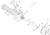
図1を参照すると、寛骨臼プロテーゼコンポーネント10及び整形外科用手術器具アセンブリ12(以下、アセンブリ12と称する)が示されている。アセンブリ12が、股関節形成術において、患者の骨に寛骨臼プロテーゼコンポーネント10のトライアルを合わせ、該コンポーネント10を設置するために使用することができる。しかしながら、アセンブリ12については股関節形成術の手術要領に関して下記に述べるが、アセンブリ12に関連する特定の概念が全身の他の多くの関節の置換要領に利用可能である点は認識されるはずである。言い換えると、アセンブリ12の要素の1以上を例えば膝、脊椎、肩、又は他の置換要領に使用される手術器具に組み込むことができる。 Referring to FIG. 1, an
寛骨臼プロテーゼコンポーネント10が、患者の外科的に準備された寛骨臼16(図5を参照)内に移植されるように構成された寛骨臼シェルコンポーネント14を有している。寛骨臼シェルコンポーネント14が、半球状又は部分的に球状の凸形状を有する外表面20を有している。寛骨臼シェルコンポーネント14は、部分的に球状の凹形状を有する内表面22を更に有している。内表面22が、寛骨臼シェルコンポーネント14内に金属製又はポリマー製のインサートを受容するようなサイズに構成された空洞24を画定している。 The
寛骨臼シェルコンポーネント14が、外表面20に画定された開口部26を有しており、開口部26から内表面22に画定された開口部30へと内壁28が内側に延びている。内壁28が寛骨臼シェルコンポーネント14を貫通する通路32を画定している。図1に示されるように、内壁28上には複数のめねじ34が画定されている。 The
整形外科用手術器具アセンブリ12が、外科ツール40及び位置インジケータ42を有している。この例示的な実施形態では、外科ツール40が埋伏ツールである。他の実施形態では、外科ツール40が、位置決めツール又は寛骨臼プロテーゼコンポーネント10に取り付けられるように構成された他の外科装置であってもよい点は認識されるはずである。外科ツール40は、寛骨臼シェルコンポーネント14のねじ34に対応した複数のおねじ46を有するシャフト44を有している。図1に示されるように、おねじ46はシャフト44の端部48に画定されているため、寛骨臼シェルコンポーネント14をシャフト44の端部48に螺着することによって、トライアル合わせ又は移植を行うために寛骨臼シェルコンポーネント14を外科ツール40に連結することができる。 The orthopedic
外科ツール40のシャフト44が、端部48から端部52へと延びて縦軸54を画定する円筒状本体50を有している。外科ツール40が、シャフト44の端部52に連結されたハンドル56を有している。図1に示されるように、ハンドル56がハンドル本体58を有しており、この例示的な実施形態では、シャフト44がハンドル本体58に対して縦軸54を中心として旋回動作することが可能となっている。 The
外科ツール40は、シャフト44が軸54を中心として旋回することを防止するように構成されたロック機構60を更に有している。ロック機構60がハンドル本体58内に配置され、ハンドル本体58に画定された開口部64内に配置されたボタン62を有している。使用者がボタン62を操作してロック機構60を解除することにより、シャフト44が軸54を中心として旋回することが可能となる。他の実施形態では、ロック機構60は、スイッチ、タブ、又はハンドル本体58に対してシャフト44をロック解除又はロックするための使用者によって操作される他の装置を有しうる点は認識されるはずである。他の実施形態では、シャフト44及びハンドル56は、シャフト44がハンドル56に対して旋回又は回転しないように一体型コンポーネントとして形成可能である点は認識されるはずである。 The
図1に示されるように、外科ツール40のハンドル56が、ハンドル本体58に取り付けられたグリップ66を更に有している。グリップ66は、外科医又は他の使用者の手を受けるようなサイズに構成された刻み付き外表面68を有している。他の実施形態では、外表面はほぼ平滑であってもよく、あるいは使用者の手を支持するための多数のリブを有してもよい点は認識されるはずである。 As shown in FIG. 1, the
外科ツール40のハンドル本体58が、位置インジケータ42を受容するように構成されたプラットフォーム70を更に有している。プラットフォーム70が上面72を有し、開口部74が上面72に画定されている。図1に示されるように、開口部74がほぼ真っ直ぐな縁76と湾曲しているか又は丸みを帯びた縁78とによって画定されている。ほぼ平面状の内壁80が縁76から内側に傾斜している。内壁80が、丸味を帯びた縁78から内側に傾斜する湾曲した内壁82とともにハンドル本体58に穴84を画定している。下記により詳細に述べるように、穴84が位置インジケータ42のロッド86を受容するようなサイズ及び形状に構成されている。 The
次に図2を参照すると、アセンブリ12の位置インジケータ42が、ハウジング90及びハウジング90の下端92に取り付けられたロッド86に延びる縦軸88を有している。ロッド86が、ハウジング90の下端92から延びるカンチレバー支持アーム94を有している。支持アーム94が、ハンドル本体58の湾曲した内壁82と整合する形状を有する湾曲した外表面96を有している。支持アーム94が、外表面96の反対側に配置されたほぼ平面状の表面98を有している。 Referring now to FIG. 2, the
位置インジケータ42のロッド86が、ハウジング90の下端92から延びるカンチレバーバネアーム100を更に有している。バネアーム100が、支持アーム94の表面98と対向するほぼ平面状の表面102を有している。バネアーム100が、表面102の反対側に配置された別のほぼ平面状の表面104を更に有している。バネアーム100の表面104が、ハンドル本体58のほぼ平面状の内壁80と整合する形状に構成されている。 The
この例示的な実施形態では、ロッド86のバネアーム100が、非圧縮位置と圧縮位置との間で支持アーム94に対して撓曲して動くように構成されている。図2に示されるように、バネアーム100の先端部106と支持アーム94の先端部108とによってロッド86の非圧縮状態の厚さ110が規定される。非圧縮状態の厚さ110が、ハンドル本体58の開口部74のサイズよりも大きい。 In this exemplary embodiment, the
位置インジケータ42を外科ツール40に取り付けるには、ハンドル本体58に画定された穴84内にロッド86を進める。ロッド86のアーム94、100を、穴84を画定するハンドル本体58の内壁82、80とそれぞれ接触するように進める。バネアーム100が内壁80と係合すると、非圧縮位置から圧縮位置へと支持アーム94に対して動き、これによりロッド86がハンドル本体58の内壁82、80に沿って進むことが可能となる。図4に示されるように位置インジケータ42が外科ツール40に取り付けられると、バネアーム100は位置インジケータ42がハンドル本体58から不用意に外れることを防止する付勢要素として機能する。 To attach the
ロッド86のアーム94、100が穴84の形状と整合する鍵として形成されていることにより、位置インジケータ42は外科ツール40に対して1つの所定の向きに配置される。他の実施形態では、位置インジケータ42のロッドを、ハンドル本体58の穴の構造と整合するように同様に鍵として形成された1本のシャフトとしてもよい点は認識されるはずである。更に、他の実施形態では、穴を円筒状とし、この穴に受容されるようなサイズに構成された1本の円筒状シャフトをロッドが有するようにしてもよい。他の実施形態では、位置インジケータが複数の所定の位置の間でその軸88を中心として回転することができるように位置インジケータ及び外科ツールが構成されてもよい。 The
他の実施形態では、アセンブリ12は、例えばラッチ、ピン、ネジ形成された締結要素、及び、位置インジケータをハンドル本体に取り付ける他の保持装置などの他のロック機構を有してもよい点も認識されるはずである。他の実施形態では、通常の使用時には位置インジケータ42をハンドル本体58から取り外すことができないように位置インジケータ42をハンドル本体58に固定することができる点も認識されるはずである。 It will also be appreciated that in other embodiments, the
次に図3を参照すると、アセンブリ12の位置インジケータ42は、重力式インジケータ112が取り付けられたハウジング90を有している。本明細書において言うところの「重力式インジケータ」とは、重力に基づいて位置を示すセンサーである。この例示的な実施形態では、重力式インジケータ112は気泡インジケータ114である。他の実施形態では、重力式インジケータ112は、例えば液体で満たされた密閉された浅い皿状容器のような傾きセンサーとすることができる。浅い皿状容器内にボールベアリングを配置し、浅い皿状容器の角度又は傾きに基づいて動くように構成する。 Referring now to FIG. 3, the
位置インジケータ42の気泡インジケータ114は、例えばイソプロピルアルコールなどの液体で満たされたチャンバ118を画定する容器116を有している。この例示的な実施形態では、容器116はドーム形状のチャンバ118を画定している。気泡120はチャンバ118内に閉じ込められている。重力、及び、気泡120の気体とチャンバ118内の液体との間の物理的な差によって気泡インジケータ114の機能は制御され、気泡120は容器116の高い方の側となる容器116の側に浮ぶ。 The
気泡インジケータ114の容器116が、ほぼ透明なフェースプレート122を有している。これにより、使用者はフェースプレート122を通して見ることで気泡120の位置を知ることができる。図3に示されるように、気泡インジケータ114が、フェースプレート122の外表面126にエッチングされた複数のマーク124を有している。マーク124のそれぞれが、患者の外科的に準された寛骨臼16内における寛骨臼プロテーゼコンポーネント10の所定の位置を示している。 The
この例示的な実施形態では、気泡インジケータ114のマーク124は、寛骨臼プロテーゼコンポーネント10の複数の所定の位置に対応した複数のグラフィックインジケータ128を含んでいる。マーク124が、グラフィックインジケータ128に関連付けられた複数の数値インジケータ130を更に含んでいる。図3に示されるように、グラフィックインジケータ128が、リング132、134、136を含んでおり、気泡120は下記により詳しく述べるように患者の外科的に準備された寛骨臼16内における寛骨臼プロテーゼコンポーネント10の位置に基づいてリング132、134、136のそれぞれと位置が合うように構成されている。マーク124が、グラフィックインジケータ128及び数値インジケータ130を患者の身体の特定の側(すなわち右又は左)と関連付けるサイドインジケータ138を更に含んでいる。 In the exemplary embodiment, mark 124 of
位置インジケータ42のハウジング90が、例えばアルミニウム又はチタンなどの移植グレードの金属材料で形成される。容器116はハウジング90内に封入されているため、位置インジケータ42をオートクレーブして何度も使用することができる。他の実施形態では、ハウジング90は、例えばプラスチックなどのポリマー材料から成形してもよい。位置インジケータ42は、再使用可能又は使い捨て式の手術器具であってよい点は認識されるはずである。 The
使用時には、外科医又は他の使用者が、アセンブリ12をトライアルに利用し、かつ寛骨臼プロテーゼコンポーネント10を移植することができる。これを行うには、図4に示されるように外科ツール40を位置インジケータ42及び寛骨臼プロテーゼコンポーネント10と組み立てる。図5及び6に示されるように、外科ツール40を使用して寛骨臼プロテーゼコンポーネント10を患者の寛骨臼16内に初期の所定の位置かつ所定の外転角度で配置することができる。図8及び10に示されるように、外科ツール40を使用して寛骨臼プロテーゼコンポーネント10を患者の寛骨臼16内に別の所定の位置かつ別の所定の外転角度で配置することができる。 In use, a surgeon or other user can use the
図4に示されるように、位置インジケータ42をツール40に取り付けることができる。上記に述べたように、位置インジケータ42のロッド86をハンドル本体58に画定された穴84内に進める。ロッド86のアーム94、100を、穴84を画定するハンドル本体58の内壁82、80とそれぞれ接触するように進める。バネアーム100は内壁80と係合すると非圧縮位置から圧縮位置へと支持アーム94に対して動き、これによりロッド86がハンドル本体58の内壁82、80に沿って進むことが可能となり、位置インジケータ42がツール40と組み立てられる。 As shown in FIG. 4, a
寛骨臼プロテーゼコンポーネント10もツール40に取り付けることができる。これを行うには、寛骨臼シェルコンポーネント14に画定された通路32をツール40のシャフト44と整列させる。寛骨臼シェルコンポーネント14をシャフト44の端部48と接触するように進めることにより、寛骨臼シェルコンポーネント14のネジ山34がシャフト44のネジ山46と嵌合する。次にツール40及び寛骨臼シェルコンポーネント14の一方を他方のコンポーネントに対して回転させて寛骨臼シェルコンポーネント14をシャフト44の端部48に螺着することにより、寛骨臼シェルコンポーネント14を外科ツール40に固定する。 An
寛骨臼シェルコンポーネント14が外科ツール40に固定された状態で、図5に示されるように寛骨臼シェルコンポーネント14を患者の外科的に準備された寛骨臼16内に進めることができる。これを行うには、患者を右又は左側臥位に寝かせることによって、患者の外科的に準備された寛骨臼16が上を向くようにするとよい。図6に示されるように、左側臥位では、患者の身体140は、仮想軸144によって示される地面に対して平行に延びる横軸142を規定する。患者の身体140は更に冠状面146を規定し、冠状軸148が、冠状面146及び横軸142に対して直角に延びる。 With the
使用者はツール40を使用して寛骨臼シェルコンポーネント14を、患者の外科的に準備された寛骨臼16内の初期の所定の位置へと回転させることができる。図6に示されるように、外科ツール40が患者の身体140によって規定される冠状面146内に置かれると、外科ツール40の縦軸54及び位置インジケータ42の縦軸88は冠状面146内に位置する。使用者は、外科ツール40を冠状面146内に維持したままで外科ツール40を冠状軸148を中心として回転させて寛骨臼シェルコンポーネント14を動かすことができる。外科ツール40が軸148を中心として旋回されるのにしたがって、気泡120が位置インジケータ42の容器116内で動く。 The user can use the
図7に示されるように、気泡120が容器116のフェースプレート122上に画定されたリング132と位置合わせされる際に、寛骨臼シェルコンポーネント14が初期の所定の位置に配置される。位置インジケータ42の縦軸88は、フェースプレート122の中心156を通って外側に延びており、リング132は中心156に位置合わせされている。初期の所定の位置では、図7に示されるように冠状面146は縦軸88と整列しており、リング132を二等分している。 As shown in FIG. 7, the
図6に示されるように、リング132に対応する所定の位置では、外科ツール40の縦軸54と、横断方向軸142との間に角度αが規定される。この例示的な実施形態では、角度αは冠状軸148を中心とした所定の回転量に等しく、所定の外転角度である。位置インジケータ42のフェースプレート122は、図7に示されるように角度αの大きさを使用者に対して示す数値インジケータ150を有している。この例示的な実施形態では、角度αは45°の大きさを有している。 As shown in FIG. 6, at a predetermined position corresponding to the
図8に示されるように、使用者はツール40を使用して寛骨臼シェルコンポーネント14を患者の外科的に準備された寛骨臼16内において初期の所定の位置から別の所定の位置へと回転させることができる。これを行うには、使用者は外科ツール40を横軸142及び/又は冠状軸148を中心として回転させることによって寛骨臼シェルコンポーネント14を動かすことができる。この例示的な実施形態では、使用者が横軸142を中心として外科ツール40を回転させることにより、外科ツール40は冠状面146の外に出る。図8に示されるように、外科ツール40は冠状面146に対して前方に回転されている。使用者はまた、冠状軸148に対して外科ツール40を回転させる。 As shown in FIG. 8, the user uses the
外科ツール40が軸142、148を中心として旋回されるのにしたがって、気泡120が位置インジケータ42の容器116内で動く。図9に示されるように、気泡120が容器116のフェースプレート122上に形成されたリング134と位置合わせされる際に、寛骨臼シェルコンポーネント14は第2の所定の位置に位置する。 As
図8に示されるように、リング134に対応する所定の位置では、外科ツール40の縦軸54と、冠状面146との間に角度βが規定される。この例示的な実施形態では、角度βは横軸142を中心とした所定の回転量に等しく、所定の前捻角度である。図10に示されるように、リング134に対応する所定の位置では、外科ツール40の縦軸54と、横軸142との間に角度φが規定される。この例示的な実施形態では、角度φは冠状軸を中心とした所定の回転量に等しく、所定の外転角度である。位置インジケータ42のフェースプレート122は、図9に示されるように角度β、φの大きさを使用者に対して示す数値インジケータ152、154を有している。この例示的な実施形態では、角度βは15°の大きさを有し、角度φは40°の大きさを有している。 As shown in FIG. 8, at a predetermined position corresponding to the
角度α、β、φの大きさは、特定の患者の解剖学的構造にしたがって変わりうる点は認識されるはずである。例えば、角度α、φの大きさは35°〜50°の間であってよく、又は例えば角度βの大きさは15〜30°であってよい。異なる所定の位置を示すマークを有する異なる位置インジケータを、設置プロセスにおいて使用することができる点は認識されるはずである。他の実施形態では、位置インジケータはカスタマイズされた患者別の位置インジケータとすることができる。本明細書において言うところの「カスタマイズされた患者別の」なる用語は、1人の患者で使用されるために作製された構造のことを指す。例えば、位置インジケータは、特定の患者に固有の寛骨臼プロテーゼコンポーネントのカスタマイズされた所定の位置に対応したマークを有しうる。他の実施形態では、位置インジケータのマークは外科医の好みに基づいたものとすることもできる。 It should be appreciated that the magnitude of the angles α, β, φ can vary according to the particular patient anatomy. For example, the magnitudes of the angles α, φ may be between 35 ° and 50 °, or for example, the magnitude of the angle β may be 15-30 °. It should be appreciated that different position indicators with marks indicating different predetermined positions can be used in the installation process. In other embodiments, the position indicator may be a customized patient-specific position indicator. As used herein, the term “customized patient-specific” refers to a structure made for use with a single patient. For example, the position indicator may have a mark corresponding to a customized predetermined position of the acetabular prosthesis component that is specific to a particular patient. In other embodiments, the position indicator marks may be based on surgeon preference.
更に、アセンブリ12は上記に概略を述べた手術において寛骨臼プロテーゼコンポーネント10とともに使用されるが、アセンブリ12は寛骨臼プロテーゼトライアルコンポーネントとともに使用することもできる。トライアルコンポーネントに取り付けられる場合、使用者はアセンブリ12を使用して、移植しようとする寛骨臼プロテーゼコンポーネントの種類、形態、及び設置位置を決定することができる。トライアル合わせプロセスにおいて、異なる所定の位置を示すマークを有する異なる位置インジケータを使用して寛骨臼プロテーゼコンポーネントの設置位置を決定することができる点は認識されるはずである。 Further, although the
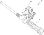
次に図11を参照すると、位置インジケータの別の実施形態(以下、位置インジケータ242)が示されている。図11に示される実施形態の要素の一部のものは、図1〜図10の実施形態を参照して上記に述べたものと実質的に同様である。そのような要素は、図11では、図1〜図10で使用したものと同じ参照符合を用いて示している。位置インジケータ42と同様、位置インジケータ242が、外科ツール40に取り付けられるように構成されている。 Referring now to FIG. 11, another embodiment of a position indicator (hereinafter, position indicator 242) is shown. Some of the elements of the embodiment shown in FIG. 11 are substantially similar to those described above with reference to the embodiment of FIGS. Such elements are shown in FIG. 11 with the same reference numerals as used in FIGS. Similar to the
位置インジケータ242が、ハウジング90及びハンドル本体58の穴84内に受容されるようなサイズに構成されたロッド(図に示されていない)を有している。位置インジケータ242は、例えばイソプロピルアルコールなどの液体で満たされたドーム形状のチャンバ118を画定する容器246を有する気泡インジケータ244を有している。位置インジケータ42の容器116と同様、気泡120がチャンバ118内部に閉じ込められている。重力、及び、気泡120の気体とチャンバ118内の液体との間の物理的な差によって気泡インジケータ244の機能は制御され、気泡120は容器246の高い方の側となる容器246の側に浮ぶ。 The
気泡インジケータ244の容器246は、ほぼ透明なフェースプレート248を有している。これにより、使用者はフェースプレート248を通して見ることで気泡120の位置を知ることができる。図11に示されるように、気泡インジケータ244は、フェースプレート248の外表面252にエッチングされた複数のマーク250を有している。マーク250のそれぞれは、外科的に準備処置が施された患者の寛骨臼16内における寛骨臼プロテーゼコンポーネント10の所定の位置に対応している。 The
この例示的な実施形態では、気泡インジケータ244のマーク250は、寛骨臼プロテーゼコンポーネント10の複数の所定の位置に対応した複数のグラフィックインジケータ254を含んでいる。図11に示されるように、グラフィカルインジケータ254が、図1〜10を参照して上記に述べた角度α、β、φに対応したリング132、134、136を含んでいる。気泡インジケータ244のグラフィカルインジケータ254が、寛骨臼プロテーゼコンポーネント10の更なる所定の位置に対応した複数の更なる円弧256を更に含んでいる。この例示的な実施形態では、マーク254が、グラフィカルインジケータ254と関連付けられた、異なる所定の位置における角度α、β、φの大きさを使用者に対して示す複数の数値インジケータ258を更に含んでいる。 In the exemplary embodiment, mark 250 of
使用時には、外科医が位置インジケータ242を使用して、マーク250によって示される複数の所定の位置から寛骨臼プロテーゼコンポーネント10の適正な位置を決定することができる。例えば、寛骨臼プロテーゼトライアルコンポーネントとともに使用される場合、使用者が位置インジケータ242を使用して、複数の所定の位置の間で寛骨臼プロテーゼコンポーネント10を動かすことにより寛骨臼プロテーゼコンポーネント10の種類、形態、及び設置位置を決定することができる。 In use, the surgeon can use the
次に図12を参照すると、位置インジケータの別の実施形態(以下、インジケータ342)が外科ツール40に取り付けられた状態が示されている。図12に示される実施形態の要素の一部のものは、図1〜図10の実施形態を参照して上記に述べたものと実質的に同様である。そのような要素は、図12では、図1〜図10で使用したものと同じ参照符合を用いて示している。位置インジケータ42と同様、位置インジケータ242が、外科ツール40に取り付けられるように構成されている。 Referring now to FIG. 12, another embodiment of a position indicator (hereinafter indicator 342) is shown attached to the
位置インジケータ342が、ハウジング344及びハンドル本体58の穴84内に受容されるようなサイズに構成されたロッド86を有している。ハウジング344は、外科ツール40の縦軸54と平行に延びるアーム346、及びアーム346に直角に延びる基部348を有している。図12に示されるように、位置インジケータ342が、アーム346に固定された気泡インジケータ350と、基部348に固定された別の気泡インジケータ352とを含んでいる。 The
気泡インジケータ350が、外科ツール40の軸54と平行に延びる長円形の容器354を有している。容器354が、例えばイソプロピルアルコールのような液体で満たされたチャンバ356を画定しており、気泡358がチャンバ356内に閉じ込められている。気泡インジケータ352が、容器354に直角に延びる長円形の容器360を有している。容器360は、液体で満たされたチャンバ362を画定しており、気泡364がチャンバ362内に閉じ込められている。重力、及び、それぞれ気泡358、364の気体とチャンバ356、362内の液体との間の物理的な差によって気泡インジケータ350、352の機能は制御され、気泡358、364は容器354、360の高い方の側に浮ぶ。 The
気泡インジケータ350、352のそれぞれが、フェースプレート370、372をそれぞれ有している。フェースプレート370、372がほぼ透明である。これにより、使用者がフェースプレート370、372を通して見ることで気泡350、352のそれぞれの位置を知ることができる。フェースプレート370は、患者の外科的に準備された寛骨臼16内における寛骨臼プロテーゼコンポーネント10の複数の所定の位置を示す複数のマーク374を有している。この例示的な実施形態では、マーク374が冠状軸148を中心とした所定の回転量及び所定の外転角度に対応している。 Each of the
気泡インジケータ352のフェースプレート372は、患者の外科的に準備された寛骨臼16内における寛骨臼プロテーゼコンポーネント10の複数の所定の位置を示す複数のマーキング376を有している。この例示的な実施形態では、マーク376は横軸142を中心とした所定の回転量及び所定の前捻角度に対応している。 The
この例示的な実施形態では、気泡インジケータ350、352のマーク374、376は、患者の外科的に準された寛骨臼16内における寛骨臼プロテーゼコンポーネント10の複数の所定の位置に対応した複数のグラフィックインジケータ380、382を有している。他の実施形態では、マーク374、376が、図1〜10に関して上記に述べたものと同様の数値インジケータ又はサイドインジケータを有してもよい点は認識されるはずである。 In this exemplary embodiment, the
以上、図面及び上記の説明文において本開示内容を詳細に図示、説明したが、こうした図示、説明はその性質上、例示的なものとみなすべきであって、限定的なものとみなすべきではなく、あくまで例示的実施形態を示し、説明したものにすぎないのであって、本開示の趣旨の範囲に含まれる変更及び改変はすべて保護されることが望ましい点は理解されるであろう。 As described above, the present disclosure has been illustrated and described in detail in the drawings and the above description. However, such illustration and description should be regarded as illustrative in nature and not as restrictive. It will be understood that the exemplary embodiments have been shown and described only and that it is desirable to protect all changes and modifications that fall within the scope of the present disclosure.
本開示は、本明細書において述べた方法、装置、及びシステムの様々な特徴に基づく多くの利点を有するものである。本開示の方法、装置、及びシステムの代替的実施形態は、ここで述べた特徴のすべてを含むわけではないが、こうした特徴の利点の少なくとも一部から利するものである点に留意されたい。当業者であれば、本発明の1以上の特徴を取り入れた、特許請求の範囲において定義される本開示の趣旨及び範囲に包含される方法、装置、及びシステムを独自に容易に実施することが可能である。 The present disclosure has many advantages based on various features of the methods, apparatus, and systems described herein. It should be noted that alternative embodiments of the disclosed methods, apparatus, and systems do not include all of the features described herein, but benefit from at least some of the advantages of these features. One of ordinary skill in the art can readily implement the methods, apparatus, and systems uniquely, which incorporate one or more features of the present invention and fall within the spirit and scope of the present disclosure as defined in the claims. Is possible.
〔実施の態様〕
(1) 患者の外科的に準備された寛骨臼内に寛骨臼プロテーゼコンポーネントを配置するための整形外科用手術器具であって、
前記寛骨臼プロテーゼコンポーネントと連結されるように構成された第1の端部を有するシャフトと、
前記第1の端部の反対側の第2の端部において前記シャフトに取り付けられたハンドルと、
前記第1の端部と前記第2の端部との間において前記シャフトに取り付けられ、フェースと該フェース上に画定された複数のマークとを有する気泡インジケータであって、該複数のマークが、
(i)第1の外転角度を示す第1のマークと、
(ii)第2の外転角度及び前記寛骨臼プロテーゼコンポーネントの前捻角度を示す第2のマークと、を含むものである、気泡インジケータと、を備えた整形外科用手術器具。
(2) 前記第2の外転角度が前記第1の外転角度よりも小さい、実施態様1に記載の整形外科用手術器具。
(3) 前記第1の外転角度が約45°である、実施態様2に記載の整形外科用手術器具。
(4) 前記第2の外転角度が約40°である、実施態様3に記載の整形外科用手術器具。
(5) 前記前捻角度が前記患者を通って延びる横軸を中心として約15°の回転に等しい、実施態様4に記載の整形外科用手術器具。Embodiment
(1) an orthopedic surgical instrument for placing an acetabular prosthetic component within a patient's surgically prepared acetabulum, comprising:
A shaft having a first end configured to be coupled with the acetabular prosthesis component;
A handle attached to the shaft at a second end opposite the first end;
A bubble indicator attached to the shaft between the first end and the second end and having a face and a plurality of marks defined on the face, the plurality of marks comprising:
(I) a first mark indicating a first abduction angle;
(Ii) an orthopedic surgical instrument comprising a bubble indicator, comprising: a second abduction angle and a second mark indicating the anteversion angle of the acetabular prosthesis component.
(2) The surgical instrument for orthopedic surgery according to embodiment 1, wherein the second abduction angle is smaller than the first abduction angle.
(3) The surgical instrument for orthopedic surgery according to
(4) The surgical instrument for orthopedic surgery according to embodiment 3, wherein the second abduction angle is about 40 °.
5. The orthopedic surgical instrument of embodiment 4, wherein the anteversion angle is equal to about 15 ° rotation about a transverse axis extending through the patient.
(6) 前記気泡インジケータが前記シャフトから脱着可能である、実施態様1に記載の整形外科用手術器具。
(7) 前記第1のマーク及び前記第2のマークが、カスタマイズされた患者別のマークである、実施態様1に記載の整形外科用手術器具。
(8) 前記フェースが円形で中心点を有しており、かつ前記第1のマークが前記フェースの前記中心点にほぼ位置している、実施態様1に記載の整形外科用手術器具。
(9) 前記第2のマークが、前記フェースの前記中心点からずれている、実施態様8に記載の整形外科用手術器具。
(10) 前記第1のマークが、前記第1の外転角度のグラフィックインジケータ及び数値インジケータを含む、実施態様1に記載の整形外科用手術器具。(6) The surgical instrument for orthopedic surgery according to embodiment 1, wherein the bubble indicator is detachable from the shaft.
(7) The surgical instrument for orthopedic surgery according to embodiment 1, wherein the first mark and the second mark are customized patient-specific marks.
(8) The surgical instrument for orthopedic surgery according to embodiment 1, wherein the face is circular and has a center point, and the first mark is located substantially at the center point of the face.
(9) The surgical instrument for orthopedic surgery according to embodiment 8, wherein the second mark is offset from the center point of the face.
The orthopedic surgical instrument according to claim 1, wherein the first mark includes a graphic indicator and a numerical indicator of the first abduction angle.
(11) 患者の外科的に準備された寛骨臼内に寛骨臼プロテーゼコンポーネントを配置するための整形外科用手術器具であって、
前記寛骨臼プロテーゼコンポーネントと連結されるように構成された外科ツールと、
前記外科ツールと着脱可能に連結された重力式位置インジケータであって、
(i)前記患者の外科的に準備された寛骨臼内における前記寛骨臼プロテーゼコンポーネントの第1の位置を示す第1のマークと、
(ii)前記患者の外科的に準備された寛骨臼内における前記寛骨臼プロテーゼコンポーネントの第2の位置を示す第2のマークと、を有する、重力式位置インジケータと、を備える整形外科用手術器具。
(12) 前記第1のマークが第1の外転角度を示し、かつ前記第2のマークが第2の外転角度を示し、前記第2の外転角度が前記第1の外転角度と異なる、実施態様11に記載の整形外科用手術器具。
(13) 前記外科ツールに穴が画定されており、
前記位置インジケータが前記外科ツールの前記穴に合うように成形されたロッドを有することにより、前記位置インジケータが1つの所定の向きで前記外科ツールと連結される、実施態様11に記載の整形外科用手術器具。
(14) 前記外科ツールの一端に複数のおねじが形成され、該複数のおねじが前記寛骨臼プロテーゼコンポーネントの複数のめねじと対応していることにより、前記外科ツールを前記寛骨臼プロテーゼコンポーネントに螺着することが可能である、実施態様11に記載の整形外科用手術器具。
(15) 患者の外科的に準備された寛骨臼内に寛骨臼プロテーゼコンポーネントを配置する方法であって、
気泡インジケータの気泡が、前記寛骨臼プロテーゼコンポーネントの第1の位置を示す第1のマークとほぼ位置が合うまで前記患者の外科的に準備された寛骨臼内において前記寛骨臼プロテーゼコンポーネントを回転させることと、
前記気泡が、前記寛骨臼プロテーゼコンポーネントの第2の位置を示す第2のマークとほぼ位置が合うまで前記寛骨臼プロテーゼコンポーネントを前方に回転させることと、を含む方法。(11) An orthopedic surgical instrument for placing an acetabular prosthetic component within a patient's surgically prepared acetabulum, comprising:
A surgical tool configured to be coupled with the acetabular prosthesis component;
A gravitational position indicator detachably coupled to the surgical tool,
(I) a first mark indicating a first position of the acetabular prosthesis component within the patient's surgically prepared acetabulum;
(Ii) an orthopedic surgical instrument comprising: a gravitational position indicator having a second mark indicating a second position of the acetabular prosthesis component in a surgically prepared acetabulum of the patient; Surgical instruments.
(12) The first mark indicates a first abduction angle, the second mark indicates a second abduction angle, and the second abduction angle is equal to the first abduction angle.
(13) a hole is defined in the surgical tool;
12. The orthopedic surgery of embodiment 11, wherein the position indicator is coupled to the surgical tool in one predetermined orientation by having a rod shaped to fit the hole in the surgical tool. Surgical instruments.
(14) A plurality of male screws are formed at one end of the surgical tool, and the plurality of male screws correspond to a plurality of female screws of the acetabular prosthesis component, thereby allowing the surgical tool to move to the acetabulum The orthopedic surgical instrument of claim 11, wherein the orthopedic surgical instrument is threadable to the prosthesis component.
(15) A method of placing an acetabular prosthetic component within a patient's surgically prepared acetabulum comprising:
The acetabular prosthesis component is positioned within the patient's surgically prepared acetabulum until the bubble of the bubble indicator is substantially aligned with a first mark indicating a first position of the acetabular prosthesis component. Rotating,
Rotating the acetabular prosthesis component forward until the bubble is substantially aligned with a second mark indicating a second position of the acetabular prosthesis component.
(16) 前記寛骨臼プロテーゼコンポーネントが前記第1の位置において第1の外転角度にあり、
前記寛骨臼プロテーゼコンポーネントが前記第2の位置において前記第1の外転角度よりも小さい第2の外転角度にある、実施態様15に記載の方法。
(17) 前記第1の外転角度が約45°である、実施態様16に記載の方法。
(18) 前記第2の外転角度が約40°である、実施態様16に記載の方法。
(19) 前記寛骨臼プロテーゼコンポーネントを前方に回転させることが、前記患者を通じて延びる横軸を中心として前記寛骨臼プロテーゼコンポーネントを約15°回転させることを含む、実施態様18に記載の方法。
(20) 前記気泡が、前記寛骨臼プロテーゼコンポーネントの第3の位置に対応した第3のマークとほぼ位置が合うまで、前記患者の外科的に準備された寛骨臼内において前記寛骨臼プロテーゼコンポーネントを回転させることを更に含む、実施態様15に記載の方法。(16) the acetabular prosthesis component is at a first abduction angle in the first position;
16. The method of
17. The method of
18. The method of
19. The method of embodiment 18, wherein rotating the acetabular prosthetic component forward comprises rotating the acetabular prosthetic component about 15 degrees about a transverse axis extending through the patient.
(20) The acetabulum in the surgically prepared acetabulum of the patient until the air bubble is substantially aligned with a third mark corresponding to a third position of the acetabular prosthesis component.
(21) 複数の気泡インジケータから前記気泡インジケータを選択することと、
前記気泡インジケータを外科ツールに取り付けることと、
前記寛骨臼プロテーゼコンポーネントを前記外科ツールに螺着することと、を更に含む、実施態様15に記載の方法。
(22) 前記気泡インジケータの前記気泡が前記第1のマークとほぼ位置が合うまで前記患者の外科的に準備された寛骨臼内において前記寛骨臼プロテーゼコンポーネントを回転させることが、前記第1のマークのグラフィックインジケータを前記気泡インジケータの前記気泡と位置合わせすることを含む、実施態様15に記載の方法。
(23) 前記患者の身体によって画定される冠状面内に前記第1のマークが前記冠状面と位置が合うように前記気泡インジケータを配置することを更に含み、
前記患者の外科的に準備された寛骨臼内において前記寛骨臼プロテーゼコンポーネントを回転させることが、前記第1のマークと前記冠状面との間の位置合わせを維持すること、を含む、実施態様15に記載の方法。(21) selecting the bubble indicator from a plurality of bubble indicators;
Attaching the bubble indicator to a surgical tool;
16. The method of
(22) rotating the acetabular prosthetic component in the patient's surgically prepared acetabulum until the bubble of the bubble indicator is substantially aligned with the first mark; 16. The method of
(23) further comprising positioning the bubble indicator such that the first mark is aligned with the coronal plane within a coronal plane defined by the patient's body;
Rotating the acetabular prosthetic component within the patient's surgically prepared acetabulum comprises maintaining alignment between the first mark and the coronal plane The method according to
Claims (14)
Translated fromJapanese前記寛骨臼プロテーゼコンポーネントと連結されるように構成された第1の端部を有するシャフトと、
前記第1の端部の反対側の第2の端部において前記シャフトに取り付けられたハンドルと、
前記第1の端部と前記第2の端部との間において前記シャフトに取り付けられ、フェースと該フェース上に画定された複数のマークとを有する気泡インジケータであって、該複数のマークが、
(i)第1の外転角度を示す第1のマークと、
(ii)第2の外転角度及び前記寛骨臼プロテーゼコンポーネントの前捻角度を示す第2のマークと、を含むものである、気泡インジケータと、を備えた整形外科用手術器具。An orthopedic surgical instrument for placing an acetabular prosthetic component within a patient's surgically prepared acetabulum, comprising:
A shaft having a first end configured to be coupled with the acetabular prosthesis component;
A handle attached to the shaft at a second end opposite the first end;
A bubble indicator attached to the shaft between the first end and the second end and having a face and a plurality of marks defined on the face, the plurality of marks comprising:
(I) a first mark indicating a first abduction angle;
(Ii) an orthopedic surgical instrument comprising a bubble indicator, comprising: a second abduction angle and a second mark indicating the anteversion angle of the acetabular prosthesis component.
前記寛骨臼プロテーゼコンポーネントと連結されるように構成された外科ツールと、
前記外科ツールと着脱可能に連結された重力式位置インジケータであって、
(i)前記患者の外科的に準備された寛骨臼内における前記寛骨臼プロテーゼコンポーネントの第1の位置を示す第1のマークと、
(ii)前記患者の外科的に準備された寛骨臼内における前記寛骨臼プロテーゼコンポーネントの第2の位置を示す第2のマークと、を有する、重力式位置インジケータと、を備える整形外科用手術器具。An orthopedic surgical instrument for placing an acetabular prosthetic component within a patient's surgically prepared acetabulum, comprising:
A surgical tool configured to be coupled with the acetabular prosthesis component;
A gravitational position indicator detachably coupled to the surgical tool,
(I) a first mark indicating a first position of the acetabular prosthesis component within the patient's surgically prepared acetabulum;
(Ii) an orthopedic surgical instrument comprising: a gravitational position indicator having a second mark indicating a second position of the acetabular prosthesis component in a surgically prepared acetabulum of the patient; Surgical instruments.
前記位置インジケータが前記外科ツールの前記穴に合うように成形されたロッドを有することにより、前記位置インジケータが1つの所定の向きで前記外科ツールと連結される、請求項11に記載の整形外科用手術器具。A hole is defined in the surgical tool;
The orthopedic surgical instrument of claim 11, wherein the position indicator is coupled to the surgical tool in one predetermined orientation by having a rod shaped to fit the hole of the surgical tool. Surgical instruments.
Applications Claiming Priority (2)
| Application Number | Priority Date | Filing Date | Title |
|---|---|---|---|
| US13/434,154US9358130B2 (en) | 2012-03-29 | 2012-03-29 | Surgical instrument and method of positioning an acetabular prosthetic component |
| US13/434,154 | 2012-03-29 |
Publications (2)
| Publication Number | Publication Date |
|---|---|
| JP2013202416Atrue JP2013202416A (en) | 2013-10-07 |
| JP6151060B2 JP6151060B2 (en) | 2017-06-21 |
Family
ID=47915621
Family Applications (1)
| Application Number | Title | Priority Date | Filing Date |
|---|---|---|---|
| JP2013068417AExpired - Fee RelatedJP6151060B2 (en) | 2012-03-29 | 2013-03-28 | Surgical instrument and method for placing an acetabular prosthesis component |
Country Status (5)
| Country | Link |
|---|---|
| US (3) | US9358130B2 (en) |
| EP (1) | EP2644164A1 (en) |
| JP (1) | JP6151060B2 (en) |
| CN (1) | CN103356288B (en) |
| AU (1) | AU2013202008B2 (en) |
Cited By (1)
| Publication number | Priority date | Publication date | Assignee | Title |
|---|---|---|---|---|
| JP2016036646A (en)* | 2014-08-11 | 2016-03-22 | 京セラメディカル株式会社 | Grip for artificial joint surgical instrument and shell positioner |
Families Citing this family (30)
| Publication number | Priority date | Publication date | Assignee | Title |
|---|---|---|---|---|
| JP3010484B2 (en) | 1996-02-15 | 2000-02-21 | 株式会社島精機製作所 | Inner reduction method using flat knitting machine |
| CN105246433B (en) | 2013-06-11 | 2018-06-05 | 奥尔索夫特公司 | Acetabular cup prosthesis positioning apparatus and method |
| FR3010628B1 (en) | 2013-09-18 | 2015-10-16 | Medicrea International | METHOD FOR REALIZING THE IDEAL CURVATURE OF A ROD OF A VERTEBRAL OSTEOSYNTHESIS EQUIPMENT FOR STRENGTHENING THE VERTEBRAL COLUMN OF A PATIENT |
| FR3012030B1 (en) | 2013-10-18 | 2015-12-25 | Medicrea International | METHOD FOR REALIZING THE IDEAL CURVATURE OF A ROD OF A VERTEBRAL OSTEOSYNTHESIS EQUIPMENT FOR STRENGTHENING THE VERTEBRAL COLUMN OF A PATIENT |
| US10085838B2 (en) | 2015-01-15 | 2018-10-02 | Depuy Ireland Unlimited Company | Assembly tool |
| EP3111897B1 (en) | 2015-07-02 | 2018-11-14 | Greatbatch Ltd. | Orthopedic impactor |
| GB201514727D0 (en) | 2015-08-19 | 2015-09-30 | Depuy Ireland | An Assembly Tool |
| US10687852B2 (en) | 2015-09-14 | 2020-06-23 | Symmetry Medical Manufacturing, Inc. | Separable instrument driver handle |
| USD818586S1 (en)* | 2015-10-12 | 2018-05-22 | DePuy Synthes Products, Inc. | Tool handle |
| US10456211B2 (en) | 2015-11-04 | 2019-10-29 | Medicrea International | Methods and apparatus for spinal reconstructive surgery and measuring spinal length and intervertebral spacing, tension and rotation |
| WO2017147469A1 (en)* | 2016-02-24 | 2017-08-31 | Smith & Nephew, Inc. | Orthopedic angular measuring instrument |
| WO2018109556A1 (en) | 2016-12-12 | 2018-06-21 | Medicrea International | Systems and methods for patient-specific spinal implants |
| WO2018139922A1 (en) | 2017-01-24 | 2018-08-02 | Orpidem B.V. | Positioning aid in particular for positioning an acetabular prosthetic component |
| GB201705920D0 (en)* | 2017-04-12 | 2017-05-24 | Depuy Ireland Ultd Co | Apparatus and method for hip surgery |
| EP3612122B1 (en) | 2017-04-21 | 2023-12-20 | Medicrea International | A system for developing one or more patient-specific spinal implants |
| WO2018209042A2 (en) | 2017-05-10 | 2018-11-15 | Mako Surgical Corp. | Robotic spine surgery system and methods |
| US11033341B2 (en) | 2017-05-10 | 2021-06-15 | Mako Surgical Corp. | Robotic spine surgery system and methods |
| US10729558B2 (en)* | 2017-08-18 | 2020-08-04 | Zimmer, Inc. | Methods and systems for patient-specific acetabular implants |
| US10918422B2 (en) | 2017-12-01 | 2021-02-16 | Medicrea International | Method and apparatus for inhibiting proximal junctional failure |
| CN118662240A (en) | 2018-01-26 | 2024-09-20 | 马科外科公司 | End effector, system, and method for impacting a prosthesis guided by a surgical robot |
| CN109009583B (en)* | 2018-09-06 | 2023-11-03 | 绍兴市上虞区中医医院 | Positioning device for placement position of cup |
| RU2697973C1 (en)* | 2018-12-12 | 2019-08-22 | Денис Игоревич Варфоломеев | Method for determining parameters of the locomotor apparatus in hip replacement surgery |
| US11925417B2 (en) | 2019-04-02 | 2024-03-12 | Medicrea International | Systems, methods, and devices for developing patient-specific spinal implants, treatments, operations, and/or procedures |
| US11877801B2 (en) | 2019-04-02 | 2024-01-23 | Medicrea International | Systems, methods, and devices for developing patient-specific spinal implants, treatments, operations, and/or procedures |
| US11944385B2 (en) | 2019-04-02 | 2024-04-02 | Medicrea International | Systems and methods for medical image analysis |
| US11207197B2 (en) | 2019-08-01 | 2021-12-28 | DePuy Synthes Products, Inc. | Orthopaedic surgical instrument for total hip arthroplasty and associated orthopaedic surgical method of use |
| US11583417B2 (en)* | 2019-12-04 | 2023-02-21 | Depuy Ireland Unlimited Company | Removable inclination guide for an implant insertion tool and associated surgical method |
| US11769251B2 (en) | 2019-12-26 | 2023-09-26 | Medicrea International | Systems and methods for medical image analysis |
| CN111281623B (en)* | 2020-03-30 | 2024-07-26 | 北京市春立正达医疗器械股份有限公司 | Acetabulum outer cup mounting locator |
| US12318144B2 (en) | 2021-06-23 | 2025-06-03 | Medicrea International SA | Systems and methods for planning a patient-specific spinal correction |
Citations (3)
| Publication number | Priority date | Publication date | Assignee | Title |
|---|---|---|---|---|
| JP2007510475A (en)* | 2003-11-12 | 2007-04-26 | インターナショナル パテント オーナーズ (ケイマン) リミテッド | Surgical gauge |
| US20100087823A1 (en)* | 2008-10-02 | 2010-04-08 | Kondrashov Dimitriy G | Pedicle preparation device to assist implantation of pedicle screws |
| US20100249657A1 (en)* | 2009-03-24 | 2010-09-30 | Biomet Manufacturing Corp. | Method and Apparatus for Aligning and Securing an Implant Relative to a Patient |
Family Cites Families (50)
| Publication number | Priority date | Publication date | Assignee | Title |
|---|---|---|---|---|
| US534434A (en)* | 1895-02-19 | Lock for telescopic joints | ||
| US1942640A (en) | 1933-03-09 | 1934-01-09 | Frank W Fromme | Wrench |
| US2379796A (en) | 1942-10-01 | 1945-07-03 | Chester H Shively | Brake operating mechanism |
| US4716894A (en) | 1986-08-27 | 1988-01-05 | Zimmer, Inc. | Acetabular cup inserting instrument |
| USD331461S (en) | 1990-11-21 | 1992-12-01 | Zimmer, Inc. | Acetabular cup prosthesis positioning tool |
| US5061270A (en) | 1991-03-18 | 1991-10-29 | Aboczky Robert I | System for orienting, inserting and impacting an acetabular cup prosthesis |
| US5284483A (en) | 1992-09-16 | 1994-02-08 | Zimmer, Inc. | Acetabular cup inserting instrument |
| US5320625A (en) | 1993-01-21 | 1994-06-14 | Bertin Kim C | Apparatus and method for implanting a prosthetic acetabular cup and then testing the stability of the implant |
| US5250051A (en) | 1993-02-08 | 1993-10-05 | Zimmer, Inc. | Acetabular cup positioner with slaphammer mechanism for the removal of the sighting guide |
| US5540697A (en) | 1993-02-12 | 1996-07-30 | U.S. Medical Products, Inc. | Prosthetic socket installation apparatus and method |
| US5584837A (en) | 1993-08-13 | 1996-12-17 | Petersen; Thomas D. | Acetabular cup inserter for orthopedic |
| US5457857A (en) | 1994-01-31 | 1995-10-17 | Lam; Ching-Keung | Pivoted clamp |
| US5364403A (en) | 1993-09-20 | 1994-11-15 | Zimmer, Inc. | Acetabular cup positioner |
| US5658294A (en) | 1993-12-02 | 1997-08-19 | Sulzer Orthopedics Inc. | Instrument for holding an acetabular cup |
| US5683399A (en) | 1995-12-01 | 1997-11-04 | Stelkast Incorporated | Acetabular cup insertion tool |
| FR2744629B1 (en)* | 1996-02-13 | 1998-05-22 | Advanced Technical Fabrication | HIP PROSTHESIS INSTRUMENTATION |
| US5836081A (en)* | 1996-05-29 | 1998-11-17 | Charles F. Schroeder | Light beam leveling means and method |
| JP4265024B2 (en) | 1998-06-22 | 2009-05-20 | トヨタ紡織株式会社 | Reclining device |
| AUPQ363999A0 (en) | 1999-10-25 | 1999-11-18 | Sher, Doron | Device for measuring leg length |
| US6395005B1 (en) | 2000-04-14 | 2002-05-28 | Howmedica Osteonics Corp. | Acetabular alignment apparatus and method |
| DE10200690B4 (en) | 2002-01-10 | 2005-03-03 | Intraplant Ag | Aid for implantation of a hip joint endoprosthesis |
| DE10202582C1 (en) | 2002-01-17 | 2003-09-25 | Aesculap Ag & Co Kg | Surgical targeting gauge for guiding insertion of surgical instrument has 2 relatively adjustable display elements indicating respective display directions |
| US20030199882A1 (en)* | 2002-03-21 | 2003-10-23 | Gorek Josef E. | Gravity dependent pedicle screw tap hole guide and data processing device |
| US6638281B2 (en)* | 2002-03-21 | 2003-10-28 | Spinecore, Inc. | Gravity dependent pedicle screw tap hole guide |
| US7611522B2 (en)* | 2003-06-02 | 2009-11-03 | Nuvasive, Inc. | Gravity dependent pedicle screw tap hole guide and data processing device |
| JP2006509609A (en) | 2002-10-04 | 2006-03-23 | オルトソフト インコーポレイテッド | Computer-aided hip replacement surgery |
| US6743235B2 (en)* | 2002-10-15 | 2004-06-01 | Goli V. Subba Rao | Modular instrument for positioning acetabular prosthetic socket |
| US9610092B2 (en)* | 2011-08-29 | 2017-04-04 | Microsoft Orthopedics Holdings Inc. | Precision hip replacement method |
| US8034057B2 (en)* | 2002-11-07 | 2011-10-11 | Penenberg Brad L | Apparatus for, and method of, preparing for and inserting hip joint prosthesis using computer guidance |
| US9308002B2 (en)* | 2002-11-07 | 2016-04-12 | Crescent H Trust | Precise hip component positioning for hip replacement surgery |
| US7660623B2 (en) | 2003-01-30 | 2010-02-09 | Medtronic Navigation, Inc. | Six degree of freedom alignment display for medical procedures |
| WO2004091419A2 (en)* | 2003-04-08 | 2004-10-28 | Wasielewski Ray C | Use of micro-and miniature position sensing devices for use in tka and tha |
| EP1651151B1 (en)* | 2003-07-24 | 2012-06-06 | San-Tech Surgical Sàrl | Orientation device for surgical implement |
| US20050033315A1 (en)* | 2003-08-01 | 2005-02-10 | Hankins Carol A. | Apparatus and method for guiding a medical device |
| US7037310B2 (en) | 2003-10-21 | 2006-05-02 | Wright Medical Technology Inc | Acetabular impactor |
| WO2005065337A2 (en)* | 2003-12-29 | 2005-07-21 | Hankins Carol A | Apparatus and method for guiding a medical device in multiple planes |
| US8007448B2 (en)* | 2004-10-08 | 2011-08-30 | Stryker Leibinger Gmbh & Co. Kg. | System and method for performing arthroplasty of a joint and tracking a plumb line plane |
| US8608749B2 (en) | 2006-02-27 | 2013-12-17 | Biomet Manufacturing, Llc | Patient-specific acetabular guides and associated instruments |
| KR100794216B1 (en) | 2006-11-13 | 2008-01-11 | 한국과학기술원 | Artificial Hip Acetabular Cup Measuring Device |
| AU2009291743B2 (en) | 2008-09-10 | 2015-02-05 | Orthalign, Inc | Hip surgery systems and methods |
| US8454619B1 (en)* | 2008-12-10 | 2013-06-04 | William C. Head | Prosthetic socket alignment |
| US8469962B1 (en)* | 2008-12-10 | 2013-06-25 | William C. Head | Prosthetic socket alignment |
| GB0907650D0 (en) | 2009-05-05 | 2009-07-22 | Depuy Int Ltd | Alignment guide |
| WO2010145769A1 (en) | 2009-06-17 | 2010-12-23 | Universität Bern | Methods and devices for patient-specific acetabular component alignment in total hip arthroplasty |
| US20110027100A1 (en) | 2009-07-30 | 2011-02-03 | Daniel Francis Cummane | Mobile wind power station |
| ATE550987T1 (en)* | 2009-09-09 | 2012-04-15 | In Novation B V | HIP SURGERY ARRANGEMENT |
| GB201001838D0 (en) | 2010-02-04 | 2010-03-24 | Chana Gursharan S | Improvements in or relating to levelling devices |
| US20120330319A1 (en)* | 2010-05-04 | 2012-12-27 | Depuy International Limited | Alignment guide with spirit level |
| US9295566B2 (en) | 2010-05-04 | 2016-03-29 | Depuy International Limited | Alignment guide |
| US9011456B2 (en)* | 2011-08-17 | 2015-04-21 | New York Society For The Ruptured And Crippled Maintaining The Hospital For Special Surgery | Method for orienting an acetabular cup and instruments for use therewith |
- 2012
- 2012-03-29USUS13/434,154patent/US9358130B2/ennot_activeExpired - Fee Related
- 2013
- 2013-03-26AUAU2013202008Apatent/AU2013202008B2/ennot_activeCeased
- 2013-03-27EPEP13161262.4Apatent/EP2644164A1/ennot_activeWithdrawn
- 2013-03-28CNCN201310103805.4Apatent/CN103356288B/ennot_activeExpired - Fee Related
- 2013-03-28JPJP2013068417Apatent/JP6151060B2/ennot_activeExpired - Fee Related
- 2016
- 2016-06-07USUS15/175,075patent/US10285826B2/ennot_activeExpired - Fee Related
- 2019
- 2019-04-24USUS16/393,283patent/US20190247202A1/ennot_activeAbandoned
Patent Citations (3)
| Publication number | Priority date | Publication date | Assignee | Title |
|---|---|---|---|---|
| JP2007510475A (en)* | 2003-11-12 | 2007-04-26 | インターナショナル パテント オーナーズ (ケイマン) リミテッド | Surgical gauge |
| US20100087823A1 (en)* | 2008-10-02 | 2010-04-08 | Kondrashov Dimitriy G | Pedicle preparation device to assist implantation of pedicle screws |
| US20100249657A1 (en)* | 2009-03-24 | 2010-09-30 | Biomet Manufacturing Corp. | Method and Apparatus for Aligning and Securing an Implant Relative to a Patient |
Cited By (1)
| Publication number | Priority date | Publication date | Assignee | Title |
|---|---|---|---|---|
| JP2016036646A (en)* | 2014-08-11 | 2016-03-22 | 京セラメディカル株式会社 | Grip for artificial joint surgical instrument and shell positioner |
Also Published As
| Publication number | Publication date |
|---|---|
| AU2013202008A1 (en) | 2013-10-17 |
| CN103356288A (en) | 2013-10-23 |
| EP2644164A1 (en) | 2013-10-02 |
| AU2013202008B2 (en) | 2017-08-10 |
| US10285826B2 (en) | 2019-05-14 |
| US9358130B2 (en) | 2016-06-07 |
| US20190247202A1 (en) | 2019-08-15 |
| JP6151060B2 (en) | 2017-06-21 |
| CN103356288B (en) | 2017-03-01 |
| US20130261632A1 (en) | 2013-10-03 |
| US20160278941A1 (en) | 2016-09-29 |
Similar Documents
| Publication | Publication Date | Title |
|---|---|---|
| JP6151060B2 (en) | Surgical instrument and method for placing an acetabular prosthesis component | |
| JP6896902B2 (en) | Shoulder prosthesis with variable tilted humerus head component | |
| JP6169457B2 (en) | Surgical instrument and method for positioning an acetabular prosthesis component | |
| CA2815654C (en) | System and method for assisting with attachment of a stock implant to a patient tissue | |
| EP2632383B1 (en) | System for assisting with arrangement of a stock instrument with respect to a patient tissue | |
| EP3609438B1 (en) | Femoral trialling kit and assembly | |
| US20160250040A1 (en) | Medical instrumentation | |
| EP3609437A1 (en) | Trial neck | |
| CN209203634U (en) | Adjustable acetabulum prosthesis | |
| WO2019015962A1 (en) | Apparatus and method for hip surgery | |
| US20230310088A1 (en) | Orientation of surgical instruments and implants | |
| GB2564718A (en) | Apparatus and method for hip surgery |
Legal Events
| Date | Code | Title | Description |
|---|---|---|---|
| A621 | Written request for application examination | Free format text:JAPANESE INTERMEDIATE CODE: A621 Effective date:20160203 | |
| A977 | Report on retrieval | Free format text:JAPANESE INTERMEDIATE CODE: A971007 Effective date:20161222 | |
| A131 | Notification of reasons for refusal | Free format text:JAPANESE INTERMEDIATE CODE: A131 Effective date:20170110 | |
| A521 | Request for written amendment filed | Free format text:JAPANESE INTERMEDIATE CODE: A523 Effective date:20170323 | |
| TRDD | Decision of grant or rejection written | ||
| A01 | Written decision to grant a patent or to grant a registration (utility model) | Free format text:JAPANESE INTERMEDIATE CODE: A01 Effective date:20170509 | |
| A61 | First payment of annual fees (during grant procedure) | Free format text:JAPANESE INTERMEDIATE CODE: A61 Effective date:20170524 | |
| R150 | Certificate of patent or registration of utility model | Ref document number:6151060 Country of ref document:JP Free format text:JAPANESE INTERMEDIATE CODE: R150 | |
| LAPS | Cancellation because of no payment of annual fees |