Movatterモバイル変換


[0]ホーム

URL:


JP2013200981A - Vehicular lamp fitting - Google Patents

Vehicular lamp fitting
Download PDF

Info

Publication number
JP2013200981A
JP2013200981AJP2012067883AJP2012067883AJP2013200981AJP 2013200981 AJP2013200981 AJP 2013200981AJP 2012067883 AJP2012067883 AJP 2012067883AJP 2012067883 AJP2012067883 AJP 2012067883AJP 2013200981 AJP2013200981 AJP 2013200981A
Authority
JP
Japan
Prior art keywords
light
projection lens
shade
light source
distribution pattern
Prior art date
Legal status (The legal status is an assumption and is not a legal conclusion. Google has not performed a legal analysis and makes no representation as to the accuracy of the status listed.)
Pending
Application number
JP2012067883A
Other languages
Japanese (ja)
Inventor
Tatsuya Sekiguchi
達也 関口
Current Assignee (The listed assignees may be inaccurate. Google has not performed a legal analysis and makes no representation or warranty as to the accuracy of the list.)
Stanley Electric Co Ltd
Original Assignee
Stanley Electric Co Ltd
Priority date (The priority date is an assumption and is not a legal conclusion. Google has not performed a legal analysis and makes no representation as to the accuracy of the date listed.)
Filing date
Publication date
Application filed by Stanley Electric Co LtdfiledCriticalStanley Electric Co Ltd
Priority to JP2012067883ApriorityCriticalpatent/JP2013200981A/en
Priority to US13/846,803prioritypatent/US8956029B2/en
Priority to KR1020130029842Aprioritypatent/KR102006319B1/en
Publication of JP2013200981ApublicationCriticalpatent/JP2013200981A/en
Pendinglegal-statusCriticalCurrent

Links

Images

Classifications

Landscapes

Abstract

Translated fromJapanese

【課題】基本配光パターン及びオーバーヘッド配光パターンを形成する車両用灯具を提供する。
【解決手段】投影レンズ12、光源14、反射面16と、シェード18を備え、シェードによりカットオフラインを含む基本配光パターンを形成する車両用灯具10において、反射面は、投影レンズの光取り込み角に対応する基本反射領域16aと、光取り込み角の下方外側の延長反射領域16bと、を含んでおり、シェードは、シェード本体24と、上端縁24aから後方に向かって斜め下方に延びる後側延長部24cの上面に形成された後側反射面28と、下面に形成された内側反射面30と、を備えており、シェードの上端部には、貫通穴24dが形成されており、内側反射面で反射された延長反射領域からの反射光が、貫通穴を通過し、投影レンズを透過して前方斜め上方へ照射され、オーバーヘッド配光パターンを形成する。
【選択図】図2
A vehicular lamp that forms a basic light distribution pattern and an overhead light distribution pattern is provided.
In a vehicular lamp 10 that includes a projection lens 12, a light source 14, a reflecting surface 16, and a shade 18 and forms a basic light distribution pattern including a cut-off line by the shade, the reflecting surface has a light capturing angle of the projection lens. The shade includes a shade main body 24 and a rear side extension extending obliquely downward from the upper edge 24a to the rear side. A rear reflective surface 28 formed on the upper surface of the portion 24c, and an inner reflective surface 30 formed on the lower surface. A through hole 24d is formed at the upper end of the shade, and the inner reflective surface The reflected light from the extended reflection area reflected by the light passes through the through hole, passes through the projection lens, and is irradiated obliquely forward and upward to form an overhead light distribution pattern.
[Selection] Figure 2

Description

Translated fromJapanese

本発明は、車両用灯具に係り、特に、シェードを用いたプロジェクタ型の車両用灯具に関する。  The present invention relates to a vehicular lamp, and more particularly to a projector-type vehicular lamp using a shade.

従来、車両用灯具の分野においては、シェードを用いたいわゆるプロジェクタ型の車両用灯具が提案されている(例えば、特許文献1参照)。  Conventionally, in the field of vehicle lamps, a so-called projector-type vehicle lamp using a shade has been proposed (see, for example, Patent Document 1).

図8は、特許文献1に記載の車両用灯具200の縦断面図である。  FIG. 8 is a longitudinal sectional view of thevehicular lamp 200 described inPatent Document 1. As shown in FIG.

図8に示すように、特許文献1に記載の車両用前照灯200は、車両前後方向に延びる光軸AX上に配置された投影レンズ210と、投影レンズ210の後側焦点Fより後方に配置された光源220と、光源220からの光を前方に向けて光軸AX寄りに反射させる反射面230と、投影レンズ210と光源220との間に配置され、反射面230で反射される光源220からの光のうち投影レンズ210を透過して上向きに照射される光を遮光するシェード240と、を備えている。  As shown in FIG. 8, thevehicle headlamp 200 described inPatent Document 1 is behind theprojection lens 210 disposed on the optical axis AX extending in the vehicle front-rear direction and the rear focal point F of theprojection lens 210. The arrangedlight source 220, thereflection surface 230 that reflects light from thelight source 220 forward and toward the optical axis AX, and the light source that is arranged between theprojection lens 210 and thelight source 220 and reflected by thereflection surface 230. Ashade 240 that blocks light emitted from 220 through theprojection lens 210 and irradiated upward.

光源220は、ハロゲン電球等のバルブ光源である。反射面230は、第1焦点F1が光源220又はその近傍に配置され、第2焦点F2が投影レンズ210の後側焦点F又はその近傍に配置された回転楕円系の反射面である。シェード240は、上端縁241が投影レンズ210の後側焦点F又はその近傍を通るように投影レンズ210と光源220との間に配置されている。シェード240の上端部には、貫通穴242が形成されている。  Thelight source 220 is a bulb light source such as a halogen bulb. Thereflection surface 230 is a spheroid reflection surface in which the first focal point F1 is disposed at or near thelight source 220, and the second focal point F2 is disposed at or behind the rear focal point F of theprojection lens 210. Theshade 240 is disposed between theprojection lens 210 and thelight source 220 so that theupper edge 241 passes through the rear focal point F of theprojection lens 210 or in the vicinity thereof. A throughhole 242 is formed at the upper end of theshade 240.

上記構成の車両用前照灯200においては、光源220から放出される光は、反射面230で反射されて投影レンズ210の後側焦点F近傍に集光するとともに、一部(投影レンズを透過して上向きに照射される光)がシェード240により遮光された後、投影レンズ210を透過して前方に照射され、車両前面に正対した仮想鉛直スクリーン(例えば、車両前方約25mに配置されている)上に、図9に示すように、シェード240により規定されるカットオフラインCLを含む基本配光パターンPa(ロービーム用配光パターン)を形成する。  In thevehicle headlamp 200 configured as described above, the light emitted from thelight source 220 is reflected by the reflectingsurface 230 and condensed near the rear focal point F of theprojection lens 210 and partially (transmitted through the projection lens). Then, after being shaded by theshade 240, theprojection 240 is irradiated forward and irradiated with a virtual vertical screen facing the front of the vehicle (for example, approximately 25m ahead of the vehicle). As shown in FIG. 9, a basic light distribution pattern Pa (low beam light distribution pattern) including a cut-off line CL defined by theshade 240 is formed.

また、光源220から放出される光のうち、光軸AXより下方の反射面230の一部231で反射された光が、シェード240の上部に形成された貫通穴242を通過し、投影レンズ210を透過して前方斜め上方に照射され、オーバーヘッドサイン領域を照射するオーバーヘッド配光パターンPbを形成する(図9参照)。  Of the light emitted from thelight source 220, the light reflected by thepart 231 of thereflecting surface 230 below the optical axis AX passes through the throughhole 242 formed in the upper part of theshade 240, and theprojection lens 210. And an overhead light distribution pattern Pb that irradiates obliquely upward in front and irradiates the overhead sign region is formed (see FIG. 9).

特許第3798723号公報Japanese Patent No. 3798723

しかしながら、上記構成の車両用灯具200においては、基本配光パターンPa及びオーバーヘッド配光パターンPbを形成することが可能となるものの、反射面230の一部231が、オーバーヘッド配光パターンPbを形成する光を反射する領域として用いられているため、その分、基本配光パターンPaを形成する光を反射する領域が浸食されてしまうという問題がある。  However, in thevehicular lamp 200 configured as described above, although the basic light distribution pattern Pa and the overhead light distribution pattern Pb can be formed, apart 231 of thereflection surface 230 forms the overhead light distribution pattern Pb. Since it is used as a region that reflects light, there is a problem that the region that reflects light that forms the basic light distribution pattern Pa is eroded accordingly.

本発明は、このような事情に鑑みてなされたものであり、基本配光パターンを形成する光を反射する領域を浸食することなく、基本配光パターン及びオーバーヘッド配光パターンを形成することが可能な車両用灯具を提供することを目的とする。  The present invention has been made in view of such circumstances, and it is possible to form a basic light distribution pattern and an overhead light distribution pattern without eroding a region that reflects light forming the basic light distribution pattern. An object of the present invention is to provide a vehicular lamp.

上記目的を達成するため、請求項1に記載の発明は、車両前後方向に延びる光軸上に配置された投影レンズと、前記投影レンズの後側焦点より後方に配置された光源と、前記光源からの光を前方に向けて前記光軸寄りに反射させる反射面と、前記投影レンズと前記光源との間に配置され、前記反射面で反射される前記光源からの光のうち前記投影レンズを透過して上向きに照射される光を遮光するシェードと、を備え、前記シェードにより規定されるカットオフラインを含む基本配光パターンを形成する車両用灯具において、前記光源は、その中心から全方向へ光を放出する光源であり、前記反射面は、前記投影レンズの光取り込み角に対応する基本反射領域と、前記投影レンズの光取り込み角の下方外側に延長された延長反射領域と、を含んでおり、前記シェードは、前記投影レンズの後側焦点又はその近傍を通り、前記投影レンズの焦点面に沿って水平方向に延びる上端縁を含むシェード本体と、前記上端縁から後方に向かって斜め下方に延びる後側延長部と、前記後側延長部の上面に形成された後側反射面と、前記後側延長部の下面に形成された内側反射面と、を備えており、前記シェード本体の上端部には、前記内側反射面で反射された前記延長反射領域からの反射光が通過する貫通穴が形成されており、前記内側反射面で反射された前記延長反射領域からの反射光が、前記貫通穴を通過し、前記投影レンズを透過して前方斜め上方へ照射され、車両前面に正対する仮想鉛直スクリーン上のオーバーヘッドサイン領域を照射するオーバーヘッド配光パターンを形成することを特徴とする。  In order to achieve the above object, the invention according toclaim 1 is a projection lens disposed on an optical axis extending in a vehicle front-rear direction, a light source disposed behind a rear focal point of the projection lens, and the light source. A reflection surface that reflects light from the light source toward the optical axis, and is disposed between the projection lens and the light source, and the projection lens out of the light from the light source that is reflected by the reflection surface. A vehicular lamp that forms a basic light distribution pattern including a cut-off line defined by the shade, wherein the light source is omnidirectional from the center thereof. A light source that emits light, and the reflection surface includes a basic reflection region corresponding to a light capture angle of the projection lens and an extended reflection region that extends outwardly from the light capture angle of the projection lens. The shade includes a shade body including an upper end edge that passes through a rear focal point of the projection lens or the vicinity thereof, and extends in a horizontal direction along a focal plane of the projection lens, and obliquely rearward from the upper end edge. A rear extension portion extending downward, a rear reflection surface formed on an upper surface of the rear extension portion, and an inner reflection surface formed on a lower surface of the rear extension portion, and the shade body A through hole through which reflected light from the extended reflection area reflected by the inner reflection surface passes is formed at an upper end of the inner reflection surface, and reflected light from the extended reflection area reflected by the inner reflection surface Forming an overhead light distribution pattern that passes through the through hole, passes through the projection lens and is irradiated obliquely upward and forward, and irradiates an overhead sign area on a virtual vertical screen facing the front of the vehicle. And features.

請求項1に記載の発明によれば、光源から放出された光が、基本反射領域(従来の基本配光パターンを形成する光を反射する領域に相当)ではなく、投影レンズの光取り込み角の下方外側に延長された延長反射領域及び内側反射面で二回反射されてシェードの上端部に形成された貫通穴を通過し、投影レンズを透過して前方斜め上方へ照射され、車両前面に正対する仮想鉛直スクリーン上のオーバーヘッドサイン領域を照射するオーバーヘッド配光パターンを形成する構成であるため、基本配光パターンを形成する光を反射する領域を浸食することなく、基本配光パターン及びオーバーヘッド配光パターンを形成することが可能となる。  According to the first aspect of the present invention, the light emitted from the light source is not the basic reflection region (corresponding to the region that reflects the light forming the conventional basic light distribution pattern) but the light capture angle of the projection lens. The light is reflected twice by the extended reflection area and the inner reflection surface that extend downward and outward, passes through the through-hole formed in the upper end of the shade, passes through the projection lens, and is irradiated obliquely upward and forward, and is directed to the front of the vehicle. On the other hand, since the overhead light distribution pattern that irradiates the overhead sign area on the virtual vertical screen is formed, the basic light distribution pattern and the overhead light distribution are obtained without eroding the area that reflects the light forming the basic light distribution pattern. A pattern can be formed.

請求項2に記載の発明は、請求項1に記載の発明において、前記シェードは、前記上端縁の両端部から前方に向かって斜め下方に延びる前側延長部の上面に形成された反射面であって、これに入射した前記光源からの光を反射して前記投影レンズを透過させ、車両前面に正対する仮想鉛直スクリーン上の水平線より上の左右側方領域を照射し、前記基本配光パターンに付加される付加配光パターンを形成する前側反射面と、を備えることを特徴とする。  According to a second aspect of the present invention, in the first aspect of the present invention, the shade is a reflecting surface formed on the upper surface of a front extension extending obliquely downward from both ends of the upper edge toward the front. Then, the light from the light source incident thereon is reflected and transmitted through the projection lens, and the left and right lateral regions above the horizontal line on the virtual vertical screen facing the front of the vehicle are irradiated to the basic light distribution pattern. And a front reflective surface for forming an additional light distribution pattern to be added.

請求項2に記載の発明によれば、上端縁のうち両端部から前方に向かって斜め下方に延びる前側反射面の作用により、光源から全方向へ放出されて当該前側反射面へあらゆる方向から入射する光を反射して投影レンズを透過させることで、水平線より上の左右側方領域のみを照射し、左右側方領域の間の領域を照射しない付加配光パターンが付加された、シェード(上端縁)により規定されるカットオフラインを含む基本配光パターンを形成することが可能となる(前側反射面間に前側反射面は存在しないため、左右側方領域間の領域は照射されない)。  According to the second aspect of the present invention, the front side reflection surface extending obliquely downward from both ends of the upper end edge emits the light from the light source in all directions and enters the front side reflection surface from all directions. By reflecting the light to be transmitted and passing through the projection lens, only the left and right side areas above the horizontal line are irradiated, and an additional light distribution pattern that does not irradiate the area between the left and right side areas is added. It is possible to form a basic light distribution pattern including a cut-off line defined by (edge) (since there is no front reflection surface between the front reflection surfaces, the region between the left and right side regions is not irradiated).

以上のように、請求項2に記載の発明によれば、水平線より上の左右側方領域のみを照射し、左右側方領域の間の領域を照射しない付加配光パターンが付加されるため、対向車や先行車に対するグレアを抑えつつ、水平線より上の左右側方領域に存在する歩行者や障害物等を照明することが可能となる。  As described above, according to the invention described in claim 2, since the additional light distribution pattern that irradiates only the left and right side regions above the horizontal line and does not irradiate the region between the left and right side regions is added, It is possible to illuminate pedestrians, obstacles, and the like existing in the left and right side regions above the horizon while suppressing glare for oncoming vehicles and preceding vehicles.

本発明によれば、基本配光パターンを形成する光を反射する領域を浸食することなく、基本配光パターン及びオーバーヘッド配光パターンを形成することが可能な車両用灯具を提供することが可能となる。  According to the present invention, it is possible to provide a vehicular lamp that can form a basic light distribution pattern and an overhead light distribution pattern without eroding a region that reflects light forming the basic light distribution pattern. Become.

本発明の一実施形態である車両用灯具10を、その光軸AXを含む水平面で切断した断面図である。It is sectional drawing which cut | disconnected thevehicle lamp 10 which is one Embodiment of this invention by the horizontal surface containing the optical axis AX.(a)図1に示した車両用灯具10を、その光軸AXを含む鉛直面で切断した断面図、(b)図1に示した車両用灯具10のA−A断面図である。(A) Sectional drawing which cut | disconnected thevehicle lamp 10 shown in FIG. 1 by the vertical surface containing the optical axis AX, (b) It is AA sectional drawing of thevehicle lamp 10 shown in FIG.光源14の例である。It is an example of the light source.前側反射面26L、26R及び後側反射面28の斜視図である。4 is a perspective view of frontreflective surfaces 26L and 26R and a rearreflective surface 28. FIG.シェード18の正面図である。2 is a front view of ashade 18. FIG.(a)図1に示した車両用灯具10のB−B断面図、(b)図1に示した車両用灯具10のA−A断面図である。(A) BB sectional drawing of thevehicle lamp 10 shown in FIG. 1, (b) It is AA sectional drawing of thevehicle lamp 10 shown in FIG.車両用灯具10により形成される配光パターンP1、P2の例である。It is an example of the light distribution pattern P1 and P2 formed with the vehicle lamp.従来の車両用前照灯200の縦断面図である。It is a longitudinal cross-sectional view of theconventional vehicle headlamp 200.従来の車両用前照灯200により形成されるロービーム用配光パターンPの例である。It is an example of the light distribution pattern P for low beams formed by theconventional vehicle headlamp 200.

以下、本発明の一実施形態である車両用灯具10(車両用前照灯)について、図面を参照しながら説明する。  Hereinafter, a vehicle lamp 10 (vehicle headlamp) according to an embodiment of the present invention will be described with reference to the drawings.

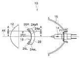
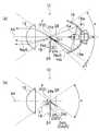
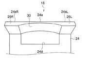
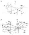
図1は本発明の一実施形態である車両用灯具10を、その光軸AXを含む水平面で切断した断面図、図2(a)は図1に示した車両用灯具10を、その光軸AXを含む鉛直面で切断した断面図、図2(b)は図1に示した車両用灯具10のA−A断面図、図3は光源14の例、図4は前側反射面26L、26R及び後側反射面28の斜視図、図5はシェード18の正面図、図6(a)は図1に示した車両用灯具10のB−B断面図、図6(b)は図1に示した車両用灯具10のA−A断面図、図7は車両用灯具10により形成される配光パターンP1、P2の例である。  FIG. 1 is a cross-sectional view of avehicular lamp 10 according to an embodiment of the present invention, cut along a horizontal plane including its optical axis AX, and FIG. 2 (a) shows thevehicular lamp 10 shown in FIG. FIG. 2B is a cross-sectional view taken along a line AA of thevehicular lamp 10 shown in FIG. 1, FIG. 3 is an example of thelight source 14, and FIG. 4 is a front reflectingsurface 26L, 26R. 5 is a front view of theshade 18, FIG. 6A is a cross-sectional view of thevehicular lamp 10 shown in FIG. 1, and FIG. 6B is FIG. FIG. 7 is an example of light distribution patterns P1 and P2 formed by thevehicular lamp 10. FIG.

本実施形態の車両用灯具10は、図1、図2(a)、図2(b)に示すように、ロービーム用配光パターンを形成するプロジェクタ型の灯具ユニットであり、車両前後方向に延びる光軸AX上に配置された投影レンズ12、投影レンズ12の後側焦点Fより後方に配置された光源14、光源14からの光を前方に向けて光軸AX寄りに反射させる反射面16、投影レンズ12と光源14との間に配置され、反射面16で反射される光源14からの光のうち投影レンズ12を透過して上向きに照射される光を遮光するシェード18等を備えている。  Thevehicle lamp 10 of the present embodiment is a projector-type lamp unit that forms a low-beam light distribution pattern as shown in FIGS. 1, 2A, and 2B, and extends in the vehicle front-rear direction. Aprojection lens 12 disposed on the optical axis AX, alight source 14 disposed behind the rear focal point F of theprojection lens 12, a reflectingsurface 16 that reflects light from thelight source 14 toward the front toward the optical axis AX, Ashade 18 is disposed between theprojection lens 12 and thelight source 14 and shields the light emitted from thelight source 14 reflected by the reflectingsurface 16 through theprojection lens 12 and irradiated upward. .

投影レンズ12は、前方側表面が凸面で後方側表面が平面の平凸レンズであり、ホルダ(図示せず)により保持されて、光軸AX上に配置されている。  Theprojection lens 12 is a plano-convex lens having a convex front surface and a flat rear surface. Theprojection lens 12 is held on a holder (not shown) and disposed on the optical axis AX.

光源14は、その中心から全方向へ光を放出する光源であり、例えば、ハロゲン電球、HID電球である。光源14は、その中心から全方向へ光を放出する光源であればよく、その構造は特に問わない。例えば、光源14は、図3に示すように、半球方向に光を放出する半導体発光素子(例えば、LED(発光ダイオード)やLD(レーザーダイオード)を用いた2つの光源20、20、例えば、LEDと蛍光体とを組み合わせた構造の白色光源(又は、LDと蛍光体とを組み合わせた構造の白色光源)の背面同士が基板22を間に挟んで対向した構造の光源、その他構造の光源であってもよい。  Thelight source 14 is a light source that emits light in all directions from the center thereof, and is, for example, a halogen bulb or an HID bulb. Thelight source 14 may be any light source that emits light from its center in all directions, and its structure is not particularly limited. For example, as shown in FIG. 3, thelight source 14 includes twolight sources 20 and 20, for example, LEDs using semiconductor light emitting elements (for example, LEDs (light emitting diodes) and LDs (laser diodes)) that emit light in a hemispherical direction. A light source having a structure in which the back surface of a white light source having a structure in which a phosphor and a phosphor are combined (or a white light source having a structure in which an LD and a phosphor are combined) are opposed to each other with asubstrate 22 therebetween, and a light source having another structure. May be.

反射面16は、第1焦点F1が光源14又はその近傍に設定され、第2焦点F2が投影レンズ12の後側焦点F又はその近傍に設定された回転楕円系の反射面(回転楕円面又はこれに類する自由曲面等)である。  Thereflection surface 16 has a spheroid reflection surface (a spheroid or spheroid surface) in which the first focal point F1 is set at or near thelight source 14 and the second focal point F2 is set at or behind the rear focal point F of theprojection lens 12. A similar free-form surface).

図2(a)に示すように、反射面16は、投影レンズ12の光取り込み角αに対応する基本反射領域16aと、投影レンズ12の光取り込み角αの下方外側に延長された延長反射領域16b(角度βに対応する延長反射領域16b)と、を含んでいる。なお、光取り込み角αとは、投影レンズ12(有効径)の径方向両端と投影レンズ12の焦点Fとを結んだ2本の直線がなす角度のことである。  As shown in FIG. 2A, thereflection surface 16 includes abasic reflection region 16a corresponding to the light capturing angle α of theprojection lens 12, and an extended reflection region extended outwardly below the light capturing angle α of theprojection lens 12. 16b (extendedreflection region 16b corresponding to the angle β). The light capture angle α is an angle formed by two straight lines connecting the radial ends of the projection lens 12 (effective diameter) and the focal point F of theprojection lens 12.

図1、図2(a)、図2(b)、図4、図5に示すように、シェード18は、投影レンズ12の後側焦点F又はその近傍を通り、投影レンズ12の焦点面に沿って左右段違いで水平方向に延びる上端縁24aを含むシェード本体24と、上端縁24aの両端部24aL、24aRから前方に向かって斜め下方に延びる前側延長部24bL、24bRの上面に形成された前側反射面26L、26Rと、上端縁24aから後方に向かって斜め下方に延びる後側延長部24cの上面に形成された後側反射面28と、後側延長部24cの下面に形成された内側反射面30と、を備えている。シェード本体24の上端部には、内側反射面30で反射された反射面16(延長反射領域16b)からの反射光が通過する貫通穴24dが形成されている(図2(a)、図5参照)。  As shown in FIGS. 1, 2 (a), 2 (b), 4, and 5, theshade 18 passes through or behind the rear focal point F of theprojection lens 12 and is on the focal plane of theprojection lens 12. Ashade body 24 including anupper end edge 24a extending horizontally in a horizontal direction along the left and right sides, and a front side formed on the upper surface of front extension parts 24bL and 24bR extending obliquely downward from both ends 24aL and 24aR of theupper end edge 24a toward the front. Reflectingsurfaces 26L and 26R, arear reflecting surface 28 formed on the upper surface of therear extension 24c extending obliquely downward from theupper edge 24a, and an inner reflection formed on the lower surface of therear extension 24c. And asurface 30. A throughhole 24d through which reflected light from the reflection surface 16 (extendedreflection region 16b) reflected by the inner reflection surface 30 passes is formed at the upper end of the shade body 24 (FIGS. 2A and 5). reference).

前側反射面26L、26Rは、鉛直断面が直線で(図2(b)参照)、水平断面が上端縁24aに沿って湾曲した曲面形状の反射面であり(図1、図4参照)、例えば、上端縁24aの両端部24aL、24aRから前方に向かって斜め下方に延びたシェード18の前側延長部24bL、24bRの上面に対して鏡面研磨又はアルミ等の金属蒸着を施すことで形成されている。あるいは、シェード18の前側延長部24bL、24bRの上面に薄い板状の反射板を貼り付けることで形成してもよい。前側反射面26L、26Rは、鉛直断面が直線に限られず、曲線であってもよい。前側反射面26L、26Rの鉛直断面の形状(及び/又は水平断面の形状)を調整することで、水平線H−Hより上の左右側方領域の高さ寸法(及び/又は水平方向寸法)を調整することが可能となる。  Thefront reflecting surfaces 26L and 26R are curved reflecting surfaces whose vertical cross section is a straight line (see FIG. 2B) and whose horizontal cross section is curved along theupper edge 24a (see FIGS. 1 and 4). The upper surfaces of the front extension portions 24bL and 24bR of theshade 18 extending obliquely downward from the both end portions 24aL and 24aR of theupper edge 24a are subjected to mirror polishing or metal deposition such as aluminum. . Or you may form by sticking a thin plate-shaped reflecting plate on the upper surface of the front side extension parts 24bL and 24bR of theshade 18. Thefront reflecting surfaces 26L and 26R are not limited to straight lines in the vertical section, but may be curved. By adjusting the shape of the vertical cross section (and / or the shape of the horizontal cross section) of thefront reflecting surfaces 26L and 26R, the height dimension (and / or the horizontal dimension) of the left and right side regions above the horizontal line H-H is adjusted. It becomes possible to adjust.

図2(b)に示すように、前側反射面26L、26Rの水平面に対する傾斜角度θ1は、光源14から全方向へ放出されて投影レンズ12へ入射する光(例えば、図6(a)、図6(b)中、光軸AXより上の基本反射領域16aで反射されるRay1参照)の進路を遮らないように、投影レンズ12の光取り込み角α/2以上の角度とされている。すなわち、前側反射面26L、26Rは、光源14から全方向へ放出されて投影レンズ12へ入射する光(例えば、図6(a)、図6(b)中、光軸AXより上の基本反射領域16aで反射されるRay1参照)の進路を遮らないように、投影レンズ12の光取り込み角αの下方外側において、前方斜め下方に延びている。  As shown in FIG. 2B, the inclination angle θ1 of the frontreflective surfaces 26L and 26R with respect to the horizontal plane is light emitted from thelight source 14 in all directions and incident on the projection lens 12 (for example, FIG. 6A and FIG. In FIG. 6 (b), theprojection lens 12 has an angle greater than or equal to the light capturing angle α / 2 so as not to block the course ofRay 1 reflected by thebasic reflection region 16a above the optical axis AX. That is, the frontreflective surfaces 26L and 26R are light emitted from thelight source 14 in all directions and incident on the projection lens 12 (for example, basic reflection above the optical axis AX in FIGS. 6A and 6B). In order not to block the course ofRay 1 reflected by theregion 16a), theprojection lens 12 extends obliquely forward and downward on the outer side below the light capturing angle α.

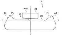
上記構成の前側反射面26L、26Rによれば、光源14から全方向へ放出され、前側反射面26L、26Rへあらゆる方向から入射する光(例えば、図6(b)中、光軸AXより上の基本反射領域16aで反射されて比較的きつい角度で入射するRay2参照)は、当該前側反射面26L、26Rで反射されて投影レンズ12を透過し、車両前面に正対する仮想鉛直スクリーン上の水平線H−Hより上の左右側方領域AL、ARを照射する付加配光パターンPL、PRを形成する(図7参照)。なお、左右側方領域AL、ARを照射する付加配光パターンPL、PRの鉛直方向寸法は、前側反射面26L、26Rの長さ及び/又は前側反射面26L、26Rの水平面に対する傾斜角度θ1を調整することで、調整可能である。また、左右側方領域AL、ARを照射する付加配光パターンPL、PRの水平方向寸法は、前側反射面26L、26Rの水平方向寸法を調整することで、調整可能である。  According to the front reflection surfaces 26L and 26R having the above-described configuration, light emitted from thelight source 14 in all directions and incident on the front reflection surfaces 26L and 26R from all directions (for example, above the optical axis AX in FIG. 6B). The horizontal line on the virtual vertical screen that is reflected by thebasic reflection region 16a and incident at a relatively tight angle is reflected by thefront reflecting surfaces 26L and 26R, passes through theprojection lens 12, and faces the front of the vehicle. Additional light distribution patterns PL and PR for irradiating the left and right side areas AL and AR above HH are formed (see FIG. 7). The vertical dimensions of the additional light distribution patterns PL and PR that irradiate the left and right side areas AL and AR are the lengths of thefront reflecting surfaces 26L and 26R and / or the inclination angle θ1 of thefront reflecting surfaces 26L and 26R with respect to the horizontal plane. It can be adjusted by adjusting. Further, the horizontal dimension of the additional light distribution patterns PL and PR that irradiate the left and right side areas AL and AR can be adjusted by adjusting the horizontal dimension of thefront reflecting surfaces 26L and 26R.

なお、前側反射面26L、26Rは、水平線H−Hより上の左右9度より外側に対応する範囲に設けるのが望ましい。このようにすれば、水平線H−Hより上の左右9度より外側の左右側方領域AL、ARのみを照射し、左右側方領域AL、ARの間の領域を照射しない付加配光パターンPL、PRを形成することが可能となる。前側反射面26L、26Rを左右9度より外側に対応する範囲に設ける理由は、仮に前側反射面26L、26Rを左右9度より内側に対応する範囲に設けると、その反射光が対向車又は先行車に対してグレアを与えることとなるため、これを防止するためである(ECE規則では、左右9度より内側にグレアが存在しないことが求められている)。  Thefront reflecting surfaces 26L and 26R are desirably provided in a range corresponding to the outside of the left and right 9 degrees above the horizontal line HH. In this way, the additional light distribution pattern PL that irradiates only the left and right side areas AL and AR outside the left and right 9 degrees above the horizontal line H-H and does not irradiate the area between the left and right side areas AL and AR. , PR can be formed. The reason why the frontreflective surfaces 26L and 26R are provided in the range corresponding to the outside of the left and right 9 degrees is that if the frontreflective surfaces 26L and 26R are provided in the range corresponding to the inside of the 9 degrees and the reflected light This is to prevent glare from being imparted to the car (the ECE rule requires that there is no glare inside 9 degrees from the left and right).

後側反射面28は、鉛直断面が直線で(図2(a)、図2(b)参照)、水平断面が上端縁24aに沿って湾曲した曲面形状の反射面であり(図1、図4参照)、例えば、上端縁24aから後方に向かって斜め下方に延びたシェード18の後側延長部24cの上面に対して鏡面研磨又はアルミ等の金属蒸着を施すことで形成されている。あるいは、シェード18の後側延長部24cの上面に薄い板状の反射板を貼り付けることで形成してもよい。後側反射面28は、鉛直断面が直線に限られず、曲線であってもよい。  Therear reflecting surface 28 is a reflecting surface having a curved shape in which the vertical cross section is a straight line (see FIGS. 2A and 2B) and the horizontal cross section is curved along theupper edge 24a (see FIGS. 1 and 2). 4), for example, by performing mirror polishing or metal deposition such as aluminum on the upper surface of therear extension 24c of theshade 18 extending obliquely downward from theupper edge 24a to the rear. Or you may form by sticking a thin plate-shaped reflecting plate on the upper surface of the rearside extension part 24c of theshade 18. Therear reflecting surface 28 is not limited to a straight section in the vertical section, but may be a curved line.

図2(a)に示すように、後側反射面28の水平面に対する傾斜角度θ2は、光源14から全方向へ放出されて投影レンズ12へ入射する光(例えば、図6(a)、図6(b)中、光軸AXより下の基本反射領域16aで反射される光Ray3参照)の進路を遮らないように、投影レンズ12の光取り込み角α/2以上の角度とされている。すなわち、後側反射面28は、光源14から全方向へ放出されて投影レンズ12へ入射する光(例えば、図6(a)、図6(b)中、光軸AXより下の基本反射領域16aで反射される光Ray3参照)の進路を遮らないように、投影レンズ12の光取り込み角αの下方外側において、前方斜め下方に延びている。  As shown in FIG. 2A, the inclination angle θ2 of the rearreflective surface 28 with respect to the horizontal plane is light emitted from thelight source 14 in all directions and incident on the projection lens 12 (for example, FIG. 6A and FIG. 6). In (b), theprojection lens 12 is set to an angle equal to or larger than the light capturing angle α / 2 so as not to block the path of the light Ray 3 reflected by thebasic reflection region 16a below the optical axis AX. That is, the rearreflective surface 28 is emitted from thelight source 14 in all directions and is incident on the projection lens 12 (for example, a basic reflection region below the optical axis AX in FIGS. 6A and 6B). 16a. Theprojection lens 12 extends obliquely forward and downward on the outer side below the light capturing angle α of theprojection lens 12 so as not to obstruct the path of the light Ray 3 reflected by the light 16a.

上記構成の後側反射面28によれば、光源14から全方向へ放出され、後側反射面28へあらゆる方向から入射する光のうち少なくとも一部(例えば、図6(b)中、光軸AXより上の基本反射領域16aで反射されて比較的浅い角度で入射するRay4参照)は、当該後側反射面28で反射されて投影レンズ12を透過して屈折し、路面方向に向かう。すなわち、光源14から全方向へ放出され、後側反射面28へあらゆる方向から入射する光のうち少なくとも一部(例えば、図6(b)中、光軸AXより下の基本反射領域16aで反射されて比較的浅い角度で入射するRay4参照)は、上端縁24a(カットオフラインCL)を境に折り返されてカットオフラインCL以下の基本配光パターンP1に重畳される形となる。これにより、車両用灯具10の光利用効率を高めることが可能となる。  According to the rearreflective surface 28 having the above-described configuration, at least part of light emitted from thelight source 14 in all directions and incident on the rearreflective surface 28 from all directions (for example, the optical axis in FIG. 6B). The Ray 4 reflected from thebasic reflection region 16a above the AX and incident at a relatively shallow angle is reflected by therear reflecting surface 28, refracted through theprojection lens 12, and travels in the road surface direction. That is, at least a part of light emitted from thelight source 14 in all directions and incident on the rearreflective surface 28 from all directions (for example, reflected by thebasic reflection region 16a below the optical axis AX in FIG. 6B). The Ray 4 that is incident at a relatively shallow angle is folded back at theupper edge 24a (cut-off line CL) and superimposed on the basic light distribution pattern P1 below the cut-off line CL. Thereby, the light utilization efficiency of thevehicular lamp 10 can be increased.

内側反射面30は、シェード18の後側延長部24cの下面のうち、オーバーヘッドサイン領域(例えば、水平線H−Hより上0〜4度、左右9度の範囲)に対応する範囲に設定されている。内側反射面30は、鉛直断面が直線で(図2(a)参照)、水平断面が凹状に湾曲した曲面形状の反射面であり(図5参照)、例えば、上端縁24aから後方に向かって斜め下方に延びたシェード18の後側延長部24cの下面に対して鏡面研磨又はアルミ等の金属蒸着を施すことで形成されている。あるいは、シェード18の後側延長部24cの下面に薄い板状の反射板を貼り付けることで形成してもよい。内側反射面30は、鉛直断面が直線に限られず、曲線であってもよい。  Theinner reflection surface 30 is set to a range corresponding to an overhead sign region (for example, a range of 0 to 4 degrees above the horizontal line HH and 9 degrees on the left and right) of the lower surface of therear extension 24c of theshade 18. Yes. Theinner reflecting surface 30 is a curved reflecting surface having a straight vertical cross section (see FIG. 2A) and a horizontal cross section curved in a concave shape (see FIG. 5), for example, from theupper edge 24a toward the rear. It is formed by mirror polishing or metal deposition such as aluminum on the lower surface of therear extension 24c of theshade 18 extending obliquely downward. Or you may form by sticking a thin plate-shaped reflection board on the lower surface of the rearside extension part 24c of theshade 18. FIG. The innerreflective surface 30 is not limited to a straight cross section, and may be a curved line.

上記のように、内側反射面30の水平断面を凹状に湾曲した曲面形状とすることで、シェード18の後側延長部24cを、中央部が薄肉で両端部(図5中、左右方向の両端部)が厚肉の成形しやすい構造とすることが可能となる。換言すれば、上記のように、内側反射面30の水平断面を湾曲した曲面形状とすることで、シェード18(後側延長部24c)の強度を保ちながら、オーバーヘッドサイン領域AOHを照射するオーバーヘッド配光パターンP2を形成することが可能となる。As described above, by making the horizontal cross section of theinner reflection surface 30 into a curved shape that is curved in a concave shape, therear extension 24c of theshade 18 is thin at the center and has both ends (both ends in the left-right direction in FIG. 5). Part) can be made thick and easy to mold. In other words, as described above, by the curved shape curved horizontal cross-section of theinner reflecting surface 30, while maintaining the strength of the shade 18 (the rearside extension portion 24c), it illuminates an overhead sign region AOH overhead The light distribution pattern P2 can be formed.

上記構成の内側反射面30によれば、光源14から全方向へ放出され、反射面16(延長反射領域16b)で反射されて内側反射面30へ入射する光(例えば、図2(a)中、Ray5参照)は、当該内側反射面30で反射されてシェード本体24に形成された貫通穴24d(図2(a)、図5参照)を通過し、投影レンズ12を透過して屈折し、前方斜め上方へ照射されてオーバーヘッドサイン領域AOHを照射するオーバーヘッド配光パターンP2を形成する(図7参照)。According to theinner reflection surface 30 having the above configuration, light emitted from thelight source 14 in all directions, reflected by the reflection surface 16 (extendedreflection region 16b), and incident on the inner reflection surface 30 (for example, in FIG. 2A). , Ray 5) is reflected by theinner reflection surface 30 and passes through the throughhole 24d (see FIGS. 2A and 5) formed in theshade body 24, passes through theprojection lens 12, and is refracted. irradiated forward obliquely upward to form an overhead light distribution pattern P2 for irradiating an overhead sign region aOH (see FIG. 7).

反射面16(延長反射領域16b)で反射される光(例えば、図2(a)中、Ray5参照)は、投影レンズ12の光取り込み角αの下方外側を進行する光であり、本来、投影レンズ12へ入射せず基本配光パターンP1に寄与しない光である。  The light reflected by the reflection surface 16 (extendedreflection region 16b) (see, for example, Ray5 in FIG. 2A) is light that travels outside the light capturing angle α of theprojection lens 12, and is originally projected. The light does not enter thelens 12 and does not contribute to the basic light distribution pattern P1.

これに対して、上記構成の内側反射面30によれば、内側反射面30の作用により、反射面16(延長反射領域16b)で反射される光(例えば、図2(a)中、Ray5参照)を反射させてシェード本体24に形成された貫通穴24d(図2(a)、図5参照)を通過させ、投影レンズ12を透過させ、オーバーヘッドサイン領域AOHを照射するオーバーヘッド配光パターンP2を形成することが可能となる。これにより、車両用灯具10の光利用効率を高めることが可能となる。On the other hand, according to theinner reflection surface 30 having the above-described configuration, the light reflected by the reflection surface 16 (extendedreflection region 16b) by the action of the inner reflection surface 30 (for example, see Ray5 in FIG. 2A). ) through-holes 24d formed in the shademain body 24 by reflecting (FIG. 2 (a), FIG. 5) to pass through and is transmitted through theprojection lens 12, an overhead sign region aOH overhead light distribution irradiates the pattern P2 Can be formed. Thereby, the light utilization efficiency of thevehicular lamp 10 can be increased.

上記構成の車両用灯具10によれば、図2(a)に示すように、光源14から全方向へ放出された光は、反射面16(基本反射領域16a)で反射され、前側反射面26L、26R及び後側反射面28で遮られることなく、投影レンズ12の後側焦点F近傍に集光するとともに、一部(投影レンズ12を透過して上向きに照射される光)がシェード18により遮光された後、投影レンズ12を透過して前方に照射され、車両前面に正対した仮想鉛直スクリーン(例えば、車両前方約25mに配置されている)上に、シェード18(上端縁24a)により規定されるカットオフラインCLを含む基本配光パターンP1(ロービーム用配光パターン)を形成する(図7参照)。  According to thevehicular lamp 10 having the above configuration, as shown in FIG. 2A, the light emitted from thelight source 14 in all directions is reflected by the reflection surface 16 (basic reflection region 16a), and thefront reflection surface 26L. , 26R and therear reflecting surface 28, the light is condensed in the vicinity of the rear focal point F of theprojection lens 12, and a part (light irradiated upward through the projection lens 12) is caused by theshade 18. After being shielded from light, it passes through theprojection lens 12 and is irradiated forward, and is placed on a virtual vertical screen (for example, disposed about 25 m ahead of the vehicle) facing the front of the vehicle by a shade 18 (upper edge 24a). A basic light distribution pattern P1 (low beam light distribution pattern) including the defined cut-off line CL is formed (see FIG. 7).

この基本配光パターンP1(ロービーム用配光パターン)には、前側反射面26L、26Rで反射される反射光により形成される付加配光パターンPL、PR、及び、延長反射領域16b及び内側反射面30で二回反射される反射光により形成されるオーバーヘッド配光パターンP2が付加される(図7参照)。  The basic light distribution pattern P1 (low beam light distribution pattern) includes additional light distribution patterns PL and PR formed by reflected light reflected by the frontreflective surfaces 26L and 26R, and the extendedreflective region 16b and the inner reflective surface. An overhead light distribution pattern P2 formed by the reflected light reflected twice at 30 is added (see FIG. 7).

以上説明したように、本実施形態の車両用灯具10によれば、光源14から放出された光が、基本反射領域16a(従来の基本配光パターンを形成する光を反射する領域に相当)ではなく、投影レンズ12の光取り込み角αの下方外側に延長された延長反射領域16b及び内側反射面30で二回反射し、シェード18の上端部に形成された貫通穴24dを通過し、投影レンズ12を透過して前方斜め上方へ照射され、車両前面に正対する仮想鉛直スクリーン上のオーバーヘッドサイン領域AOHを照射するオーバーヘッド配光パターンP2を形成する構成であるため、基本配光パターンP1を形成する光を反射する領域(基本反射領域16a)を浸食することなく、基本配光パターンP1及びオーバーヘッド配光パターンP2を形成することが可能となる。As described above, according to thevehicular lamp 10 of the present embodiment, the light emitted from thelight source 14 is in thebasic reflection region 16a (corresponding to the region that reflects the light forming the conventional basic light distribution pattern). And reflected twice by theextended reflection region 16b and theinner reflection surface 30 that extend to the lower outside of the light capturing angle α of theprojection lens 12, pass through the throughhole 24d formed in the upper end portion of theshade 18, and irradiated forward obliquely upward through the 12, because it is configured to form an overhead light distribution pattern P2 for irradiating an overhead sign region aOH on the virtual vertical screen directly facing the vehicle front, form the basic light distribution pattern P1 The basic light distribution pattern P1 and the overhead light distribution pattern P2 are formed without eroding the area that reflects the light to be reflected (basic reflection area 16a). It can become.

また、本実施形態の車両用灯具10によれば、上端縁24aのうち両端部24L、24Rから前方に向かって斜め下方に延びる前側反射面26L、26Rの作用により、光源14から全方向へ放出されて当該前側反射面26L、26Rへあらゆる方向から入射する光(例えば、図6(b)中、光軸AXより上の基本反射領域16aで反射されて比較的きつい角度で入射するRay2参照)を反射して投影レンズ12を透過させることで、水平線H−Hより上の左右側方領域AL、ARのみを照射し、左右側方領域AL、ARの間の領域を照射しない付加配光パターンPL、PRが付加された、シェード18(上端縁24a)により規定されるカットオフラインCLを含む基本配光パターンP1を形成することが可能となる(前側反射面26L、26R間に前側反射面は存在しないため、左右側方領域AL、AR間の領域は照射されない)。  Further, according to thevehicular lamp 10 of the present embodiment, the light is emitted from thelight source 14 in all directions by the action of thefront reflecting surfaces 26L and 26R extending obliquely downward from the both ends 24L and 24R of theupper edge 24a. The light incident on thefront reflecting surfaces 26L and 26R from all directions (see, for example, Ray 2 reflected in thebasic reflection region 16a above the optical axis AX and incident at a relatively tight angle in FIG. 6B). Is reflected and transmitted through theprojection lens 12 to irradiate only the left and right side areas AL and AR above the horizontal line H-H, and does not irradiate the area between the left and right side areas AL and AR. It is possible to form a basic light distribution pattern P1 including a cut-off line CL defined by the shade 18 (upper edge 24a) to which PL and PR are added (thefront reflection surface 26L). Because no existing the front reflective surface between 26R, left and right side regions AL, regions between AR is not irradiated).

以上のように、本実施形態の車両用灯具10によれば、水平線H−Hより上の左右側方領域AL、ARのみを照射し、左右側方領域AL、ARの間の領域を照射しない付加配光パターンPL、PRが付加されるため、対向車や先行車に対するグレアを抑えつつ、水平線H−Hより上の左右側方領域AL、ARに存在する歩行者や障害物等を照明することが可能となる。  As described above, according to thevehicle lamp 10 of the present embodiment, only the left and right side areas AL and AR above the horizontal line H-H are irradiated, and the area between the left and right side areas AL and AR is not irradiated. Since the additional light distribution patterns PL and PR are added, pedestrians and obstacles existing in the left and right side areas AL and AR above the horizontal line H-H are illuminated while suppressing glare for oncoming vehicles and preceding vehicles. It becomes possible.

前側反射面26L、26Rへ比較的きつい角度で入射する光(例えば、図6(b)中のRay2参照)は、投影レンズ12の光取り込み角αの上方外側を進行する光であり、本来、投影レンズ12へ入射せず基本配光パターンP1に寄与しない光である(図6(b)点線参照)。  Light that is incident on thefront reflecting surfaces 26L and 26R at a relatively tight angle (see, for example, Ray2 in FIG. 6B) is light that travels outside the light capturing angle α of theprojection lens 12, and is inherently The light does not enter theprojection lens 12 and does not contribute to the basic light distribution pattern P1 (see the dotted line in FIG. 6B).

これに対して、本実施形態の車両用灯具10によれば、前側反射面26L、26Rの作用により、前側反射面26L、26Rへ比較的きつい角度で入射する光(例えば、図6(b)中のRay2参照)を反射させて投影レンズ12を透過させ、付加配光パターンPL、PRの形成に用いることが可能となる。これにより、車両用灯具10の光利用効率を高めることが可能となる。  On the other hand, according to thevehicular lamp 10 of the present embodiment, light incident on the frontreflective surfaces 26L and 26R at a relatively tight angle by the action of the frontreflective surfaces 26L and 26R (for example, FIG. 6B). It can be used for forming the additional light distribution patterns PL and PR. Thereby, the light utilization efficiency of thevehicular lamp 10 can be increased.

また、本実施形態の車両用灯具10によれば、上端縁24aから後方に向かって斜め下方に延びる後側反射面28の作用により、光源14から全方向へ放出されて当該後側反射面28にあらゆる方向から入射する光のうち少なくとも一部(例えば、図6(b)中、光軸AXより上の基本反射領域16aで反射されて比較的浅い角度で入射するRay4参照)を反射して投影レンズ12を透過させ、前方に照射することが可能となるため、車両用灯具10の光利用効率を高めることが可能となる。  Further, according to thevehicular lamp 10 of the present embodiment, the rearreflective surface 28 is emitted from thelight source 14 in all directions by the action of the rearreflective surface 28 extending obliquely downward from theupper edge 24a to the rear. At least a part of light incident from all directions (for example, Ray 4 reflected by thebasic reflection region 16a above the optical axis AX and incident at a relatively shallow angle in FIG. 6B) is reflected. Since theprojection lens 12 can be transmitted and irradiated forward, the light use efficiency of thevehicular lamp 10 can be increased.

上記実施形態はあらゆる点で単なる例示にすぎない。これらの記載によって本発明は限定的に解釈されるものではない。本発明はその精神または主要な特徴から逸脱することなく他の様々な形で実施することができる。  The above embodiment is merely an example in all respects. The present invention is not construed as being limited to these descriptions. The present invention can be implemented in various other forms without departing from the spirit or main features thereof.

10…車両用灯具、12…投影レンズ、14…光源、16…反射面、18…シェード、24…上端縁、26L、26R…前側反射面、28…後側反射面  DESCRIPTION OFSYMBOLS 10 ... Vehicle lamp, 12 ... Projection lens, 14 ... Light source, 16 ... Reflection surface, 18 ... Shade, 24 ... Upper edge, 26L, 26R ... Front side reflection surface, 28 ... Rear side reflection surface

Claims (2)

Translated fromJapanese
車両前後方向に延びる光軸上に配置された投影レンズと、前記投影レンズの後側焦点より後方に配置された光源と、前記光源からの光を前方に向けて前記光軸寄りに反射させる反射面と、前記投影レンズと前記光源との間に配置され、前記反射面で反射される前記光源からの光のうち前記投影レンズを透過して上向きに照射される光を遮光するシェードと、を備え、前記シェードにより規定されるカットオフラインを含む基本配光パターンを形成する車両用灯具において、
前記光源は、その中心から全方向へ光を放出する光源であり、
前記反射面は、前記投影レンズの光取り込み角に対応する基本反射領域と、前記投影レンズの光取り込み角の下方外側に延長された延長反射領域と、を含んでおり、
前記シェードは、前記投影レンズの後側焦点又はその近傍を通り、前記投影レンズの焦点面に沿って水平方向に延びる上端縁を含むシェード本体と、前記上端縁から後方に向かって斜め下方に延びる後側延長部と、前記後側延長部の上面に形成された後側反射面と、前記後側延長部の下面に形成された内側反射面と、を備えており、
前記シェード本体の上端部には、前記内側反射面で反射された前記延長反射領域からの反射光が通過する貫通穴が形成されており、
前記内側反射面で反射された前記延長反射領域からの反射光が、前記貫通穴を通過し、前記投影レンズを透過して前方斜め上方へ照射され、車両前面に正対する仮想鉛直スクリーン上のオーバーヘッドサイン領域を照射するオーバーヘッド配光パターンを形成することを特徴とする車両用灯具。
A projection lens disposed on an optical axis extending in the longitudinal direction of the vehicle, a light source disposed behind a rear focal point of the projection lens, and a reflection that reflects light from the light source forward and closer to the optical axis And a shade that is disposed between the projection lens and the light source, and shields light that passes through the projection lens and is irradiated upward from light from the light source reflected by the reflection surface. A vehicular lamp that forms a basic light distribution pattern including a cut-off line defined by the shade,
The light source is a light source that emits light in all directions from its center,
The reflection surface includes a basic reflection region corresponding to a light capture angle of the projection lens, and an extended reflection region extended to the lower outside of the light capture angle of the projection lens,
The shade passes through or near the rear focal point of the projection lens, and includes a shade body including an upper end edge that extends in the horizontal direction along the focal plane of the projection lens, and extends obliquely downward from the upper edge toward the rear. A rear extension, a rear reflective surface formed on the upper surface of the rear extension, and an inner reflective surface formed on the lower surface of the rear extension,
A through-hole through which reflected light from the extended reflection area reflected by the inner reflection surface passes is formed at the upper end of the shade body,
Reflected light from the extended reflection area reflected by the inner reflection surface passes through the through-hole, passes through the projection lens, is irradiated obliquely forward and upward, and is overhead on a virtual vertical screen facing the front of the vehicle. A vehicular lamp characterized by forming an overhead light distribution pattern for irradiating a sign area.
前記シェードは、前記上端縁の両端部から前方に向かって斜め下方に延びる前側延長部の上面に形成された反射面であって、これに入射した前記光源からの光を反射して前記投影レンズを透過させ、車両前面に正対する仮想鉛直スクリーン上の水平線より上の左右側方領域を照射し、前記基本配光パターンに付加される付加配光パターンを形成する前側反射面と、を備えることを特徴とする請求項1に記載の車両用灯具。  The shade is a reflection surface formed on an upper surface of a front extension extending obliquely downward from both end portions of the upper end edge, and reflects light from the light source incident thereon to reflect the projection lens. A front-side reflecting surface that irradiates left and right lateral regions above a horizontal line on a virtual vertical screen that directly faces the front of the vehicle and forms an additional light distribution pattern added to the basic light distribution pattern. The vehicular lamp according to claim 1.
JP2012067883A2012-03-232012-03-23Vehicular lamp fittingPendingJP2013200981A (en)

Priority Applications (3)

Application NumberPriority DateFiling DateTitle
JP2012067883AJP2013200981A (en)2012-03-232012-03-23Vehicular lamp fitting
US13/846,803US8956029B2 (en)2012-03-232013-03-18Vehicle lighting unit
KR1020130029842AKR102006319B1 (en)2012-03-232013-03-20Vehicle lighting unit

Applications Claiming Priority (1)

Application NumberPriority DateFiling DateTitle
JP2012067883AJP2013200981A (en)2012-03-232012-03-23Vehicular lamp fitting

Publications (1)

Publication NumberPublication Date
JP2013200981Atrue JP2013200981A (en)2013-10-03

Family

ID=49546738

Family Applications (1)

Application NumberTitlePriority DateFiling Date
JP2012067883APendingJP2013200981A (en)2012-03-232012-03-23Vehicular lamp fitting

Country Status (1)

CountryLink
JP (1)JP2013200981A (en)

Cited By (6)

* Cited by examiner, † Cited by third party
Publication numberPriority datePublication dateAssigneeTitle
JP2014203513A (en)*2013-04-012014-10-27株式会社小糸製作所Vehicle lighting appliance
KR101557112B1 (en)2014-04-222015-10-02에스엘 주식회사Lamp for vehicle
US9410671B2 (en)2014-03-272016-08-09Hyundai Motor CompanyHead lamp for vehicle
US9447941B2 (en)2014-03-132016-09-20Sl CorporationLamp for vehicle
CN111288410A (en)*2018-12-072020-06-16深圳市绎立锐光科技开发有限公司 A lighting device and a vehicle using the same
CN112664899A (en)*2015-05-222021-04-16三菱电机株式会社Headlight module

Citations (5)

* Cited by examiner, † Cited by third party
Publication numberPriority datePublication dateAssigneeTitle
JP2001035218A (en)*1999-07-192001-02-09Koito Mfg Co LtdHeadlamp for vehicle
JP2007294203A (en)*2006-04-242007-11-08Koito Mfg Co LtdVehicular headlamp
JP2008198483A (en)*2007-02-132008-08-28Koito Mfg Co LtdVehicle headlight
JP2010108728A (en)*2008-10-302010-05-13Koito Mfg Co LtdVehicular lamp unit and vehicular lamp
JP2011146213A (en)*2010-01-142011-07-28Koito Mfg Co LtdHeadlamp for vehicle

Patent Citations (5)

* Cited by examiner, † Cited by third party
Publication numberPriority datePublication dateAssigneeTitle
JP2001035218A (en)*1999-07-192001-02-09Koito Mfg Co LtdHeadlamp for vehicle
JP2007294203A (en)*2006-04-242007-11-08Koito Mfg Co LtdVehicular headlamp
JP2008198483A (en)*2007-02-132008-08-28Koito Mfg Co LtdVehicle headlight
JP2010108728A (en)*2008-10-302010-05-13Koito Mfg Co LtdVehicular lamp unit and vehicular lamp
JP2011146213A (en)*2010-01-142011-07-28Koito Mfg Co LtdHeadlamp for vehicle

Cited By (7)

* Cited by examiner, † Cited by third party
Publication numberPriority datePublication dateAssigneeTitle
JP2014203513A (en)*2013-04-012014-10-27株式会社小糸製作所Vehicle lighting appliance
US9447941B2 (en)2014-03-132016-09-20Sl CorporationLamp for vehicle
US9410671B2 (en)2014-03-272016-08-09Hyundai Motor CompanyHead lamp for vehicle
KR101557112B1 (en)2014-04-222015-10-02에스엘 주식회사Lamp for vehicle
CN112664899A (en)*2015-05-222021-04-16三菱电机株式会社Headlight module
CN112664899B (en)*2015-05-222022-10-25三菱电机株式会社Headlight module
CN111288410A (en)*2018-12-072020-06-16深圳市绎立锐光科技开发有限公司 A lighting device and a vehicle using the same

Similar Documents

PublicationPublication DateTitle
JP6052569B2 (en) Vehicle lamp unit
JP6410341B2 (en) Vehicle headlamp
JP4413839B2 (en) Vehicle headlamp lamp unit
JP5848920B2 (en) Vehicle headlamp
KR101393659B1 (en) Car headlight
JP5692521B2 (en) Motorcycle headlights
JP5897913B2 (en) Lamp unit
JP2011040247A (en)Lamp unit of headlight for vehicle
JP2011165600A (en)Vehicular illumination lamp
JP2013200981A (en)Vehicular lamp fitting
JP2008258001A (en)Lamp unit of vehicular headlamp
JP2015076243A (en)Vehicular lighting tool
JP2011025820A (en)Vehicular lighting fixture
JP2010282790A (en) Vehicle lighting
US8956029B2 (en)Vehicle lighting unit
JP2009104790A (en) Vehicle headlamp
JP5958004B2 (en) Vehicle lighting
JP2015002128A (en) Vehicle lighting
JP2012199156A (en) Vehicle headlamp
JP5979414B2 (en) Vehicle lighting
JP2009152056A (en) Vehicle lighting
JP5013080B2 (en) Projector type headlight
JP2007207687A (en) Vehicle lighting
JP6711724B2 (en) Vehicle headlights
JP4587047B2 (en) Vehicle lighting

Legal Events

DateCodeTitleDescription
A621Written request for application examination

Free format text:JAPANESE INTERMEDIATE CODE: A621

Effective date:20150306

A977Report on retrieval

Free format text:JAPANESE INTERMEDIATE CODE: A971007

Effective date:20151126

A131Notification of reasons for refusal

Free format text:JAPANESE INTERMEDIATE CODE: A131

Effective date:20151130

A02Decision of refusal

Free format text:JAPANESE INTERMEDIATE CODE: A02

Effective date:20160323


[8]ページ先頭

©2009-2025 Movatter.jp