JP2013198187A - Vehicle power supply device - Google Patents
Vehicle power supply deviceDownload PDFInfo
- Publication number
- JP2013198187A JP2013198187AJP2012059686AJP2012059686AJP2013198187AJP 2013198187 AJP2013198187 AJP 2013198187AJP 2012059686 AJP2012059686 AJP 2012059686AJP 2012059686 AJP2012059686 AJP 2012059686AJP 2013198187 AJP2013198187 AJP 2013198187A
- Authority
- JP
- Japan
- Prior art keywords
- power
- vehicle
- power supply
- coil
- unit
- Prior art date
- Legal status (The legal status is an assumption and is not a legal conclusion. Google has not performed a legal analysis and makes no representation as to the accuracy of the status listed.)
- Granted
Links
Images


Classifications
- B—PERFORMING OPERATIONS; TRANSPORTING
- B60—VEHICLES IN GENERAL
- B60L—PROPULSION OF ELECTRICALLY-PROPELLED VEHICLES; SUPPLYING ELECTRIC POWER FOR AUXILIARY EQUIPMENT OF ELECTRICALLY-PROPELLED VEHICLES; ELECTRODYNAMIC BRAKE SYSTEMS FOR VEHICLES IN GENERAL; MAGNETIC SUSPENSION OR LEVITATION FOR VEHICLES; MONITORING OPERATING VARIABLES OF ELECTRICALLY-PROPELLED VEHICLES; ELECTRIC SAFETY DEVICES FOR ELECTRICALLY-PROPELLED VEHICLES
- B60L53/00—Methods of charging batteries, specially adapted for electric vehicles; Charging stations or on-board charging equipment therefor; Exchange of energy storage elements in electric vehicles
- B60L53/30—Constructional details of charging stations
- B60L53/35—Means for automatic or assisted adjustment of the relative position of charging devices and vehicles
- B60L53/36—Means for automatic or assisted adjustment of the relative position of charging devices and vehicles by positioning the vehicle
- B—PERFORMING OPERATIONS; TRANSPORTING
- B60—VEHICLES IN GENERAL
- B60L—PROPULSION OF ELECTRICALLY-PROPELLED VEHICLES; SUPPLYING ELECTRIC POWER FOR AUXILIARY EQUIPMENT OF ELECTRICALLY-PROPELLED VEHICLES; ELECTRODYNAMIC BRAKE SYSTEMS FOR VEHICLES IN GENERAL; MAGNETIC SUSPENSION OR LEVITATION FOR VEHICLES; MONITORING OPERATING VARIABLES OF ELECTRICALLY-PROPELLED VEHICLES; ELECTRIC SAFETY DEVICES FOR ELECTRICALLY-PROPELLED VEHICLES
- B60L53/00—Methods of charging batteries, specially adapted for electric vehicles; Charging stations or on-board charging equipment therefor; Exchange of energy storage elements in electric vehicles
- B60L53/10—Methods of charging batteries, specially adapted for electric vehicles; Charging stations or on-board charging equipment therefor; Exchange of energy storage elements in electric vehicles characterised by the energy transfer between the charging station and the vehicle
- B60L53/12—Inductive energy transfer
- B60L53/126—Methods for pairing a vehicle and a charging station, e.g. establishing a one-to-one relation between a wireless power transmitter and a wireless power receiver
- B—PERFORMING OPERATIONS; TRANSPORTING
- B60—VEHICLES IN GENERAL
- B60L—PROPULSION OF ELECTRICALLY-PROPELLED VEHICLES; SUPPLYING ELECTRIC POWER FOR AUXILIARY EQUIPMENT OF ELECTRICALLY-PROPELLED VEHICLES; ELECTRODYNAMIC BRAKE SYSTEMS FOR VEHICLES IN GENERAL; MAGNETIC SUSPENSION OR LEVITATION FOR VEHICLES; MONITORING OPERATING VARIABLES OF ELECTRICALLY-PROPELLED VEHICLES; ELECTRIC SAFETY DEVICES FOR ELECTRICALLY-PROPELLED VEHICLES
- B60L53/00—Methods of charging batteries, specially adapted for electric vehicles; Charging stations or on-board charging equipment therefor; Exchange of energy storage elements in electric vehicles
- B60L53/30—Constructional details of charging stations
- B60L53/34—Plug-like or socket-like devices specially adapted for contactless inductive charging of electric vehicles
- B—PERFORMING OPERATIONS; TRANSPORTING
- B60—VEHICLES IN GENERAL
- B60L—PROPULSION OF ELECTRICALLY-PROPELLED VEHICLES; SUPPLYING ELECTRIC POWER FOR AUXILIARY EQUIPMENT OF ELECTRICALLY-PROPELLED VEHICLES; ELECTRODYNAMIC BRAKE SYSTEMS FOR VEHICLES IN GENERAL; MAGNETIC SUSPENSION OR LEVITATION FOR VEHICLES; MONITORING OPERATING VARIABLES OF ELECTRICALLY-PROPELLED VEHICLES; ELECTRIC SAFETY DEVICES FOR ELECTRICALLY-PROPELLED VEHICLES
- B60L53/00—Methods of charging batteries, specially adapted for electric vehicles; Charging stations or on-board charging equipment therefor; Exchange of energy storage elements in electric vehicles
- B60L53/30—Constructional details of charging stations
- B60L53/35—Means for automatic or assisted adjustment of the relative position of charging devices and vehicles
- B60L53/38—Means for automatic or assisted adjustment of the relative position of charging devices and vehicles specially adapted for charging by inductive energy transfer
- Y—GENERAL TAGGING OF NEW TECHNOLOGICAL DEVELOPMENTS; GENERAL TAGGING OF CROSS-SECTIONAL TECHNOLOGIES SPANNING OVER SEVERAL SECTIONS OF THE IPC; TECHNICAL SUBJECTS COVERED BY FORMER USPC CROSS-REFERENCE ART COLLECTIONS [XRACs] AND DIGESTS
- Y02—TECHNOLOGIES OR APPLICATIONS FOR MITIGATION OR ADAPTATION AGAINST CLIMATE CHANGE
- Y02T—CLIMATE CHANGE MITIGATION TECHNOLOGIES RELATED TO TRANSPORTATION
- Y02T10/00—Road transport of goods or passengers
- Y02T10/60—Other road transportation technologies with climate change mitigation effect
- Y02T10/70—Energy storage systems for electromobility, e.g. batteries
- Y—GENERAL TAGGING OF NEW TECHNOLOGICAL DEVELOPMENTS; GENERAL TAGGING OF CROSS-SECTIONAL TECHNOLOGIES SPANNING OVER SEVERAL SECTIONS OF THE IPC; TECHNICAL SUBJECTS COVERED BY FORMER USPC CROSS-REFERENCE ART COLLECTIONS [XRACs] AND DIGESTS
- Y02—TECHNOLOGIES OR APPLICATIONS FOR MITIGATION OR ADAPTATION AGAINST CLIMATE CHANGE
- Y02T—CLIMATE CHANGE MITIGATION TECHNOLOGIES RELATED TO TRANSPORTATION
- Y02T10/00—Road transport of goods or passengers
- Y02T10/60—Other road transportation technologies with climate change mitigation effect
- Y02T10/7072—Electromobility specific charging systems or methods for batteries, ultracapacitors, supercapacitors or double-layer capacitors
- Y—GENERAL TAGGING OF NEW TECHNOLOGICAL DEVELOPMENTS; GENERAL TAGGING OF CROSS-SECTIONAL TECHNOLOGIES SPANNING OVER SEVERAL SECTIONS OF THE IPC; TECHNICAL SUBJECTS COVERED BY FORMER USPC CROSS-REFERENCE ART COLLECTIONS [XRACs] AND DIGESTS
- Y02—TECHNOLOGIES OR APPLICATIONS FOR MITIGATION OR ADAPTATION AGAINST CLIMATE CHANGE
- Y02T—CLIMATE CHANGE MITIGATION TECHNOLOGIES RELATED TO TRANSPORTATION
- Y02T90/00—Enabling technologies or technologies with a potential or indirect contribution to GHG emissions mitigation
- Y02T90/10—Technologies relating to charging of electric vehicles
- Y02T90/12—Electric charging stations
- Y—GENERAL TAGGING OF NEW TECHNOLOGICAL DEVELOPMENTS; GENERAL TAGGING OF CROSS-SECTIONAL TECHNOLOGIES SPANNING OVER SEVERAL SECTIONS OF THE IPC; TECHNICAL SUBJECTS COVERED BY FORMER USPC CROSS-REFERENCE ART COLLECTIONS [XRACs] AND DIGESTS
- Y02—TECHNOLOGIES OR APPLICATIONS FOR MITIGATION OR ADAPTATION AGAINST CLIMATE CHANGE
- Y02T—CLIMATE CHANGE MITIGATION TECHNOLOGIES RELATED TO TRANSPORTATION
- Y02T90/00—Enabling technologies or technologies with a potential or indirect contribution to GHG emissions mitigation
- Y02T90/10—Technologies relating to charging of electric vehicles
- Y02T90/14—Plug-in electric vehicles
Landscapes
- Engineering & Computer Science (AREA)
- Power Engineering (AREA)
- Transportation (AREA)
- Mechanical Engineering (AREA)
- Computer Networks & Wireless Communication (AREA)
- Charge And Discharge Circuits For Batteries Or The Like (AREA)
- Secondary Cells (AREA)
- Electric Propulsion And Braking For Vehicles (AREA)
Abstract
Translated fromJapaneseDescription
Translated fromJapanese本発明は、車両のバッテリへの充電を行うために、車両に対し車外から給電する車両給電装置に関する。 The present invention relates to a vehicle power supply device that supplies power to a vehicle from the outside in order to charge a battery of the vehicle.
駐車場の輪止めの前方に装置本体を設置し、装置本体から突出させた支持アームの先端に形成された給電側コイルを、車両に設けられた受電側コイル内に下方から挿入して充電電流を印加し、電磁誘導作用によりバッテリを充電する車両充電装置に関する従来技術があった(例えば、特許文献1参照)。特許文献1に記載された車両充電装置は、充電を開始する際に、電磁誘導作用により逆誘起された給電側コイルの交流電流変化を検出することにより、給電側コイルの車幅方向の位置を決定しており、車両に対する給電側コイルの位置精度を向上させることができる。 Install the device main body in front of the parking lock and insert the power supply coil formed at the tip of the support arm that protrudes from the device main body into the power receiving coil provided on the vehicle from below to charge the current. There is a conventional technology related to a vehicle charging device that applies a voltage to charge a battery by electromagnetic induction (see, for example, Patent Document 1). When the vehicle charging device described in
また、フロアに複数の溝を形成して、それぞれにより移動車を導くとともに、各移動車の前方に位置するように、溝に対して直交するように延びた一対の軌道を設け、当該軌道上を走行する台車により各々の移動車に充電をする車両充電装置に関する従来技術があった(例えば、特許文献2参照)。
特許文献2に開示された充電装置は、主に、工場あるいは倉庫といった場所において使用される業務用の充電装置であり、他数の移動車に順次充電することが可能である。In addition, a plurality of grooves are formed on the floor to guide each moving vehicle, and a pair of tracks extending perpendicular to the grooves are provided so as to be positioned in front of each moving vehicle. There has been a conventional technology related to a vehicle charging device that charges each mobile vehicle with a cart traveling on the road (see, for example, Patent Document 2).
The charging device disclosed in
上述した特許文献1に記載された車両充電装置の装置本体は、その機能上、車両の長さ方向、幅方向および高さ方向において、相当の寸法を有している。したがって、当該充電装置を例えば家庭の駐車場等に設ける場合、そのスペース上の課題が発生し、特に都市部の家庭では充電装置を設置することが困難となる。
一方、特許文献2に記載された車両充電装置は、広大なフロアスペースと大型の装置本体を必要とするとともに、駐車場のフロア等を大幅に改造する必要がある。このため、当該充電装置を、例えば、家庭等において設置することは、そのスペースおよび設置コストの面において困難である。
本発明は上記事情に鑑みてなされたものであり、その目的は、大きな設置スペースや既存設備の大幅な改造を必要とせずに設置可能な車両給電装置を提供することにある。The apparatus main body of the vehicle charging device described in
On the other hand, the vehicle charging device described in
The present invention has been made in view of the above circumstances, and an object of the present invention is to provide a vehicle power supply device that can be installed without requiring a large installation space or significant modification of existing facilities.
上述した課題を解決するために、請求項1に係る車両給電装置の発明は、車両が停車される地面に設けられた格納部材と、格納部材内に収容されるとともに電源に接続された給電体であって、地面上を移動して格納部材外に出た後、停車された車両と地面との間に進入するための走行駆動部と、車両のバッテリに充電するために、電源からの電力を用いて車両の下面に形成された受電部に給電する電力供給部とを含む給電体と、受電部に対する給電体の位置を検出する給電体位置検出部と、車両から発信された充電情報を受信する情報受信部と、給電体位置検出部の検出値および情報受信部が受信した充電情報に基づき、給電体の作動を制御する制御部と、を備えたことである。 In order to solve the above-described problem, a vehicle power supply device according to a first aspect of the present invention includes a storage member provided on the ground on which the vehicle is stopped, a power supply body housed in the storage member and connected to a power source. And after moving on the ground and out of the storage member, the driving unit for entering between the parked vehicle and the ground, and the power from the power source for charging the vehicle battery A power supply unit including a power supply unit that supplies power to a power reception unit formed on the lower surface of the vehicle, a power supply unit position detection unit that detects the position of the power supply unit with respect to the power reception unit, and charging information transmitted from the vehicle. An information receiving unit to be received, and a control unit for controlling the operation of the power feeding unit based on the detection value of the power feeding unit position detecting unit and the charging information received by the information receiving unit.
請求項2に係る発明は、請求項1の車両給電装置において、格納部材は車両の停車時における車輪の位置を規制する輪止めに対して、車両の幅方向位置に配置されることである。 According to a second aspect of the present invention, in the vehicle power supply device according to the first aspect, the storage member is disposed at a position in the width direction of the vehicle with respect to the wheel stopper that regulates the position of the wheel when the vehicle is stopped.
請求項3に係る発明は、請求項2の車両給電装置において、格納部材と停車時の車輪との間を遮るように、保護部材が地面上に取り付けられたことである。 According to a third aspect of the present invention, in the vehicle power supply device of the second aspect, the protection member is attached on the ground so as to block between the storage member and the wheel at the time of stopping.
請求項4に係る発明は、請求項1乃至3のうちのいずれかの車両給電装置において、給電体位置検出部は、受電部および給電体の上面の内のいずれか一方に形成された光源と、他方に設けられ光源からの光を受ける受光体とを含み、光源および受光体のうちの一側は、互いに交差する一対の直線により形成されていることである。 According to a fourth aspect of the present invention, in the vehicle power feeding device according to any one of the first to third aspects, the power feeding body position detecting unit includes a light source formed on one of the power receiving unit and the upper surface of the power feeding body. A light receiving body that is provided on the other side and receives light from the light source, and one side of the light source and the light receiving body is formed by a pair of straight lines that intersect each other.
請求項5に係る発明は、請求項4の車両給電装置において、給電体位置検出部は、給電体に設けられ、停車時の車両における車輪からの距離を検出する距離センサを含み、制御部は、車両と地面との間に進入した給電体を、距離センサの検出値に基づき受電部から定められた範囲内に移動させた後、受光体の検出値に基づいて、受電部に対して給電可能な位置に給電体を移動させることである。 According to a fifth aspect of the present invention, in the vehicle power feeding device according to the fourth aspect, the power feeding body position detection unit includes a distance sensor that is provided in the power feeding body and detects a distance from a wheel in the vehicle when the vehicle is stopped, and the control unit is After the power feeding body that has entered between the vehicle and the ground is moved within a range determined from the power receiving unit based on the detection value of the distance sensor, power is supplied to the power receiving unit based on the detection value of the light receiving body. The power feeding body is moved to a possible position.
請求項6に係る発明は、請求項1乃至5のうちのいずれかの車両給電装置において、給電体の電力供給部には、上下方向に延びる給電側コアと、給電側コアを取り巻くように巻回された給電コイルとが設けられるとともに、給電側コアは給電コイルに対して軸方向に移動可能に形成され、車両の受電部には、上下方向に延びる受電側コアと、受電側コアを取り巻くように巻回された受電コイルとが設けられ、給電時において、給電コイルの軸方向端部と受電コイルの軸方向端部とが、互いに間隔を保持して対向した状態で、給電コイルに直流電流が印加されることにより、給電側コアが軸方向に移動して受電側コアに当接した後、給電コイルに交流電流を供給して、受電コイルに誘導電流を発生させることである。 According to a sixth aspect of the present invention, in the vehicle power supply device according to any one of the first to fifth aspects, the power supply portion of the power supply body is wound around the power supply side core extending in the vertical direction and the power supply side core. The power feeding side core is formed so as to be movable in the axial direction with respect to the power feeding coil, and a power receiving side core extending in the vertical direction is surrounded by a power receiving unit of the vehicle. In the state where the axial end of the power feeding coil and the axial end of the power receiving coil are opposed to each other while maintaining a gap during power feeding, a direct current is applied to the power feeding coil. By applying a current, the feeding-side core moves in the axial direction and comes into contact with the receiving-side core, and then an alternating current is supplied to the feeding coil to generate an induced current in the receiving coil.
請求項1に係る車両給電装置の発明によれば、格納部材内に収容されるとともに電源に接続され、地面上を移動して格納部材外に出た後、停車された車両と地面との間に進入し、電源からの電力を用いて、車両の下面に形成された受電部に給電する給電体と、受電部に対する給電体の位置を検出する給電体位置検出部と、車両から発信された充電情報を受信する情報受信部と、給電体位置検出部の検出値および情報受信部が受信した充電情報に基づき、給電体の作動を制御する制御部と、を備えたことにより、車両と地面との間に進入可能な薄型の給電体を収容する僅かな設置スペースを地面上に設けるのみで車両給電装置を形成することができる。したがって、設置場所の制約を受けることなく、既存設備の大幅な改造を必要とせずに車両給電装置を設置することが可能となる。 According to the first aspect of the vehicle power feeding device of the present invention, the vehicle is accommodated in the storage member and connected to the power source. After moving on the ground and out of the storage member, the vehicle is stopped between the ground and the ground. The power feeding body that feeds power to the power receiving section formed on the lower surface of the vehicle using the power from the power source, the power feeding body position detection section that detects the position of the power feeding body relative to the power receiving section, and the power transmitted from the vehicle By providing an information receiving unit that receives charging information, and a control unit that controls the operation of the power feeding unit based on the detection value of the power feeding unit position detection unit and the charging information received by the information receiving unit, the vehicle and the ground The vehicle power feeding device can be formed only by providing a small installation space on the ground for accommodating a thin power feeding body that can enter between the two. Therefore, it is possible to install the vehicle power feeding device without being restricted by the installation location and without requiring significant modification of the existing equipment.
請求項2に係る車両給電装置の発明によれば、格納部材は車両の停車時における車輪の位置を規制する輪止めに対して、車両の幅方向位置に配置されることにより、車両を駐車場に停車すれば格納部材が車両の下方に入り込むため、給電体に雨水等がかからない状態で車両への給電を行うことができる。 According to the vehicle power supply device of the present invention, the storage member is disposed at a position in the width direction of the vehicle with respect to the wheel stopper that regulates the position of the wheel when the vehicle is stopped, thereby parking the vehicle. Since the storage member enters the lower side of the vehicle when the vehicle stops at the vehicle, power can be supplied to the vehicle in a state where rainwater or the like is not applied to the power supply body.
請求項3に係る車両給電装置の発明によれば、格納部材と停車時の車輪との間を遮るように、保護部材が地面上に取り付けられたことにより、車両を駐車場に停車する際に、誤って車輪が格納部材を踏みつぶすことを防止することができる。 According to the invention of the vehicle power supply device according to claim 3, when the vehicle is stopped at the parking lot, the protective member is mounted on the ground so as to block between the storage member and the wheel at the time of stopping. It is possible to prevent the wheels from accidentally stepping on the storage member.
請求項4に係る車両給電装置の発明によれば、給電体位置検出部は、受電部および給電体の上面の内のいずれか一方に形成された光源と、他方に設けられ光源からの光を受ける受光体とを含み、光源および受光体のうちの一側は、互いに交差する一対の直線により形成されていることにより、光源および受光体のうちのいずれかを相手側である直線の交点まで容易に移動させることができるため、短時間で受電部と給電体との位置合わせをすることができる。 According to the vehicle power feeding device of the present invention, the power feeding body position detection unit is configured to emit light from the light source formed on one of the power receiving unit and the upper surface of the power feeding body and the light source provided on the other side. One side of the light source and the light receiving body is formed by a pair of straight lines intersecting each other, so that either the light source or the light receiving body reaches the intersection of the straight lines on the other side Since it can be moved easily, the power receiving unit and the power feeding body can be aligned in a short time.
請求項5に係る車両給電装置の発明によれば、給電体位置検出部は、給電体の車輪からの距離を検出する距離センサを含み、距離センサの検出値に基づき、給電体を受電部から定められた範囲内に移動させた後、受光体の検出値に基づいて、受電部に対して給電可能な位置に給電体を移動させることにより、車両と地面との間に進入した給電体を、最初に距離センサを用いて受電部の近くまで迅速に移動させ、その後、受光体の検出値に基づいて、受電部に対して給電体を正確に位置合わせすることができる。 According to the invention of the vehicle power feeding device according to claim 5, the power feeding body position detection unit includes a distance sensor that detects a distance from the wheel of the power feeding body, and the power feeding body from the power receiving unit based on a detection value of the distance sensor. After moving within the defined range, the power feeder that has entered between the vehicle and the ground is moved to a position where power can be supplied to the power receiving unit based on the detection value of the light receiver. First, the distance sensor can be used to quickly move to the vicinity of the power receiving unit, and then the power feeding body can be accurately positioned with respect to the power receiving unit based on the detection value of the light receiving body.
請求項6に係る車両給電装置の発明によれば、給電時において、給電コイルに直流電流を印加して、給電側コアを軸方向に移動させて受電側コアに当接させた後、給電コイルに交流電流を供給して、受電コイルに発生させる誘導電流によって受電部に給電することにより、特別なアクチュエータを使用しなくても給電側コアを受電側コアに当接させることができ、低周波の電流でも受電部に十分な給電を行うことができる。 According to the invention of the vehicle power supply device according to
<実施形態1>
図1乃至図6に基づき、本発明の実施形態1による給電装置1について説明する。図1に示したように、駐車場の地面LD上には、停車時における車両7の後輪71R(前輪71Fでもよい)の位置を規制する一対のホイールストッパST(輪止めに該当する)が取り付けられている。一対のホイールストッパSTは一直線状に配置され、長さ方向に互いに所定距離だけ離れている。以下、車両7の前輪71Fおよび後輪71Rを包括する場合、車輪71F、71Rという。<
A
地面LD上には、双方のホイールストッパSTの間に位置する(換言すれば、ホイールストッパSTに対して車両7の幅方向に位置する)ように、給電装置1に含まれる固定装置2が取り付けられている。固定装置2は、合成樹脂材料等にて形成された格納ボックス21(格納部材に該当する)内に、後述する各構成が内蔵されて形成されている。格納ボックス21は双方のホイールストッパSTの間に配置可能な幅および奥行きを有するとともに、ホイールストッパSTと同程度の高さ寸法を有している。 On the ground LD, a
格納ボックス21は、内蔵された構成に加えて、後述する自走ロボット4(給電体に該当する)を収容可能な容積を有している。固定装置2には、先端にプラグ22aが設けられた電源ライン22が引き込まれており、プラグ22aを交流電源8(電源に該当する)のコンセントに差し込むことにより、固定装置2に電力が供給される。尚、本実施形態において、固定装置2には単相交流電源が接続されているが、固定装置2には給電のための電源として、三相交流電源のような多相交流電源を接続してもよい。 In addition to the built-in configuration, the
また、一対のホイールストッパSTの間には、駐車時に接近する車両7の車輪71F、71Rにより、固定装置2が誤って踏みつぶされることがないように、パーキングプロテクタ5(保護部材に該当する)が設置されている。パーキングプロテクタ5は、強度の大きい硬質の強化樹脂材料または石材あるいは金属等により形成されており、駐車場に停車された車両7の車輪71F、71Rと固定装置2との間を遮っている。パーキングプロテクタ5は、各々のホイールストッパSTの端部に当接するように地面LDに取り付けられた一対の脚柱部5aと、脚柱部5a同士を連結する横架部5bとを有しており、固定装置2を跨いだブリッジ状に形成されている。また、パーキングプロテクタ5は、ホイールストッパSTと一体に形成してもよい。 Further, a parking protector 5 (corresponding to a protective member) is provided between the pair of wheel stoppers ST so that the
以下、図2および図3に基づき、固定装置2について説明する。尚、説明の便宜上、固定装置2について電源ライン22が接続された側を後方とし、ホイールストッパSTと対向した側をそれぞれ側方とする。
固定装置2の格納ボックス21は、後述する回動板21gを除いて一体に形成されている。図2に示すように、格納ボックス21は、地面LD上に固定された平板状の底板21aを備えている。底板21aの前後端には、それぞれ前壁21bおよび後壁21cが互いに対向するように立設されている。また、格納ボックス21は、前壁21bと後壁21cの側端同士を連結するように、それぞれ外方へ向けて湾曲した一対の斜板21dを備えている。さらに、格納ボックス21は、上述した前壁21b、後壁21cおよび斜板21dの上端部を連結する天井板21eを含んでいる。前壁21bには、後述する収容口21fが貫通している。Hereinafter, the fixing
The
格納ボックス21内には、CPU、記憶部および入出力部等により形成された制御部23が設けられている。制御部23は、固定装置2および自走ロボット4の漏電絶縁性の確認を行い、確認結果を給電時の車両7の充電状態とともに家屋内等に設けられたディスプレイ(図示せず)に表示している。図3に示すように、制御部23はID認証部23aおよび回転数演算部23bを含んでいる。ID認証部23aには、給電装置1により給電することが許可されている車両IDが予め登録されている。 In the
制御部23には、信号入力部24(情報受信部に該当する)が接続されており、信号入力部24は、車両7の発信部72が無線により発信した車両ID信号を受信することが可能である。この送受信には、車両7の既存のスマートキーシステムを使用することが可能である。また、制御部23には情報発信部25が接続されている。情報発信部25はトランスミッタを備え、車両7の受信部73または携帯電話PS等のモバイル機器に向けて無線送信可能に形成されている。 A signal input unit 24 (corresponding to an information receiving unit) is connected to the
格納ボックス21内には、制御部23と隣接して作動部26が設けられている(図2示)。作動部26の後方には、上述した電源ライン22が接続されている。また、格納ボックス21には、一端が自走ロボット4に接続されたコントロールケーブル27の他端が引き込まれている。コントロールケーブル27は、図示しない複数の電力供給線と信号線とが束ねられて形成されており、電力供給線の端部は作動部26に接続され、信号線の端部は制御部23に接続されている。コントロールケーブル27の外表皮は、地面LD等に対する摩耗防止のため耐摺動性を有した材料にて形成されている。 In the
図3に示すように、作動部26のリールモータ26aは、スイッチング素子により形成されたリールドライバ26bを介して制御部23と接続されている。また、リールモータ26aの図示しない出力軸には、リールシャフト26c(図2示)が連結されている。リールドライバ26bは、制御部23からの信号に基づいて電源ライン22からの電力をリールモータ26aに対し供給し、リールシャフト26cを回転させる。リールシャフト26cは、自走ロボット4を格納ボックス21に収容する際に回転され、その外周面にコントロールケーブル27を巻き取る。 As shown in FIG. 3, the
また、作動部26には、それぞれスイッチング素子により形成され、制御部23と接続された直流モータドライバ26dおよびコイルドライバ26eが含まれている。直流モータドライバ26dおよびコイルドライバ26eは、コントロールケーブル27を介して自走ロボット4とも接続されている。直流モータドライバ26dおよびコイルドライバ26eについては後述する。 The operating
さらに、固定装置2の制御部23には、スイッチング素子により形成された開閉モータドライバ28が接続されている。開閉モータドライバ28には開閉モータ29が接続されており、開閉モータドライバ28は制御部23からの信号に基づき、電源ライン22により供給された電力によって開閉モータ29を駆動する。開閉モータ29の駆動シャフト29aにはナット部材29bが螺合しており、ナット部材29bは、駆動シャフト29aの駆動に拘わらず回転せず、駆動シャフト29a上を軸方向に移動可能に形成されている(図2示)。 Furthermore, an opening /
ナット部材29bの外周面上には、ステー29cを介してリンク部材29dの一端が回動可能に接続されている。リンク部材29dの他端は、格納ボックス21の収容口21fを塞ぐ回動板21gに対し回動可能に接続されている。回動板21gの両端部からは、それぞれ枢支軸21hが突出しており、回動板21gは格納ボックス21に対し、枢支軸21hを中心に回動可能に取り付けられている。開閉モータ29の回転によりナット部材29bが移動すると、リンク部材29dを介して回動板21gが回動し収容口21fを開閉させる。 One end of a
図2に示すように、収容口21fの開口部には合成ゴム材料等にて形成された端部シール21iが設けられている。収容口21fが閉じられた際、端部シール21iは回動板21gにより押圧され、収容口21fを介した外部から格納ボックス21内への水の浸入を防止している。その他、格納ボックス21には、上述した電源ライン22を接続するために内外を貫通する孔や、後述する停車センサ6からの信号線を引き入れるために形成された通路が設けられているが、これらについても、収容口21fと同様に外部からの水の浸入を防ぐように、図示しないシール部材が設けられている。 As shown in FIG. 2, an
図2に示すように、格納ボックス21の天井板21eの下面には、ブラシシート21jが貼付されている。ブラシシート21jの下面には、可撓性を有する多数の毛状材が下方に延びるように形成されている。後述するように、自走ロボット4が格納ボックス21内を移動することにより、その上面がブラシシート21jの毛状材と擦れあうため、自走ロボット4に形成された位置センサ受光体45の汚れ、埃等を排除することができる。 As illustrated in FIG. 2, a
固定装置2には、各々のホイールストッパSTの上部に形成された停車センサ6(図1において一方のもののみ示す)からの信号線(図示せず)が接続されている。停車センサ6は、これに限定されるべきものではないが、赤外線センサ等が使用可能である。停車センサ6は、駐車場の地面LD上に車両7が停車されていない時にはL信号(またはH信号)を発信し、駐車場に車両7が停車されてホイールストッパSTの上方が車両7の下面により覆われた場合にはH信号(またはL信号)を発信する。また、停車センサ6は、車両7の下面との間の距離を検出するリニアセンサであってもよい。 The fixing
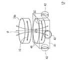
次に、図2および図3に基づき、自走ロボット4について説明する。給電装置1による給電が行われていない場合、自走ロボット4は格納ボックス21内に収容され、回動板21gは格納ボックス21に対し閉じられている。自走ロボット4は、上面視が略正方形を呈した箱型のロボットハウジング41と、ロボットハウジング41の4つの側面41aにそれぞれ回転可能に取り付けられた走行ホイール42を備えており、車両7の下方に進入可能なように薄型に形成されている(図2示)。ロボットハウジング41内には、前述したコントロールケーブル27が引き込まれている。 Next, the self-running
各々の走行ホイール42は、水平方向のいずれの向きにも移動可能な全方向車輪であり、これに限定されるべきものではないが、例えばオムニホイールが適用可能である。尚、自走ロボット4は、ロボットハウジング41を上面視が三角形状の箱体とし、それぞれの側面に走行ホイール42(合計3個)を取り付けた構成としてもよい。 Each traveling
ロボットハウジング41内には4つの直流モータ43が設けられ、それぞれ図示しない減速機を介して走行ホイール42に連結されている。それぞれの直流モータ43は、コントロールケーブル27により上述した直流モータドライバ26dに接続されている(図3示)。直流モータドライバ26dは、制御部23からの信号に基づいて各々の直流モータ43に電力を供給し、それぞれの走行ホイール42を独立して駆動する。これにより、自走ロボット4を、あらゆる方向に所定距離だけ移動させることができる。尚、走行ホイール42、直流モータ43および減速機を包括した構成は、走行駆動部に該当する。 Four
また、図2に示したように、ロボットハウジング41の上部の4隅にはそれぞれ距離センサ44が取り付けられている。距離センサ44は赤外線距離センサであって、コントロールケーブル27により固定装置2の制御部23に接続されるとともに、固定装置2から電力が供給される。それぞれの距離センサ44は、制御部23からの信号に基づいて赤外線(図4においてELにて示す)を発する発光部44aと、車両7の対応する車輪71F、71R(タイヤ)に到達した後、反射した赤外線(図4においてRLにて示す)を受光する受光部44bとを備えている。各々の距離センサ44は、各車輪71F、71Rからの距離を検出し、後述する車両7の受電部74に対する自走ロボット4の位置を検出している。 As shown in FIG. 2,
また、ロボットハウジング41のハウジング上面41bには、位置センサ受光体45(受光体に該当する)が形成されている。図2に示したように、位置センサ受光体45はハウジング上面41bの略中央部に形成されている。位置センサ受光体45は、車両7の受電部74に設けられた位置センサ発光体74a(光源に該当する)からのレーザ光を受光し、受電部74に対する自走ロボット4の位置を検出し、双方の位置合わせを行う。位置センサ受光体45は、コントロールケーブル27の信号線により、固定装置2の制御部23へ送信可能に形成されている。位置センサ発光体74aおよび位置センサ受光体45は、フォトセンサ等を利用したものであってもよい。尚、距離センサ44、位置センサ受光体45および位置センサ発光体74aを包括した構成は、給電体位置検出部に該当する。 A position sensor light receiver 45 (corresponding to a light receiver) is formed on the housing
なお、本実施形態においては、外乱光の影響を比較的受けにくい車両7の下面と地面LDとの間の隙間で自走ロボット4が移動するため、距離センサ44、位置センサ受光体45、位置センサ発光体74aはいずれも安価な受発光素子を用いているが、超音波発信機と超音波センサとを用いて、各車輪71F、71Rからの距離を検出する距離センサおよび受電部74に対する自走ロボット4の位置を検出する位置センサを構成してもよく、また撮像素子(カメラ)を用いて当該距離センサおよび位置センサを構成してもよい。 In the present embodiment, since the self-running
さらに、ロボットハウジング41内には、給電コイル46(電力供給部に該当する)が形成されている(図6示)。給電コイル46は、コントロールケーブル27により、前述した固定装置2のコイルドライバ26eと接続されており、制御部23からの信号によりコイルドライバ26eから電力が供給されて、所定周波数の交流電流が発生する。給電コイル46は、自走ロボット4の軽量化のために、アルミニウム合金による線材を使用してもよい。給電コイル46は給電時に車両7の下面と対向するように、その軸心は上下方向に向いており、ロボットハウジング41内に収容可能なように、その軸方向寸法は短く形成されている(図6示)。 Further, a feeding coil 46 (corresponding to a power supply unit) is formed in the robot housing 41 (shown in FIG. 6). The
次に、図2に基づき、車両7における本発明に関係する構成について説明する。前述した発信部72および受信部73には、車両制御部75が接続されている。車両制御部75は、CPU、記憶部および入出力部等により形成され、車両7の漏電絶縁性の確認を行っている。車両制御部75に接続された表示部76は、車両7の図示しないインスツルメントパネル等に設けられており、後述するバッテリ78の充電状態、固定装置2による車両7のID認証結果、車両7の漏電絶縁性確認結果等を表示する。 Next, a configuration related to the present invention in the
車両制御部75には、電源回路である駆動部77を介して前述した位置センサ発光体74aが接続されている。駆動部77は車両制御部75からの信号に基づいて、車両7の図示しない低圧バッテリからの電力により位置センサ発光体74aを駆動している。尚、位置センサ発光体74aに対し、低圧バッテリに代えて後述するバッテリ78から電力を供給するように構成してもよい。電力が供給された位置センサ発光体74aは、前述した位置センサ受光体45が車両7の下方において受光可能なように、車両7の略中央部から下方に向けてレーザ光を発生させるように形成されている。 The position
位置センサ発光体74aは、光源として車両7の下面に沿って延びるとともに互いに交差する一対の直線74a1、74a2(以下、第1直線74a1、第2直線74a2という)を有し、交点74a3において互いに直交し十字形状を呈している(図5示)。但し、第1直線74a1と第2直線74a2とは、必ずしも直交していなければならないわけではなく、90°以外の角度で交差していてもよい。後述するように、給電時においては自走ロボット4の給電コイル46と車両7の受電コイル74bとの軸心同士を一致させた状態で対向させるため、位置センサ発光体74aの交点74a3は、後述する受電コイル74bの軸心に位置するように形成されている。 The position
なお、車両によっては、車両7の平面視において車両7の中央部に受電コイル74bの軸心、言い換えれば交点74a3を配置できない場合もあり、受電コイル74bの軸心をたとえば(右または左)前輪71Fにより近く配置してもよく、あるいは(右または左)後輪71Rにより近く配置してもよく、さらには、前輪71F同士の中間または後輪71R同士の中間に配置していてもよい。 Depending on the vehicle, the axis of the
バッテリ78は、リチウムイオン電池等により形成された高圧バッテリであり、車両7の車輪71F、71Rを駆動するモータジェネレータ(図示せず)に電力を供給する。バッテリ78には図示しない電流センサおよび電圧センサが設けられ、これらのセンサは車両制御部75に接続されている。車両制御部75は、電流センサおよび電圧センサからの検出値に基づき、常時、バッテリ78の充電状態(バッテリ残量SOC)を監視している。 The
バッテリ78にはAC−DCコンバータ79が接続されており、AC−DCコンバータ79には、車両7の下面に形成された受電部74に含まれる受電コイル74bが接続されている。受電コイル74bは、上方から見た場合の車両7の略中央部に位置しており、その軸心方向は車両7の上下方向に向いている(図6示)。受電コイル74bは、車両7の軽量化のために、アルミニウム合金による線材を使用してもよい。受電コイル74bは、給電時に自走ロボット4の給電コイル46と対向し、給電コイル46における通電電流の変化によって誘導電流が発生する。受電コイル74bに発生した電流は、車両制御部75が制御するAC−DCコンバータ79により直流に変換された後、バッテリ78に充電される。 An AC-
次に、給電装置1による、車両7の受電部74に対する給電方法について説明する。車両7の発信部72からは、常時、車両ID信号が発せられている。バッテリ78に充電するために車両7を給電装置1に接近させると、制御部23のID認証部23aは、固定装置2の信号入力部24から入力された車両ID信号が、給電を許可された車両7のものであるか否かを判定する。車両7から出力された車両ID信号が給電を許可された車両のものである場合、制御部23は固定装置2および自走ロボット4をスタンバイさせるとともに、車両ID信号から車両7のバッテリ78の現在の充電状態を認識する。車両7から出力された車両ID信号が給電を許可された車両のものではない場合、給電装置1は車両7への給電を行わない。 Next, a power feeding method for the
車両7が給電を許可された車両である場合に、車両7の車輪71F、71RがホイールストッパSTに接近(または当接)した状態になると、停車センサ6により車両7が給電可能な位置に停車したことが検出される。これにより、制御装置23は情報送信部25から車両7の受信部73に向けて、受電部74への給電を開始することを通知する給電開始信号を送信する。給電開始信号を受信すると、車両7の車両制御部75は、表示部76に給電の開始を知らせる表示を行うとともに、駆動部77を作動させて位置センサ発光体74aからレーザ光を発生させる。また、車両制御部75はAC/DCコンバータ79をスタンバイさせ、受電コイル74bによって発生された電力をバッテリ78に充電可能な状態にする。 When the
車両7の停車を検出した固定装置2の制御部23は、開閉モータ29を作動させて回動板21gを開放するとともに、直流モータ43を駆動し自走ロボット4を格納ボックス21外に移動させる。自走ロボット4が地面LD上を移動して、格納ボックス21から車両7の下方(車両7のフロアと地面LDとの間)に進入すると、図4に示すように、自走ロボット4の各々の距離センサ44は、対向した各車輪71F、71Rに対する距離を検出する。 The
制御部23の回転数演算部23bは、それぞれの距離センサ44による検出距離に基づき、自走ロボット4の移動方向を決め、各直流モータ43の回転数(回転速度)を演算する。各々の直流モータ43は、直流モータドライバ26dによって所定速度で駆動され、自走ロボット4を車輪71F、71Rによって囲まれた車両7の略中央部に移動させる。 The rotation
距離センサ44による検出値に基づき、自走ロボット4が車両7の受電コイル74bから定められた範囲内に移動したと判断すると、制御部23は、距離センサ44に代えて(あるいは距離センサ44とともに)、位置センサ受光体45の検出値に基づいて、受電コイル74bに対して給電可能な位置に自走ロボット4を移動させる。具体的には以下のようにして、給電コイル46と受電コイル74bとの位置合わせを行うことができるが、この方法に限られるものではない。 When it is determined that the self-propelled
最初に図5(a)に示すように、自走ロボット4の移動によって、車両7側の位置センサ発光体74aを構成する第1直線74a1に向けて位置センサ受光体45が接近する。位置センサ受光体45が第1直線74a1からのレーザ光を受光すると、これまでの進行方向に対し直角方向に進行方向を変えて往復移動VL1を開始する(図5(b)示)。位置センサ受光体45の往復移動VL1により、第1直線74a1からのレーザ光を受光できなくなった場合(往復移動VL1の方向と第1直線74a1の延びる方向とが異なっている場合)、その進行方向の角度を変化させて往復移動VL2を繰り返す(図5(c)示)。 First, as shown in FIG. 5A, the position
往復移動の方向と第1直線74a1の延びる方向とが一致した場合、第1直線74a1から所定距離dだけ離れた位置において、位置センサ受光体45を第1直線74a1の延びる方向に移動させる(図5(d)示)。その後、位置センサ受光体45が第2直線74a2からのレーザ光を受光すると、現在の進行方向に対し直角方向に、その位置からdだけはなれた地点が第1直線74a1と第2直線74a2との交点74a3であることがわかる。したがって、交点74a3に向けて位置センサ受光体45を移動させ、受電コイル74bに対する給電コイル46の位置合わせが完了する(図5(e)示)。 When the reciprocating direction and the extending direction of the first straight line 74a1 coincide with each other, the
ここで、図5(d)に示した状態において、位置センサ受光体45が第1直線74a1の延びる方向であって、第2直線74a2から離れる方向(図5(d)において下方)に移動したため、所定距離移動しても第2直線74a2からの受光を検出できない場合、逆方向に向きを変えて移動することにより、第2直線74a2に到達することができる。これまで説明してきたように、距離センサ44および位置センサ受光体45の検出値によって、自走ロボット4が格納ボックス21から受電コイル74bの下方に到達するまでにたどった経路(往路)は、制御部23において記憶されている。 Here, in the state shown in FIG. 5D, the
図6に示すように、車両7の受電コイル74bと自走ロボット4の給電コイル46との位置合わせが完了し、受電コイル74bが給電コイル46に対し軸方向に対向すると、制御部23は受電部74への給電を開始する。受電部74への給電は、コイルドライバ26eにより給電コイル46に対して所定周波数の交流電流SCを印加することにより行われる。給電コイル46においては、加えられた交流電流SCにより磁束φが変化するため、受電コイル74bにおいて同じ周波数の誘導電流ICが誘起される。受電コイル74bにおいて発生した誘導電流ICは、AC/DCコンバータ79において直流電流に変換されバッテリ78に充電される。 As shown in FIG. 6, when the positioning of the
バッテリ78における充電状態は、車両7の表示部76において表示されるとともに、充電状態信号が発信部72を介して固定装置2に送信され、家屋内においても表示される。さらに、充電状態信号は固定装置2から携帯電話PSにも送信され、現在の充電状態が携帯電話PSの使用者にも知らされる。 The state of charge in the
バッテリ78が満充電状態となると、車両7から固定装置2に対して充電完了信号が送信されるため、制御部23は給電コイル46への通電を停止した後、自走ロボット4を再び格納ボックス21に収容し、回動板21gを格納ボックス21に対して閉止状態とする。自走ロボット4を格納ボック21内に戻す場合、制御部23に記憶されている自走ロボット4の往路の経路を逆方向にたどるようにして移動させる。また、自走ロボット4が格納ボックス21に戻る場合、リールモータ26aを駆動して、リールシャフト26cによりコントロールケーブル27を巻き取りながら移動させる。 When the
本実施形態によれば、格納ボックス21内に収容されるとともに電源に接続され、地面LD上を移動して格納ボックス21外に出た後、停車された車両7と地面LDとの間に進入し、電源からの電力を用いて、車両7の下面に形成された受電部74に給電する自走ロボット4と、受電部74に対する自走ロボット4の位置を検出する距離センサ44または位置センサ受光体45と、車両7から発信された車両7の車両ID信号を受信する信号入力部24と、距離センサ44または位置センサ受光体45の検出値および信号入力部24が受信した車両ID信号に基づき、自走ロボット4の作動を制御する制御部23とを備えたことにより、車両7と地面LDとの間に進入可能な薄型の自走ロボット4を収容する僅かな設置スペースを地面LD上に設けるのみで給電装置1を形成することができる。したがって、家庭に設けるか公共施設に設けるかといった設置場所の制約を受けることなく、既存設備の大幅な改造を必要とせずに給電装置1を設置することが可能となる。 According to this embodiment, after being accommodated in the
また、普段、自走ロボット4は格納ボックス21内に収容されているため、車両7の洗車時、ドア開閉時、後方ハッチバックドア開閉時等に邪魔になることがない。
また、車両7への給電を自走ロボット4が自動的に行なうため、面倒な充電作業を車両7の使用者が行う必要がない。そのため、充電作業にともなう身体の汚れを防止でき、高電圧に対する危険を防ぐことができる。Moreover, since the self-propelled
Further, since the self-propelled
また、格納ボックス21は車両7の停車時における車輪71F、71Rの位置を規制する一対のホイールストッパST間に配置されることにより、車両7を駐車場に停車すれば格納ボックス21が車両7の下方に入り込むため、自走ロボット4に雨水等がかからない状態で車両7への給電を行うことができる。
また、格納ボックス21と停車時の車輪71F、71Rとの間を遮るように、パーキングプロテクタ5が地面LD上に取り付けられたことにより、車両7を駐車場に停車する際に、誤って車輪71F、71Rが固定装置2を踏みつぶすことを防止することができる。Further, the
Further, when the parking protector 5 is mounted on the ground LD so as to block between the
また、受電部74に形成された光源としての位置センサ発光体74aと、位置センサ発光体74aからの光を受ける位置センサ受光体45とを備え、位置センサ発光体74aは、互いに交差する一対の第1直線74a1と第2直線74a2とにより形成されていることにより、位置センサ受光体45を第1直線74a1と第2直線74a2との交点74a3まで容易に移動させることができるため、短時間で受電部74と自走ロボット4との位置合わせをすることができる。 The
また、自走ロボット4の車輪71F、71Rからの距離を検出する距離センサ44を備え、距離センサ44の検出値に基づき、自走ロボット4を受電コイル74bから定められた範囲内に移動させた後、位置センサ受光体45の検出値に基づいて、受電部74に対して給電可能な位置に自走ロボット4を移動させることにより、車両7と地面LDとの間に進入した自走ロボット4を、最初に距離センサ44を用いて受電部74の近くまで迅速に移動させ、その後、位置センサ受光体45の検出値に基づいて、受電部74に対して正確に位置合わせすることができる。 Moreover, the
<実施形態2>
以下、図7に基づき、本発明の実施形態2による給電装置1について説明する。本実施形態による給電コイル46は、合成樹脂材料により形成された給電側インシュレータ46aに巻回されている。給電側インシュレータ46aの内孔46a1には、給電側コア46bが軸方向(図7において上下方向)に移動可能に挿入されている。また、給電側インシュレータ46aには、内孔46a1に対して直交するように、複数のプランジャ孔46a2が形成されている。<
Hereinafter, based on FIG. 7, the
また、給電側コア46bの外周面には、プランジャ孔46a2と対向して円周上を取り巻くように凹部46b1が形成されている。図7に示すように凹部46b1には、図7において下方に行くにつれて深くなる複数のノッチ段差46b2が形成され、各々のノッチ段差46b2の間には段差壁46b3が形成されている。さらに、図7において凹部46b1の上端部には端部壁46b4が形成されており、端部壁46b4は段差壁46b3よりも高く形成されている。 In addition, a recess 46b1 is formed on the outer peripheral surface of the power
上述した各々のプランジャ孔46a2内には、保持ピストン46cが軸方向に移動可能に設けられている。また、保持ピストン46cとプランジャ孔46a2の底部との間には、保持ピストン46cを給電側コア46bに向けて付勢するピストンバネ46dが配置されている。ピストンバネ46dの付勢力により保持ピストン46cは、常時、ノッチ段差46b2のいずれかと係合しており、端部壁46b4を乗り越えることは不能に形成されている。 In each plunger hole 46a2, the
また、図7に示したように、保持ピストン46cの先端は半球状に形成されており、給電コイル46によって給電側コア46bに所定の電磁力が発生した場合、給電側コア46bの軸方向上方への移動は許容されるが、下方への移動を防止するように形成されている。しかしながら、給電側コア46bに所定値よりもさらに大きい電磁力が発生した場合、ピストンバネ46dを撓ませることにより、保持ピストン46cが段差壁46b3を乗り越え、給電側コア46bの軸方向下方への移動も許容されるように形成されている。 Further, as shown in FIG. 7, the tip of the
一方、受電コイル74bは、合成樹脂材料により形成された受電側インシュレータ74cに巻回されている。受電側インシュレータ74cの内孔74c1には、受電側コア74dが挿入された状態で固定されている。尚、本実施形態においては、位置センサ受光体45および位置センサ発光体74aを、それぞれ給電コイル46または受電コイル74bの軸心上以外の位置に配置する必要がある。 On the other hand, the
次に、本実施形態の給電装置1による給電方法について説明する。図7(a)に示したように、給電を開始する前に、給電コイル46の軸方向上端部と受電コイル74bの軸方向下端部とは、互いに間隔を保持して対向した状態にある。この状態において、ピストンバネ46dからの付勢力を受けた保持ピストン46cは、凹部46b1の上端にあるノッチ段差46b2と係合している。 Next, a power feeding method by the
次に、給電コイル46に直流電流を印加することにより、給電側コア46bが電磁力Fを受けて軸方向上方に移動して、受電側コア74dの下端面に当接する(図7(b)示)。この時、保持ピストン46cは、より深いノッチ段差46b2と係合することが可能であるため、給電側コア46bの上方への移動を妨げることはない。その後、給電コイル46に交流電流を供給して、受電コイル74bに誘導電流を発生させることにより受電部74に給電を行う。交流電流が給電コイル46に供給されたとき、保持ピストン46cがノッチ段差46b2と係合しているため、給電側コア46bは下降せずに保持される。 Next, by applying a direct current to the
受電部74への充電が終了すると、給電コイル46に対し、給電前とは逆方向に、給電時の交流電流よりも多くの磁束を発生させるように直流電流を印加する。これにより、給電側コア46bが軸方向下方に移動して、受電側コア74dから離れる。この時、強大な電磁力によって給電側コア46bが付勢されるため、保持ピストン46cはピストンバネ46dを撓ませて段差壁46b3を乗り越えることができる。 When charging of the
本実施形態によれば、給電時において、給電コイル46に直流電流を印加して、給電側コア46bを軸方向に移動させて受電側コア74dに当接させた後、給電コイル46に交流電流を供給して、受電コイル74bに発生させる誘導電流によって受電部74に給電することにより、特別なアクチュエータを使用しなくても給電側コア46bを受電側コア74dに当接させることができ、低周波の電流でも受電部74に十分な給電を行うことができる。 According to the present embodiment, at the time of power feeding, a direct current is applied to the
<他の実施形態>
本発明は、上述した実施形態に限定されるものではなく、次のように変形または拡張することができる。
自走ロボット4を収容する格納ボックス21を家屋の床下に形成したり、家屋の床材を用いて形成するようにしてもよい。
また、自走ロボット4を格納ボックス21に収容する場合、記憶されている自走ロボット4の往路の経路に基づいて移動させる代わりに、固定装置2に発光装置を設け、自走ロボット4が検出した当該発光装置からの光に基づいて移動させてもよい。
また、自走ロボット4を格納ボックス21に収容する場合、コントロールケーブル27をリールシャフト26cにより巻き取るのではなく、図1に示したように、伸縮自在のコントロールケーブル27にしてもよい。<Other embodiments>
The present invention is not limited to the above-described embodiments, and can be modified or expanded as follows.
You may make it form the
Further, when the self-running
When the self-propelled
また、自走ロボット4による受電部74への給電方式は、上述したように非接触方式に限られるものではなく、接触方式であってもよい。
また、給電体位置検出部として、距離センサ44のみを使用してもよいし、位置センサ受光体45および位置センサ発光体74aの組み合わせのみを使用してもよい。
また、位置センサ発光体74aを自走ロボット4側に設け、位置センサ受光体45を車両7側に設けてもよい。
また、位置センサ発光体74aを点状に形成し、位置センサ受光体45を十字形状に形成してもよい。
また、駐車場の地面LD上にホイールストッパSTを1つだけ取り付け、固定装置2を当該ホイールストッパSTに対して、車両7の幅方向位置に近接するように設けてもよい。
また、バッテリ78が満充電状態となったことを検出して給電を停止する代わりに、制御部23に形成されたタイマーによって所定時間だけ給電した後、受電部74への給電を終了するようにしてもよい。Further, the power feeding method to the
Further, only the
Further, the position
Further, the position
Further, only one wheel stopper ST may be attached on the ground LD of the parking lot, and the fixing
Instead of detecting that the
図面中、1は給電装置、4は自走ロボット(給電体)、5はパーキングプロテクタ(保護部材)、7は車両、8は交流電源(電源)、21は格納ボックス(格納部材)、23は制御部、24は信号入力部(情報受信部)、42は走行ホイール(走行駆動部)、43は直流モータ(走行駆動部)、44は距離センサ、45は位置センサ受光体(受光体、給電体位置検出部)、46は給電コイル(電力供給部)、46bは給電側コア(電力供給部)、71Fは前輪、71Rは後輪、74は受電部、74aは位置センサ発光体(光源、給電体位置検出部)、74a1は第1直線、74a2は第2直線、74bは受電コイル、74dは受電側コア、78はバッテリ、LDは地面、STはホイールストッパ(輪止め)を示している。 In the drawings, 1 is a power supply device, 4 is a self-propelled robot (power supply body), 5 is a parking protector (protective member), 7 is a vehicle, 8 is an AC power supply (power supply), 21 is a storage box (storage member), and 23 is Control unit, 24 is a signal input unit (information receiving unit), 42 is a traveling wheel (traveling drive unit), 43 is a DC motor (traveling drive unit), 44 is a distance sensor, 45 is a position sensor light receiver (light receiver, power feeding) Body position detection unit), 46 is a power supply coil (power supply unit), 46b is a power supply side core (power supply unit), 71F is a front wheel, 71R is a rear wheel, 74 is a power reception unit, 74a is a position sensor light emitter (light source, 74a1 is a first straight line, 74a2 is a second straight line, 74b is a power receiving coil, 74d is a power receiving side core, 78 is a battery, LD is the ground, and ST is a wheel stopper (ring stopper). .
Claims (6)
Translated fromJapanese該格納部材内に収容されるとともに電源に接続された給電体であって、前記地面上を移動して前記格納部材外に出た後、停車された前記車両と前記地面との間に進入するための走行駆動部と、前記車両のバッテリに充電するために、前記電源からの電力を用いて前記車両の下面に形成された受電部に給電する電力供給部とを含む前記給電体と、
前記受電部に対する前記給電体の位置を検出する給電体位置検出部と、
前記車両から発信された充電情報を受信する情報受信部と、
前記給電体位置検出部の検出値および前記情報受信部が受信した前記充電情報に基づき、前記給電体の作動を制御する制御部と、
を備えた車両給電装置。A storage member provided on the ground where the vehicle is stopped;
A power feeder housed in the storage member and connected to a power source, moves on the ground and exits the storage member, and then enters between the stopped vehicle and the ground. And a power supply unit that feeds power to a power receiving unit formed on a lower surface of the vehicle using electric power from the power source to charge a battery of the vehicle.
A power feeder position detector that detects the position of the power feeder relative to the power receiver;
An information receiving unit for receiving charging information transmitted from the vehicle;
Based on the detection value of the power feeder position detection unit and the charging information received by the information receiving unit, a control unit that controls the operation of the power feeder;
The vehicle electric power feeder provided with.
前記受電部および前記給電体の上面の内のいずれか一方に形成された光源と、他方に設けられ前記光源からの光を受ける受光体とを含み、前記光源および前記受光体のうちの一側は、互いに交差する一対の直線により形成されている請求項1乃至3のうちのいずれか一項に記載の車両給電装置。The power feeder position detector
A light source formed on one of the power receiving unit and the upper surface of the power feeding body, and a light receiving body provided on the other side for receiving light from the light source, and one side of the light source and the light receiving body Is a vehicle power feeding device according to any one of claims 1 to 3, which is formed by a pair of straight lines intersecting each other.
前記給電体に設けられ、停車時の前記車両における前記車輪からの距離を検出する距離センサを含み、
前記制御部は、
前記車両と前記地面との間に進入した前記給電体を、前記距離センサの検出値に基づき、前記受電部から定められた範囲内に移動させた後、前記受光体の検出値に基づいて、前記受電部に対して給電可能な位置に前記給電体を移動させる請求項4記載の車両給電装置。The power feeder position detector
A distance sensor that is provided in the power feeding body and detects a distance from the wheel in the vehicle when the vehicle is stopped;
The controller is
Based on the detection value of the light receiver, after moving the power feeder that has entered between the vehicle and the ground within a range determined from the power receiving unit based on the detection value of the distance sensor, The vehicle electric power feeder of Claim 4 which moves the said electric power feeding body to the position which can be electrically fed with respect to the said power receiving part.
給電時において、前記給電コイルの軸方向端部と前記受電コイルの軸方向端部とが、互いに間隔を保持して対向した状態で、前記給電コイルに直流電流が印加されることにより、前記給電側コアが軸方向に移動して前記受電側コアに当接した後、前記給電コイルに交流電流を供給して、前記受電コイルに誘導電流を発生させる請求項1乃至5のうちのいずれか一項に記載の車両給電装置。The power supply unit of the power supply body is provided with a power supply side core extending in a vertical direction and a power supply coil wound so as to surround the power supply side core, and the power supply side core is connected to the power supply coil. The power receiving unit of the vehicle is provided with a power receiving side core extending in the vertical direction and a power receiving coil wound around the power receiving side core,
At the time of feeding, a DC current is applied to the feeding coil in a state where the axial end of the feeding coil and the axial end of the receiving coil face each other with a gap therebetween, whereby the feeding 6. The method according to claim 1, wherein after the side core moves in the axial direction and contacts the power receiving side core, an alternating current is supplied to the power feeding coil to generate an induced current in the power receiving coil. The vehicle electric power feeder as described in a term.
Priority Applications (1)
| Application Number | Priority Date | Filing Date | Title |
|---|---|---|---|
| JP2012059686AJP5895631B2 (en) | 2012-03-16 | 2012-03-16 | Vehicle power supply device |
Applications Claiming Priority (1)
| Application Number | Priority Date | Filing Date | Title |
|---|---|---|---|
| JP2012059686AJP5895631B2 (en) | 2012-03-16 | 2012-03-16 | Vehicle power supply device |
Publications (2)
| Publication Number | Publication Date |
|---|---|
| JP2013198187Atrue JP2013198187A (en) | 2013-09-30 |
| JP5895631B2 JP5895631B2 (en) | 2016-03-30 |
Family
ID=49396520
Family Applications (1)
| Application Number | Title | Priority Date | Filing Date |
|---|---|---|---|
| JP2012059686AExpired - Fee RelatedJP5895631B2 (en) | 2012-03-16 | 2012-03-16 | Vehicle power supply device |
Country Status (1)
| Country | Link |
|---|---|
| JP (1) | JP5895631B2 (en) |
Cited By (17)
| Publication number | Priority date | Publication date | Assignee | Title |
|---|---|---|---|---|
| JP2017093223A (en)* | 2015-11-13 | 2017-05-25 | 株式会社東芝 | Power reception device, power transmission device, and wireless electric power transmission system |
| EP3176023A1 (en)* | 2015-12-04 | 2017-06-07 | Audi Ag | Energy supply device, energy supply system and method for supplying energy to a motor vehicle |
| JP2017137701A (en)* | 2016-02-04 | 2017-08-10 | 矢崎総業株式会社 | Car stop, coil unit and power supply system having them |
| JP2018121478A (en)* | 2017-01-26 | 2018-08-02 | 電気興業株式会社 | Wireless charging system for vehicles and wired/wireless charging system for vehicles |
| DE102017205233A1 (en)* | 2017-03-28 | 2018-10-04 | Chargery GmbH | Autonomous charging unit for an energy storage station |
| FR3066052A1 (en)* | 2017-05-03 | 2018-11-09 | Peugeot Citroen Automobiles Sa | BATTERY INDUCTION RECHARGING DEVICE (S) OF A VEHICLE WITH MULTIPLE POWER OUTLETS FOR A MOBILE HOUSING |
| WO2019037973A1 (en)* | 2017-08-22 | 2019-02-28 | Zf Friedrichshafen Ag | CHARGING VEHICLE AND METHOD FOR LOADING AN ELECTRIC VEHICLE |
| WO2019073133A1 (en)* | 2017-10-12 | 2019-04-18 | Psa Automobiles Sa | Recharge by induction of electrical vehicles by means of a robot |
| CN109969012A (en)* | 2019-04-24 | 2019-07-05 | 东北大学 | A coil position automatic correction system applied in the wireless charging process of automobiles |
| CN110040027A (en)* | 2019-04-28 | 2019-07-23 | 西安唯电电气技术有限公司 | A kind of smart charge control system and method for electric car |
| FR3084025A1 (en)* | 2018-07-19 | 2020-01-24 | Psa Automobiles Sa | AUTONOMOUS MOBILE HOUSING WITH ILLUMINATION OF ITS SURROUNDINGS, FOR INDUCILY CHARGING A VEHICLE BATTERY |
| WO2020043969A1 (en)* | 2018-08-28 | 2020-03-05 | Psa Automobiles Sa | System for detecting the position of a first movable machine with respect to a second machine, using polarised photons |
| FR3086593A1 (en) | 2018-09-28 | 2020-04-03 | Psa Automobiles Sa | INDUCTION RECHARGE DEVICE |
| FR3087056A1 (en) | 2018-10-08 | 2020-04-10 | Psa Automobiles Sa | INDUCTION RECHARGE DEVICE |
| WO2023161593A1 (en)* | 2022-02-28 | 2023-08-31 | Electricfil Automotive | Charging robot for an electric motor vehicle guided by its unwound electric cable and operating method thereof |
| JP2024090964A (en)* | 2022-12-23 | 2024-07-04 | トヨタ自動車株式会社 | Charging equipment |
| KR20250091798A (en)* | 2023-12-14 | 2025-06-23 | 주식회사 유에이로보틱스 | Folding type battery cart and unmanned charging system for electric vehicle including the same |
Families Citing this family (3)
| Publication number | Priority date | Publication date | Assignee | Title |
|---|---|---|---|---|
| DE102018204820A1 (en)* | 2018-03-29 | 2019-10-02 | Ford Global Technologies, Llc | Loading robot and method for its operation |
| CN111391681B (en)* | 2020-06-05 | 2020-08-28 | 深圳赫兹创新技术有限公司 | Charging system and charging management platform of portable wireless transmitting terminal that charges |
| FR3142131A1 (en)* | 2022-11-17 | 2024-05-24 | Psa Automobiles Sa | DEVICE COMPRISING A PROTECTIVE STRUCTURE CARRIER OF AN ELECTRIC CHARGING MEANS FOR ELECTRIC VEHICLE |
Citations (14)
| Publication number | Priority date | Publication date | Assignee | Title |
|---|---|---|---|---|
| JPS58142208A (en)* | 1982-02-19 | 1983-08-24 | Hitachi Ltd | Position detection method and device |
| JPH089512A (en)* | 1994-06-23 | 1996-01-12 | Toyota Autom Loom Works Ltd | Electromagnetic power supply for motor-driven vehicle |
| JPH0917666A (en)* | 1995-06-28 | 1997-01-17 | Toyota Autom Loom Works Ltd | Positioning method for charging device and its positioning device |
| JPH09215211A (en)* | 1996-02-02 | 1997-08-15 | Sumitomo Wiring Syst Ltd | Electric vehicle charging system |
| JPH10322921A (en)* | 1997-05-15 | 1998-12-04 | Sumitomo Wiring Syst Ltd | Magnetic coupling device for electric vehicle charging |
| JP2002345104A (en)* | 2001-05-16 | 2002-11-29 | Tsubakimoto Chain Co | Non-contact power feeding system |
| JP2006288034A (en)* | 2005-03-31 | 2006-10-19 | Matsushita Electric Ind Co Ltd | Power transmission / reception device |
| JP2006345588A (en)* | 2005-06-07 | 2006-12-21 | Matsushita Electric Works Ltd | Noncontact power supply and power supply system for autonomous mobile unit |
| JP2011091882A (en)* | 2009-10-20 | 2011-05-06 | Suri-Ai:Kk | Induction type vehicle power feed device |
| JP2011097671A (en)* | 2009-10-27 | 2011-05-12 | Nippon Tekumo:Kk | Non-contact power supply device |
| JP2011167009A (en)* | 2010-02-12 | 2011-08-25 | Nippon Tekumo:Kk | Noncontact power supply |
| US20110204845A1 (en)* | 2010-02-25 | 2011-08-25 | Evatran Llc | System and method for inductively transferring ac power and self alignment between a vehicle and a recharging station |
| WO2011125632A1 (en)* | 2010-03-31 | 2011-10-13 | 本田技研工業株式会社 | Contactless charging system |
| JP2011254593A (en)* | 2010-05-31 | 2011-12-15 | Toyota Motor Corp | Charger |
- 2012
- 2012-03-16JPJP2012059686Apatent/JP5895631B2/ennot_activeExpired - Fee Related
Patent Citations (14)
| Publication number | Priority date | Publication date | Assignee | Title |
|---|---|---|---|---|
| JPS58142208A (en)* | 1982-02-19 | 1983-08-24 | Hitachi Ltd | Position detection method and device |
| JPH089512A (en)* | 1994-06-23 | 1996-01-12 | Toyota Autom Loom Works Ltd | Electromagnetic power supply for motor-driven vehicle |
| JPH0917666A (en)* | 1995-06-28 | 1997-01-17 | Toyota Autom Loom Works Ltd | Positioning method for charging device and its positioning device |
| JPH09215211A (en)* | 1996-02-02 | 1997-08-15 | Sumitomo Wiring Syst Ltd | Electric vehicle charging system |
| JPH10322921A (en)* | 1997-05-15 | 1998-12-04 | Sumitomo Wiring Syst Ltd | Magnetic coupling device for electric vehicle charging |
| JP2002345104A (en)* | 2001-05-16 | 2002-11-29 | Tsubakimoto Chain Co | Non-contact power feeding system |
| JP2006288034A (en)* | 2005-03-31 | 2006-10-19 | Matsushita Electric Ind Co Ltd | Power transmission / reception device |
| JP2006345588A (en)* | 2005-06-07 | 2006-12-21 | Matsushita Electric Works Ltd | Noncontact power supply and power supply system for autonomous mobile unit |
| JP2011091882A (en)* | 2009-10-20 | 2011-05-06 | Suri-Ai:Kk | Induction type vehicle power feed device |
| JP2011097671A (en)* | 2009-10-27 | 2011-05-12 | Nippon Tekumo:Kk | Non-contact power supply device |
| JP2011167009A (en)* | 2010-02-12 | 2011-08-25 | Nippon Tekumo:Kk | Noncontact power supply |
| US20110204845A1 (en)* | 2010-02-25 | 2011-08-25 | Evatran Llc | System and method for inductively transferring ac power and self alignment between a vehicle and a recharging station |
| WO2011125632A1 (en)* | 2010-03-31 | 2011-10-13 | 本田技研工業株式会社 | Contactless charging system |
| JP2011254593A (en)* | 2010-05-31 | 2011-12-15 | Toyota Motor Corp | Charger |
Cited By (23)
| Publication number | Priority date | Publication date | Assignee | Title |
|---|---|---|---|---|
| JP2017093223A (en)* | 2015-11-13 | 2017-05-25 | 株式会社東芝 | Power reception device, power transmission device, and wireless electric power transmission system |
| EP3176023A1 (en)* | 2015-12-04 | 2017-06-07 | Audi Ag | Energy supply device, energy supply system and method for supplying energy to a motor vehicle |
| DE102015015698A1 (en)* | 2015-12-04 | 2017-06-08 | Audi Ag | Energy supply and energy supply system for supplying energy to a motor vehicle |
| JP2017137701A (en)* | 2016-02-04 | 2017-08-10 | 矢崎総業株式会社 | Car stop, coil unit and power supply system having them |
| JP2018121478A (en)* | 2017-01-26 | 2018-08-02 | 電気興業株式会社 | Wireless charging system for vehicles and wired/wireless charging system for vehicles |
| DE102017205233A1 (en)* | 2017-03-28 | 2018-10-04 | Chargery GmbH | Autonomous charging unit for an energy storage station |
| FR3066052A1 (en)* | 2017-05-03 | 2018-11-09 | Peugeot Citroen Automobiles Sa | BATTERY INDUCTION RECHARGING DEVICE (S) OF A VEHICLE WITH MULTIPLE POWER OUTLETS FOR A MOBILE HOUSING |
| WO2019037973A1 (en)* | 2017-08-22 | 2019-02-28 | Zf Friedrichshafen Ag | CHARGING VEHICLE AND METHOD FOR LOADING AN ELECTRIC VEHICLE |
| CN111051120A (en)* | 2017-08-22 | 2020-04-21 | Zf 腓德烈斯哈芬股份公司 | Charging vehicle and method of charging electric vehicle |
| WO2019073133A1 (en)* | 2017-10-12 | 2019-04-18 | Psa Automobiles Sa | Recharge by induction of electrical vehicles by means of a robot |
| FR3072339A1 (en)* | 2017-10-12 | 2019-04-19 | Psa Automobiles Sa | INDUCTION RECHARGE OF ELECTRIC VEHICLE USING A ROBOT |
| FR3084025A1 (en)* | 2018-07-19 | 2020-01-24 | Psa Automobiles Sa | AUTONOMOUS MOBILE HOUSING WITH ILLUMINATION OF ITS SURROUNDINGS, FOR INDUCILY CHARGING A VEHICLE BATTERY |
| FR3085314A1 (en)* | 2018-08-28 | 2020-03-06 | Psa Automobiles Sa | SYSTEM FOR DETECTING THE POSITION OF A FIRST MOBILE MACHINE IN RELATION TO A SECOND MACHINE, BY POLARIZED PHOTONS |
| WO2020043969A1 (en)* | 2018-08-28 | 2020-03-05 | Psa Automobiles Sa | System for detecting the position of a first movable machine with respect to a second machine, using polarised photons |
| FR3086593A1 (en) | 2018-09-28 | 2020-04-03 | Psa Automobiles Sa | INDUCTION RECHARGE DEVICE |
| FR3087056A1 (en) | 2018-10-08 | 2020-04-10 | Psa Automobiles Sa | INDUCTION RECHARGE DEVICE |
| CN109969012A (en)* | 2019-04-24 | 2019-07-05 | 东北大学 | A coil position automatic correction system applied in the wireless charging process of automobiles |
| CN110040027A (en)* | 2019-04-28 | 2019-07-23 | 西安唯电电气技术有限公司 | A kind of smart charge control system and method for electric car |
| WO2023161593A1 (en)* | 2022-02-28 | 2023-08-31 | Electricfil Automotive | Charging robot for an electric motor vehicle guided by its unwound electric cable and operating method thereof |
| FR3133031A1 (en)* | 2022-02-28 | 2023-09-01 | Electricfil Automotive | Loader robot for electric motor vehicle, guided via its unwound electric cable and its method of operation |
| JP2024090964A (en)* | 2022-12-23 | 2024-07-04 | トヨタ自動車株式会社 | Charging equipment |
| KR20250091798A (en)* | 2023-12-14 | 2025-06-23 | 주식회사 유에이로보틱스 | Folding type battery cart and unmanned charging system for electric vehicle including the same |
| KR102852765B1 (en)* | 2023-12-14 | 2025-09-01 | 주식회사 유에이로보틱스 | Folding type battery cart and unmanned charging system for electric vehicle including the same |
Also Published As
| Publication number | Publication date |
|---|---|
| JP5895631B2 (en) | 2016-03-30 |
Similar Documents
| Publication | Publication Date | Title |
|---|---|---|
| JP5895631B2 (en) | Vehicle power supply device | |
| US10576833B2 (en) | Vehicle charger positioning method and charger assembly | |
| US8933663B2 (en) | Method for charging a traction battery, device for transmitting energy to an electric vehicle and electric vehicle | |
| KR101386432B1 (en) | Vehicle Inductive Charging System with Electronic Positioning Aid | |
| US20210001737A1 (en) | Plug-In System for Charging an Electrical Energy Store | |
| JP5606098B2 (en) | Mobile power supply system | |
| US10668829B2 (en) | Passive flux bridge for charging electric vehicles | |
| JP5900636B2 (en) | Mobile system | |
| JP6024106B2 (en) | Transfer device and mobile vehicle | |
| WO2010090333A1 (en) | Power supply system for moving body, and moving body | |
| JP5950028B2 (en) | Contactless power supply system | |
| US20140091757A1 (en) | Charging Device and Charging Method with Float-Mounted Charging Unit | |
| WO2014027506A1 (en) | Moving parking facility | |
| CN104335450A (en) | Vehicle capable of contact-free power reception | |
| JP5577128B2 (en) | Contactless charging system | |
| EP2632762A1 (en) | Wireless energy transfer via coupled parasitic resonators | |
| KR20120038317A (en) | Contactless power transfer apparatus, inductive power supply apparatus and inductive power collection apparatus and moving object using the same | |
| WO2014017281A1 (en) | Contactless power-supply system | |
| JP2014112063A (en) | Non-contact power supply device | |
| JP2016010382A (en) | Self-propelled mower | |
| KR102033326B1 (en) | Electric carts for charging electric vehicles that run on basis of user driving control and autonomous driving ensuring driving safety by central control and adiministrator control | |
| CN110481346A (en) | A kind of hybrid power supply unmanned truck system | |
| JP2016226073A (en) | Wireless power transmission system | |
| JP6145934B2 (en) | Contactless power feeding device and contactless power receiving device | |
| JP2016211210A (en) | Parking facility system |
Legal Events
| Date | Code | Title | Description |
|---|---|---|---|
| A621 | Written request for application examination | Free format text:JAPANESE INTERMEDIATE CODE: A621 Effective date:20150210 | |
| A977 | Report on retrieval | Free format text:JAPANESE INTERMEDIATE CODE: A971007 Effective date:20151029 | |
| A131 | Notification of reasons for refusal | Free format text:JAPANESE INTERMEDIATE CODE: A131 Effective date:20151117 | |
| A521 | Written amendment | Free format text:JAPANESE INTERMEDIATE CODE: A523 Effective date:20160115 | |
| TRDD | Decision of grant or rejection written | ||
| A01 | Written decision to grant a patent or to grant a registration (utility model) | Free format text:JAPANESE INTERMEDIATE CODE: A01 Effective date:20160202 | |
| A61 | First payment of annual fees (during grant procedure) | Free format text:JAPANESE INTERMEDIATE CODE: A61 Effective date:20160215 | |
| R151 | Written notification of patent or utility model registration | Ref document number:5895631 Country of ref document:JP Free format text:JAPANESE INTERMEDIATE CODE: R151 | |
| LAPS | Cancellation because of no payment of annual fees |