JP2013196629A - Information processing apparatus and its control method, and computer program and computer-readable medium - Google Patents
Information processing apparatus and its control method, and computer program and computer-readable mediumDownload PDFInfo
- Publication number
- JP2013196629A JP2013196629AJP2012066094AJP2012066094AJP2013196629AJP 2013196629 AJP2013196629 AJP 2013196629AJP 2012066094 AJP2012066094 AJP 2012066094AJP 2012066094 AJP2012066094 AJP 2012066094AJP 2013196629 AJP2013196629 AJP 2013196629A
- Authority
- JP
- Japan
- Prior art keywords
- inspection
- information
- value
- processing apparatus
- information processing
- Prior art date
- Legal status (The legal status is an assumption and is not a legal conclusion. Google has not performed a legal analysis and makes no representation as to the accuracy of the status listed.)
- Pending
Links
Images


Landscapes
- Management, Administration, Business Operations System, And Electronic Commerce (AREA)
- Medical Treatment And Welfare Office Work (AREA)
- Investigating Or Analysing Biological Materials (AREA)
- Measuring And Recording Apparatus For Diagnosis (AREA)
Abstract
Description
Translated fromJapanese本発明は血糖計等に代表される生体情報を測定する医療機器の点検管理技術に関するものである。 The present invention relates to an inspection management technique for medical equipment that measures biological information represented by a blood glucose meter or the like.
生体情報を頻繁に測定する医療機器に血糖計,電子血圧計がある。血糖計の場合、測定方法にも幾つかの手法があるが、血液をサンプリングし、血液が浸透するフィルタに、光をあて、その反射光から血糖値を測定するものである(特許文献1)。 Blood glucose meters and electronic blood pressure monitors are medical devices that frequently measure biological information. In the case of a blood glucose meter, there are several methods for measuring, but blood is sampled, light is applied to a filter through which blood penetrates, and the blood glucose level is measured from the reflected light (Patent Document 1). .
かかる血糖計の場合、測定結果の信憑性(又は信頼度)を担保するため、一般には、QC(Quality Control)点検を例えば所定期間(例えば1ケ月)を周期で行う。QC点検では、既知の血糖値を持つサンプルを実測し、その測定結果とサンプルとの差が許容範囲内にあるかどうかを検査し、許容範囲内にある場合には、その使用を継続する。そして、許容範囲を超える測定結果が得られた場合には、メーカに修理もしくは部品交換等の依頼(以下、部品交換を含め単に「修理」とする)することになる。 In the case of such a blood glucose meter, in order to ensure the credibility (or reliability) of the measurement result, in general, QC (Quality Control) inspection is performed periodically, for example, for a predetermined period (for example, one month). In the QC check, a sample having a known blood glucose level is actually measured, whether or not the difference between the measurement result and the sample is within the allowable range is checked, and if it is within the allowable range, the use is continued. If a measurement result that exceeds the allowable range is obtained, the manufacturer is requested to repair or replace parts (hereinafter simply referred to as “repair” including parts replacement).
また、電子血圧計の場合、病院内などで医療従事者が手動加圧方式の血圧計を使用する場合に、血圧計本体部と送気球を片手で持って操作するので、使用している間に血圧計本体部に振動を与えたり、血圧計本体部と送気球を落下させてしまうと、調整済みの半固定抵抗器が動いて調整値にずれを発生させてしまうので定期的に圧力センサの調整が必要になる。 In the case of an electronic sphygmomanometer, when a medical worker uses a manually pressurized sphygmomanometer in a hospital or the like, the sphygmomanometer body and the air balloon are operated with one hand. If the sphygmomanometer body is vibrated or the sphygmomanometer body and the air balloon are dropped, the adjusted semi-fixed resistor will move and cause a deviation in the adjustment value. Adjustment is required.
上記の通りであるので、QC点検にて許容範囲を超えるような値が測定されると修理の手続を行うことになる。当然、修理を行うためには、代替となる他の血糖計(代替血糖計)を確保されていることが必要になる。そのためには、十分な数の血糖計を予め用意しておくことであるが、これではコストの面で問題がある。 As described above, if a value exceeding the allowable range is measured in the QC inspection, a repair procedure is performed. Of course, in order to perform repair, it is necessary to secure another blood glucose meter (alternative blood glucose meter) as an alternative. For this purpose, a sufficient number of blood glucose meters must be prepared in advance, but this is problematic in terms of cost.
本発明は上記問題点に鑑みなされたものであって、点検での検査結果を蓄積し、将来の修理時期を予測し報知することで、無駄の少ない、部品交換や修理依頼を事前に計画立てることを可能ならしめる技術を提供しようとするものである。 The present invention has been made in view of the above problems, and accumulates inspection results in inspection, predicts and notifies future repair timing, and plans parts replacement and repair requests with little waste in advance. We intend to provide technology that makes things possible.
係る課題を解決するため、本発明の情報処理装置は以下の構成を備える。すなわち、
患者の生体情報を測定する医療機器の点検履歴を管理する情報処理装置であって、
医療機器の点検実施日、並びに点検の際に用いた既知の生体情報値を持つサンプルに対して当該医療機器で実測して得た実測値とで構成される点検履歴情報を記憶する記憶手段と、
前記記憶手段を参照して、過去の各点検の実施日と前記既知の生体値に対するそれぞれの実測値との差分値で表わされる「実施日,差分値」のペアを、時間軸、差分値軸とする座標空間における点と見なし、当該点の集合に対して近似する線分を表わす近似関数を導出する導出手段と、
予め設定された許容差分値が定義された前記座標空間に対し、前記導出手段で導出した近似関数が示す線分をプロットした画像をグラフとして表示すると共に、前記近似関数が示す線分と前記許容差分値とが交差する点における前記時間軸上の位置を予測修理時期として表示する表示手段とを有する。In order to solve the problem, the information processing apparatus of the present invention has the following configuration. That is,
An information processing apparatus for managing an inspection history of a medical device that measures biological information of a patient,
A storage means for storing inspection history information composed of an inspection date of the medical device, and an actual measurement value obtained by actually measuring the medical device with a sample having a known biological information value used in the inspection; ,
With reference to the storage means, a pair of “implementation date, difference value” represented by a difference value between the past implementation date of each inspection and the respective actual measurement value with respect to the known biological value is represented by a time axis and a difference value axis. A derivation means for deriving an approximation function representing a line segment to be approximated with respect to the set of points,
An image obtained by plotting the line segment indicated by the approximation function derived by the deriving unit is displayed as a graph with respect to the coordinate space in which a preset allowable difference value is defined, and the line segment indicated by the approximation function and the tolerance Display means for displaying a position on the time axis at a point where the difference value intersects as a predicted repair time.
本発明によれば、点検での検査結果を蓄積し、将来の修理時期を予測し報知することができる。従って、無駄の少ない、部品交換や修理依頼を事前に計画立てることが可能になる。 According to the present invention, inspection results in inspection can be accumulated, and future repair timing can be predicted and notified. Therefore, it is possible to plan parts replacement and repair requests with little waste in advance.
以下、添付図面に従って本発明に係る実施形態について血糖計を例にして詳細に説明するが、本発明の好適な実施形態であるから、技術的に好ましい種々の限定が付されているが、本発明の範囲は、以下の説明において特に本発明を限定する旨の記載がない限り、これらの態様に限られるものではない。Hereinafter, embodiments of the present invention will be described in detail with reference to the accompanying drawings, taking a blood glucose meter as an example. However, since the present invention is a preferred embodiment of the present invention, various technically preferable limitations are given. The scope of the invention is not limited to these embodiments unless otherwise specified in the following description.
<血糖測定装置の外観構成>
図1は、本発明の実施形態に係る携帯タイプの血糖測定装置100の外観構成を示す図である。図1に示すように、血糖測定装置100は、測定装置本体部110と、測定装置本体部110に装着される測定用チップ120とを備え、成人の掌に収まる程度のサイズである。<Appearance configuration of blood glucose measurement device>
FIG. 1 is a diagram showing an external configuration of a portable blood
測定用チップ120は、血液検体を保持するものであり、細管部121が配されたホルダ122を備え、ホルダ122内部には試験紙(不図示)が固定されている。 The
細管部121は、毛細管現象により先端開口部から血液検体をホルダ122内部に導く。細管部121を介して導かれる血液検体は、ホルダ122内部の試験紙に吸収される。試験紙には、グルコースと反応して呈色反応を示す発色試薬が含浸されている。 The
測定装置本体部110は、測定用チップ120に保持された血液検体の血糖値を算出する。具体的には、波長の異なる2つの光を血液検体が吸収された試験紙に対して照射して反射光の強度を測定することで血糖値を算出する。 The measurement apparatus
測定装置本体部110のハウジング111の先端には、波長の異なる2つの光を試験紙に照射して反射光の強度を測定する測定部112が配されている。また、ハウジング111の内部には、測定部112を制御するとともに測定部112で取得された測光値データに対して種々の演算を実行する制御部(不図示)が配されている。 At the front end of the
更に、ハウジング111の表面には、血糖測定装置100に電力を供給する電源に対してON/OFFの指示を入力するための電源スイッチ113と、制御部において算出された血糖値データや制御部において検知された内部状態を表示するための液晶等の表示部114と、制御部において算出され記憶された過去の血糖値データを呼び出し、表示部114に表示させるための履歴呼び出しボタン115と、音声出力された音声メッセージを再出力させるための再生ボタン116と、血糖測定のタイミングが食前/食後のいずれであるかを識別するために食後に測定する際に押す食後ボタン117と、が配されている。 Furthermore, on the surface of the
<血糖測定装置の内部構成>
次に、血糖測定装置100の測定装置本体部110の内部構成、特に、電気系統の構成について説明する。図2は、血糖測定装置100の測定装置本体部110の機能構成を示す図である。<Internal configuration of blood glucose measuring device>
Next, the internal configuration of the measurement device
図2に示すように、測定装置本体部110の測定部112には、発光素子231と受光素子232とが配されている。発光素子231では、制御部240からの発光指示に基づいて発光を行い、受光素子232では、発光素子231の発光により試験紙に照射された光の反射光を受光することで、測光値データを生成する。 As shown in FIG. 2, a
一方、測定装置本体部110のハウジング111内には、制御部240と、A/D変換器250、表示制御部260、操作部270、通信部280、時刻を計時するタイマ290、ならびに、スピーカ295が配されている。 On the other hand, in the
このうち、A/D変換器250では、受光素子232において生成された測光値データを、A/D変換し、制御部240に供給する。 Among these, the A / D converter 250 A / D converts the photometric value data generated in the
制御部240は、装置全体の制御を司るCPU241と記憶部242で構成される。この記憶部242には、血糖測定装置100としての機能を実現するため、CPU241が実行する各種プログラム(A/D変換器250を介して入力された測光値データに基づいて、血糖値データを算出するためのプログラムや、データ記録、外部装置との通信プログラムを含む)や各音声メッセージや警告音データが格納されている。 The
また、記憶部242には、上記のようなプログラムやデータの他にも、図示の如く、デバイス識別情報245、測定データ246を格納するエリアが予め確保されている。なお、記憶部242、特に、測定データ246を格納する領域は書込み可能な不揮発性メモリで構成されており、電源がOFFになっても、そのデータは記憶保持され、揮発することはない。また、デバイス情報245は、書き換えできないようするため、マスクROMに格納されるようにしても構わない。 In addition to the program and data as described above, an area for storing
測定データ246は、測定日、測定時間帯ごとに区分されており、更に、血糖測定が食前に行われたか食後に行われたかを示す識別子が対応付けられている(つまり、測定タイミングに応じて区分されている)。 The
デバイス識別情報245は、血糖測定装置100をユニークに特定するための情報であり、やはりメーカによって書き込まれるものである。 The
表示制御部260は、制御部240からの表示指示に基づき、所定の画面(算出された血糖値データや制御部240の内部状態を示す情報を表示する画面)を表示部114に表示するよう制御する。操作部270は、図1の電源スイッチ113、履歴呼び出しボタン115、再生ボタン116、食後ボタン117からの指示を受け付け、当該受け付けた指示を制御部240に送信する。 The
通信部280は、〜10cm程度までの近距離の非接触通信手段(例えば、ISO/IEC 14443の省電力IC通信技術,ISO/IEC 18092の通信技術,FeliCa(ソニー(株)の登録商標))の通信技術等である。この通信部280を介して、病院等に設置され、医師等が取り扱う専用端末に接続されたRFIDリーダ/ライタとの間で通信を行うことになる。FeliCaの通信技術では、13.56MHzの電波で通信し、10cm程度までのごく近距離で非接触に100〜400kbpsの通信が行なわれる。 The
以上、実施形態における血糖計の構成を説明した。実施形態における血糖測定装置は、病院等から患者に貸与するものとする。患者は、例えば1週間程度の間隔で、その血糖測定装置を病院に持参し、病院に設置された情報処理装置の読み取り部に血糖測定装置をかざし、非接触通信手段を介して前回から新規に測定した血糖値とデバイス識別情報をその情報処理装置に送信する。病院側の情報処理装置には、患者のカルテのデータベースが構築されており、個々の患者毎に、現在どの血糖測定装置が貸与されているかを特定するため、そのデバイス識別情報が格納されている。従って、患者が血糖測定装置を病院の情報処理装置にかざして、測定データを読み取らせたとき、デバイス識別情報から該当する患者のカルテ情報にその測定値が自動的に追加登録される。医師はその血糖値のデータベースを見て診察を行うことになる。 The configuration of the blood glucose meter in the embodiment has been described above. The blood glucose measurement device in the embodiment is lent to a patient from a hospital or the like. The patient brings the blood glucose measuring device to the hospital at intervals of, for example, about one week, holds the blood glucose measuring device over the reading unit of the information processing device installed in the hospital, and newly starts from the previous time via non-contact communication means. The measured blood glucose level and device identification information are transmitted to the information processing apparatus. In the hospital information processing apparatus, a patient chart database is constructed, and device identification information is stored for identifying which blood glucose measurement apparatus is currently lent to each individual patient. . Therefore, when the patient holds the blood glucose measurement device over the information processing device in the hospital and reads the measurement data, the measurement value is automatically added and registered from the device identification information to the patient's medical record information. The doctor sees the blood glucose level database and makes a medical examination.
<QC点検用の専用端末(情報処理装置)の説明>
次に、実施形態における血糖測定装置のQC点検用の情報処理装置ついて説明する。なお、QC点検は定期的に行うものであり、実施形態ではその間隔を1ヶ月として説明する。<Description of dedicated terminal (information processing equipment) for QC inspection>
Next, an information processing device for QC inspection of the blood glucose measurement device in the embodiment will be described. The QC inspection is performed periodically. In the embodiment, the interval is described as one month.
QC点検作業そのものは、既知の血糖値(例えば100mg/dL)を持つ試薬サンプルを、点検対象の血糖測定装置で実測し、その実測結果と、試薬サンプルの血糖値との差が予め設定された許容範囲±α(実施形態ではα=20mg/dLとする)内の値を示せば、正常と判断し、使用の継続可として判定する。また、実測値が許容範囲外の値を測定した場合、部品交換等の修理手続を行う。 In the QC inspection work itself, a reagent sample having a known blood glucose level (for example, 100 mg / dL) is actually measured with a blood glucose measuring device to be checked, and a difference between the actual measurement result and the blood glucose level of the reagent sample is preset. If a value within an allowable range ± α (in the embodiment, α = 20 mg / dL) is indicated, it is determined as normal and it is determined that use can be continued. If the measured value is outside the allowable range, repair procedures such as parts replacement are performed.
本実施形態では、上記のQC点検を更に進めて将来の修理時期を予測し、それを報知するものである。この結果、異常な値を測定する時期が事前に判明するので、修理依頼や調整依頼を前倒しして行うことで、限られた台数の血糖測定装置を常に維持することを可能にする。 In the present embodiment, the above-described QC inspection is further advanced to predict a future repair time and notify it. As a result, since the time for measuring an abnormal value is known in advance, it is possible to always maintain a limited number of blood glucose measuring devices by carrying out a repair request and an adjustment request in advance.
以下、係る目的を実現するためのQC点検用の情報処理装置について説明する。なお、この情報処理装置は、先に説明した患者が持参する血糖測定装置から測定データを読み取る装置と兼用するものとしても構わない。 Hereinafter, an information processing apparatus for QC inspection for realizing the object will be described. This information processing apparatus may also be used as an apparatus that reads measurement data from the blood glucose measurement apparatus brought by the patient described above.
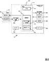
実施形態におけるQC点検用の情報処理装置を図3、図4を参照して説明する。図3は、病院等の医療機関に設置され、QC点検に係る情報を管理する情報処理装置200と、それに接続されたRFIDリーダ/ライタで構成される近接無線通信部250と、その近接無線通信部250に血糖測定装置1100をかざして通信しているシステム構成を示している。 An information processing apparatus for QC inspection in the embodiment will be described with reference to FIGS. FIG. 3 shows an
情報処理装置200は、例えばパーソナルコンピュータ等で良く、その構成は図4に示す通りである。図示において、301は装置全体の制御を司るCPUであり、302はBIOSやブートプログラムを格納しているROM、303はCPU301のワークエリアとして使用したり、OS、各種アプリケーションプログラムをロードするRAMである。304は、外部記憶装置として機能するハードディスク装置(以下、HDD)であり、これにはOS、後述する図7に係るアプリケーションプログラムを始め、図示の如く個々の血糖測定装置のQC点検に係る情報を管理するデータベース「QC管理DB」304aが予め格納されている。305はキーボード、306はマウス等のポインティングデバイス、307は液晶表示器等に代表される表示装置(表示手段)、308はネットワークインタフェース、309は血糖測定装置100と通信する近接無線通信部(具体的にはRFIDリーダ/ライタ)である。ここで、QCとは、Quality Control の略である。 The
ここで、QC点検履歴情報等を記憶する記憶手段を含むQC管理DB304aのデータ構造を図5を参照して説明する。同図に示すように、QC管理DB304aは、個々の血糖測定装置毎に情報を管理している。1つの血糖測定装置については、その血糖測定装置を特定して識別するためのデバイス識別情報(図2の符号245に対応)を格納する領域501と、過去に実施したQC点検履歴情報を格納する領域502、並びに、詳細は後述するが、将来の予測修理時期を格納する領域503で構成される。 Here, the data structure of the
ここで、QC点検履歴情報を格納する領域502は、過去のQC点検日、その際に用いた試薬サンプルに表記された血糖値(既知の血糖値)、並びに、実測した血糖値の3つのデータを1レコードとするデータ構造を成しており、QC点検日順にソートされている。なお、領域502には、該当する血糖測定装置の製造年月日を最初のQC点検日、その際に使用した試薬の血糖値を100mg/dL、実測値を100mg/dL(試薬と実測値が同じ値であれば他の値でも構わない)として登録してあるものとする。また、点検の際に用いた試薬サンプルが1種類のみの場合には、試薬サンプルの血糖値は固定値と見なして良いので、この情報は不要である。 Here, the
次に、領域503に、予測修理時期を格納する際のCPU301の処理・判断の概要を以下に説明する。 Next, an outline of the processing and determination of the
或る血糖測定装置100のQC点検を行った場合、ユーザは情報処理装置200を起動し、QC点検に係るアプリケーションを実行させる。この結果、幾つかのメニュー(不図示)が表示装置307に表示されるが、QC点検を行った場合には、ユーザがそのメニューにおける項目「QC点検データの登録」をキーボード305やポインティングデバイス306を用いて選択する。CPU301はこの項目の選択を検出すると、近接無線通信部250上に、QC点検を行った血糖測定装置100をかざすことを促すメッセージを表示装置307に表示し、通信が確立した後、血糖測定装置100からデバイス識別情報245を取得する。そしてCPU301は、取得したデバイス識別情報をキーに、それに一致する血糖測定装置をQC管理DB304aの中から特定する。そして、ユーザに対して、今回のQC点検日、使用した試薬サンプルの血糖値、及び、実測した血糖値の入力欄を含むウインドウを表示し、キーボード305やポインティングデバイス306を介して入力させる。この入力が行われると、CPU301は、今回入力したQC点検に係る情報を、領域502に追加登録すると共に、領域502に格納されたQC点検履歴に係る情報を参照し、試薬が示す血糖値と実測値との差分(の絶対値)が許容値(実施形態では20mg/dL)を超える時期を予測修理時期を演算する。そして、CPU301は、領域503に格納された前回の予測修理時期を、今回演算で求めた予測修理時期で更新すると共に、更新後の予測修理時期になったことをユーザに理解できるようなグラフを表示装置307に表示する。 When the QC check of a certain blood
図6は、表示装置207に表示されるグラフの一例を示している。図示において、水平軸が時間(日付)を、垂直軸が試薬サンプルの血糖値と実測して得られた血糖値との差分絶対値を示している。実施形態では、修理すると判定する許容範囲を既知の試薬サンプルに対して±20mg/dLを超えた場合としているので、図示の如く、20mg/dL(差分の絶対値としている点に注意された)が閾値として設定される。 FIG. 6 shows an example of a graph displayed on the display device 207. In the figure, the horizontal axis represents time (date), and the vertical axis represents the absolute difference between the blood glucose level of the reagent sample and the blood glucose level obtained by actual measurement. In the embodiment, since the allowable range to be repaired exceeds ± 20 mg / dL with respect to a known reagent sample, as shown in the figure, 20 mg / dL (note that the absolute value of the difference is used) Is set as the threshold value.
そして、図示の実線で示される折れ線601が、今回を含む過去のQC点検情報のプロットを表わしている。図示の場合、今回のQC点検が2012年2月15日に行われたことを示しているので、この日付までは実線で示される。そして、図示の破線602は、過去のQC点検に係る情報により、例えば最小二乗法により導出した予測推移を示す一次関数で示される線分である。そして、一次関数が示す直線とこの閾値とが交差する点から、水平軸に垂線を描画し、その日を含む月を予測修理時期とする。なお、何日かまで示しても良いが、その日を境に必ず異常値を測定してしまうことを意味するものではないので、図示の如く、閾値と交差する点を包含する月を最小単位として表示した。 A
なお、最小二乗法自体は公知の算出法であり、詳細は説明しないが、QC点検に係る周期は1ヶ月としているものの、人間が行うものであり、且つ、正確に1ヶ月毎に行うとは限らないし、点検を怠る月はないとも言い切れない。つまり、QC点検を御行う間隔は図示のL1、L2に示すように長い期間もあれば短い期間も有り得る。そこで、最小二乗法に適用するにあたり、領域502内の各QC点検日については、最初のQC点検日を原点とし、各々のQC点検日までに至る日数を水平軸の座標値と見なして最小二乗法により図示の破線602の一次関数を導出した。 Note that the least square method itself is a known calculation method and will not be described in detail, but although the cycle for QC inspection is set to one month, it is performed by a human and is performed accurately every month. There is no limit, and it can't be said that there are no months to neglect the inspection. That is, the interval for performing the QC check may be a long period or a short period as indicated by L1 and L2 in the figure. Therefore, when applied to the least square method, each QC inspection date in the
以上、実施形態における予測修理時期の算出とグラフ表示に係る処理を説明した。次に、これまで説明した実施形態の情報処理装置200のCPU301によるQC点検アプリケーションの処理手順を説明する。 The processing related to the calculation of the predicted repair time and the graph display in the embodiment has been described above. Next, a processing procedure of the QC inspection application by the
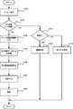
図7は、実施形態におけるQC点検アプリケーションプログラムによるCPU301の処理手順を示すフローチャートである。以下、同図のフローチャートに従い、CPU301の処理手順を説明する。 FIG. 7 is a flowchart illustrating a processing procedure of the
ユーザの指示でこのアプリケーションを実行を開始すると、CPU301は先ず、ステップS701にて、処理メニューを表示させ、その中の1つをユーザに選択させる。このメニューには、少なくとも、「QC点検データの登録」、「検索」が含まれるものとする。CPU301は、ステップS702、S703にて、どの項目が選択されたのかを判定する。 When the execution of this application is started by a user instruction, the
メニュー項目「QC点検データの登録」が選択された場合、処理はステップS704に進み、QC点検を行った血糖測定装置を近接無線通信部250にかざすよう促すメッセージを表示装置307に表示し、近接無線通信部250による血糖測定装置100との通信可能状態となるのを待つ。そして、通信可能になったときに、血糖測定装置100に対してデバイス識別情報245を要求し、受信する。そして、CPU301は、受信したデバイス識別情報に一致するデバイスに係る情報をQC点検DB304aから特定する。 When the menu item “QC check data registration” is selected, the process proceeds to step S704, and a message is displayed on the
次でステップS705に進み、CPU301は、表示装置307にQC点検日、QC点検で用いた試薬サンプルの血糖値、並びに、実測した血糖値を入力させためのウインドウを表示し、ユーザにそれらを入力させる。この入力が行われると、CPU301は、入力した情報をQC管理DB304aにおいて特定された血糖測定装置用の領域502に追加する。 In step S705, the
この後、CPU301は、ステップS706に進んで、追加後の領域502に格納された過去のQC点検に係る情報を参照し、「QC点検日(製造年月日からの日数)」をx座標値、「試薬サンプルの血糖値と実測値との差分の絶対値」をy座標値とする各座標点に近似する一次関数f(x)を最小二乗法に従って導出する。そして、求めた一次関数f(x)で示される直線と、閾値(実施形態では20mg/dLであるので、Y=20の直線)との交差する点のx座標値を求め、その交差する点のx座標値が示す「年月」を予測修理時期として算出する。そして、ステップS707にて、QC管理DB304a内の、着目している血糖測定装置に関わる領域503を、算出した予測修理時期で更新する
この後、ステップS708に進み、CPU301は、図6に示すように、実測した期間では実線で折れ線で示し、最新のQC点検日以降から将来に向かう期間では上記のようにして導出した一関数f(x)で示される直線を破線で表わすグラフを表示装置307に表示する。Thereafter, the
一方、ステップS701で表示されたメニューに対して、ユーザが「検索」を指定した場合、処理はステップS709に進み、QC管理DB304aに対して様々な検索を行う処理に移行する。検索の1つとしては、例えば期間を指定し、その期間(例えば2012年9月から10月等)に予測修理時期がある血糖測定装置を検索する、等がある。これを活用すると、例えば10月を、予測修理時期とする血糖測定装置の数を把握でき、もしその数が多い場合には、修理や部品交換の手続を事前に行う等の作業に活用することもできる。 On the other hand, when the user designates “search” for the menu displayed in step S701, the process proceeds to step S709 and shifts to a process for performing various searches on the
また、ステップS701で表示されたメニューに対して、上記以外の項目を選択した場合には、ステップS710に進み、該当する処理を行うことになるが、それは本願発明には直接には関係しないので、省略する。 If any item other than those described above is selected for the menu displayed in step S701, the process proceeds to step S710 and the corresponding processing is performed, but this is not directly related to the present invention. Omitted.
以上説明したように本実施形態によれば、血糖測定装置等の定期的な点検を必要とする生体情報測定装置に対し、各点検での既知の値を持つサンプルに対して実測値を記憶保持し、許容されるずれの範囲を超える時期を予測し、その予測結果を表示することで、部品交換や修理等の有効な事前対策が可能になる。 As described above, according to the present embodiment, for biological information measuring devices that require periodic inspection, such as blood glucose measuring devices, measured values are stored and retained for samples having known values in each inspection. By predicting the time when the allowable deviation range is exceeded and displaying the prediction result, it is possible to take effective precautions such as parts replacement and repair.
なお、実施形態では、実測したグラフの折れ線を実線、予測した関数による直線を破線で示す例を示したが、線分を別々な色、同色の色の濃淡で表現しても良い。また、実施形態では、予測修理時期を「年月」の精度で示す例を説明したが、例えば月を上旬、下旬に分けて示してもよいし、中旬を含めて3段階で示すようにしても構わない。 In the embodiment, an example in which a broken line of an actually measured graph is indicated by a solid line and a straight line by a predicted function is indicated by a broken line is shown, but the line segment may be expressed by different colors or shades of the same color. Further, in the embodiment, the example in which the predicted repair time is indicated with the accuracy of “year” has been described. However, for example, the month may be divided into the beginning and the end, or may be indicated in three stages including the middle. It doesn't matter.
また、実施形態では、QC点検で得られた情報を、QC管理DBに登録する際に、図6に示すグラフを表示するものとして説明したが、例えば、図7のステップS709における検索処理で検索して得られた中からユーザが所望とするデバイスを指定した場合に、その選択したデバイスについて図6に示すグラフを表示しても構わない。また、図6では過去の点検履歴に係る点を結ぶ折れ線を表示するものとしたのは、近似関数で示される線分のみでも構わない。ただし、導出した予測修理時期についての理解を深めるのであれば、過去の実測値の推移も合わせて表示することが望ましい。 Further, in the embodiment, the information obtained by the QC inspection has been described as displaying the graph shown in FIG. 6 when registered in the QC management DB. For example, the search is performed by the search process in step S709 in FIG. When the user designates a desired device from among the obtained devices, the graph shown in FIG. 6 may be displayed for the selected device. Further, in FIG. 6, only the line segment indicated by the approximate function may be displayed to display the broken line connecting the points related to the past inspection history. However, if you want to deepen your understanding of the derived predicted repair time, it is also desirable to display past changes in actual measured values.
また、実施形態では、QC点検データを更新する際に、その対象となる血糖測定装置を特定するために、血糖測定装置内のデバイス識別情報を通信で取得するものとした。これはユーザの操作性を向上させるために望ましいものであるが、例えば血糖測定装置にデバイス識別情報を印刷したシールを張り付けておき、ユーザがそのデバイス識別情報をキーボードから入力しても構わない。 In the embodiment, when the QC inspection data is updated, the device identification information in the blood glucose measurement device is acquired by communication in order to identify the blood glucose measurement device as a target. This is desirable for improving the operability of the user. For example, a sticker on which the device identification information is printed may be pasted on the blood glucose measurement device, and the user may input the device identification information from the keyboard.
更に、実施形態で示した各種数値(例えばQC点検の周期を1ケ月とする点、許容差分値(閾値)を20mg/dLとする点等)は、一例である。例えば、QC点検の周期を2ケ月程度にしても良いのは勿論である。 Furthermore, the various numerical values shown in the embodiment (for example, a point where the QC inspection cycle is set to one month, a point where the allowable difference value (threshold) is set to 20 mg / dL, etc.) are examples. For example, the QC inspection cycle may of course be about 2 months.
更に実施形態では、血糖測定装置100と情報処理装置200との通信として、ISO/IEC 14443に規定される非接触通信を例示したが、これは一例にすぎず、有線通信でも構わない。 Furthermore, although non-contact communication prescribed | regulated to ISO / IEC 14443 was illustrated as communication between the blood
さらにまた、実施形態では、1つの情報処理装置に、QC管理DBを保持する例を説明したが、QC管理DBを保持する装置と、それにアクセスする装置とをネットワークを介して接続するようにしても構わない。すなわち、前者をサーバ、後者を複数の端末で構成する。比較的大きな医療機関の場合には、この形態が望まれるであろう。 Furthermore, in the embodiment, the example in which the QC management DB is held in one information processing apparatus has been described. However, a device that holds the QC management DB and a device that accesses the QC management DB are connected via a network. It doesn't matter. That is, the former is composed of a server and the latter is composed of a plurality of terminals. In the case of a relatively large medical institution, this form may be desired.
また、実施形態における情報処理装置は、血糖測定装置と通信するハードを必要とするものの、その多くは、情報処理装置上で実行されるアプリケーションで実現できる。従って、本願発明は、コンピュータに実行させるためのプログラム、並びに、そのプログラムを格納したコンピュータ可読記憶媒体をその範疇とすることは明らかである。 Moreover, although the information processing apparatus in the embodiment requires hardware that communicates with the blood glucose measurement apparatus, most of the information processing apparatus can be realized by an application executed on the information processing apparatus. Therefore, it is obvious that the present invention includes a program for causing a computer to execute and a computer-readable storage medium storing the program.
以上、血糖測定装置を実施形態として説明したが、電子血圧計にも適用できる。電子血圧計の場合、図5において、試薬(mg/dL)に相当するのは圧力mmHgである。マノメータ等の標準圧力発生器を接続し、所定の圧力(mmHg)、例えば150mmHg)を発生させ、そのときの実測値(mmHg)、例えば145mmHgを得る。 As described above, the blood glucose measurement device has been described as an embodiment, but it can be applied to an electronic blood pressure monitor. In the case of an electronic sphygmomanometer, in FIG. 5, the pressure (mmHg) corresponds to the reagent (mg / dL). A standard pressure generator such as a manometer is connected to generate a predetermined pressure (mmHg), for example, 150 mmHg, and an actual measurement value (mmHg), for example, 145 mmHg is obtained.
図6において、表示装置207に表示されるグラフで、垂直軸がマノメータ等の標準圧力発生器から発生される圧力値(mmHg)と、実測して得られた圧力値(mmHg)との差分絶対値を示すことになり、例えば、±5mm/Hgを超えた場合を閾値として、上記の血糖測定装置に置き換えて、予測修理時期の算出・表示を行なうようにできる。 In FIG. 6, in the graph displayed on the display device 207, the vertical axis is the absolute difference between the pressure value (mmHg) generated from a standard pressure generator such as a manometer and the pressure value (mmHg) obtained by actual measurement. For example, the predicted repair time can be calculated / displayed by replacing the blood glucose measuring device with a threshold value exceeding ± 5 mm / Hg.
100:血糖測定装置、200:情報処理装置、250:近接無線通信部、301:CPU、302:ROM、303:RAM、304:HDD、304a:カルテDB、304b:QC管理DB、305:キーボード、306:ポインティングデバイス、307:表示装置:308:ネットワークI/F 100: blood glucose measurement device, 200: information processing device, 250: proximity wireless communication unit, 301: CPU, 302: ROM, 303: RAM, 304: HDD, 304a: medical record DB, 304b: QC management DB, 305: keyboard, 306: Pointing device, 307: Display device: 308: Network I / F
Claims (7)
Translated fromJapanese医療機器の点検実施日、並びに点検の際に用いた既知の生体情報値を持つサンプルに対して当該医療機器で実測して得た実測値とで構成される点検履歴情報を記憶する記憶手段と、
前記記憶手段を参照して、過去の各点検の実施日と前記既知の生体情報値に対するそれぞれの実測値との差分値で表わされる「実施日,差分値」のペアを、時間軸、差分値軸とする座標空間における点と見なし、当該点の集合に対して近似する線分を表わす近似関数を導出する導出手段と、
予め設定された許容差分値が定義された前記座標空間に対し、前記導出手段で導出した近似関数が示す線分をプロットした画像をグラフとして表示すると共に、前記近似関数が示す線分と前記許容差分値とが交差する点における前記時間軸上の位置を予測修理時期として表示する表示手段と
を有することを特徴とする情報処理装置。An information processing apparatus for managing an inspection history of a medical device that measures biological information of a patient,
A storage means for storing inspection history information composed of an inspection date of the medical device, and an actual measurement value obtained by actually measuring the medical device with a sample having a known biological information value used in the inspection; ,
Referring to the storage means, a pair of “implementation date, difference value” represented by a difference value between the past implementation date of each inspection and the respective actual measurement value with respect to the known biological information value is represented by a time axis, a difference value. A derivation means for deriving an approximation function representing a line segment that is regarded as a point in the coordinate space of the axis and approximates the set of points;
An image obtained by plotting the line segment indicated by the approximation function derived by the deriving unit is displayed as a graph with respect to the coordinate space in which a preset allowable difference value is defined, and the line segment indicated by the approximation function and the tolerance An information processing apparatus comprising: display means for displaying a position on the time axis at a point where a difference value intersects as a predicted repair time.
前記記憶手段を参照して、過去の各点検の実施日と前記既知の情報生体値に対するそれぞれの実測値との差分値で表わされる「実施日,差分値」のペアを、時間軸、差分値軸とする座標空間における点と見なし、当該点の集合に対して近似する線分を表わす近似関数を導出する導出工程と、
予め設定された許容差分値が定義された前記座標空間に対し、前記導出工程で導出した近似関数が示す線分をプロットした画像をグラフとして表示すると共に、前記近似関数が示す線分と前記許容差分値とが交差する点における前記時間軸上の位置を予測修理時期として表示する表示工程と
を有することを特徴とする情報処理装置の制御方法。Inspection history consisting of the inspection date of the medical device that measures the patient's biological information, and the actual measurement value obtained by actually measuring the sample with the known biological information value used in the inspection. A method for controlling an information processing apparatus that has storage means for storing information and manages an inspection history of the medical device,
Referring to the storage means, a pair of “implementation date, difference value” represented by a difference value between the past implementation date of each inspection and the respective actual measurement value with respect to the known information biometric value, a time axis, a difference value A derivation step of deriving an approximation function representing a line segment that is regarded as a point in the coordinate space of the axis and approximates the set of points;
An image obtained by plotting the line segment indicated by the approximation function derived in the derivation step is displayed as a graph with respect to the coordinate space in which a preset allowable difference value is defined, and the line segment indicated by the approximation function and the tolerance And a display step of displaying the position on the time axis at the point where the difference value intersects as the predicted repair time.
Priority Applications (1)
| Application Number | Priority Date | Filing Date | Title |
|---|---|---|---|
| JP2012066094AJP2013196629A (en) | 2012-03-22 | 2012-03-22 | Information processing apparatus and its control method, and computer program and computer-readable medium |
Applications Claiming Priority (1)
| Application Number | Priority Date | Filing Date | Title |
|---|---|---|---|
| JP2012066094AJP2013196629A (en) | 2012-03-22 | 2012-03-22 | Information processing apparatus and its control method, and computer program and computer-readable medium |
Publications (1)
| Publication Number | Publication Date |
|---|---|
| JP2013196629Atrue JP2013196629A (en) | 2013-09-30 |
Family
ID=49395428
Family Applications (1)
| Application Number | Title | Priority Date | Filing Date |
|---|---|---|---|
| JP2012066094APendingJP2013196629A (en) | 2012-03-22 | 2012-03-22 | Information processing apparatus and its control method, and computer program and computer-readable medium |
Country Status (1)
| Country | Link |
|---|---|
| JP (1) | JP2013196629A (en) |
Cited By (2)
| Publication number | Priority date | Publication date | Assignee | Title |
|---|---|---|---|---|
| WO2019239642A1 (en)* | 2018-06-12 | 2019-12-19 | オリンパス株式会社 | Medical support device and information processing device |
| JP2020513272A (en)* | 2016-12-06 | 2020-05-14 | アート メディカル リミテッドArt Medical Ltd. | System and method for sensing lung fluid |
- 2012
- 2012-03-22JPJP2012066094Apatent/JP2013196629A/enactivePending
Cited By (5)
| Publication number | Priority date | Publication date | Assignee | Title |
|---|---|---|---|---|
| JP2020513272A (en)* | 2016-12-06 | 2020-05-14 | アート メディカル リミテッドArt Medical Ltd. | System and method for sensing lung fluid |
| JP7073377B2 (en) | 2016-12-06 | 2022-05-23 | アート メディカル リミテッド | System for sensing lung fluid |
| US11678843B2 (en) | 2016-12-06 | 2023-06-20 | ART MEDICAL Ltd. | Systems and methods for sensing lung fluid and functionality |
| WO2019239642A1 (en)* | 2018-06-12 | 2019-12-19 | オリンパス株式会社 | Medical support device and information processing device |
| JPWO2019239642A1 (en)* | 2018-06-12 | 2021-06-17 | オリンパス株式会社 | Medical support device, information processing device and medical support method |
Similar Documents
| Publication | Publication Date | Title |
|---|---|---|
| US8890682B2 (en) | Blood glucose measuring device | |
| US20190243333A1 (en) | Electronic apparatus for monitoring state of machine tool and control method thereof | |
| KR102393683B1 (en) | Electronic Device including Sensor And Operating Method Thereof | |
| RU2515209C2 (en) | Disposable portable diagnostic instrument and appropriate system and method to investigate biological and natural samples | |
| EP3321768A1 (en) | Proximity sensing apparatus in electronic device and method thereof | |
| EP3055976B1 (en) | Methods and systems for a universal wireless platform for asset monitoring | |
| KR102401932B1 (en) | Electronic device measuring biometric information and method of operating the same | |
| KR20170136317A (en) | Electronic apparatus and operating method thereof | |
| JPWO2012127870A1 (en) | Biological information measuring device | |
| KR20160015809A (en) | Glucose measuring device, glucose measuring method and electronic device having clucose measuring module | |
| KR20160104976A (en) | Touch module and electronic device and operating method thereof | |
| US20200064322A1 (en) | Electronic device for measuring gas and method therefor | |
| JP5909120B2 (en) | Information processing system and apparatus, information processing apparatus control method, computer program, and computer-readable storage medium | |
| US20210228448A1 (en) | Medication reminder method, non-transitory readable storage medium storing said method, and medication reminder device | |
| KR20170101052A (en) | Electronic device and method for processing a user input in electronic device | |
| KR20170100309A (en) | Electronic apparatus for providing a voice recognition control and method thereof | |
| CN111728639A (en) | Ultrasonic tangent plane image acquisition method and device, electronic equipment and storage medium | |
| KR20150041590A (en) | Methods and systems for dynamic workflow prioritization and tasking | |
| JP2013196629A (en) | Information processing apparatus and its control method, and computer program and computer-readable medium | |
| Hartalkar et al. | Design and development of real time patient health monitoring system using Internet of Things | |
| CN112842282A (en) | Temperature measurement control method, device and system and computer readable storage medium | |
| KR20130094484A (en) | Medical instruments management system and method | |
| US20150227709A1 (en) | Network-based healthcare monitoring system | |
| KR20140141104A (en) | Smart self blood suger tester and method for measuring blood suger using mobile communication terminal | |
| CN102841353A (en) | Irradiation distance measurer and implementation method thereof |