JP2013192184A - Subject tracking display controller, subject tracking display control method, and program - Google Patents
Subject tracking display controller, subject tracking display control method, and programDownload PDFInfo
- Publication number
- JP2013192184A JP2013192184AJP2012058873AJP2012058873AJP2013192184AJP 2013192184 AJP2013192184 AJP 2013192184AJP 2012058873 AJP2012058873 AJP 2012058873AJP 2012058873 AJP2012058873 AJP 2012058873AJP 2013192184 AJP2013192184 AJP 2013192184A
- Authority
- JP
- Japan
- Prior art keywords
- subject
- tracking
- unit
- display
- display unit
- Prior art date
- Legal status (The legal status is an assumption and is not a legal conclusion. Google has not performed a legal analysis and makes no representation as to the accuracy of the status listed.)
- Granted
Links
Images


Landscapes
- Studio Devices (AREA)
Abstract
Translated fromJapaneseDescription
Translated fromJapanese本発明は、被写体の追尾機能を備える被写体追尾表示制御装置、被写体追尾表示制御方法およびプログラムに関する。 The present invention relates to a subject tracking display control device having a subject tracking function, a subject tracking display control method, and a program.
近年、撮像装置において、撮影を支援する機能として、移動する被写体の位置を順次検出して追尾する追尾機能を備えた画像処理装置が開発されている。
特許文献1では、表示画面内における追尾中の被写体の動きや位置に基づいて、追尾中の被写体の状態を示す矢印等の各種の表示情報を作成して表示部に表示させる技術が開示されている。2. Description of the Related Art In recent years, image processing apparatuses having a tracking function for sequentially detecting and tracking the position of a moving subject have been developed as functions for supporting imaging in imaging apparatuses.
しかしながら、追尾中の被写体が表示部から外に外れてしまった場合、被写体の移動方向を示す矢印を表示部に表示するようになっているものの、表示部に被写体の移動方向を矢印で表示するのみの仕様であったために、被写体の現在位置等を再度探すのに、勘に頼ってパンすることが必要であり、また、被写体を見失った後に、迅速に被写体の移動先を追尾することができないという問題点があった。 However, when the subject being tracked is outside the display unit, an arrow indicating the moving direction of the subject is displayed on the display unit, but the moving direction of the subject is displayed on the display unit with an arrow. In order to find the current position of the subject again, it is necessary to pan by relying on intuition, and it is possible to quickly track the destination of the subject after losing sight of the subject. There was a problem that it was not possible.
本発明の目的は、被写体追尾をより行い易い被写体追尾表示制御装置、被写体追尾表示制御方法およびプログラムを提供することにある。 An object of the present invention is to provide a subject tracking display control device, a subject tracking display control method, and a program that can easily perform subject tracking.
本発明は、上記目的を達成するため、
被写体を追尾する追尾手段と、
この追尾手段により追尾されている被写体の移動速度と移動方向とを検出する第1の検出手段と、
前記追尾手段により追尾されている被写体が表示部から外れたか否かを検出する第2の検出手段と、
この第2の検出手段により被写体が表示部から外れたことを検出した際に、前記第1の検出手段により検出された被写体の移動速度を示し、かつ、被写体の移動方向を示す表示情報を前記表示部に表示させる表示制御手段と、
を備えていることを特徴とする被写体追尾表示制御装置である。In order to achieve the above object, the present invention
Tracking means for tracking the subject;
First detecting means for detecting the moving speed and moving direction of the subject tracked by the tracking means;
Second detection means for detecting whether or not the subject being tracked by the tracking means has deviated from the display unit;
Display information indicating the moving speed of the subject detected by the first detecting means and indicating the moving direction of the subject when the second detecting means detects that the subject is removed from the display unit. Display control means for displaying on the display unit;
A subject tracking display control device.
また、本発明は、
被写体を追尾する追尾手段と、
この追尾手段により追尾されている被写体の移動速度と移動方向とを検出する第1の検出手段と、
前記追尾手段により追尾されている被写体が表示部から外れる直前であるのかを検出する第2の検出手段と、
前記第2の検出手段により被写体が表示部から外れる直前であることを検出した際は、表示部を広角ズームに変更させる表示制御手段と、
を備えていることを特徴とする被写体追尾表示制御装置である。The present invention also provides:
Tracking means for tracking the subject;
First detecting means for detecting the moving speed and moving direction of the subject tracked by the tracking means;
Second detection means for detecting whether the subject being tracked by the tracking means is immediately before coming off the display unit;
A display control unit for changing the display unit to a wide-angle zoom when the second detection unit detects that the subject is immediately before being removed from the display unit;
A subject tracking display control device.
また、本発明は、
被写体を追尾する追尾手段と、
この追尾手段により追尾されている被写体の移動速度と移動方向とを検出する第1の検出手段と、
前記追尾手段により追尾されている被写体が表示部から外れたか否かを検出する第2の検出手段と、
前記追尾手段により追尾されている被写体が表示部から外れる直前であるのかを検出する第3の検出手段と、
この第2の検出手段により被写体が表示部から外れたことを検出した際に、前記第1の検出手段により検出された被写体の移動速度を示し、かつ、被写体の移動方向を示す表示情報を前記表示部に表示させる一方で、前記第3の検出手段により被写体が表示部から外れる直前であることを検出した際は、表示部を広角ズームに変更させる表示制御手段と、
を備えていることを特徴とする被写体追尾表示制御装置である。The present invention also provides:
Tracking means for tracking the subject;
First detecting means for detecting the moving speed and moving direction of the subject tracked by the tracking means;
Second detection means for detecting whether or not the subject being tracked by the tracking means has deviated from the display unit;
Third detection means for detecting whether the subject being tracked by the tracking means is immediately before coming off the display unit;
Display information indicating the moving speed of the subject detected by the first detecting means and indicating the moving direction of the subject when the second detecting means detects that the subject is removed from the display unit. A display control unit for changing the display unit to a wide-angle zoom when the third detection unit detects that the subject is immediately before being removed from the display unit while displaying on the display unit;
A subject tracking display control device.
また、本発明の被写体追尾表示制御方法は、
被写体を追尾する追尾ステップと、
この追尾ステップにより追尾されている被写体の移動速度と移動方向とを検出する第1の検出ステップと、
前記追尾ステップにより追尾されている被写体が表示部から外れたか否かを検出する第2の検出ステップと、
前記被写体が前記表示部から外れたことを検出した際に、前記第1の検出ステップにより検出された被写体の移動速度を示し、かつ、被写体の移動方向を示す表示情報を前記表示部に表示させる表示制御ステップと、
を有することを特徴とする。Further, the subject tracking display control method of the present invention includes:
A tracking step for tracking the subject;
A first detection step for detecting a moving speed and a moving direction of the subject tracked by the tracking step;
A second detection step of detecting whether or not the subject being tracked by the tracking step is out of the display unit;
When it is detected that the subject has been removed from the display unit, display information indicating the moving speed of the subject detected by the first detection step and indicating the moving direction of the subject is displayed on the display unit. A display control step;
It is characterized by having.
また、本発明のプログラムは、
被写体追尾表示制御装置のコンピュータを、
被写体を追尾する追尾手段と、
この追尾手段により追尾されている被写体の移動速度と移動方向とを検出する第1の検出手段と、
前記追尾手段により追尾されている被写体が表示部から外れたか否かを検出する第2の検出手段と、
この第2の検出手段により被写体が表示部から外れたことを検出した際に、前記第1の検出手段により検出された被写体の移動速度を示し、かつ、被写体の移動方向を示す表示情報を前記表示部に表示させる表示制御手段と、
として機能させることを特徴とする。The program of the present invention is
The subject tracking display control computer
Tracking means for tracking the subject;
First detecting means for detecting the moving speed and moving direction of the subject tracked by the tracking means;
Second detection means for detecting whether or not the subject being tracked by the tracking means has deviated from the display unit;
Display information indicating the moving speed of the subject detected by the first detecting means and indicating the moving direction of the subject when the second detecting means detects that the subject is removed from the display unit. Display control means for displaying on the display unit;
It is made to function as.
本発明に従うと、被写体追尾をより行い易くすることができる。 According to the present invention, subject tracking can be made easier.
[第1の実施の形態]
まず、本発明の第1の実施の形態について図面に基づいて説明する。[First Embodiment]
First, a first embodiment of the present invention will be described with reference to the drawings.
図1は第1の実施形態に係る撮像装置100の外観を示す図であり、図1(A)は正面図、図1(B)は背面図、図1(C)は平面図である。
図1で、撮像装置100は図1(A)に示すように正面側にレンズ部としての撮像レンズ1を有している。また、撮像装置100の背面には図1(B)に示すように、モードダイアル20、表示部8、カーソルキー21、SETキー22等が設けられている。また、上面には図1(C)に示すようにズームレバー23、シャッタボタン10a及び電源ボタン24が設けられ、図示されていないが側部にはパーソナルコンピュータ(以下、パソコン)やモデム等の外部装置とUSBケーブルに接続する場合に用いるUSB端子接続部が設けられている。1A and 1B are diagrams illustrating an appearance of the
In FIG. 1, the
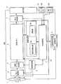
図2は、第1の実施形態に係る撮像装置100の概略構成を示すブロック図である。
図2に示すように、第1の実施形態に係る撮像装置100は、レンズ部1と、電子撮像部2と、撮像制御部3と、画像データ生成部4と、画像メモリ5と、画像処理部6と、表示制御部7と、表示部8と、記録媒体制御部9と、操作入力部10と、中央制御部11とを備えている。ここで、レンズ部1と、電子撮像部2とが撮像手段を構成する。
また、撮像制御部3と、画像処理部6と、中央制御部11は、例えば、カスタムLSI1Aとして設計されている。FIG. 2 is a block diagram illustrating a schematic configuration of the
As illustrated in FIG. 2, the
Further, the
レンズ部1は、例えば複数のレンズ玉からなるズームレンズであり、例えばフォーカシングレンズやバリエータレンズ等から構成される。
また、レンズ部1は、図示は省略するが、例えば、バリエータレンズを光軸方向に移動させるズーム駆動部、フォーカスレンズを光軸方向に移動させる合焦駆動部等を備えている。The
Although not shown, the
電子撮像部2は、例えば、CCD(Charge Coupled Device)やCMOS(Complementary Metal-oxide Semiconductor)等のイメージセンサから構成され、レンズ部1の各種レンズを通過した光学像を二次元の画像信号に変換する。 The
撮像制御部3は、図示は省略するが、タイミング発生器、ドライバなどを備えている。そして、撮像制御部3は、タイミング発生器、ドライバにより電子撮像部2を走査駆動して、所定周期毎に光学像を電子撮像部2により二次元の画像信号に変換させ、当該電子撮像部2の撮像領域から1画面分ずつ画像フレームを読み出して画像データ生成部4に逐次出力させる。
また、撮像制御部3は、AF(自動合焦処理)、AE(自動露出処理)、AWB(自動ホワイトバランス)等の被写体の撮像条件の調整制御を行う。Although not shown, the
In addition, the
画像データ生成部4は、電子撮像部2から転送された画像フレームのアナログ値の信号に対してRGBの色成分毎に適宜ゲイン調整した後に、サンプルホールド回路(図示略)でサンプルホールドしてA/D変換器(図示略)でデジタルデータに変換し、カラープロセス回路(図示略)で画素補間処理及びγ補正処理を含むカラープロセス処理を行った後、デジタル値の輝度信号Y及び色差信号Cb,Cr(YUVデータ)を画像データとして生成する。
カラープロセス回路から出力される画像データは、図示しないDMAコントローラを介して、バッファメモリとして使用される画像メモリ5にDMA転送される。The image
Image data output from the color process circuit is DMA transferred to an
中央制御部11は、撮像装置100の各部を制御するものである。具体的には、中央制御部11は、CPU、RAM、ROM(何れも図示略)を備え、撮像装置100用の各種処理プログラム(図示略)に従って各種の制御動作を行う。 The
画像メモリ5は、例えば、DRAM等により構成され、画像データ生成部4から転送された画像データを一時的に記憶する。また、画像メモリ5は、画像処理部6や中央制御部11等によって処理されるデータ等を一時的に記憶する。 The
画像処理部6は、被写体検出部6aと、追尾部6bを具備している。 The
被写体検出部6aは、被写体Hの顔または体全体を検出する被写体検出手段を有する。被写体検出手段は、画像メモリ5から画像を読み出し、その画像から人の顔等を検出し、検出された顔等の位置や大きさ等を特定する。被写体検出部6aは、撮像された画像データの全領域(画角の全範囲)内に人の顔があるか否かを認識する。つまり、顔認識処理の対象となる範囲は画像データの全領域である。 The
この被写体検出部6aは、例えば、画像領域に含まれる人の顔を識別するための一般的な人の顔の特徴点データ(目、眉毛、鼻、口、耳等の特徴データ)と撮像された画像データとを比較照合することによって、顔を検出ように構成されている。 The
また、この被写体検出部6aは、一方の眼を検出し、該一方の眼に基づいて両眼対候補を生成することによって、顔を検出するように構成されてもよい。
また、この被写体検出部6aは、顔全体の輪郭に対応した基準テンプレートを用いたテンプレートマッチング(ブロックマッチングともいう。)によって顔を検出するように構成されてもよい。The
The
また、被写体検出部6aは、被写体Hの形状の特徴領域を表す形状情報を特徴点として抽出する。この場合、被写体検出部6aは、画像データから被写体Hの輪郭を形状情報として抽出する。 In addition, the
追尾部6bは、画像データの全領域内を移動する被写体Hを追尾する。この追尾部6bは、動き検出手段と動き推定手段とを有する。ここで、追尾部6bは追尾手段を構成する。 The
追尾部6bは、撮像された画像データの全領域(画角の全範囲)における物体の移動における動きを検出する。具体的には、画像メモリ5から読み出された画像のフレーム間差分を画素単位で求め、差分のあった画素領域に動きのある移動物体が存在すると推定するフレーム間差分方式を用いて、物体の動きを検出する。
また、前フレームで動きと推定された領域を切り出してテンプレート画像とし、現フレームでこのテンプレート画像と相関の高い領域を探索し、相関値が閾値以上である領域を移動物体が存在する領域であると推定するマッチング方式を用いて、物体の動きを検出することもできる。The
In addition, a region estimated as motion in the previous frame is cut out as a template image, a region having a high correlation with this template image is searched in the current frame, and a region where the correlation value is equal to or greater than a threshold is a region where a moving object exists. It is also possible to detect the motion of an object using a matching method that estimates that.
また、追尾部6bは、動き検出手段が検出する動きベクトルに基づいて、被写体Hの速さ及び被写体Hの動く方向を予測する。 Further, the
表示制御部7は、画像メモリ5に記憶されている縮小画像データを読み出して表示部8に縮小画像を表示させる制御を行う。
具体的には、表示制御部7は、VRAM、VRAMコントローラ、デジタルビデオエンコーダなどを備えている。そして、デジタルビデオエンコーダは、中央制御部11の制御下にて画像メモリ5から読み出されてVRAM(図示略)に記憶されている縮小画像データの輝度信号Y及び色差信号Cb,Crを、VRAMコントローラを介してVRAMから定期的に読み出して、これらのデータを元にビデオ信号を発生して表示部8に出力する。また、表示制御部7は、撮像モードにて、電子撮像部2及び撮像制御部3による撮像により生成された複数の画像フレームに基づいたライブビュー画像や、本撮像画像として撮像されたレックビュー画像等を表示部8に表示させる機能も有する。The
Specifically, the
表示部8は、例えば、液晶表示装置であり、表示制御部7からのビデオ信号に基づいて縮小画像を表示する表示手段として機能している。また、表示部8は、表示制御部7からのビデオ信号に基づいて、ライブビュー画像、レックビュー画像、合成画像等を表示部8に表示する。 The
記録媒体制御部9は、記録媒体9aが着脱自在に構成され、装着された記録媒体9aからのデータの読み出しや記録媒体9aに対するデータの書き込みを制御する。即ち、記録媒体制御部9は、画像処理部6のJPEG圧縮部(図示略)により符号化された記録用の画像データを記録媒体9aに記録させる。記録用の画像データには、切抜画像データも含まれる。 The recording medium control unit 9 is configured so that the
なお、記録媒体9aは、例えば、不揮発性メモリ(フラッシュメモリ)等により構成されるが、一例であってこれに限られるものではなく、適宜任意に変更可能である。 The
操作入力部10は、当該撮像装置100の所定操作を行うためのものである。具体的には、操作入力部10は、被写体Hの撮影指示に係るシャッタボタン10a、各種の指示ボタン10bを備える。指示ボタン10bは、モードダイアル20、カーソルキー21、SETキー22、ズームレバー23等に対応する。それらは、メニュー画面にて撮像モードや機能等の選択や構図の指示等を行い、また、ズーム量の調整指示を行う。これらのボタンの操作に応じて所定の操作信号を中央制御部11に出力する。 The
また、操作入力部10は、各種の設定に係る指示入力を行うためのものとして機能する。 Further, the
次に、第1の実施形態に係る撮像装置100の動作について説明する。
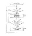
図3は、第1の実施形態において実行される「自動追尾処理1」の制御手順を示すフローチャートである。図4は、「自動追尾処理1」における表示画面を示す例である。
以下、撮像装置100による「自動追尾処理1」の動作について図3のフローチャートおよび図4を参照して説明する。Next, the operation of the
FIG. 3 is a flowchart showing a control procedure of “
Hereinafter, the operation of “
「自動追尾処理1」の処理が開始されると中央制御部11は先ず、被写体検出部6aによる被写体分析を行い、追尾部6bは、被写体追尾を行う(ステップS01)。その結果、被写体追尾中である場合は、「YES」へ分岐してステップS02に移行する。一方、被写体追尾中でない場合は、「NO」へ分岐してステップS01に移行する。When the “
また、追尾が開始されると、中央制御部11は、追尾部6bにより、被写体Hの移動速度、移動方向の検出を開始する。そして、追尾が実施されている間、被写体Hの移動速度、移動方向の検出を継続する。
ここで、中央制御部11は、被写体Hの移動速度と移動方向とを検出する第1の検出手段を構成する。When tracking is started, the
Here, the
ステップS02では、中央制御部11は、追尾部6bを制御して、把握された被写体Hの顔または体全体を囲む追尾被写枠25を表示させる。
図4(A)〜図4(C)は被写体Hに追尾被写枠25が表示されている様子を示す。In step S02, the
4A to 4C show a state in which the tracking
ステップS03では、被写体Hの追尾中に、被写体Hが移動し、表示部8から外れたか否かを判断する。被写体追尾中に、被写体Hが移動し、表示部8から外れた場合には、「YES」へ分岐してステップS04に移行する。表示部8から外れていない場合には、「NO」へ分岐してステップS02に移行する。
図4(D)は、被写体Hが表示部8から外れた場合を示している。
ここで、中央制御部11は、前記被写体Hを追尾中に、被写体Hが表示部8から外れたか否かを検出する第2の検出手段を構成する。In step S <b> 03, it is determined whether or not the subject H has moved and removed from the
FIG. 4D shows a case where the subject H is detached from the
Here, the
ステップS04では、中央制御部11は、直前の被写体Hの移動速度とその移動方向を、追尾部6bから取得して、その移動速度とその移動方向を、移動速度に対応した長さLで、かつ、移動方向の向きの矢印Yとして前記表示部8に表示する。表示方法は、例えば、矢印Yの向きで方向を、矢印Yの長さLで移動速度を示す。
ここで、第1の実施形態における直前の被写体Hとは、例えば、被写体追尾が行われていた最後の画像フレームにおける被写体である。
また、中央制御部11は、追尾部6bにより検出された被写体Hの移動速度に対応した長さで、かつ、被写体Hの移動方向の向きの矢印Yを表示部8上に表示させる表示制御手段を構成する。
また、図4(D)は、その移動速度とその移動方向を示す矢印Yが前記表示部8上に表示されている様子を示す。In step S04, the
Here, the immediately preceding subject H in the first embodiment is, for example, the subject in the last image frame in which subject tracking has been performed.
In addition, the
FIG. 4D shows a state where an arrow Y indicating the moving speed and the moving direction is displayed on the
以上のように、第1の実施形態によれば、撮像装置100は、被写体Hを追尾する追尾部6bと、この追尾部6bにより追尾されている被写体Hの移動速度と移動方向とを検出する第1の検出手段11と、追尾部6bにより追尾されている被写体Hが表示部から外れたか否かを検出する第2の検出手段11と、第2の検出手段11により被写体Hが表示部8から外れたことを検出した際に、第1の検出手段11により検出された被写体Hの移動速度を示し、かつ、被写体Hの移動方向を示す表示情報を表示部8に表示させる表示制御手段11と、を備えており、撮像装置100のこれらの構成要素は被写体追尾表示制御装置として機能している。
そして、追尾部6bで被写体Hを追尾しながら、被写体Hの移動速度と移動方向とを検出し、被写体Hが表示部8から外れたか否かを検出し、被写体Hが表示部8から外れたことを検出した際に、被写体Hの移動速度に対応した長さLで、かつ、被写体Hの移動方向の向きの矢印Yを前記表示部8に表示させるようにしているので、被写体Hが移動し、表示部8の表示部から外れてしまった場合、その被写体Hの直前のベクトル情報(方向、速度)を表示することができる。したがって、撮影者は、被写体Hを見失っても、矢印Yの向きとその長さLとの双方を目で確認することができ、撮像装置100の向きを、どちらの方向に、おおよそ、どの程度、動かせば再び表示部8内に被写体Hを入れることができるか、瞬間的に把握できる。As described above, according to the first embodiment, the
Then, while tracking the subject H by the
また、表示情報は、第1の検出手段11により検出された被写体Hの移動速度に対応した長さLを示し、かつ、被写体の移動方向の向きを示す矢印Yであるので、表示情報がわかりやすい。 The display information is a length L corresponding to the moving speed of the subject H detected by the
[第2の実施の形態]
次に、本発明の第2の実施形態について説明する。[Second Embodiment]
Next, a second embodiment of the present invention will be described.
上述した第1の実施形態では、被写体追尾中に、被写体Hが移動し、表示部8から外れてしまった場合に矢印Yの表示を行う例を説明したが、第2の実施形態ではレンズ部1のズーム倍率を変更する例を説明する。 In the first embodiment described above, the example in which the arrow Y is displayed when the subject H moves and is detached from the
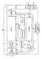
図5は、第2の実施形態に係る撮像装置200の概略構成を示すブロック図である。実施形態2の撮像装置200は、以下に詳細に説明する以外の点で上記実施形態1の撮像装置100と略同様の構成をなし、詳細な説明は省略する。撮像装置200の外観は図1と同様であり、図示と説明は省略する。 FIG. 5 is a block diagram illustrating a schematic configuration of the
第2の実施形態に係る撮像装置200では、図2に示した撮像装置200の構成に追尾ズーム制御部12が追加されている。追尾ズーム制御部12は、中央制御部31の制御を受けて、下記の「自動追尾処理2」に応じてレンズ部1のズーム駆動部を制御する。また、撮像制御部3と、追尾ズーム制御部12と、画像処理部6と、中央制御部31は、例えば、カスタムLSI1Bとして設計されている。 In the
次に、第2の実施の形態に係る撮像装置200の動作について説明する。 Next, the operation of the
図6は、第2の実施の形態において実行される「自動追尾処理2」の制御手順を示すフローチャートである。図7は、「自動追尾処理2」における表示画面の遷移を示す例である。
以下、撮像装置200による「自動追尾処理2」の動作について図6のフローチャートおよび図7を参照して説明する。FIG. 6 is a flowchart showing a control procedure of “
Hereinafter, the operation of the “
「自動追尾処理2」の処理が開始されると中央制御部31は先ず、被写体検出部6aによる被写体分析を行い、被写体追尾を行う(ステップS01)。その結果、被写体追尾中である場合は、「YES」へ分岐してステップS12に移行する。一方、被写体追尾中でない場合は、「NO」へ分岐してステップS11に移行する。
ここで、中央制御部31は、被写体Hの移動速度と移動方向とを検出する第1の検出手段を構成する。When the “
Here, the
ステップS12では、中央制御部31は、追尾部6bを制御して、把握された被写体Hに追尾被写枠25を表示させる。
図7(A)〜図7(B)は被写体Hに追尾被写枠25が表示されて、被写体Hが追尾されている様子を示している。In step S12, the
FIGS. 7A to 7B show a state in which the tracking
ステップ13では、中央制御部31は、追尾部6bを制御して、「広角ズーム前の画角から被写体Hが外れる直前か否か判断する。ここで、広角ズーム前の画角とは、ステップS14で実施する広角ズームアウト処理前の現在のレンズの画角を意味する。被写体追尾中に、被写体Hが移動し、「広角ズーム前の画角から被写体Hが外れる直前である場合には、「YES」へ分岐してステップS14に移行する。「広角ズーム前の画角から被写体Hが外れる直前ではない場合には、「NO」へ分岐してステップS12に移行する。 In step 13, the
広角ズーム前の画角から被写体Hが外れる直前か否か判断手法は、以下の通りである。すなわち、被写体Hが、所定の時間後に、速度とその方向とから計算して外れると想定されるときを、外れる直前であるとする。
具体的には、動き推定手段は、動き検出手段が検出する動きベクトルに基づいて、被写体Hの速度及び被写体Hの動く方向を予測し、所定時間(例えば0.5秒)後に表示部8の表示画面部から外れてしまうと予測される場合を外れる直前であるとする。A method for determining whether or not the subject H is just outside the angle of view before the wide-angle zoom is as follows. That is, when it is assumed that the subject H is deviated from the speed and its direction after a predetermined time, it is assumed that it is immediately before deviating.
Specifically, the motion estimation unit predicts the speed of the subject H and the moving direction of the subject H based on the motion vector detected by the motion detection unit, and after a predetermined time (for example, 0.5 seconds), It is assumed that it is immediately before the case where it is predicted that the display screen will be removed.
また、例えば、被写体Hが人間である場合には、顔全体の所定の割合、例えば20%が表示部8の表示画面部から外れてしまった状態、または、顔の両眼の内、片側の眼が認識できなかった場合を直前と定義することができる。さらには、当初の追尾被写枠の所定の割合、例えば20%が表示部8の表示画面部から外れてしまった状態、または、追尾被写枠を認識する要素が不安定になった状態を直前と定義することもできる。 Further, for example, when the subject H is a human, a predetermined ratio, for example, 20% of the entire face has been removed from the display screen portion of the
また、例えば、画面中心から表示部8の表示画面部までの距離の9割を越えた周辺に至ったときを直前であるとすることもできる。
ここで、中央制御部31は、被写体Hを追尾中に、被写体Hが表示画面部から外れる直前であるのかを検出する第2の検出手段である。In addition, for example, it may be determined that the time immediately before reaching the periphery exceeding 90% of the distance from the center of the screen to the display screen portion of the
Here, the
ステップS14では、中央制御部31は、追尾ズーム制御部12を制御して、「広角へズームアウト処理」を行う。「広角へズームアウト処理」とは、中央制御部31の制御を受けた追尾ズーム制御部12が、レンズ部1のズーム駆動部を制御してズームレンズの焦点距離を小さく変更する処理である。
図7(C)では、被写体Hが表示画面から外れる直前である状態が例示されている。直前であるかの判断手法は、「被写体Hの速度及び被写体Hの動く方向を予測し、所定時間(例えば0.5秒)後に表示部8の表示画面部から外れてしまうと予測される場合」である。そして、ステップS13にて直前であることが検出され、ステップS14にて「広角へズームアウト処理」が行われる。図7(D)においてズーム前の画面が点線T1で、ズーム後の画面が実線T2で示されている。ズームされたことにより、ズーム後の表示画面部の内部に被写体Hが留まっている。
ここで、中央制御部31、追尾ズーム制御部12が、第3の検出手段により被写体Hが表示画面部から外れる直前であることを検出したときに表示画面部を広角ズームに変更させる表示制御手段である。In step S <b> 14, the
FIG. 7C illustrates a state in which the subject H is just before being removed from the display screen. The determination method of whether or not it is immediately before is “when the speed of the subject H and the moving direction of the subject H are predicted, and the display screen portion of the
Here, when the
以上のように、第2の実施形態によれば、撮像装置200は、被写体を追尾する追尾部6bと、この追尾部6bにより追尾されている被写体の移動速度と移動方向とを検出する第1の検出手段31と、追尾部6bにより追尾されている被写体が表示部8から外れる直前であるのかを検出する第2の検出手段31と、第2の検出手段31により被写体が表示部8から外れる直前であることを検出した際は、表示部8を広角ズームに変更させる表示制御手段31、12と、を備えており、撮像装置200のこれらの構成要素は被写体追尾表示制御装置として機能している。
そして、被写体Hを追尾しながら、その被写体Hの移動速度と移動方向とを検出し、被写体Hが表示部8から外れる直前なのかを検出し、被写体Hが表示部8から外れる直前であることを検出した際は、表示部8を広角ズームに変更させるようにしているので、撮影者は、広角ズーム処理により被写体Hを逃がすことなく動画・静止画撮影や撮影チャンスを待つ等の行為を行うことができる。As described above, according to the second embodiment, the
Then, while tracking the subject H, the moving speed and moving direction of the subject H are detected, whether the subject H is just before the
[第3の実施の形態]
次に、本発明の第3の実施形態について説明する。[Third Embodiment]
Next, a third embodiment of the present invention will be described.
第3の実施形態では、被写体追尾中に、レンズ部1のズーム倍率を変更するとともに、被写体Hが移動し、表示画面から外れてしまった場合に所定の表示を行う例を説明する。
図8は、第3の実施形態に係る撮像装置300の概略構成を示すブロック図である。実施形態3の撮像装置300は、以下に詳細に説明する以外の点で上記実施形態1の撮像装置100と略同様の構成をなし、詳細な説明は省略する。撮像装置300の外観は図1と同様であり、図示と説明は省略する。In the third embodiment, an example will be described in which the zoom magnification of the
FIG. 8 is a block diagram illustrating a schematic configuration of an
第3の実施形態に係る撮像装置300では、図2に示した撮像装置100の構成に追尾ズーム制御部12が追加されている。追尾ズーム制御部12は、中央制御部41の制御を受けて、下記の「自動追尾処理2」に応じてレンズ部1のズーム駆動部を制御する。また、撮像制御部3と、追尾ズーム制御部12と、画像処理部6と、中央制御部41は、例えば、カスタムLSI1Cとして設計されている。 In the
図9は、第3の実施形態において実行される「自動追尾処理3」の制御手順を示すフローチャートである。図10は、「自動追尾処理3」における表示画面を示す例である。
以下、撮像装置300による「自動追尾処理3」の動作について図9のフローチャートおよび図10を参照して説明する。FIG. 9 is a flowchart showing a control procedure of “
Hereinafter, the operation of the “
「自動追尾処理3」の処理が開始されると中央制御部41は先ず、被写体検出部6aによる被写体分析を行い、被写体追尾を行う(ステップS21)。その結果、被写体追尾中である場合は、「YES」へ分岐してステップS222に移行する。その結果、被写体追尾中でない場合は、「NO」へ分岐してステップS21に移行する。 When the “
また、追尾部6bは、追尾が開始されると、被写体Hの移動速度、移動方向の検出を開始する。そして、追尾が実施されている間、被写体Hの移動速度、移動方向の検出を継続する。
ここで、中央制御部41は、被写体Hの移動速度と移動方向とを検出する第1の検出手段を構成する。Further, when tracking is started, the
Here, the
ステップS22では、中央制御部41は、追尾部6bを制御して、把握された被写体Hに追尾被写枠を表示させる。
図10(A)(B)は被写体Hに追尾被写枠25が表示されている様子を示す。In step S22, the
FIGS. 10A and 10B show the tracking
ステップ23では、中央制御部41は、追尾部6bを制御して、「広角ズーム前の画角から被写体Hが外れる直前か否か判断する。ここで、広角ズーム前の画角とは、ステップS24で実施する広角ズームアウト処理前の現在のレンズの画角を意味する。被写体追尾中に、被写体Hが移動し、「広角ズーム前の画角から被写体Hが外れる直前である場合には、「YES」へ分岐してステップS24に移行する。「広角ズーム前の画角から被写体Hが外れる直前ではない場合には、「NO」へ分岐してステップS22に移行する。判断手法としては、第2の実施の形態と同じ手法が挙げられる。
ここで、中央制御部41が、被写体Hを追尾中に、被写体Hが表示画面部から外れる直前であるのかを検出する第3の検出手段である。In
Here, the
ステップ24では、中央制御部41は、追尾ズーム制御部12を制御して、「広角へズームアウト処理を行う。ズームアウト処理とは、中央制御部41の制御を受けた追尾ズーム制御部12が、レンズ部1のズーム駆動部を制御してズームレンズの焦点距離を小さく変更する処理である。
ここで、中央制御部41、追尾ズーム制御部12が、被写体Hが表示画面部から外れる直前であることを検出した際に表示画面部を広角ズームに変更させる表示制御手段である。
図10(C)においてズーム前の画面が点線で、ズーム後の画面が実線で示されている。図10(C)の実線に示すように被写体Hは、ズームが行われたことにより、表示部8の広角ズーム処理の処理後の表示部8の内部に留まっている。In
Here, when the
In FIG. 10C, the screen before zooming is indicated by a dotted line and the screen after zooming is indicated by a solid line. As shown by the solid line in FIG. 10C, the subject H remains inside the
ステップS25では、中央制御部41は、被写体検出部6aによる被写体分析を行い、被写体追尾を行う。その結果、被写体追尾中である場合は、「YES」へ分岐してステップS22に移行する。その結果、被写体追尾中でない場合は、「NO」へ分岐してステップS26に移行する。 In step S25, the
ステップS26では、中央制御部41は、直前の被写体Hの移動速度とその移動方向とを、追尾部6bから取得して、その移動速度とその移動方向とを、移動速度に対応した長さLで、かつ、被写体Hの移動方向の向きの矢印Yとして前記表示部8に表示する。表示方法は、矢印Yの向きで方向を、矢印Yの長さYで移動速度を示す。
ここで、第3の実施形態における直前の被写体Hとは、例えば、被写体追尾が行われていた最後の画像フレームにおける被写体である。
ここで、中央制御部41は、前記被写体Hを追尾中に、被写体Hが表示部8から外れたか否かを検出する第2の検出手段を構成する。
また、中央制御部41は、追尾部6bにより検出された被写体Hの移動速度に対応した長さLで、かつ、被写体Hの移動方向の向きの矢印Yを表示部8に表示させる表示制御手段である。
また、図10(D)は、その移動速度とその移動方向とを示す矢印Yが前記表示部8に表示されている様子を示す。In step S26, the
Here, the immediately preceding subject H in the third embodiment is, for example, the subject in the last image frame in which subject tracking has been performed.
Here, the
Further, the
FIG. 10D shows a state in which an arrow Y indicating the moving speed and the moving direction is displayed on the
以上のように、第3の実施形態によれば、撮像装置300は、被写体を追尾する追尾部6bと、この追尾部6bにより追尾されている被写体Hの移動速度と移動方向とを検出する第1の検出手段41と、追尾手段により追尾されている被写体が表示部8から外れたか否かを検出する第2の検出手段41と、追尾手部6bにより追尾されている被写体Hが表示部8から外れる直前であるのかを検出する第3の検出手段41と、この第2の検出手段41により被写体Hが表示部8から外れたことを検出した際に、第1の検出手段41により検出された被写体Hの移動速度を示し、かつ、被写体Hの移動方向を示す表示情報を前記表示部8に表示させる一方で、第3の検出手段41により被写体Hが表示部8から外れる直前であることを検出した際は、表示部8を広角ズームに変更させる表示制御手段41、12と、を備えており、撮像装置300のこれらの構成要素は被写体追尾表示制御装置として機能している。
したがって、撮影者は、広角ズーム処理により被写体Hを逃がすことなく動画・静止画撮影や撮影チャンスを待つ等の行為を行うことができる。さらに、広角ズーム処理によっても、被写体Hが画面内に検出されない場合には、その被写体Hの直前のベクトル情報(方向、速度)を画面上に表示することができる。したがって、撮影者は、被写体Hを見失っても、表示部8に表示された矢印Yから、撮像装置300の向きを、どちらの方向に、おおよそ、どの程度、動かせば再び表示部8内に入れることができるか、瞬間的に把握できる。As described above, according to the third embodiment, the
Therefore, the photographer can perform actions such as moving image / still image shooting or waiting for a shooting opportunity without missing the subject H by the wide-angle zoom processing. Furthermore, when the subject H is not detected in the screen even by the wide-angle zoom process, the vector information (direction and speed) immediately before the subject H can be displayed on the screen. Therefore, even if the photographer loses sight of the subject H, the direction of the
本発明の実施形態を説明したが、本発明の範囲は上述の実施の形態に限定するものではなく、特許請求の範囲に記載された発明とその均等の範囲に含まれる。
例えば、被写体が表示部から外れたことを検出した際に、検出された被写体の移動速度を示し、かつ、被写体の移動方向を示す表示情報として、検出された被写体の移動速度に対応した長さを示し、かつ、被写体の移動方向の向きを示す矢印を用いていたが、被写体の移動方向の向きを示す矢印の近傍位置に、検出された被写体の移動速度を示す速度データを表示してもよい。また、矢印に代えて、文字データで、検出された被写体の移動速度を示し、かつ、被写体の移動方向を示してもよい。
以下に、本願出願の当初の特許請求の範囲に記載された発明を付記する。
[付記]
<請求項1>
被写体を追尾する追尾手段と、
この追尾手段により追尾されている被写体の移動速度と移動方向とを検出する第1の検出手段と、
前記追尾手段により追尾されている被写体が表示部から外れたか否かを検出する第2の検出手段と、
この第2の検出手段により被写体が表示部から外れたことを検出した際に、前記第1の検出手段により検出された被写体の移動速度を示し、かつ、被写体の移動方向を示す表示情報を前記表示部に表示させる表示制御手段と、
を備えていることを特徴とする被写体追尾表示制御装置。
<請求項2>
前記表示情報は、前記第1の検出手段により検出された被写体の移動速度に対応した長さを示し、かつ、被写体の移動方向の向きを示す矢印であることを特徴とする請求項1記載の被写体追尾表示制御装置。
<請求項3>
被写体を追尾する追尾手段と、
この追尾手段により追尾されている被写体の移動速度と移動方向とを検出する第1の検出手段と、
前記追尾手段により追尾されている被写体が表示部から外れる直前であるのかを検出する第2の検出手段と、
前記第2の検出手段により被写体が表示部から外れる直前であることを検出した際は、表示部を広角ズームに変更させる表示制御手段と、
を備えていることを特徴とする被写体追尾表示制御装置。
<請求項4>
被写体を追尾する追尾手段と、
この追尾手段により追尾されている被写体の移動速度と移動方向とを検出する第1の検出手段と、
前記追尾手段により追尾されている被写体が表示部から外れたか否かを検出する第2の検出手段と、
前記追尾手段により追尾されている被写体が表示部から外れる直前であるのかを検出する第3の検出手段と、
この第2の検出手段により被写体が表示部から外れたことを検出した際に、前記第1の検出手段により検出された被写体の移動速度を示し、かつ、被写体の移動方向を示す表示情報を前記表示部に表示させる一方で、前記第3の検出手段により被写体が表示部から外れる直前であることを検出した際は、表示部を広角ズームに変更させる表示制御手段と、
を備えていることを特徴とする被写体追尾表示制御装置。
<請求項5>
被写体を追尾する追尾ステップと、
この追尾ステップにより追尾されている被写体の移動速度と移動方向とを検出する第1の検出ステップと、
前記追尾ステップにより追尾されている被写体が表示部から外れたか否かを検出する第2の検出ステップと、
前記被写体が前記表示部から外れたことを検出した際に、前記第1の検出ステップにより検出された被写体の移動速度を示し、かつ、被写体の移動方向を示す表示情報を前記表示部に表示させる表示制御ステップと、
を有することを特徴とする被写体追尾表示制御方法。
<請求項6>
被写体追尾表示制御装置のコンピュータを、
被写体を追尾する追尾手段と、
この追尾手段により追尾されている被写体の移動速度と移動方向とを検出する第1の検出手段と、
前記追尾手段により追尾されている被写体が表示部から外れたか否かを検出する第2の検出手段と、
この第2の検出手段により被写体が表示部から外れたことを検出した際に、前記第1の検出手段により検出された被写体の移動速度を示し、かつ、被写体の移動方向を示す表示情報を前記表示部に表示させる表示制御手段と、
として機能させることを特徴とするプログラム。Although the embodiment of the present invention has been described, the scope of the present invention is not limited to the above-described embodiment, and is included in the invention described in the claims and the equivalent scope thereof.
For example, when it is detected that the subject has been removed from the display unit, the length corresponding to the detected moving speed of the subject is displayed as display information indicating the moving speed of the detected subject and the moving direction of the subject. And an arrow indicating the direction of movement of the subject is used, but speed data indicating the detected moving speed of the subject may be displayed near the arrow indicating the direction of movement of the subject. Good. Further, instead of the arrow, the detected moving speed of the subject and the moving direction of the subject may be indicated by character data.
Hereinafter, the invention described in the scope of claims of the present application will be appended.
[Appendix]
<Claim 1>
Tracking means for tracking the subject;
First detecting means for detecting the moving speed and moving direction of the subject tracked by the tracking means;
Second detection means for detecting whether or not the subject being tracked by the tracking means has deviated from the display unit;
Display information indicating the moving speed of the subject detected by the first detecting means and indicating the moving direction of the subject when the second detecting means detects that the subject is removed from the display unit. Display control means for displaying on the display unit;
An object tracking display control apparatus comprising:
<Claim 2>
2. The display information according to
<Claim 3>
Tracking means for tracking the subject;
First detecting means for detecting the moving speed and moving direction of the subject tracked by the tracking means;
Second detection means for detecting whether the subject being tracked by the tracking means is immediately before coming off the display unit;
A display control unit for changing the display unit to a wide-angle zoom when the second detection unit detects that the subject is immediately before being removed from the display unit;
An object tracking display control apparatus comprising:
<Claim 4>
Tracking means for tracking the subject;
First detecting means for detecting the moving speed and moving direction of the subject tracked by the tracking means;
Second detection means for detecting whether or not the subject being tracked by the tracking means has deviated from the display unit;
Third detection means for detecting whether the subject being tracked by the tracking means is immediately before coming off the display unit;
Display information indicating the moving speed of the subject detected by the first detecting means and indicating the moving direction of the subject when the second detecting means detects that the subject is removed from the display unit. A display control unit for changing the display unit to a wide-angle zoom when the third detection unit detects that the subject is immediately before being removed from the display unit while displaying on the display unit;
An object tracking display control apparatus comprising:
<Claim 5>
A tracking step for tracking the subject;
A first detection step for detecting a moving speed and a moving direction of the subject tracked by the tracking step;
A second detection step of detecting whether or not the subject being tracked by the tracking step is out of the display unit;
When it is detected that the subject has been removed from the display unit, display information indicating the moving speed of the subject detected by the first detection step and indicating the moving direction of the subject is displayed on the display unit. A display control step;
An object tracking display control method characterized by comprising:
<Claim 6>
The subject tracking display control computer
Tracking means for tracking the subject;
First detecting means for detecting the moving speed and moving direction of the subject tracked by the tracking means;
Second detection means for detecting whether or not the subject being tracked by the tracking means has deviated from the display unit;
Display information indicating the moving speed of the subject detected by the first detecting means and indicating the moving direction of the subject when the second detecting means detects that the subject is removed from the display unit. Display control means for displaying on the display unit;
A program characterized by functioning as
100、200、300 撮像装置
1 レンズ部(撮像手段)
2 電子撮像部(撮像手段)
3 撮像制御部
4 画像データ生成部
5 画像メモリ
6 画像処理部
6a 被写体検出部
6b 追尾部(追尾手段)
7 表示制御部
8 表示部
9 記録媒体制御部
10 操作入力部
10a シャッタボタン
10b 指示ボタン
11、31、41 中央制御部(第1の検出手段、第2の検出手段、第3の検出手段、表示制御手段)
12 追尾ズーム制御部(表示制御手段)
20 モードダイアル
21 カーソルキー
22 セットキー
23 ズームレバー
24 電源ボタン
25 追尾被写枠100, 200, 300
2 Electronic imaging unit (imaging means)
3
7
12 Tracking zoom control unit (display control means)
20
Claims (6)
Translated fromJapaneseこの追尾手段により追尾されている被写体の移動速度と移動方向とを検出する第1の検出手段と、
前記追尾手段により追尾されている被写体が表示部から外れたか否かを検出する第2の検出手段と、
この第2の検出手段により被写体が表示部から外れたことを検出した際に、前記第1の検出手段により検出された被写体の移動速度を示し、かつ、被写体の移動方向を示す表示情報を前記表示部に表示させる表示制御手段と、
を備えていることを特徴とする被写体追尾表示制御装置。Tracking means for tracking the subject;
First detecting means for detecting the moving speed and moving direction of the subject tracked by the tracking means;
Second detection means for detecting whether or not the subject being tracked by the tracking means has deviated from the display unit;
Display information indicating the moving speed of the subject detected by the first detecting means and indicating the moving direction of the subject when the second detecting means detects that the subject is removed from the display unit. Display control means for displaying on the display unit;
An object tracking display control apparatus comprising:
この追尾手段により追尾されている被写体の移動速度と移動方向とを検出する第1の検出手段と、
前記追尾手段により追尾されている被写体が表示部から外れる直前であるのかを検出する第2の検出手段と、
前記第2の検出手段により被写体が表示部から外れる直前であることを検出した際は、表示部を広角ズームに変更させる表示制御手段と、
を備えていることを特徴とする被写体追尾表示制御装置。Tracking means for tracking the subject;
First detecting means for detecting the moving speed and moving direction of the subject tracked by the tracking means;
Second detection means for detecting whether the subject being tracked by the tracking means is immediately before coming off the display unit;
A display control unit for changing the display unit to a wide-angle zoom when the second detection unit detects that the subject is immediately before being removed from the display unit;
An object tracking display control apparatus comprising:
この追尾手段により追尾されている被写体の移動速度と移動方向とを検出する第1の検出手段と、
前記追尾手段により追尾されている被写体が表示部から外れたか否かを検出する第2の検出手段と、
前記追尾手段により追尾されている被写体が表示部から外れる直前であるのかを検出する第3の検出手段と、
この第2の検出手段により被写体が表示部から外れたことを検出した際に、前記第1の検出手段により検出された被写体の移動速度を示し、かつ、被写体の移動方向を示す表示情報を前記表示部に表示させる一方で、前記第3の検出手段により被写体が表示部から外れる直前であることを検出した際は、表示部を広角ズームに変更させる表示制御手段と、
を備えていることを特徴とする被写体追尾表示制御装置。Tracking means for tracking the subject;
First detecting means for detecting the moving speed and moving direction of the subject tracked by the tracking means;
Second detection means for detecting whether or not the subject being tracked by the tracking means has deviated from the display unit;
Third detection means for detecting whether the subject being tracked by the tracking means is immediately before coming off the display unit;
Display information indicating the moving speed of the subject detected by the first detecting means and indicating the moving direction of the subject when the second detecting means detects that the subject is removed from the display unit. A display control unit for changing the display unit to a wide-angle zoom when the third detection unit detects that the subject is immediately before being removed from the display unit while displaying on the display unit;
An object tracking display control apparatus comprising:
この追尾ステップにより追尾されている被写体の移動速度と移動方向とを検出する第1の検出ステップと、
前記追尾ステップにより追尾されている被写体が表示部から外れたか否かを検出する第2の検出ステップと、
前記被写体が前記表示部から外れたことを検出した際に、前記第1の検出ステップにより検出された被写体の移動速度を示し、かつ、被写体の移動方向を示す表示情報を前記表示部に表示させる表示制御ステップと、
を有することを特徴とする被写体追尾表示制御方法。A tracking step for tracking the subject;
A first detection step for detecting a moving speed and a moving direction of the subject tracked by the tracking step;
A second detection step of detecting whether or not the subject being tracked by the tracking step is out of the display unit;
When it is detected that the subject has been removed from the display unit, display information indicating the moving speed of the subject detected by the first detection step and indicating the moving direction of the subject is displayed on the display unit. A display control step;
An object tracking display control method characterized by comprising:
被写体を追尾する追尾手段と、
この追尾手段により追尾されている被写体の移動速度と移動方向とを検出する第1の検出手段と、
前記追尾手段により追尾されている被写体が表示部から外れたか否かを検出する第2の検出手段と、
この第2の検出手段により被写体が表示部から外れたことを検出した際に、前記第1の検出手段により検出された被写体の移動速度を示し、かつ、被写体の移動方向を示す表示情報を前記表示部に表示させる表示制御手段と、
として機能させることを特徴とするプログラム。The subject tracking display control computer
Tracking means for tracking the subject;
First detecting means for detecting the moving speed and moving direction of the subject tracked by the tracking means;
Second detection means for detecting whether or not the subject being tracked by the tracking means has deviated from the display unit;
Display information indicating the moving speed of the subject detected by the first detecting means and indicating the moving direction of the subject when the second detecting means detects that the subject is removed from the display unit. Display control means for displaying on the display unit;
A program characterized by functioning as
Priority Applications (1)
| Application Number | Priority Date | Filing Date | Title |
|---|---|---|---|
| JP2012058873AJP6024135B2 (en) | 2012-03-15 | 2012-03-15 | Subject tracking display control device, subject tracking display control method and program |
Applications Claiming Priority (1)
| Application Number | Priority Date | Filing Date | Title |
|---|---|---|---|
| JP2012058873AJP6024135B2 (en) | 2012-03-15 | 2012-03-15 | Subject tracking display control device, subject tracking display control method and program |
Publications (3)
| Publication Number | Publication Date |
|---|---|
| JP2013192184Atrue JP2013192184A (en) | 2013-09-26 |
| JP2013192184A5 JP2013192184A5 (en) | 2015-04-23 |
| JP6024135B2 JP6024135B2 (en) | 2016-11-09 |
Family
ID=49391988
Family Applications (1)
| Application Number | Title | Priority Date | Filing Date |
|---|---|---|---|
| JP2012058873AExpired - Fee RelatedJP6024135B2 (en) | 2012-03-15 | 2012-03-15 | Subject tracking display control device, subject tracking display control method and program |
Country Status (1)
| Country | Link |
|---|---|
| JP (1) | JP6024135B2 (en) |
Cited By (3)
| Publication number | Priority date | Publication date | Assignee | Title |
|---|---|---|---|---|
| WO2015105075A1 (en)* | 2014-01-08 | 2015-07-16 | 株式会社ニコン | Information processing apparatus and electronic device |
| WO2016208849A1 (en)* | 2015-06-23 | 2016-12-29 | 삼성전자 주식회사 | Digital photographing device and operation method therefor |
| CN114666535A (en)* | 2020-12-23 | 2022-06-24 | 横河电机株式会社 | Apparatus, system, method, and recording medium |
Citations (4)
| Publication number | Priority date | Publication date | Assignee | Title |
|---|---|---|---|---|
| JP2006229322A (en)* | 2005-02-15 | 2006-08-31 | Matsushita Electric Ind Co Ltd | Automatic tracking control device, automatic tracking control method, program, and automatic tracking system |
| JP2007088611A (en)* | 2005-09-20 | 2007-04-05 | Sony Corp | Imaging apparatus and imaging method |
| JP2009212713A (en)* | 2008-03-03 | 2009-09-17 | Panasonic Corp | Imaging apparatus, imaging apparatus body, and notifying terminal |
| JP2009218719A (en)* | 2008-03-07 | 2009-09-24 | Panasonic Corp | Imaging device and imaging method |
- 2012
- 2012-03-15JPJP2012058873Apatent/JP6024135B2/ennot_activeExpired - Fee Related
Patent Citations (4)
| Publication number | Priority date | Publication date | Assignee | Title |
|---|---|---|---|---|
| JP2006229322A (en)* | 2005-02-15 | 2006-08-31 | Matsushita Electric Ind Co Ltd | Automatic tracking control device, automatic tracking control method, program, and automatic tracking system |
| JP2007088611A (en)* | 2005-09-20 | 2007-04-05 | Sony Corp | Imaging apparatus and imaging method |
| JP2009212713A (en)* | 2008-03-03 | 2009-09-17 | Panasonic Corp | Imaging apparatus, imaging apparatus body, and notifying terminal |
| JP2009218719A (en)* | 2008-03-07 | 2009-09-24 | Panasonic Corp | Imaging device and imaging method |
Cited By (7)
| Publication number | Priority date | Publication date | Assignee | Title |
|---|---|---|---|---|
| WO2015105075A1 (en)* | 2014-01-08 | 2015-07-16 | 株式会社ニコン | Information processing apparatus and electronic device |
| WO2016208849A1 (en)* | 2015-06-23 | 2016-12-29 | 삼성전자 주식회사 | Digital photographing device and operation method therefor |
| US10291842B2 (en) | 2015-06-23 | 2019-05-14 | Samsung Electronics Co., Ltd. | Digital photographing apparatus and method of operating the same |
| CN114666535A (en)* | 2020-12-23 | 2022-06-24 | 横河电机株式会社 | Apparatus, system, method, and recording medium |
| JP2022100073A (en)* | 2020-12-23 | 2022-07-05 | 横河電機株式会社 | Apparatus, system, method, and program |
| JP7415912B2 (en) | 2020-12-23 | 2024-01-17 | 横河電機株式会社 | Apparatus, system, method and program |
| US12108139B2 (en) | 2020-12-23 | 2024-10-01 | Yokogawa Electric Corporation | Apparatus, system, method and storage medium |
Also Published As
| Publication number | Publication date |
|---|---|
| JP6024135B2 (en) | 2016-11-09 |
Similar Documents
| Publication | Publication Date | Title |
|---|---|---|
| JP5251215B2 (en) | Digital camera | |
| JP4825093B2 (en) | Image pickup apparatus with camera shake correction function, camera shake correction method, and camera shake correction processing program | |
| CN101931752B (en) | Imaging apparatus and focusing method | |
| JP4518157B2 (en) | Imaging apparatus and program thereof | |
| CN101873431B (en) | Imaging apparatus and imaging method | |
| US8570429B2 (en) | Image processing method and apparatus and digital photographing apparatus using the same | |
| JP2006227080A (en) | Electronic camera | |
| JP6024728B2 (en) | Detection apparatus, detection method, and program | |
| CN107087103B (en) | Image pickup apparatus, image pickup method, and computer-readable storage medium | |
| CN101931747A (en) | Image processing device and electronic equipment | |
| JP5030022B2 (en) | Imaging apparatus and program thereof | |
| KR101325002B1 (en) | Image processing device, image processing metho and recording medium | |
| JP2011066827A (en) | Image processing apparatus, image processing method and program | |
| JP2009213114A (en) | Imaging device and program | |
| JP5407373B2 (en) | Imaging apparatus and program | |
| JP6024135B2 (en) | Subject tracking display control device, subject tracking display control method and program | |
| JP6172973B2 (en) | Image processing device | |
| JP6693071B2 (en) | Imaging device, imaging control method, and program | |
| JP5448868B2 (en) | IMAGING DEVICE AND IMAGING DEVICE CONTROL METHOD | |
| JP2020115679A (en) | Object detection device, detection control method, and program | |
| JP5126285B2 (en) | Imaging apparatus and program thereof | |
| JP5182308B2 (en) | Imaging apparatus and program thereof | |
| JP5636660B2 (en) | Image processing apparatus, image processing method, and program | |
| JP2020025172A (en) | Imaging device and control method thereof | |
| JP5644180B2 (en) | Imaging apparatus, imaging method, and program |
Legal Events
| Date | Code | Title | Description |
|---|---|---|---|
| A521 | Request for written amendment filed | Free format text:JAPANESE INTERMEDIATE CODE: A523 Effective date:20150309 | |
| A621 | Written request for application examination | Free format text:JAPANESE INTERMEDIATE CODE: A621 Effective date:20150309 | |
| A977 | Report on retrieval | Free format text:JAPANESE INTERMEDIATE CODE: A971007 Effective date:20160107 | |
| A131 | Notification of reasons for refusal | Free format text:JAPANESE INTERMEDIATE CODE: A131 Effective date:20160223 | |
| A521 | Request for written amendment filed | Free format text:JAPANESE INTERMEDIATE CODE: A523 Effective date:20160401 | |
| TRDD | Decision of grant or rejection written | ||
| A01 | Written decision to grant a patent or to grant a registration (utility model) | Free format text:JAPANESE INTERMEDIATE CODE: A01 Effective date:20160913 | |
| A61 | First payment of annual fees (during grant procedure) | Free format text:JAPANESE INTERMEDIATE CODE: A61 Effective date:20160926 | |
| R150 | Certificate of patent or registration of utility model | Ref document number:6024135 Country of ref document:JP Free format text:JAPANESE INTERMEDIATE CODE: R150 | |
| LAPS | Cancellation because of no payment of annual fees |