JP2013187869A - Arithmetic decoding device, arithmetic coding device, image decoding device, and image coding device - Google Patents
Arithmetic decoding device, arithmetic coding device, image decoding device, and image coding deviceDownload PDFInfo
- Publication number
- JP2013187869A JP2013187869AJP2012053840AJP2012053840AJP2013187869AJP 2013187869 AJP2013187869 AJP 2013187869AJP 2012053840 AJP2012053840 AJP 2012053840AJP 2012053840 AJP2012053840 AJP 2012053840AJP 2013187869 AJP2013187869 AJP 2013187869A
- Authority
- JP
- Japan
- Prior art keywords
- sub
- coefficient
- block
- unit
- last
- Prior art date
- Legal status (The legal status is an assumption and is not a legal conclusion. Google has not performed a legal analysis and makes no representation as to the accuracy of the status listed.)
- Pending
Links
Images


Landscapes
- Compression Or Coding Systems Of Tv Signals (AREA)
Abstract
Translated fromJapaneseDescription
Translated fromJapanese本発明は、算術符号化された符号化データを復号する算術復号装置、および、そのような算術復号装置を備えている画像復号装置に関する。また、算術符号化された符号化データを生成する算術符号化装置、および、そのような算術符号化装置を備えている画像符号化装置に関する。 The present invention relates to an arithmetic decoding device that decodes encoded data that has been arithmetically encoded, and an image decoding device that includes such an arithmetic decoding device. The present invention also relates to an arithmetic encoding device that generates encoded data that has been arithmetically encoded, and an image encoding device that includes such an arithmetic encoding device.
動画像を効率的に伝送または記録するために、動画像を符号化することによって符号化データを生成する動画像符号化装置(画像符号化装置)、および、当該符号化データを復号することによって復号画像を生成する動画像復号装置(画像復号装置)が用いられている。 In order to efficiently transmit or record a moving image, a moving image encoding device (image encoding device) that generates encoded data by encoding the moving image, and decoding the encoded data A video decoding device (image decoding device) that generates a decoded image is used.
具体的な動画像符号化方式としては、例えば、H.264/MPEG−4.AVCや、その後継コーデックであるHEVC(High-Efficiency Video Coding)にて提案されている方式(非特許文献1)などが挙げられる。 As a specific moving picture encoding method, for example, H.264 is used. H.264 / MPEG-4. Examples include AVC and a method proposed by HEVC (High-Efficiency Video Coding) as a successor codec (Non-patent Document 1).
このような動画像符号化方式においては、動画像を構成する画像(ピクチャ)は、画像を分割することにより得られるスライス、スライスを分割することにより得られる符号化単位(コーディングユニット(Coding Unit)と呼ばれることもある)、及び、符号化単位を分割することより得られるブロックおよびパーティションからなる階層構造により管理され、普通、ブロックごとに符号化/復号される。 In such a moving image coding system, an image (picture) constituting a moving image is a slice obtained by dividing the image, a coding unit (Coding Unit) obtained by dividing the slice. And is managed by a hierarchical structure composed of blocks and partitions obtained by dividing an encoding unit, and is normally encoded / decoded block by block.
また、このような符号化方式においては、通常、入力画像を符号化及び復号することによって得られる局所復号画像に基づいて予測画像が生成され、当該予測画像と入力画像との差分画像(「残差画像」または「予測残差」と呼ぶこともある)をブロック毎にDCT(Discrete Cosine Transform)変換等の周波数変換を施すことによって得られる変換係数が符号化される。 In such an encoding method, a predicted image is usually generated based on a locally decoded image obtained by encoding and decoding an input image, and a difference image between the predicted image and the input image (“residual”). A transform coefficient obtained by performing frequency transform such as DCT (Discrete Cosine Transform) transform for each block is encoded.
変換係数の具体的な符号化の方式としては、コンテキスト適応型2値算術符号化(CABAC:Context-based Adaptive Binary Arithmetic Coding)が知られている。 As a specific coding method for transform coefficients, context-adaptive binary arithmetic coding (CABAC) is known.
CABACでは、変換係数を表す各種のシンタックスに対して2値化処理が施され、この2値化処理によって得られた2値データが算術符号化される。ここで、上記各種のシンタックスとしては、変換係数が0であるか否かを示すフラグ、すなわち非0変換係数の有無を示すフラグsignificant_coeff_flag(変換係数有無フラグとも呼ぶ)、並びに、処理順で最後の非0変換係数の位置を示すシンタックスlast_significant_coeff_x及びlast_significant_coeff_yなどが挙げられる。 In CABAC, binarization processing is performed on various syntaxes representing transform coefficients, and binary data obtained by the binarization processing is arithmetically encoded. Here, the various syntaxes include a flag indicating whether or not the transform coefficient is 0, that is, a flag significant_coeff_flag (also referred to as a transform coefficient presence / absence flag) indicating the presence or absence of a non-zero transform coefficient, and the last in the processing order. Syntax last_significant_coeff_x and last_significant_coeff_y indicating the position of the non-zero transform coefficient.
また、CABACでは、シンボル(2値データの1ビット、Binとも呼ぶ)を1つ符号化する際、処理対象の周波数成分に割り付けられたコンテキストインデックスが参照され、当該コンテキストインデックスによって指定されるコンテキスト変数に含まれる確率状態インデックスの指し示す発生確率に応じた算術符号化が行われる。また、確率状態インデックスによって指定される発生確率は、シンボルを1つ符号化する毎に更新される。 In CABAC, when one symbol (1 bit of binary data, also referred to as Bin) is encoded, a context index assigned to a frequency component to be processed is referred to, and a context variable designated by the context index is referred to. Is subjected to arithmetic coding according to the occurrence probability indicated by the probability state index included in. The occurrence probability specified by the probability state index is updated every time one symbol is encoded.
しかしながら、上述の従来技術では、非0係数の有無を示すフラグや、ラスト位置を示すフラグ、サインハイディングに係るフラグの導出処理において、変換係数の符号化及び復号に係る処理量の削減が十分ではないという問題があった。 However, in the above-described conventional technology, in the process of deriving the flag indicating the presence / absence of a non-zero coefficient, the flag indicating the last position, and the flag related to sign hiding, the amount of processing related to encoding and decoding transform coefficients is sufficiently reduced. There was a problem that was not.
本発明は、上記の問題に鑑みてなされたものであり、その目的は、従来の構成に比べて変換係数の符号化及び復号に係る処理量を削減することのできる算術復号装置及び算術符号化装置等を実現することにある。 The present invention has been made in view of the above problems, and an object of the present invention is to provide an arithmetic decoding apparatus and an arithmetic coding capable of reducing the amount of processing related to coding and decoding of transform coefficients as compared with the conventional configuration. It is to realize an apparatus or the like.
上記課題を解決するために、本発明に係る算術復号装置は、対象画像を単位領域毎に周波数変換することによって周波数成分毎に得られる変換係数について、該変換係数を表す各種シンタックスを算術符号化することによって得られた符号化データを復号する算術復号装置であって、処理対象の単位領域に対応する対象周波数領域を所定サイズのサブブロックに分割するサブブロック分割手段と、上記サブブロック分割手段により分割された各サブブロックについて、非0変換係数が少なくとも1つ含まれるか否かを表すサブブロック係数有無フラグを復号するサブブロック係数有無フラグ復号手段と、上記各サブブロック内の変換係数が0であるか否かを表す非0変換係数有無フラグを復号する非0変換係数有無フラグ復号手段と、を備え、上記非0変換係数有無フラグ復号手段は、ラスト係数を含むサブブロックの変換係数に対しては、周波数領域上の位置に基づく値、または固定的な所定の値をコンテキストインデックスとして導出し、ラスト係数を含まないサブブロックの変換係数に対しては、復号済みの非0変換係数を参照することによってコンテキストインデックスを導出することを特徴としている。 In order to solve the above problems, an arithmetic decoding apparatus according to the present invention uses arithmetic codes to express various syntaxes representing transform coefficients for transform coefficients obtained for each frequency component by subjecting a target image to frequency transform for each unit region. An arithmetic decoding device that decodes encoded data obtained by converting into a sub-block dividing unit that divides a target frequency region corresponding to a unit region to be processed into sub-blocks of a predetermined size, and the sub-block division Subblock coefficient presence / absence flag decoding means for decoding a subblock coefficient presence / absence flag indicating whether or not at least one non-zero transform coefficient is included for each subblock divided by the means, and transform coefficients in each of the subblocks Non-zero transform coefficient presence / absence flag decoding means for decoding a non-zero transform coefficient presence / absence flag indicating whether or not is 0. The non-zero transform coefficient presence / absence flag decoding means derives, as a context index, a value based on a position in the frequency domain or a fixed predetermined value for a transform coefficient of a sub-block including a last coefficient. For a transform coefficient of a sub-block that does not include, a context index is derived by referring to a decoded non-zero transform coefficient.
上記の構成によれば、復号済みの非0変換係数を参照することによって、コンテキストインデックスを導出するサブブロックを、ラスト係数を含まないサブブロックに限定する。これにより、復号済みの非0変換係数を参照する場合に必要なサブブロック内の係数有無フラグの導出方法の選択処理(テンプレートの選択)を省略することができ、係数有無フラグの復号処理を簡略化することができる。 According to the above configuration, the sub-block from which the context index is derived is limited to a sub-block not including the last coefficient by referring to the decoded non-zero transform coefficient. As a result, the selection process (template selection) of the method for deriving the coefficient presence / absence flag in the sub-block necessary when referring to the decoded non-zero transform coefficient can be omitted, and the coefficient presence / absence flag decoding process is simplified. Can be
本発明に係る算術復号装置では、上記非0変換係数有無フラグ復号手段は、ラスト係数を含むサブブロックの変換係数に対しては、対象変換係数の位置に基づく値を、コンテキストインデックスとして導出するものであってもよい。 In the arithmetic decoding apparatus according to the present invention, the non-zero transform coefficient presence / absence flag decoding means derives a value based on the position of the target transform coefficient as a context index for the transform coefficient of the sub-block including the last coefficient. It may be.
上記の構成によれば、ラスト係数を含むサブブロックの変換係数のコンテキストを、対象変換係数の位置に応じて導出することができる。これにより、ラスト係数を含むサブブロック係数有無フラグの符号量を低減することができる。 According to the above configuration, the context of the transform coefficient of the sub-block including the last coefficient can be derived according to the position of the target transform coefficient. Thereby, the code amount of the sub-block coefficient presence / absence flag including the last coefficient can be reduced.
本発明に係る算術復号装置では、上記非0変換係数有無フラグ復号手段は、ラスト係数を含むサブブロックの変換係数を、サブブロック座標(xCG、yCG)に基づいて低周波数のサブブロックと高周波数のサブブロックとに分類し、低周波数のサブブロックについてはサブブロック内の位置を用いずにコンテキストインデックスを導出し、高周波数のサブブロックについてはサブブロック内の位置を用いてコンテキストインデックスを導出するものであってもよい。 In the arithmetic decoding apparatus according to the present invention, the non-zero transform coefficient presence / absence flag decoding means converts the transform coefficient of the sub-block including the last coefficient into a low-frequency sub-block and a high-frequency based on the sub-block coordinates (xCG, yCG). And sub-blocks of low frequency are derived without using the position in the sub-block, and the context index is derived using the position in the sub-block for the high-frequency sub-block. It may be a thing.
上記の構成によれば、低周波数のサブブロックに属する変換係数のコンテキストを、サブブロック内の位置によらずに導出することができる。これにより、コンテキスト導出処理を簡略化することができる。また、高周波数のサブブロックに属する変換係数のコンテキストはサブブロック内の位置を用いて導出するため、サブブロック係数有無フラグの符号量を低減することができる。 According to the above configuration, the context of the transform coefficient belonging to the low frequency sub-block can be derived regardless of the position in the sub-block. Thereby, the context derivation process can be simplified. Further, since the context of the transform coefficient belonging to the high frequency sub-block is derived using the position in the sub-block, the code amount of the sub-block coefficient presence / absence flag can be reduced.
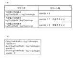
上記課題を解決するために、本発明に係る算術復号装置は、対象画像を単位領域毎に周波数変換することによって周波数成分毎に得られる変換係数について、該変換係数を表す各種シンタックスを算術符号化することによって得られた符号化データを復号する算術復号装置であって、処理対象の単位領域に対応する対象周波数領域を所定サイズのサブブロックに分割するサブブロック分割手段と、サブブロックのスキャン順を決定するスキャン順決定手段と、を備え、上記スキャン順決定手段は、上記単位領域の幅と高さに応じてスキャン順を決定することを特徴としている。 In order to solve the above problems, an arithmetic decoding apparatus according to the present invention uses arithmetic codes to express various syntaxes representing transform coefficients for transform coefficients obtained for each frequency component by subjecting a target image to frequency transform for each unit region. An arithmetic decoding apparatus for decoding encoded data obtained by converting into a sub-block dividing means for dividing a target frequency region corresponding to a unit region to be processed into sub-blocks of a predetermined size, and sub-block scanning Scan order determining means for determining the order, wherein the scan order determining means determines the scan order according to the width and height of the unit area.
上記の構成によれば、対象画像の周波数変換の単位領域であるTUの幅と高さに応じてサブブロックスキャン順を決定する。これにより、例えば、TUの幅と高さとが異なる場合に、非0係数の変換係数が出現しやすい領域を連続してスキャンすることにより、非0係数の変換係数が出現しやすい領域を連続して符号化でき、係数有無フラグの符号量を低減することができる。 According to the above configuration, the sub-block scan order is determined according to the width and height of the TU that is a unit region for frequency conversion of the target image. Thus, for example, when the width and height of the TU are different, by continuously scanning the region where the non-zero coefficient conversion coefficient is likely to appear, the region where the non-zero coefficient conversion coefficient is likely to appear is continuously detected. And the amount of code of the coefficient presence / absence flag can be reduced.
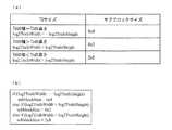
本発明に係る算術復号装置では、対象画像を単位領域毎に周波数変換することによって周波数成分毎に得られる変換係数について、該変換係数を表す各種シンタックスを算術符号化することによって得られた符号化データを復号する算術復号装置であって、処理対象の単位領域の幅と高さに応じてサブブロックのサイズを決定するサブブロックサイズ決定手段と、処理対象の単位領域に対応する対象周波数領域を、上記サブブロックサイズ決定手段が決定したサイズのサブブロックに分割するサブブロック分割手段と、を備えていてもよい。 In the arithmetic decoding device according to the present invention, codes obtained by arithmetically encoding various syntaxes representing transform coefficients for transform coefficients obtained for each frequency component by performing frequency transform on the target image for each unit region. An arithmetic decoding device for decoding encoded data, a sub-block size determining unit that determines a size of a sub-block according to a width and a height of a unit area to be processed, and a target frequency area corresponding to the unit area to be processed Sub-block dividing means for dividing the block into sub-blocks of the size determined by the sub-block size determining means.
上記の構成によれば、対象画像の周波数変換の単位領域であるTUの幅と高さに応じてサブブロックのサイズを決定する。よって、例えば、TUの幅と高さが異なる場合に、非0係数の変換係数が出現しやすい領域をカバーするようにサブブロックサイズを決定することにより、係数有無フラグの符号量を低減することができる。 According to said structure, the size of a subblock is determined according to the width | variety and height of TU which is a unit area | region of the frequency conversion of an object image. Therefore, for example, when the width and height of the TU are different, the code amount of the coefficient presence / absence flag is reduced by determining the sub-block size so as to cover a region where transform coefficients of non-zero coefficients are likely to appear. Can do.
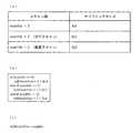
上記課題を解決するために、本発明に係る算術復号装置は、対象画像を単位領域毎に周波数変換することによって周波数成分毎に得られる変換係数について、該変換係数を表す各種シンタックスを算術符号化することによって得られた符号化データを復号する算術復号装置であって、スキャン順に応じてサブブロックサイズを決定するサブブロックサイズ決定手段と、処理対象の単位領域に対応する対象周波数領域を、、上記サブブロックサイズ決定手段が決定したサイズのサブブロックに分割するサブブロック分割手段と、を備えていることを特徴としている。 In order to solve the above problems, an arithmetic decoding apparatus according to the present invention uses arithmetic codes to express various syntaxes representing transform coefficients for transform coefficients obtained for each frequency component by subjecting a target image to frequency transform for each unit region. An arithmetic decoding device that decodes encoded data obtained by converting to a sub-block size determining unit that determines a sub-block size according to a scan order, and a target frequency region corresponding to a unit region to be processed, And sub-block dividing means for dividing the block into sub-blocks of the size determined by the sub-block size determining means.
上記の構成によれば、スキャン順が非0係数の変換係数が出現しやすい領域の偏りに沿っている場合において、その偏りにあわせた変換係数の領域をカバーするようにサブブロックサイズを決定することができる。これにより、係数有無フラグの符号量を低減することができる。 According to the above configuration, when the scan order is along the bias of the region where transform coefficients with non-zero coefficients tend to appear, the sub-block size is determined so as to cover the region of the transform coefficient according to the bias. be able to. Thereby, the code amount of the coefficient presence / absence flag can be reduced.
上記課題を解決するために、本発明に係る算術復号装置は、対象画像を単位領域毎に周波数変換することによって周波数成分毎に得られる変換係数について、該変換係数を表す各種シンタックスを算術符号化することによって得られた符号化データを復号する算術復号装置であって、処理対象の単位領域に対応する対象周波数領域を所定サイズのサブブロックに分割するサブブロック分割手段と、上記サブブロック分割手段により分割された各サブブロックについて、非0変換係数が少なくとも1つ含まれるか否かを表すサブブロック係数有無フラグを復号するサブブロック係数有無フラグ復号手段と、上記各サブブロック内の変換係数が0であるか否かを表す非0変換係数有無フラグを復号する非0変換係数有無フラグ復号手段と、を備え、上記非0変換係数有無フラグ復号手段は、対象変換係数の座標が低周波領域に存在する場合とサブブロック座標が高周波領域に存在する場合は、周波数領域上の位置に基づく値、または固定的な所定の値をコンテキストインデックスとして導出し、対象変換係数の座標が低周波領域に存在せず、かつサブブロック座標が高周波領域に存在しない場合の変換係数に対しては、復号済みの非0変換係数を参照することによってコンテキストインデックスを導出する特徴とすることを特徴としている。 In order to solve the above problems, an arithmetic decoding apparatus according to the present invention uses arithmetic codes to express various syntaxes representing transform coefficients for transform coefficients obtained for each frequency component by subjecting a target image to frequency transform for each unit region. An arithmetic decoding device that decodes encoded data obtained by converting into a sub-block dividing unit that divides a target frequency region corresponding to a unit region to be processed into sub-blocks of a predetermined size, and the sub-block division Subblock coefficient presence / absence flag decoding means for decoding a subblock coefficient presence / absence flag indicating whether or not at least one non-zero transform coefficient is included for each subblock divided by the means, and transform coefficients in each of the subblocks Non-zero transform coefficient presence / absence flag decoding means for decoding a non-zero transform coefficient presence / absence flag indicating whether or not is 0. The non-zero transform coefficient presence / absence flag decoding means, when the coordinates of the target transform coefficient are present in the low frequency region and when the sub-block coordinates are present in the high frequency region, the non-zero transform coefficient presence / absence flag decoding means Derived non-zero transform coefficient for a transform coefficient in which a predetermined value is derived as a context index and the coordinates of the target transform coefficient do not exist in the low frequency region and the sub-block coordinates do not exist in the high frequency region The feature is that the context index is derived by referring to.
上記の構成によれば、処理量の小さい位置コンテキストを多くの変換係数で用いることができる。これにより、コンテキストインデックスの導出に必要な処理量を低減することができる。 According to the above configuration, a position context with a small amount of processing can be used with many conversion coefficients. Thereby, the processing amount required for derivation of the context index can be reduced.
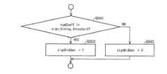
本発明に係る算術復号装置では、上記非0変換係数有無フラグ復号手段は、対象変換係数を含むサブブロック位置のX座標xCGとサブブロック位置のY座標yCGとの和が、上記単位領域の幅と高さの最大値から算出される閾値以上の場合に、当該サブブロックの座標が高周波領域に存在すると判定するものであってもよい。 In the arithmetic decoding device according to the present invention, the non-zero transform coefficient presence / absence flag decoding means is configured such that the sum of the X coordinate xCG of the sub-block position including the target transform coefficient and the Y coordinate yCG of the sub-block position is the width of the unit region. If the value is equal to or greater than the threshold calculated from the maximum value of the height, it may be determined that the coordinates of the sub-block exist in the high-frequency region.
上記の構成によれば、位置コンテキストを用いる変換係数の領域を適切に設定することができる。これにより、コンテキストインデックスの導出に必要な処理量と符号化効率性能のバランスを好適にすることができる。 According to said structure, the area | region of the conversion factor using a position context can be set appropriately. Thereby, the balance between the processing amount necessary for deriving the context index and the coding efficiency performance can be made suitable.
本発明に係る算術復号装置では、上記非0変換係数有無フラグ復号手段は、対象変換係数を含むサブブロック位置のX座標xCGとサブブロック位置のY座標yCGとの和が、上記単位領域の幅と高さの和から算出される閾値以上の場合に、当該サブブロックの座標が高周波領域に存在すると判定するものであってもよい。 In the arithmetic decoding device according to the present invention, the non-zero transform coefficient presence / absence flag decoding means is configured such that the sum of the X coordinate xCG of the sub-block position including the target transform coefficient and the Y coordinate yCG of the sub-block position is the width of the unit region. If the value is equal to or greater than the threshold calculated from the sum of the heights, the coordinates of the sub-block may be determined to exist in the high-frequency region.
上記の構成によれば、位置コンテキストを用いる変換係数の領域を適切に設定することができる。これにより、コンテキストインデックスの導出に必要な処理量と符号化効率性能のバランスを好適にすることができる。 According to said structure, the area | region of the conversion factor using a position context can be set appropriately. Thereby, the balance between the processing amount necessary for deriving the context index and the coding efficiency performance can be made suitable.
本発明に係る算術復号装置では、上記非0変換係数有無フラグ復号手段は、対象変換係数を含むサブブロック位置のX座標xCGとサブブロック位置のY座標yCGとの和が、上記単位領域の幅と高さの最小値から算出される閾値以上の場合に、当該サブブロックの座標が高周波領域に存在すると判定するものであってもよい。 In the arithmetic decoding device according to the present invention, the non-zero transform coefficient presence / absence flag decoding means is configured such that the sum of the X coordinate xCG of the sub-block position including the target transform coefficient and the Y coordinate yCG of the sub-block position is the width of the unit region. When the value is equal to or greater than the threshold value calculated from the minimum height value, it may be determined that the coordinates of the sub-block exist in the high-frequency region.
上記の構成によれば、位置コンテキストを用いる変換係数の領域を適切に設定することができる。これにより、コンテキストインデックスの導出に必要な処理量と符号化効率性能のバランスを好適にすることができる。 According to said structure, the area | region of the conversion factor using a position context can be set appropriately. Thereby, the balance between the processing amount necessary for deriving the context index and the coding efficiency performance can be made suitable.
本発明に係る算術復号装置では、上記非0変換係数有無フラグ復号手段は、上記単位領域の幅と高さが異なる場合に閾値を調整するものであってもよい。 In the arithmetic decoding apparatus according to the present invention, the non-zero transform coefficient presence / absence flag decoding means may adjust the threshold when the width and height of the unit area are different.
上記の構成によれば、位置コンテキストを用いる変換係数の領域をさらに適切に設定することができる。これにより、コンテキストインデックスの導出に必要な処理量と符号化効率性能のバランスをさらに好適にすることができる。 According to said structure, the area | region of the conversion factor using a position context can be set further appropriately. Thereby, it is possible to further improve the balance between the processing amount necessary for deriving the context index and the coding efficiency performance.
本発明に係る算術復号装置では、上記非0変換係数有無フラグ復号手段は、対象となるサブブロックの幅と高さが異なる場合に閾値を調整するものであってもよい。 In the arithmetic decoding apparatus according to the present invention, the non-zero transform coefficient presence / absence flag decoding means may adjust the threshold when the width and height of the target sub-block are different.
上記の構成によれば、位置コンテキストを用いる変換係数の領域をさらに適切に設定する。これにより、コンテキストインデックスの導出に必要な処理量と符号化効率性能のバランスをさらに好適にすることができる。 According to said structure, the area | region of the conversion factor using a position context is set more appropriately. Thereby, it is possible to further improve the balance between the processing amount necessary for deriving the context index and the coding efficiency performance.
上記課題を解決するために、本発明に係る算術復号装置は、対象画像を単位領域毎に周波数変換することによって周波数成分毎に得られる変換係数について、該変換係数を表す各種シンタックスを算術符号化することによって得られた符号化データを復号する算術復号装置であって、処理対象の単位領域に対応する対象周波数領域を所定サイズのサブブロックに分割するサブブロック分割手段と、上記サブブロック分割手段により分割された各サブブロックについて、非0変換係数が少なくとも1つ含まれるか否かを表すサブブロック係数有無フラグを復号するサブブロック係数有無フラグ復号手段と、上記各サブブロック内の変換係数が0であるか否かを表す非0変換係数有無フラグを復号する非0変換係数有無フラグ復号手段と、を備え、上記非0変換係数有無フラグ復号手段は、非0変換係数有無フラグの開始位置をサブブロック内のスキャン順におけるNの倍数(N=2、4、8、16)の位置に設定することを特徴としている。 In order to solve the above problems, an arithmetic decoding apparatus according to the present invention uses arithmetic codes to express various syntaxes representing transform coefficients for transform coefficients obtained for each frequency component by subjecting a target image to frequency transform for each unit region. An arithmetic decoding device that decodes encoded data obtained by converting into a sub-block dividing unit that divides a target frequency region corresponding to a unit region to be processed into sub-blocks of a predetermined size, and the sub-block division Subblock coefficient presence / absence flag decoding means for decoding a subblock coefficient presence / absence flag indicating whether or not at least one non-zero transform coefficient is included for each subblock divided by the means, and transform coefficients in each of the subblocks Non-zero transform coefficient presence / absence flag decoding means for decoding a non-zero transform coefficient presence / absence flag indicating whether or not is 0. The non-zero transform coefficient presence / absence flag decoding means sets the start position of the non-zero transform coefficient presence / absence flag to a position that is a multiple of N (N = 2, 4, 8, 16) in the scan order within the sub-block. It is said.
上記の構成によれば、係数有無フラグの導出方法が対象変換係数のサブブロック内の位置に応じて変化するような場合において、サブブロック内の係数有無フラグの導出方法の選択処理(テンプレートの選択)を、N回に1回行えば良いことになる。これにより、係数有無フラグの復号処理を簡略化することができる。 According to the above configuration, when the derivation method of the coefficient presence / absence flag changes depending on the position of the target transform coefficient in the sub-block, the selection process of the derivation method of the coefficient presence / absence flag in the sub-block (template selection) ) Should be performed once every N times. Thereby, the decoding process of the coefficient presence / absence flag can be simplified.
本発明に係る算術復号装置では、上記Nは16であってもよい。 In the arithmetic decoding apparatus according to the present invention, N may be 16.
上記の構成によれば、サブブロック内の係数有無フラグの導出方法の選択処理(テンプレートの選択)を省略することができる。これにより、係数有無フラグの復号処理を簡略化することができる。 According to the above configuration, the selection process (template selection) of the method for deriving the coefficient presence / absence flag in the sub-block can be omitted. Thereby, the decoding process of the coefficient presence / absence flag can be simplified.
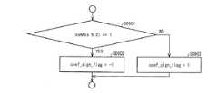
上記課題を解決するために、本発明に係る算術復号装置は、対象画像を単位領域毎に周波数変換することによって周波数成分毎に得られる変換係数について、該変換係数を表す各種シンタックスを算術符号化することによって得られた符号化データを復号する算術復号装置であって、サインハイディングを行う変換係数の符号は、変換係数の符号を既に復号した変換係数の絶対値もしくは既に復号した変換係数の絶対値の和を用いて導出し、サインハイディングを行わない変換係数の符号は、符号化データからシンタックスを復号する係数サイン復号手段と、サインハイディングを行うか否かの判定に用いるサインハイディングフラグを、対象サブブロック内で既に復号した非0の変換係数の位置の差、または、対象サブブロック内で既に既に復号した非0変換係数の数と所定の閾値との比較により導出するサインハイディングフラグ導出手段と、を備えていることを特徴としている。 In order to solve the above problems, an arithmetic decoding apparatus according to the present invention uses arithmetic codes to express various syntaxes representing transform coefficients for transform coefficients obtained for each frequency component by subjecting a target image to frequency transform for each unit region. An arithmetic decoding device that decodes encoded data obtained by converting to a sign of a transform coefficient that performs sign hiding is an absolute value of a transform coefficient that has already been decoded or a transform coefficient that has already been decoded. The sign of the transform coefficient that is derived using the sum of the absolute values of the two and is not subjected to sign hiding is used for coefficient sign decoding means for decoding the syntax from the encoded data, and for determining whether to perform sign hiding. The sign hiding flag is set to a difference in the position of a non-zero transform coefficient that has already been decoded in the target sub-block, or already in the target sub-block. It is characterized in that it comprises a a sign hiding flag deriving means for deriving a comparison of the number with a predetermined threshold value of the decoded non-zero transform coefficients.
上記の構成によれば、サインハイディングにより変換係数の符号の符号量を低減させることができる。これにより、符号化効率を向上させることができる。 According to said structure, the code amount of the code | symbol of a conversion coefficient can be reduced by sign hiding. Thereby, encoding efficiency can be improved.
本発明に係る算術復号装置では、上記サインハイディングフラグ導出手段は、対象変換係数を含むサブブロックの位置に応じて上記所定の閾値の値を変更するものであってもよい。 In the arithmetic decoding apparatus according to the present invention, the sign hiding flag deriving unit may change the value of the predetermined threshold according to the position of the sub-block including the target transform coefficient.
上記の構成によれば、主観画質に影響を与えやすい低周波数成分と、主観画質に影響を与えにくい高周波数成分とで、閾値を変更することができる。これにより、主観画質を低下させることなくサインハイディングの効果を向上させることができ、符号化効率を向上させることができる。 According to the above configuration, the threshold value can be changed between a low-frequency component that easily affects the subjective image quality and a high-frequency component that does not easily affect the subjective image quality. Thereby, the effect of sign hiding can be improved without reducing the subjective image quality, and the encoding efficiency can be improved.
本発明に係る算術復号装置では、上記、サインハイディングフラグ導出手段は、高周波領域における閾値として低周波領域における閾値以上の値を用いるものであってもよい。 In the arithmetic decoding apparatus according to the present invention, the sign hiding flag deriving unit may use a value equal to or higher than the threshold value in the low frequency region as the threshold value in the high frequency region.
上記の構成によれば、主観画質に影響を与えやすい低周波数成分よりも主観画質に影響を与えにくい高周波数成分の閾値を大きくする。これにより、主観画質を低下させることなくサインハイディングの効果を向上させることができ、符号化効率を向上させることができる。 According to the above configuration, the threshold value of the high frequency component that is less likely to affect the subjective image quality is made larger than the low frequency component that is likely to affect the subjective image quality. Thereby, the effect of sign hiding can be improved without reducing the subjective image quality, and the encoding efficiency can be improved.
本発明に係る算術復号装置では、上記サインハイディングフラグ導出手段は、対象サブブロック内で既に復号した非0変換係数の数が1個か否かにより、サインハイディングフラグを導出するものであってもよい。 In the arithmetic decoding apparatus according to the present invention, the sign hiding flag deriving means derives a sign hiding flag based on whether or not the number of non-zero transform coefficients already decoded in the target sub-block is one. May be.
上記の構成によれば、非0変換係数が1個の場合に変換係数の符号量を削減する効果が大きいことを利用でき、符号化効率を向上させることができる。 According to said structure, when there are one non-zero transform coefficient, it can utilize that the effect of reducing the code amount of a transform coefficient is large, and can improve encoding efficiency.
また、導出処理が容易な非0変換係数の数を用いてサインハイディングフラグを導出するため、非0の変換係数の位置の差を用いる場合に比べ、サインハイディングフラグの導出処理を簡略化することができる。 In addition, since the sign hiding flag is derived using the number of non-zero transform coefficients that are easy to derive, the derivation process of the sign hiding flag is simplified compared to the case where the difference in the position of the non-zero transform coefficient is used. can do.
本発明に係る算術復号装置では、上記係数サイン復号手段は、サインハイディングを行う対象となる変換係数の絶対値を用いて、上記サインハイディングを行う変換係数の符号を導出するものであってもよい。 In the arithmetic decoding device according to the present invention, the coefficient sine decoding means derives the sign of the transform coefficient to be subjected to the sign hiding using the absolute value of the transform coefficient to be subjected to the sign hiding. Also good.
上記の構成によれば、サブブロック内における変換係数の和absLevelの導出処理が不要になる。これにより、サインハイディングを行う場合の係数サイン導出処理を簡略化することができる。 According to said structure, the derivation | leading-out process of the sum absLevel of the transform coefficient in a subblock becomes unnecessary. As a result, the coefficient sine derivation process when sine hiding is performed can be simplified.
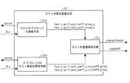
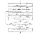
上記課題を解決するために、本発明に係る算術復号装置は、対象画像を単位領域毎に周波数変換することによって周波数成分毎に得られる変換係数について、該変換係数を表す各種シンタックスを算術符号化することによって得られた符号化データを復号する算術復号装置であって、処理対象の単位領域に対応する対象周波数領域を所定サイズのサブブロックに分割するサブブロック分割手段と、上記サブブロック分割手段により分割された各サブブロックについて、非0変換係数が少なくとも1つ含まれるか否かを表すサブブロック係数有無フラグを復号するサブブロック係数有無フラグ復号手段と、上記各サブブロック内の変換係数が0であるか否かを表す非0変換係数有無フラグを復号する非0変換係数有無フラグ復号手段と、上記サブブロック係数有無フラグと、上記非0変換係数有無フラグの復号の開始位置を示す情報とを、ラスト係数が位置するサブブロックの位置を表すラストサブブロック位置と、サブブロック内のラスト係数の位置を表すサブブロック内ラスト係数位置とから復号するラスト係数位置復号手段と、を備えていることを特徴としている。 In order to solve the above problems, an arithmetic decoding apparatus according to the present invention uses arithmetic codes to express various syntaxes representing transform coefficients for transform coefficients obtained for each frequency component by subjecting a target image to frequency transform for each unit region. An arithmetic decoding device that decodes encoded data obtained by converting into a sub-block dividing unit that divides a target frequency region corresponding to a unit region to be processed into sub-blocks of a predetermined size, and the sub-block division Subblock coefficient presence / absence flag decoding means for decoding a subblock coefficient presence / absence flag indicating whether or not at least one non-zero transform coefficient is included for each subblock divided by the means, and transform coefficients in each of the subblocks A non-zero transform coefficient presence / absence flag decoding means for decoding a non-zero transform coefficient presence / absence flag indicating whether or not is zero, The block coefficient presence / absence flag, the information indicating the decoding start position of the non-zero transform coefficient presence / absence flag, the last sub-block position indicating the position of the sub-block where the last coefficient is located, and the position of the last coefficient in the sub-block And a last coefficient position decoding means for decoding from the represented last coefficient position in the sub-block.
上記の構成によれば、ラスト位置の導出に必要なループをサブブロック毎に行うことができる。これにより、サブブロック係数有無フラグと係数有無フラグの復号の開始位置を示すラスト位置情報の導出処理を簡略化することができる。 According to said structure, the loop required for derivation | leading-out of a last position can be performed for every subblock. As a result, it is possible to simplify the process of deriving the last position information indicating the subblock coefficient presence / absence flag and the decoding start position of the coefficient presence / absence flag.
本発明に係る算術復号装置では、上記ラスト係数位置復号手段は、上記ラストサブブロック位置としてX座標とY座標とを復号し、上記サブブロック内ラスト係数位置としてX座標とY座標とを復号するものであってもよい。 In the arithmetic decoding device according to the present invention, the last coefficient position decoding means decodes the X coordinate and the Y coordinate as the last sub-block position, and decodes the X coordinate and the Y coordinate as the last sub-block last coefficient position. It may be a thing.
上記の構成によれば、ラストサブブロック位置及びサブブロック内ラスト係数位置をX座標とY座標とに分けて符号化する。これにより、ラスト位置情報を符号化するために必要な符号量を低減することができる。 According to the above configuration, the last sub-block position and the intra-sub-block last coefficient position are encoded separately in the X coordinate and the Y coordinate. Thereby, the amount of codes necessary for encoding the last position information can be reduced.
本発明に係る算術復号装置では、上記ラスト係数位置復号手段は、上記ラストサブブロック位置としてX座標とY座標とを復号し、上記サブブロック内ラスト係数位置としてサブブロック内のスキャン順を示す値を復号するものであってもよい。 In the arithmetic decoding device according to the present invention, the last coefficient position decoding means decodes the X coordinate and the Y coordinate as the last sub-block position, and a value indicating the scan order within the sub-block as the last coefficient position within the sub-block. May be decrypted.
上記の構成によれば、ラストサブブロック位置をX座標とY座標とに分けて符号化する。これにより、ラスト位置情報を符号化するために必要な符号量を低減することができる。また、ラスト位置の導出に必要なループをラストサブブロック位置についてのみ行えば良いため、ラスト位置情報の導出処理をさらに簡略化することができる。 According to the above configuration, the last sub-block position is encoded by being divided into the X coordinate and the Y coordinate. Thereby, the amount of codes necessary for encoding the last position information can be reduced. In addition, since the loop necessary for deriving the last position need only be performed for the last sub-block position, the deriving process of the last position information can be further simplified.
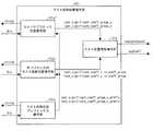
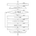
本発明に係る算術復号装置では、上記ラスト係数位置復号手段は、さらにラスト係数位置プリフィックスを復号し、ラスト係数位置プリフィックスが所定の値以下の場合には、ラスト係数位置プリフィックスからラストサブブロック位置と上記サブブロック内ラスト係数位置を導出し、ラスト係数位置プリフィックスが所定の値を超える場合には、上記ラストサブブロック位置と上記サブブロック内ラスト係数位置を復号するものであってもよい。 In the arithmetic decoding apparatus according to the present invention, the last coefficient position decoding means further decodes the last coefficient position prefix, and if the last coefficient position prefix is equal to or less than a predetermined value, the last coefficient position prefix and the last sub-block position are The intra-subblock last coefficient position may be derived, and when the last coefficient position prefix exceeds a predetermined value, the last subblock position and the intra-subblock last coefficient position may be decoded.
上記の構成によれば、ラスト係数位置プリフィックスを用いることにより、ラストサブブロック位置とサブブロック内ラスト係数位置の復号をスキップすることができる。これにより、ラスト位置情報を符号化するために必要な符号量を低減することができる。 According to said structure, decoding of the last subblock position and the last coefficient position in a subblock can be skipped by using the last coefficient position prefix. Thereby, the amount of codes necessary for encoding the last position information can be reduced.
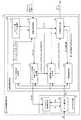
上記課題を解決するために、本発明に係る画像復号装置は、上記算術復号装置と、上記算術復号装置によって復号された変換係数を逆周波数変換することによって残差画像を生成する逆周波数変換手段と、上記逆周波数変換手段によって生成された残差画像と、生成済みの復号画像から予測された予測画像とを加算することによって復号画像を生成する復号画像生成手段と、を備えていることを特徴としている。 In order to solve the above problems, an image decoding apparatus according to the present invention includes the arithmetic decoding apparatus and an inverse frequency transforming unit that generates a residual image by performing inverse frequency transform on transform coefficients decoded by the arithmetic decoding apparatus. And a decoded image generating means for generating a decoded image by adding the residual image generated by the inverse frequency converting means and the predicted image predicted from the generated decoded image. It is a feature.
上記課題を解決するために、本発明に係る算術符号化装置は、対象画像を単位領域毎に周波数変換することによって周波数成分毎に得られる変換係数について、該変換係数を表す各種シンタックスを算術符号化することによって符号化データを生成する算術符号化装置であって、処理対象の単位領域に対応する対象周波数領域を所定サイズのサブブロックに分割するサブブロック分割手段と、上記サブブロック分割手段により分割された各サブブロックについて、非0変換係数が少なくとも1つ含まれるか否かを表すサブブロック係数有無フラグを符号化するサブブロック係数有無フラグ符号化手段と、上記各サブブロック内の変換係数が0であるか否かを表す非0変換係数有無フラグを符号化する非0変換係数有無フラグ符号化手段と、を備え、上記非0変換係数有無フラグ符号化手段は、ラスト係数を含むサブブロックの変換係数に対しては、周波数領域上の位置に基づく値、または固定的な所定の値をコンテキストインデックスとして用い、ラスト係数を含まないサブブロックの変換係数に対しては、符号化済みの非0変換係数を参照したコンテキストインデックスを用いることを特徴としている。 In order to solve the above-described problem, the arithmetic coding apparatus according to the present invention arithmetically expresses various syntaxes representing transform coefficients for transform coefficients obtained for each frequency component by performing frequency transform on the target image for each unit region. An arithmetic encoding device that generates encoded data by encoding, a sub-block dividing unit that divides a target frequency region corresponding to a unit region to be processed into sub-blocks of a predetermined size, and the sub-block dividing unit Sub-block coefficient presence / absence flag encoding means for encoding a sub-block coefficient presence / absence flag indicating whether or not at least one non-zero transform coefficient is included for each sub-block divided by Non-zero transform coefficient presence / absence flag encoding means for encoding a non-zero transform coefficient presence / absence flag indicating whether or not the coefficient is 0; The non-zero transform coefficient presence / absence flag encoding means uses a value based on a position in the frequency domain or a fixed predetermined value as a context index for a transform coefficient of a sub-block including a last coefficient, For transform coefficients of sub-blocks not including the last coefficient, a context index referring to an encoded non-zero transform coefficient is used.
上記課題を解決するために、本発明に係る画像符号化装置は、符号化対象画像と予測画像との残差画像を単位領域毎に周波数変換することによって変換係数を生成する変換係数生成手段と、上記算術符号化装置と、を備えており、上記算術符号化装置は、上記変換係数生成手段によって生成された変換係数を表す各種のシンタックスを算術符号化することによって符号化データを生成するものである、ことを特徴としている。 In order to solve the above problems, an image coding apparatus according to the present invention includes transform coefficient generation means for generating a transform coefficient by frequency-converting a residual image between an encoding target image and a predicted image for each unit region. The arithmetic encoding device, and the arithmetic encoding device generates encoded data by arithmetically encoding various syntaxes representing transform coefficients generated by the transform coefficient generating means. It is characterized by being.
以上のように、本発明に係る算術復号装置は、処理対象の単位領域に対応する対象周波数領域を所定サイズのサブブロックに分割するサブブロック分割手段と、上記サブブロック分割手段により分割された各サブブロックについて、非0変換係数が少なくとも1つ含まれるか否かを表すサブブロック係数有無フラグを復号するサブブロック係数有無フラグ復号手段と、上記各サブブロック内の変換係数が0であるか否かを表す非0変換係数有無フラグを復号する非0変換係数有無フラグ復号手段と、を備え、上記非0変換係数有無フラグ復号手段は、ラスト係数を含むサブブロックの変換係数に対しては、周波数領域上の位置に基づく値、または固定的な所定の値をコンテキストインデックスとして導出し、ラスト係数を含まないサブブロックの変換係数に対しては、復号済みの非0変換係数を参照することによってコンテキストインデックスを導出する構成である。 As described above, the arithmetic decoding apparatus according to the present invention includes a sub-block dividing unit that divides a target frequency region corresponding to a unit region to be processed into sub-blocks of a predetermined size, and each of the sub-block dividing units divided by the sub-block dividing unit. Subblock coefficient presence / absence flag decoding means for decoding a subblock coefficient presence / absence flag indicating whether or not at least one non-zero transform coefficient is included for a subblock, and whether or not the transform coefficient in each subblock is 0 Non-zero transform coefficient presence / absence flag decoding means for decoding the non-zero transform coefficient presence / absence flag representing the non-zero transform coefficient presence / absence flag decoding means for the transform coefficient of the sub-block including the last coefficient, A value based on the position in the frequency domain or a fixed predetermined value is derived as a context index, and a sub-block that does not include the last coefficient is derived. For the transformation coefficient, it is configured to derive a context index by referring to the non-zero transform coefficients decoded.
これにより、復号済みの非0変換係数を参照する場合に必要なサブブロック内の係数有無フラグの導出方法の選択処理(テンプレートの選択)を省略することができ、係数有無フラグの復号処理を簡略化することができるという効果を奏する。 As a result, the selection process (template selection) of the method for deriving the coefficient presence / absence flag in the sub-block necessary when referring to the decoded non-zero transform coefficient can be omitted, and the coefficient presence / absence flag decoding process is simplified. There is an effect that can be made.
本発明に係る復号装置および符号化装置の実施形態について図面に基づいて説明すれば以下のとおりである。なお、本実施形態に係る復号装置は、符号化データから動画像を復号するものである。したがって、以下では、これを「動画像復号装置」と呼称する。また、本実施形態に係る符号化装置は、動画像を符号化することによって符号化データを生成するものである。したがって、以下では、これを「動画像符号化装置」と呼称する。 Embodiments of a decoding apparatus and an encoding apparatus according to the present invention will be described below with reference to the drawings. Note that the decoding apparatus according to the present embodiment decodes a moving image from encoded data. Therefore, hereinafter, this is referred to as “moving image decoding apparatus”. In addition, the encoding device according to the present embodiment generates encoded data by encoding a moving image. Therefore, hereinafter, this is referred to as a “moving image encoding device”.
ただし、本発明の適用範囲はこれに限定されるものではない。すなわち、以下の説明からも明らかなように、本発明の特徴は複数のフレームを前提としなくとも成立するものである。すなわち、動画像を対象とするか静止画像を対象とするかを問わず、復号装置一般および符号化装置一般に適用できるものである。 However, the scope of application of the present invention is not limited to this. That is, as will be apparent from the following description, the features of the present invention can be realized without assuming a plurality of frames. That is, the present invention can be applied to a general decoding apparatus and a general encoding apparatus regardless of whether the target is a moving image or a still image.
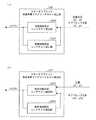
(符号化データ#1の構成)
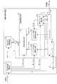
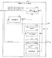
図2を用いて、動画像符号化装置2によって生成され、動画像復号装置1によって復号される符号化データ#1の構成例について説明する。符号化データ#1は、例示的に、シーケンス、およびシーケンスを構成する複数のピクチャを含む。(Configuration of encoded data # 1)
A configuration example of encoded
シーケンスレイヤでは、処理対象のシーケンスを復号するために、動画像復号装置1が参照するデータの集合が規定されている。シーケンスレイヤにはシーケンスパラメータセットSPS、ピクチャパラメータセットPPS、ピクチャPICTを含んでいる。 In the sequence layer, a set of data referred to by the
符号化データ#1におけるピクチャレイヤ以下の階層の構造を図2に示す。図2の(a)〜(d)は、それぞれ、ピクチャPICTを規定するピクチャレイヤ、スライスSを規定するスライスレイヤ、ツリーブロック(Tree block)TBLKを規定するツリーブロックレイヤ、ツリーブロックTBLKに含まれる符号化単位(Coding Unit;CU)を規定するCUレイヤを示す図である。 FIG. 2 shows a hierarchical structure below the picture layer in the encoded
(ピクチャレイヤ)
ピクチャレイヤでは、処理対象のピクチャPICT(以下、対象ピクチャとも称する)を復号するために動画像復号装置1が参照するデータの集合が規定されている。ピクチャPICTは、図2の(a)に示すように、ピクチャヘッダPH、及び、スライスS1〜SNSを含んでいる(NSはピクチャPICTに含まれるスライスの総数)。(Picture layer)
In the picture layer, a set of data referred to by the
なお、以下、スライスS1〜SNSのそれぞれを区別する必要が無い場合、符号の添え字を省略して記述することがある。また、以下に説明する符号化データ#1に含まれるデータであって、添え字を付している他のデータについても同様である。 Hereinafter, when it is not necessary to distinguish each of the slices S1 to SNS, the subscripts may be omitted. The same applies to other data with subscripts included in encoded
ピクチャヘッダPHには、対象ピクチャの復号方法を決定するために動画像復号装置1が参照する符号化パラメータ群が含まれている。 The picture header PH includes a coding parameter group that is referred to by the
(スライスレイヤ)
スライスレイヤでは、処理対象のスライスS(対象スライスとも称する)を復号するために動画像復号装置1が参照するデータの集合が規定されている。スライスSは、図2の(b)に示すように、スライスヘッダSH、及び、ツリーブロックTBLK1〜TBLKNC(NCはスライスSに含まれるツリーブロックの総数)を含んでいる。(Slice layer)
In the slice layer, a set of data referred to by the
スライスヘッダSHには、対象スライスの復号方法を決定するために動画像復号装置1が参照する符号化パラメータ群が含まれる。スライスタイプを指定するスライスタイプ指定情報(slice_type)は、スライスヘッダSHに含まれる符号化パラメータの一例である。 The slice header SH includes an encoding parameter group that is referred to by the
スライスタイプ指定情報により指定可能なスライスタイプとしては、(1)符号化の際にイントラ予測のみを用いるIスライス、(2)符号化の際に単予測、又は、イントラ予測を用いるPスライス、(3)符号化の際に単予測、双予測、又は、イントラ予測を用いるBスライスなどが挙げられる。 The slice types that can be specified by the slice type specification information include (1) I slice that uses only intra prediction at the time of encoding, (2) P slice that uses single prediction or intra prediction at the time of encoding, ( 3) B-slice using single prediction, bi-prediction, or intra prediction at the time of encoding may be used.
また、スライスヘッダSHには、動画像復号装置1の備えるループフィルタによって参照されるフィルタパラメータFPが含まれている。フィルタパラメータFPは、フィルタ係数群を含んでいる。フィルタ係数群には、(1)フィルタのタップ数を指定するタップ数指定情報、(2)フィルタ係数a0〜aNT-1(NTは、フィルタ係数群に含まれるフィルタ係数の総数)、および、(3)オフセットが含まれる。 In addition, the slice header SH includes a filter parameter FP that is referred to by a loop filter included in the
(ツリーブロックレイヤ)
ツリーブロックレイヤでは、処理対象のツリーブロックTBLK(以下、対象ツリーブロックとも称する)を復号するために動画像復号装置1が参照するデータの集合が規定されている。(Tree block layer)
In the tree block layer, a set of data referred to by the
ツリーブロックTBLKは、ツリーブロックヘッダTBLKHと、符号化単位情報CU1〜CUNL(NLはツリーブロックTBLKに含まれる符号化単位情報の総数)とを含む。ここで、まず、ツリーブロックTBLKと、符号化単位情報CUとの関係について説明すると次のとおりである。 The tree block TBLK includes a tree block header TBLKH and coding unit information CU1 to CUNL (NL is the total number of coding unit information included in the tree block TBLK). Here, first, a relationship between the tree block TBLK and the coding unit information CU will be described as follows.
ツリーブロックTBLKは、イントラ予測またはインター予測、および、変換の各処理ためのブロックサイズを特定するためのユニットに分割される。 Tree block TBLK is divided into units for specifying a block size for each process of intra prediction or inter prediction and transformation.
ツリーブロックTBLKの上記ユニットは、再帰的な4分木分割により分割されている。この再帰的な4分木分割により得られる木構造のことを以下、符号化ツリー(coding tree)と称する。 The unit of the tree block TBLK is divided by recursive quadtree division. The tree structure obtained by this recursive quadtree partitioning is hereinafter referred to as a coding tree.
以下、符号化ツリーの末端のノードであるリーフ(leaf)に対応するユニットを、符号化ノード(coding node)として参照する。また、符号化ノードは、符号化処理の基本的な単位となるため、以下、符号化ノードのことを、符号化単位(CU)とも称する。 Hereinafter, a unit corresponding to a leaf which is a node at the end of the coding tree is referred to as a coding node. In addition, since the encoding node is a basic unit of the encoding process, hereinafter, the encoding node is also referred to as an encoding unit (CU).
つまり、符号化単位情報CU1〜CUNLは、ツリーブロックTBLKを再帰的に4分木分割して得られる各符号化ノード(符号化単位)に対応する情報である。 That is, the coding unit information CU1 to CUNL is information corresponding to each coding node (coding unit) obtained by recursively dividing the tree block TBLK into quadtrees.
また、符号化ツリーのルート(root)は、ツリーブロックTBLKに対応付けられる。換言すれば、ツリーブロックTBLKは、複数の符号化ノードを再帰的に含む4分木分割の木構造の最上位ノードに対応付けられる。 Also, the root of the coding tree is associated with the tree block TBLK. In other words, the tree block TBLK is associated with the highest node of the tree structure of the quadtree partition that recursively includes a plurality of encoding nodes.
なお、各符号化ノードのサイズは、当該符号化ノードが直接に属する符号化ノード(すなわち、当該符号化ノードの1階層上位のノードのユニット)のサイズの縦横とも半分である。 Note that the size of each coding node is half of the size of the coding node to which the coding node directly belongs (that is, the unit of the node one level higher than the coding node).
また、各符号化ノードの取り得るサイズは、符号化データ#1のシーケンスパラメータセットSPSに含まれる、符号化ノードのサイズ指定情報および最大階層深度(maximum hierarchical depth)に依存する。例えば、ツリーブロックTBLKのサイズが64×64画素であって、最大階層深度が3である場合には、当該ツリーブロックTBLK以下の階層における符号化ノードは、4種類のサイズ、すなわち、64×64画素、32×32画素、16×16画素、および8×8画素の何れかを取り得る。 In addition, the size that each coding node can take depends on the size designation information and the maximum hierarchical depth of the coding node included in the sequence parameter set SPS of the coded
(ツリーブロックヘッダ)
ツリーブロックヘッダTBLKHには、対象ツリーブロックの復号方法を決定するために動画像復号装置1が参照する符号化パラメータが含まれる。具体的には、図2の(c)に示すように、対象ツリーブロックの各CUへの分割パターンを指定するツリーブロック分割情報SP_TBLK、および、量子化ステップの大きさを指定する量子化パラメータ差分Δqp(qp_delta)が含まれる。(Tree block header)
The tree block header TBLKH includes an encoding parameter referred to by the
ツリーブロック分割情報SP_TBLKは、ツリーブロックを分割するための符号化ツリーを表す情報であり、具体的には、対象ツリーブロックに含まれる各CUの形状、サイズ、および、対象ツリーブロック内での位置を指定する情報である。 The tree block division information SP_TBLK is information representing a coding tree for dividing the tree block. Specifically, the shape and size of each CU included in the target tree block, and the position in the target tree block Is information to specify.
なお、ツリーブロック分割情報SP_TBLKは、CUの形状やサイズを明示的に含んでいなくてもよい。例えばツリーブロック分割情報SP_TBLKは、対象ツリーブロック全体またはツリーブロックの部分領域を四分割するか否かを示すフラグ(split_coding_unit_flag)の集合であってもよい。その場合、ツリーブロックの形状やサイズを併用することで各CUの形状やサイズを特定できる。 Note that the tree block division information SP_TBLK may not explicitly include the shape or size of the CU. For example, the tree block division information SP_TBLK may be a set of flags (split_coding_unit_flag) indicating whether or not the entire target tree block or a partial area of the tree block is divided into four. In that case, the shape and size of each CU can be specified by using the shape and size of the tree block together.
また、量子化パラメータ差分Δqpは、対象ツリーブロックにおける量子化パラメータqpと、当該対象ツリーブロックの直前に符号化されたツリーブロックにおける量子化パラメータqp’との差分qp−qp’である。 The quantization parameter difference Δqp is a difference qp−qp ′ between the quantization parameter qp in the target tree block and the quantization parameter qp ′ in the tree block encoded immediately before the target tree block.
(CUレイヤ)
CUレイヤでは、処理対象のCU(以下、対象CUとも称する)を復号するために動画像復号装置1が参照するデータの集合が規定されている。(CU layer)
In the CU layer, a set of data referred to by the
ここで、符号化単位情報CUに含まれるデータの具体的な内容の説明をする前に、CUに含まれるデータの木構造について説明する。符号化ノードは、予測ツリー(prediction tree;PT)および変換ツリー(transform tree;TT)のルートのノードとなる。予測ツリーおよび変換ツリーについて説明すると次のとおりである。 Here, before describing specific contents of data included in the coding unit information CU, a tree structure of data included in the CU will be described. The encoding node is a node at the root of a prediction tree (PT) and a transform tree (TT). The prediction tree and the conversion tree are described as follows.
予測ツリーにおいては、符号化ノードが1または複数の予測ブロックに分割され、各予測ブロックの位置とサイズとが規定される。別の表現でいえば、予測ブロックは、符号化ノードを構成する1または複数の重複しない領域である。また、予測ツリーは、上述の分割により得られた1または複数の予測ブロックを含む。 In the prediction tree, the encoding node is divided into one or a plurality of prediction blocks, and the position and size of each prediction block are defined. In other words, the prediction block is one or a plurality of non-overlapping areas constituting the encoding node. The prediction tree includes one or a plurality of prediction blocks obtained by the above division.
予測処理は、この予測ブロックごとに行われる。以下、予測の単位である予測ブロックのことを、予測単位(prediction unit;PU)とも称する。 Prediction processing is performed for each prediction block. Hereinafter, a prediction block that is a unit of prediction is also referred to as a prediction unit (PU).
予測ツリーにおける分割の種類は、大まかにいえば、イントラ予測の場合と、インター予測の場合との2つがある。 Broadly speaking, there are two types of division in the prediction tree: intra prediction and inter prediction.
イントラ予測の場合、分割方法は、2N×2N(符号化ノードと同一サイズ)と、N×Nとがある。 In the case of intra prediction, there are 2N × 2N (the same size as the encoding node) and N × N division methods.
また、インター予測の場合、分割方法は、2N×2N(符号化ノードと同一サイズ)、2N×N、N×2N、および、N×Nなどがある。 In the case of inter prediction, there are 2N × 2N (the same size as the encoding node), 2N × N, N × 2N, N × N, and the like.
また、変換ツリーにおいては、符号化ノードが1または複数の変換ブロックに分割され、各変換ブロックの位置とサイズとが規定される。別の表現でいえば、変換ブロックは、符号化ノードを構成する1または複数の重複しない領域のことである。また、変換ツリーは、上述の分割より得られた1または複数の変換ブロックを含む。 In the transform tree, the encoding node is divided into one or a plurality of transform blocks, and the position and size of each transform block are defined. In other words, the transform block is one or a plurality of non-overlapping areas constituting the encoding node. The conversion tree includes one or a plurality of conversion blocks obtained by the above division.
変換処理は、この変換ブロックごとに行われる。以下、変換の単位である変換ブロックのことを、変換単位(transform unit;TU)とも称する。TUのサイズは、変換ブロックの横幅と対数log2TrafoWidthと縦幅の対数値log2TrafoHeightで表される。TUのサイズはまた、以下の式で得られる値log2TrafoSizeでも表される。 The conversion process is performed for each conversion block. Hereinafter, a transform block that is a unit of transform is also referred to as a transform unit (TU). The size of the TU is represented by the horizontal width and logarithm log2TrafoWidth of the transform block and the logarithmic value log2TrafoHeight of the vertical width. The size of the TU is also represented by a value log2TrafoSize obtained by the following equation.
log2TrafoSize = ( log2TrafoWidth + log2TrafoHeight ) >> 1
以下、横幅W×縦幅Hのサイズを有するTUをW×HTUと呼ぶ(例:4×4TU)。log2TrafoSize = (log2TrafoWidth + log2TrafoHeight) >> 1
Hereinafter, a TU having a size of horizontal width W × longitudinal width H is referred to as W × HTU (example: 4 × 4 TU).
(符号化単位情報のデータ構造)
続いて、図2の(d)を参照しながら符号化単位情報CUに含まれるデータの具体的な内容について説明する。図2の(d)に示すように、符号化単位情報CUは、具体的には、スキップモードフラグSKIP、CU予測タイプ情報Pred_type、PT情報PTI、および、TT情報TTIを含む。(Data structure of encoding unit information)
Next, specific contents of data included in the coding unit information CU will be described with reference to FIG. As shown in FIG. 2D, the coding unit information CU specifically includes a skip mode flag SKIP, CU prediction type information Pred_type, PT information PTI, and TT information TTI.
[スキップフラグ]
スキップフラグSKIPは、対象CUについて、スキップモードが適用されているか否かを示すフラグであり、スキップフラグSKIPの値が1の場合、すなわち、対象CUにスキップモードが適用されている場合、その符号化単位情報CUにおけるPT情報PTIは省略される。なお、スキップフラグSKIPは、Iスライスでは省略される。[Skip flag]
The skip flag SKIP is a flag indicating whether or not the skip mode is applied to the target CU. When the value of the skip flag SKIP is 1, that is, when the skip mode is applied to the target CU, the code The PT information PTI in the unit information CU is omitted. Note that the skip flag SKIP is omitted for the I slice.
[CU予測タイプ情報]
CU予測タイプ情報Pred_typeは、CU予測方式情報PredModeおよびPU分割タイプ情報PartModeを含む。CU予測タイプ情報のことを単に予測タイプ情報と呼ぶこともある。[CU prediction type information]
The CU prediction type information Pred_type includes CU prediction method information PredMode and PU partition type information PartMode. The CU prediction type information may be simply referred to as prediction type information.
CU予測方式情報PredModeは、対象CUに含まれる各PUについての予測画像生成方法として、イントラ予測(イントラCU)、および、インター予測(インターCU)のいずれを用いるのかを指定するものである。なお、以下では、対象CUにおける、スキップ、イントラ予測、および、インター予測の種別を、CU予測モードと称する。 The CU prediction method information PredMode specifies whether intra prediction (intra CU) or inter prediction (inter CU) is used as a predicted image generation method for each PU included in the target CU. Hereinafter, the types of skip, intra prediction, and inter prediction in the target CU are referred to as a CU prediction mode.
PU分割タイプ情報PartModeは、対象符号化単位(CU)の各PUへの分割のパターンであるPU分割タイプを指定するものである。以下、このように、PU分割タイプに従って、対象符号化単位(CU)を各PUへ分割することをPU分割と称する。 The PU partition type information PartMode designates a PU partition type that is a pattern of partitioning the target coding unit (CU) into each PU. Hereinafter, dividing the target coding unit (CU) into each PU according to the PU division type in this way is referred to as PU division.
PU分割タイプ情報PartModeは、例示的には、PU分割パターンの種類を示すインデックスであってもよいし、対象予測ツリーに含まれる各PUの形状、サイズ、および、対象予測ツリー内での位置が指定されていてもよい。 For example, the PU partition type information PartMode may be an index indicating the type of PU partition pattern, and the shape, size, and position of each PU included in the target prediction tree may be It may be specified.
なお、選択可能なPU分割タイプは、CU予測方式とCUサイズに応じて異なる。また、さらにいえば、選択可能なPU分割タイプは、インター予測およびイントラ予測それぞれの場合において異なる。また、PU分割タイプの詳細については後述する。 The selectable PU partition types differ depending on the CU prediction method and the CU size. Furthermore, the PU partition types that can be selected differ in each case of inter prediction and intra prediction. Details of the PU partition type will be described later.
[PT情報]
PT情報PTIは、対象CUに含まれるPTに関する情報である。言い換えれば、PT情報PTIは、PTに含まれる1または複数のPUそれぞれに関する情報の集合である。上述のとおり予測画像の生成は、PUを単位として行われるので、PT情報PTIは、動画像復号装置1によって予測画像が生成される際に参照される。PT情報PTIは、図2の(d)に示すように、各PUにおける予測情報等を含むPU情報PUI1〜PUINP(NPは、対象PTに含まれるPUの総数)を含む。[PT information]
The PT information PTI is information related to the PT included in the target CU. In other words, the PT information PTI is a set of information on each of one or more PUs included in the PT. As described above, since the generation of the predicted image is performed in units of PUs, the PT information PTI is referred to when the moving
予測情報PUIは、予測タイプ情報Pred_modeが何れの予測方法を指定するのかに応じて、イントラ予測パラメータPP_Intra、または、インター予測パラメータPP_Interを含む。以下では、イントラ予測が適用されるPUをイントラPUとも呼称し、インター予測が適用されるPUをインターPUとも呼称する。 The prediction information PUI includes an intra prediction parameter PP_Intra or an inter prediction parameter PP_Inter depending on which prediction method is specified by the prediction type information Pred_mode. Hereinafter, a PU to which intra prediction is applied is also referred to as an intra PU, and a PU to which inter prediction is applied is also referred to as an inter PU.
インター予測パラメータPP_Interは、動画像復号装置1が、インター予測によってインター予測画像を生成する際に参照される符号化パラメータを含む。 The inter prediction parameter PP_Inter includes a coding parameter referred to when the
インター予測パラメータPP_Interとしては、例えば、マージフラグ(merge_flag)、マージインデックス(merge_idx)、推定動きベクトルインデックス(mvp_idx)、参照画像インデックス(ref_idx)、インター予測フラグ(inter_pred_flag)、および動きベクトル残差(mvd)が挙げられる。 Examples of the inter prediction parameter PP_Inter include a merge flag (merge_flag), a merge index (merge_idx), an estimated motion vector index (mvp_idx), a reference image index (ref_idx), an inter prediction flag (inter_pred_flag), and a motion vector residual (mvd). ).
イントラ予測パラメータPP_Intraは、動画像復号装置1が、イントラ予測によってイントラ予測画像を生成する際に参照される符号化パラメータを含む。 The intra prediction parameter PP_Intra includes a coding parameter that is referred to when the
イントラ予測パラメータPP_Intraとしては、例えば、推定予測モードフラグ、推定予測モードインデックス、および、残余予測モードインデックスが挙げられる。 Examples of the intra prediction parameter PP_Intra include an estimated prediction mode flag, an estimated prediction mode index, and a residual prediction mode index.
なお、イントラ予測パラメータには、PCMモードを用いるか否かを示すPCMモードフラグが含まれていてもよい。PCMモードフラグが符号化されている場合であって、PCMモードフラグがPCMモードを用いることを示しているときには、予測処理(イントラ)、変換処理、および、エントロピー符号化の各処理が省略される。 The intra prediction parameter may include a PCM mode flag indicating whether to use the PCM mode. When the PCM mode flag is encoded and the PCM mode flag indicates that the PCM mode is used, the prediction process (intra), the conversion process, and the entropy encoding process are omitted. .
[TT情報]
TT情報TTIは、CUに含まれるTTに関する情報である。言い換えれば、TT情報TTIは、TTに含まれる1または複数のTUそれぞれに関する情報の集合であり、動画像復号装置1により残差データを復号する際に参照される。なお、以下、TUのことをブロックと称することもある。[TT information]
The TT information TTI is information regarding the TT included in the CU. In other words, the TT information TTI is a set of information regarding each of one or a plurality of TUs included in the TT, and is referred to when the moving
TT情報TTIは、図2の(d)に示すように、対象CUの各変換ブロックへの分割パターンを指定するTT分割情報SP_TU、および、TU情報TUI1〜TUINT(NTは、対象CUに含まれるブロックの総数)を含んでいる。 As shown in FIG. 2D, the TT information TTI includes TT division information SP_TU that designates a division pattern of the target CU into each transform block, and TU information TUI1 to TUINT (NT is included in the target CU. The total number of blocks).
TT分割情報SP_TUは、具体的には、対象CUに含まれる各TUの形状、サイズ、および、対象CU内での位置を決定するための情報である。例えば、TT分割情報SP_TUは、対象となるノードの分割を行うのか否かを示す情報(split_transform_flag)と、その分割の深度を示す情報(trafoDepth)とから実現することができる。 Specifically, the TT division information SP_TU is information for determining the shape and size of each TU included in the target CU and the position within the target CU. For example, the TT division information SP_TU can be realized from information (split_transform_flag) indicating whether or not the target node is to be divided and information (trafoDepth) indicating the depth of the division.
また、例えば、CUのサイズが、64×64の場合、分割により得られる各TUは、32×32画素から4×4画素までのサイズを取り得る。 For example, when the size of the CU is 64 × 64, each TU obtained by the division can take a size from 32 × 32 pixels to 4 × 4 pixels.
TU情報TUI1〜TUINTは、TTに含まれる1または複数のTUそれぞれに関する個別の情報である。例えば、TU情報TUIは、量子化予測残差(量子化残差とも呼ぶ)を含んでいる。 The TU information TUI1 to TUINT is individual information regarding each of one or more TUs included in the TT. For example, the TU information TUI includes a quantized prediction residual (also referred to as a quantized residual).
各量子化予測残差は、動画像符号化装置2が以下の処理1〜3を、処理対象のブロックである対象ブロックに施すことによって生成した符号化データである。 Each quantization prediction residual is encoded data generated by the moving
処理1:符号化対象画像から予測画像を減算した予測残差を周波数変換(例えばDCT変換(Discrete Cosine Transform))する;
処理2:処理1にて得られた変換係数を量子化する;
処理3:処理2にて量子化された変換係数を可変長符号化する;
なお、上述した量子化パラメータqpは、動画像符号化装置2が変換係数を量子化する際に用いた量子化ステップQPの大きさを表す(QP=2qp/6)。Process 1: Frequency conversion (for example, DCT transform (Discrete Cosine Transform)) of the prediction residual obtained by subtracting the prediction image from the encoding target image;
Process 2: Quantize the transform coefficient obtained in
Process 3: Variable length coding is performed on the transform coefficient quantized in
The quantization parameter qp described above represents the magnitude of the quantization step QP used when the moving
(PU分割タイプ)
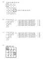
PU分割タイプには、対象CUのサイズを2N×2N画素とすると、次の合計8種類のパターンがある。すなわち、2N×2N画素、2N×N画素、N×2N画素、およびN×N画素の4つの対称的分割(symmetric splittings)、並びに、2N×nU画素、2N×nD画素、nL×2N画素、およびnR×2N画素の4つの非対称的分割(asymmetric splittings)である。なお、N=2m(mは1以上の任意の整数)を意味している。以下、対称CUを分割して得られる領域のことをパーティションとも称する。(PU split type)
In the PU division type, if the size of the target CU is 2N × 2N pixels, there are the following eight patterns in total. That is, 4 symmetric splittings of 2N × 2N pixels, 2N × N pixels, N × 2N pixels, and N × N pixels, and 2N × nU pixels, 2N × nD pixels, nL × 2N pixels, And four asymmetric splittings of nR × 2N pixels. Note that N = 2m (m is an arbitrary integer of 1 or more). Hereinafter, an area obtained by dividing a symmetric CU is also referred to as a partition.
図3の(a)〜(h)に、それぞれの分割タイプについて、CUにおけるPU分割の境界の位置を具体的に図示している。 3A to 3H specifically show the positions of the boundaries of PU division in the CU for each division type.
図3の(a)は、CUの分割を行わない2N×2NのPU分割タイプを示している。また、図3の(b)、(c)、および(d)は、それぞれ、PU分割タイプが、2N×N、2N×nU、および、2N×nDである場合のパーティションの形状について示している。また、図3の(e)、(f)、および(g)は、それぞれ、PU分割タイプが、N×2N、nL×2N、および、nR×2Nである場合のパーティションの形状について示している。また、図3の(h)は、PU分割タイプが、N×Nである場合のパーティションの形状を示している。 FIG. 3A illustrates a 2N × 2N PU partition type that does not perform CU partitioning. Moreover, (b), (c), and (d) of FIG. 3 show the shapes of partitions when the PU partition types are 2N × N, 2N × nU, and 2N × nD, respectively. . Also, (e), (f), and (g) of FIG. 3 show the shapes of the partitions when the PU partition types are N × 2N, nL × 2N, and nR × 2N, respectively. . Moreover, (h) of FIG. 3 has shown the shape of the partition in case PU partition type is NxN.
図3の(a)および(h)のPU分割タイプのことを、そのパーティションの形状に基づいて、正方形分割とも称する。また、図3の(b)〜(g)のPU分割タイプのことは、非正方形分割とも称する。 The PU partition types shown in FIGS. 3A and 3H are also referred to as square partitioning based on the shape of the partition. Further, the PU partition types shown in FIGS. 3B to 3G are also referred to as non-square partitions.
また、図3の(a)〜(h)において、各領域に付した番号は、領域の識別番号を示しており、この識別番号順に、領域に対して処理が行われる。すなわち、当該識別番号は、領域のスキャン順を表している。 In FIGS. 3A to 3H, the numbers assigned to the respective regions indicate the region identification numbers, and the regions are processed in the order of the identification numbers. That is, the identification number represents the scan order of the area.
[インター予測の場合の分割タイプ]
インターPUでは、上記8種類の分割タイプのうち、N×N(図3の(h))以外の7種類が定義されている。なお、上記6つの非対称的分割は、AMP(Asymmetric Motion Partition)と呼ばれることもある。[Partition type for inter prediction]
In the inter PU, seven types other than N × N ((h) in FIG. 3) are defined among the above eight division types. The six asymmetric partitions are sometimes called AMP (Asymmetric Motion Partition).
また、Nの具体的な値は、当該PUが属するCUのサイズによって規定され、nU、nD、nL、および、nRの具体的な値は、Nの値に応じて定められる。例えば、128×128画素のインターCUは、128×128画素、128×64画素、64×128画素、64×64画素、128×32画素、128×96画素、32×128画素、および、96×128画素のインターPUへ分割することが可能である。 A specific value of N is defined by the size of the CU to which the PU belongs, and specific values of nU, nD, nL, and nR are determined according to the value of N. For example, a 128 × 128 pixel inter-CU includes 128 × 128 pixels, 128 × 64 pixels, 64 × 128 pixels, 64 × 64 pixels, 128 × 32 pixels, 128 × 96 pixels, 32 × 128 pixels, and 96 × It is possible to divide into 128-pixel inter PUs.
[イントラ予測の場合の分割タイプ]
イントラPUでは、次の2種類の分割パターンが定義されている。対象CUを分割しない、すなわち対象CU自身が1つのPUとして取り扱われる分割パターン2N×2Nと、対象CUを、4つのPUへと対称的に分割するパターンN×Nと、である。[Partition type for intra prediction]
In the intra PU, the following two types of division patterns are defined. A division pattern 2N × 2N in which the target CU is not divided, that is, the target CU itself is handled as one PU, and a pattern N × N in which the target CU is divided into four PUs symmetrically.
したがって、イントラPUでは、図3に示した例でいえば、(a)および(h)の分割パターンを取ることができる。 Therefore, in the intra PU, the division patterns (a) and (h) can be taken in the example shown in FIG.
例えば、128×128画素のイントラCUは、128×128画素、および、64×64画素のイントラPUへ分割することが可能である。 For example, an 128 × 128 pixel intra CU can be divided into 128 × 128 pixel and 64 × 64 pixel intra PUs.
(TU分割タイプ)
次に、図3(i)〜(o)を用いて、TU分割タイプについて説明する。TU分割のパターンは、CUのサイズ、分割の深度(trafoDepth)、および対象PUのPU分割タイプにより定まる。(TU split type)
Next, the TU partition type will be described with reference to FIGS. The TU partition pattern is determined by the CU size, the partition depth (trafoDepth), and the PU partition type of the target PU.
また、TU分割のパターンには、正方形の4分木分割と、非正方形の4分木分割とが含まれる。 The TU partition pattern includes a square quadtree partition and a non-square quadtree partition.
図3の(i)〜(k)は、正方形のノードを正方形または非正方形に4分木分割する分割方式について示している。より具体的には、図3の(i)は、正方形のノードを正方形に4分木分割する分割方式を示している。また、同図の(j)は、正方形のノードを横長の長方形に4分木分割する分割方式を示している。そして、同図の(k)は、正方形のノードを縦長の長方形に4分木分割する分割方式を示している。 (I) to (k) in FIG. 3 show a division method for dividing a square node into a square or a non-square by quadtree division. More specifically, (i) of FIG. 3 shows a division method in which a square node is divided into quadtrees into squares. Further, (j) in the figure shows a division method in which a square node is divided into quadrants into horizontally long rectangles. And (k) of the same figure has shown the division | segmentation system which divides a quadrilateral tree into a vertically long rectangle by quadtree.
また、図3の(l)〜(o)は、非正方形のノードを正方形または非正方形に4分木分割する分割方式について示している。より具体的には、図3の(l)は、横長の長方形のノードを横長の長方形に4分木分割する分割方式を示している。また、同図の(m)は、横長の長方形のノードを正方形に4分木分割する分割方式を示している。また、同図の(n)は、縦長の長方形のノードを縦長の長方形に4分木分割する分割方式を示している。そして、同図の(o)は、縦長の長方形のノードを正方形に4分木分割する分割方式を示している。 Further, (l) to (o) of FIG. 3 show a dividing method for dividing a non-square node into a square or a non-square by quadtree division. More specifically, (l) of FIG. 3 shows a division method for dividing a horizontally long rectangular node into a horizontally long rectangle by quadtree division. Further, (m) in the figure shows a division method in which horizontally long rectangular nodes are divided into quadtrees into squares. In addition, (n) in the figure shows a division method in which a vertically long rectangular node is divided into quadrants into vertically long rectangles. And (o) of the figure has shown the division | segmentation system which divides a vertically long rectangular node into a quadtree in a square.
(量子化残差情報QDの構成)
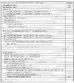
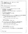
図4及び図5は、量子化残差情報QD(図4ではresidual_coding()と表記)に含まれる各シンタックスが示されている。(Configuration of quantization residual information QD)
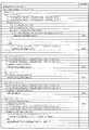
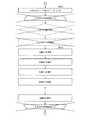
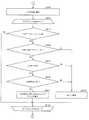
4 and 5 show syntaxes included in the quantization residual information QD (indicated as residual_coding () in FIG. 4).
図4は、量子化残差情報QDに含まれるシンタックスを示すシンタックステーブルの前半部分を示す図である。図5は、量子化残差情報QDに含まれるシンタックスを示すシンタックステーブルの後半部分を示す図である。 FIG. 4 is a diagram illustrating a first half portion of a syntax table indicating syntax included in the quantized residual information QD. FIG. 5 is a diagram illustrating the second half of the syntax table indicating the syntax included in the quantized residual information QD.
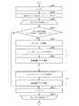
図4及び図5に示すように、量子化残差情報QDは、シンタックスlast_significant_coeff_x、last_significant_coeff_y、significant_coeff_group_flag、significant_coeff_flag、coeff_abs_level_greater1_flag、coeff_abs_level_greater2_flag、coeff_sign_flag、coeff_abs_level_remainingを含んでいる。 4 and 5, the quantization residual information QD includes syntax last_significant_coeff_x, last_significant_coeff_y, significant_coeff_group_flag, significant_coeff_flag, coeff_abs_level_greater1_flag, coeff_abs_level_greater2_flag, coeffresigning_flag_coeffresigning
量子化残差情報QDに含まれる各シンタックスは、コンテキスト適応型2値算術符号化(CABAC)によって符号化されている。 Each syntax included in the quantized residual information QD is encoded by context adaptive binary arithmetic coding (CABAC).
変換係数は、低周波数側から高周波数側に向かって順次スキャンが行われる。このスキャン順を、順スキャンと呼ぶこともある。一方で、順スキャンとは逆に高周波数側から低周波数側のスキャンも用いられる。このスキャン順を、逆スキャンと呼ぶこともある。 The conversion coefficient is sequentially scanned from the low frequency side to the high frequency side. This scan order may be referred to as a forward scan. On the other hand, a scan from the high frequency side to the low frequency side is also used, contrary to the forward scan. This scan order is sometimes called reverse scan.
シンタックスlast_significant_coeff_x及びlast_significant_coeff_yは、順スキャン方向に沿って最後の非0変換係数の位置を示すシンタックスである。 The syntaxes last_significant_coeff_x and last_significant_coeff_y are syntaxes indicating the position of the last non-zero transform coefficient along the forward scan direction.
シンタックスsignificant_coeff_flagは、非0変換係数を起点として逆スキャン方向に沿った各周波数成分について、非0変換係数の有無を示すシンタックスである。シンタックスsignificant_coeff_flagは、各xC、yCについて、変換係数が0であれば0、変換係数が0でなければ1をとるフラグである。なお、シンタックスsignificant_coeff_flagを変換係数有無フラグとも呼称する。なお、significant_coeff_flagを独立のシンタックスとして扱わず、変換係数の絶対値を表すシンタックスcoeff_abs_levelに含まれるとしても良い。この場合、シンタックスcoeff_abs_levelの1ビット目がsignificant_coeff_flagに相当し、以下のsignificant_coeff_flagのコンテキストインテックスを導出する処理は、シンタックスcoeff_abs_levelの1ビット目のコンテキストインデックスを導出する処理に相当する。 The syntax significant_coeff_flag is a syntax indicating whether or not there is a non-zero transform coefficient for each frequency component along the reverse scan direction starting from the non-zero transform coefficient. The syntax significant_coeff_flag is a flag that takes 0 for each xC, yC if the conversion coefficient is 0, and 1 if the conversion coefficient is not 0. The syntax significant_coeff_flag is also referred to as a conversion coefficient presence / absence flag. Note that significant_coeff_flag may not be treated as an independent syntax but may be included in the syntax coeff_abs_level representing the absolute value of the transform coefficient. In this case, the first bit of the syntax coeff_abs_level corresponds to significant_coeff_flag, and the process of deriving the context index of the following significant_coeff_flag corresponds to the process of deriving the context index of the first bit of the syntax coeff_abs_level.
動画像復号装置1の備える可変長符号復号部11は、変換ブロックを複数のサブブロックに分割し、サブブロックを処理単位として、significant_coeff_flagの復号を行う。量子化残差情報QDには、サブブロック単位で、サブブロック内に少なくとも1つの非0変換係数が存在するか否かを示すフラグ(サブブロック係数有無フラグsignificant_coeff_group_flag)が含まれる。 The variable length
以下では、復号処理について、図6〜図8を参照して説明する。 Hereinafter, the decoding process will be described with reference to FIGS.
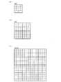
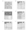
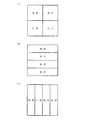
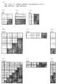
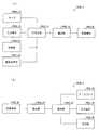
図6は、ブロックとサブブロックの関係を示す図である。図6(a)は、4×4TUが4×4成分からなる1個のサブブロックから構成される例を示す。図6(b)は、8×8TUが4×4成分からなる4個のサブブロックから構成される例を示す。図6(c)は、16×16TUが4×4成分からなる16個のサブブロックから構成される例を示す。なお、TUサイズとサブブロックサイズの関係および分割方法はこの例に限らない。 FIG. 6 is a diagram illustrating the relationship between blocks and sub-blocks. FIG. 6A shows an example in which 4 × 4 TU is composed of one sub-block composed of 4 × 4 components. FIG. 6B shows an example in which 8 × 8 TU is composed of four sub-blocks composed of 4 × 4 components. FIG. 6C shows an example in which 16 × 16 TU is composed of 16 sub-blocks composed of 4 × 4 components. Note that the relationship between the TU size and the sub-block size and the division method are not limited to this example.
図7(a)は、ブロックを分割して得られる複数の(図7(a)では4×4=16個の)サブブロックに対するスキャン順を示す図である。以下では、サブブロックを単位とするスキャンをサブブロックスキャンとも呼ぶ。サブブロックに対して図7(a)のようにスキャンが行われる場合、サブブロック内の各周波数領域に対して図7(b)に示すスキャン順でスキャンが行われる。図7(a)及び図7(b)に示すスキャン順を「順スキャン」とも呼ぶ。 FIG. 7A is a diagram showing a scan order for a plurality of (4 × 4 = 16 in FIG. 7A) sub-blocks obtained by dividing a block. Hereinafter, scanning in units of sub-blocks is also referred to as sub-block scanning. When scanning is performed on the sub-block as shown in FIG. 7A, scanning is performed on each frequency region in the sub-block in the scanning order shown in FIG. 7B. The scan order shown in FIGS. 7A and 7B is also referred to as “forward scan”.
図7(c)は、ブロックを分割して得られる複数の(図7(b)では4×4=16個の)サブブロックに対するスキャン順を示す図である。サブブロックに対して図7(c)のようにスキャンが行われる場合、サブブロック内の各周波数領域に対して図7(d)に示すスキャン順でスキャンが行われる。図7(c)及び図7(d)に示すスキャン順を「逆スキャン」とも呼ぶ。 FIG. 7C is a diagram showing the scan order for a plurality of (4 × 4 = 16 in FIG. 7B) sub-blocks obtained by dividing the block. When the sub block is scanned as shown in FIG. 7C, the scan is performed in the scan order shown in FIG. 7D for each frequency region in the sub block. The scan order shown in FIGS. 7C and 7D is also referred to as “reverse scan”.
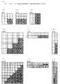
図8(a)〜(f)の横軸は、水平方向周波数xC(0≦xC≦7)を表しており、縦軸は、垂直方向周波数yC(0≦yC≦7)を表している。以下の説明では、周波数領域に含まれる各部分領域のうち、水平方向周波数xC、および、垂直方向周波数yCによって指定される部分領域を、周波数成分(xC、yC)とも呼称する。また、周波数成分(xC、yC)についての変換係数をCoeff(xC、yC)とも表記する。変換係数Coeff(0、0)は、DC成分を示しており、それ以外の変換係数は、DC成分以外の成分を表している。本明細書において、(xC、yC)を(u、v)と表記することもある。 8A to 8F, the horizontal axis represents the horizontal frequency xC (0 ≦ xC ≦ 7), and the vertical axis represents the vertical frequency yC (0 ≦ yC ≦ 7). In the following description, among the partial areas included in the frequency domain, the partial areas specified by the horizontal frequency xC and the vertical frequency yC are also referred to as frequency components (xC, yC). Further, the conversion coefficient for the frequency component (xC, yC) is also expressed as Coeff (xC, yC). The conversion coefficient Coeff (0, 0) indicates a DC component, and the other conversion coefficients indicate components other than the DC component. In this specification, (xC, yC) may be expressed as (u, v).
図8(a)は、TUサイズが8×8であるブロックが4×4のサイズのサブブロックに分割された場合に、順スキャンにて各周波数成分がスキャンされる場合のスキャン順を示す図である。 FIG. 8A is a diagram illustrating a scan order when each frequency component is scanned in a forward scan when a block having a TU size of 8 × 8 is divided into sub-blocks of 4 × 4 size. It is.
図8(b)は、8×8の周波数成分からなる周波数領域における0でない変換係数(非0変換係数)を例示する図である。図8(b)に示す例の場合、last_significant_coeff_x=6、last_significant_coeff_y=0である。 FIG. 8B is a diagram illustrating non-zero transform coefficients (non-zero transform coefficients) in the frequency domain composed of 8 × 8 frequency components. In the example shown in FIG. 8B, last_significant_coeff_x = 6 and last_significant_coeff_y = 0.
図8(c)は、復号対象の変換係数が、図8(b)に示すものである場合の各サブブロックについて復号されたサブブロック係数有無フラグsignificant_coeff_group_flagの各値を示す図である。少なくとも1つの非0変換係数を含むサブブロックに関するsignificant_coeff_group_flagは、値として1をとり、非0変換係数を1つも含まないサブブロックに関するsignificant_coeff_group_flagは、値として0をとる。 FIG. 8C is a diagram illustrating each value of the subblock coefficient presence / absence flag significant_coeff_group_flag decoded for each subblock when the transform coefficient to be decoded is the one shown in FIG. 8B. Significant_coeff_group_flag related to a sub-block including at least one non-zero transform coefficient takes 1 as a value, and significant_coeff_group_flag related to a sub-block including no non-zero transform coefficient takes 0 as a value.
図8(d)は、復号対象の変換係数が、図8(b)に示すものである場合の非0変換係数の有無を示すシンタックスsignificant_coeff_flagの各値を示す図である。significant_coeff_group_flag=1であるサブブロックに対しては、significant_coeff_flagは逆スキャン順に復号され、significant_coeff_group_flag=0であるサブブロックに対しては、当該サブブロックに対するsignificant_coeff_flagの復号処理を行うことなく、当該サブブロックに含まれる全ての周波数成分に対するsignificant_coeff_flagが0に設定される(図8(d)の左下のサブブロック)。 FIG. 8D is a diagram illustrating each value of the syntax significant_coeff_flag indicating the presence or absence of a non-zero transform coefficient when the transform coefficient to be decoded is the one illustrated in FIG. 8B. For a subblock with significant_coeff_group_flag = 1, significant_coeff_flag is decoded in reverse scan order, and for a subblock with significant_coeff_group_flag = 0, it is included in the subblock without performing decoding processing of significant_coeff_flag for the subblock Significant_coeff_flag for all frequency components to be transmitted is set to 0 (lower left subblock in FIG. 8D).
図8(e)は、復号対象の変換係数が、図8(b)に示すものである場合のシンタックスcoeff_abs_level_greater1_flag、coeff_abs_level_greater2_flag、及びcoeff_abs_level_remainingを復号することによって得られた各変換係数の絶対値を示している。 FIG. 8E shows the absolute value of each transform coefficient obtained by decoding the syntax coeff_abs_level_greater1_flag, coeff_abs_level_greater2_flag, and coeff_abs_level_remaining when the transform coefficients to be decoded are those shown in FIG. 8B. ing.
図8(f)は、復号対象の変換係数が、図8(b)に示すものである場合のシンタックスcoeff_sign_flagを示す図である。 FIG. 8F is a diagram illustrating the syntax coeff_sign_flag when the transform coefficients to be decoded are those illustrated in FIG. 8B.
各変換係数の値を示すシンタックスcoeff_abs_level_greater1_flag、coeff_abs_level_greater2_flag、及びcoeff_abs_level_remainingの復号は、モード(ハイスループットモード)により変化する。サブブロックの開始時には、ハイスループットモードがオフであり、サブブロック内の非0係数の数が所定の定数以上となった時点で、ハイスループットモードがオンとなる。ハイスループットモードでは、一部のシンタックスの復号をスキップする。 The decoding of the syntaxes coeff_abs_level_greater1_flag, coeff_abs_level_greater2_flag, and coeff_abs_level_remaining indicating the value of each transform coefficient varies depending on the mode (high throughput mode). At the start of the sub-block, the high-throughput mode is turned off, and the high-throughput mode is turned on when the number of non-zero coefficients in the sub-block becomes equal to or greater than a predetermined constant. In the high throughput mode, decoding of a part of syntax is skipped.
シンタックスcoeff_abs_level_greater1_flagは、変換係数の絶対値が1を越えるものであるのか否かを示すフラグであり、シンタックスsignificant_coeff_flagの値が1である周波数成分について符号化される。変換係数の絶対値が1を越えるものであるとき、coeff_abs_level_greater1_flagの値は1であり、そうでないときにcoeff_abs_level_greater1_flagの値は0である。なお、coeff_abs_level_greater1_flagの復号は、ハイスループットモードの場合にはスキップされる。 The syntax coeff_abs_level_greater1_flag is a flag indicating whether or not the absolute value of the transform coefficient exceeds 1, and is encoded for a frequency component having a syntax significant_coeff_flag value of 1. When the absolute value of the transform coefficient exceeds 1, the value of coeff_abs_level_greater1_flag is 1, otherwise, the value of coeff_abs_level_greater1_flag is 0. Note that the decoding of coeff_abs_level_greater1_flag is skipped in the high throughput mode.
シンタックスcoeff_abs_level_greater2_flagは、変換係数の絶対値が2を越えるものであるのか否かを示すフラグであり、coeff_abs_level_greater1_flagの値が1であるときに符号化される。変換係数の絶対値が2を越えるものであるとき、coeff_abs_level_greater2_flagの値は1であり、そうでないときにcoeff_abs_level_greater2_flagの値は0である。なお、coeff_abs_level_greater2_flagの復号は、各サブブロックで1回目以降、及びハイスループットモードの場合にはスキップされる。 The syntax coeff_abs_level_greater2_flag is a flag indicating whether or not the absolute value of the transform coefficient exceeds 2, and is encoded when the value of coeff_abs_level_greater1_flag is 1. When the absolute value of the transform coefficient exceeds 2, the value of coeff_abs_level_greater2_flag is 1, otherwise, the value of coeff_abs_level_greater2_flag is 0. Note that the decoding of coeff_abs_level_greater2_flag is skipped for the first and subsequent times in each sub-block, and in the high-throughput mode.
シンタックスcoeff_abs_level_remainingは、変換係数の絶対値が所定のベースレベルbaseLevelである場合に、当該変換係数の絶対値を指定するためのシンタックスであり、coeff_abs_level_greater1_flagの復号がスキップされる場合、coeff_abs_level_greater2_flagがスキップされcoeff_abs_level_greater1_flagが1の場合、coeff_abs_level_greater2_flagの値が1であるときに符号化される。シンタックスcoeff_abs_remainingの値は、変換係数の絶対値からbaseLevelを引いたものである。例えば、coeff_abs_level_remaining=1は、変換係数の絶対値がbaseLevel+1であることを示している。なお、baseLevelは以下のように定まる。 The syntax coeff_abs_level_remaining is a syntax for specifying the absolute value of the transform coefficient when the absolute value of the transform coefficient is a predetermined base level baseLevel. When decoding of coeff_abs_level_greater1_flag is skipped, coeff_abs_level_greater2_flag is skipped. When coeff_abs_level_greater1_flag is 1, it is encoded when the value of coeff_abs_level_greater2_flag is 1. The value of the syntax coeff_abs_remaining is obtained by subtracting baseLevel from the absolute value of the transform coefficient. For example, coeff_abs_level_remaining = 1 indicates that the absolute value of the transform coefficient is
baseLevel = 1 (coeff_abs_level_greater1_flagの復号がスキップされた場合)
baseLevel = 2 (上記以外でcoeff_abs_level_greater2_flagの復号がスキップされた場合)
baseLevel = 3 (上記以外でcoeff_abs_level_greater2_flagが1の場合)
シンタックスcoeff_sign_flagは、変換係数の符号(正であるのか負であるのか)を示すフラグであり、サインハイディングが行われる場合を除き、シンタックスsignificant_coeff_flagの値が1である周波数成分について符号化される。シンタックスcoeff_sign_flagは、変換係数が正である場合に1をとり、変換係数が負である場合に0をとる。baseLevel = 1 (when decoding of coeff_abs_level_greater1_flag is skipped)
baseLevel = 2 (when decoding of coeff_abs_level_greater2_flag is skipped except above)
baseLevel = 3 (other than above, when coeff_abs_level_greater2_flag is 1)
The syntax coeff_sign_flag is a flag indicating the sign of the transform coefficient (whether positive or negative), and is encoded for frequency components whose syntax significant_coeff_flag value is 1, except when sign hiding is performed. The The syntax coeff_sign_flag takes 1 when the transform coefficient is positive, and takes 0 when the transform coefficient is negative.
なお、サインハイディングとは、変換係数の符号を明示的に符号化せず、計算により算出する方法を言う。 Note that sign hiding refers to a method of calculating by calculation without explicitly encoding the sign of the transform coefficient.
動画像復号装置1の備える可変長符号復号部11は、シンタックスlast_significant_coeff_x、last_significant_coeff_y、significant_coeff_flag、coeff_abs_level_greater1_flag、coeff_abs_level_greater2_flag、coeff_sign_flag、coeff_abs_level_remainingを復号することにより、各周波数成分についての変換係数Coeff(xC、yC)を生成することができる。 The variable-length
なお、特定の領域(例えばTU)内の非0変換係数の集合をsignificance mapと呼ぶこともある。 A set of non-zero transform coefficients in a specific area (for example, TU) may be referred to as a significance map.
各種シンタックスの復号処理の詳細については、後述することとし、続いて動画像復号装置1の構成について説明を行う。 Details of the decoding processing of various syntaxes will be described later, and the configuration of the moving
(動画像復号装置1)
以下では、本実施形態に係る動画像復号装置1について図1、図9〜図26を参照して説明する。動画像復号装置1は、H.264/MPEG−4 AVC規格の後継コーデックであるHEVC(High-Efficiency Video Coding)にて提案されている技術を実装している復号装置である。(Moving picture decoding apparatus 1)
Below, the moving
図9は、動画像復号装置1の構成を示すブロック図である。図9に示すように、動画像復号装置1は、可変長符号復号部11、予測画像生成部12、逆量子化・逆変換部13、加算器14、フレームメモリ15、および、ループフィルタ16を備えている。また、図9に示すように、予測画像生成部12は、動きベクトル復元部12a、インター予測画像生成部12b、イントラ予測画像生成部12c、および、予測方式決定部12dを備えている。動画像復号装置1は、符号化データ#1を復号することによって動画像#2を生成するための装置である。 FIG. 9 is a block diagram showing a configuration of the moving
(可変長符号復号部11)
図10は、可変長符号復号部11の要部構成を示すブロック図である。図10に示すように、可変長符号復号部11は、量子化残差情報復号部111、予測パラメータ復号部112、予測タイプ情報復号部113、および、フィルタパラメータ復号部114を備えている。(Variable-length code decoding unit 11)
FIG. 10 is a block diagram illustrating a main configuration of the variable-length
可変長符号復号部11は、予測パラメータ復号部112にて、各パーティションに関する予測パラメータPPを、符号化データ#1から復号し、予測画像生成部12に供給する。具体的には、予測パラメータ復号部112は、インター予測パーティションに関しては、参照画像インデックス、推定動きベクトルインデックス、及び、動きベクトル残差を含むインター予測パラメータPP_Interを符号化データ#1から復号し、これらを動きベクトル復元部12aに供給する。一方、イントラ予測パーティションに関しては、推定予測モードフラグ、推定予測モードインデックス、および、残余予測モードインデックスを含むイントラ予測パラメータPP_Intraを符号化データ#1から復号し、これらをイントラ予測画像生成部12cに供給する。 In the variable length
また、可変長符号復号部11は、予測タイプ情報復号部113にて、各パーティションについての予測タイプ情報Pred_typeを符号化データ#1から復号し、これを予測方式決定部12dに供給する。更に、可変長符号復号部11は、量子化残差情報復号部111にて、ブロックに関する量子化残差情報QD、及び、そのブロックを含むTUに関する量子化パラメータ差分Δqpを符号化データ#1から復号し、これらを逆量子化・逆変換部13に供給する。また、可変長符号復号部11は、フィルタパラメータ復号部114にて、符号化データ#1からフィルタパラメータFPを復号し、これをループフィルタ16に供給する。なお、量子化残差情報復号部111の具体的な構成については後述するためここでは説明を省略する。 Further, the variable length
(予測画像生成部12)
予測画像生成部12は、各パーティションについての予測タイプ情報Pred_typeに基づいて、各パーティションがインター予測を行うべきインター予測パーティションであるのか、イントラ予測を行うべきイントラ予測パーティションであるのかを識別する。そして、前者の場合には、インター予測画像Pred_Interを生成すると共に、生成したインター予測画像Pred_Interを予測画像Predとして加算器14に供給し、後者の場合には、イントラ予測画像Pred_Intraを生成すると共に、生成したイントラ予測画像Pred_Intraを加算器14に供給する。なお、予測画像生成部12は、処理対象PUに対してスキップモードが適用されている場合には、当該PUに属する他のパラメータの復号を省略する。(Predicted image generation unit 12)
The predicted
(動きベクトル復元部12a)
動きベクトル復元部12aは、各インター予測パーティションに関する動きベクトルmvを、そのパーティションに関する動きベクトル残差と、他のパーティションに関する復元済みの動きベクトルmv’とから復元する。具体的には、(1)推定動きベクトルインデックスにより指定される推定方法に従って、復元済みの動きベクトルmv’から推定動きベクトルを導出し、(2)導出した推定動きベクトルと動きベクトル残差とを加算することによって動きベクトルmvを得る。なお、他のパーティションに関する復元済みの動きベクトルmv’は、フレームメモリ15から読み出すことができる。動きベクトル復元部12aは、復元した動きベクトルmvを、対応する参照画像インデックスRIと共に、インター予測画像生成部12bに供給する。(Motion
The motion
(インター予測画像生成部12b)
インター予測画像生成部12bは、画面間予測によって、各インター予測パーティションに関する動き補償画像mcを生成する。具体的には、動きベクトル復元部12aから供給された動きベクトルmvを用いて、同じく動きベクトル復元部12aから供給された参照画像インデックスRIによって指定される適応フィルタ済復号画像P_ALF’から動き補償画像mcを生成する。ここで、適応フィルタ済復号画像P_ALF’は、既にフレーム全体の復号が完了した復号済みの復号画像に対して、ループフィルタ16によるフィルタ処理を施すことによって得られる画像であり、インター予測画像生成部12bは、適応フィルタ済復号画像P_ALF’を構成する各画素の画素値をフレームメモリ15から読み出すことができる。インター予測画像生成部12bによって生成された動き補償画像mcは、インター予測画像Pred_Interとして予測方式決定部12dに供給される。(Inter prediction
The inter prediction
(イントラ予測画像生成部12c)
イントラ予測画像生成部12cは、各イントラ予測パーティションに関する予測画像Pred_Intraを生成する。具体的には、まず、可変長符号復号部11から供給されたイントラ予測パラメータPP_Intraに基づいて予測モードを特定し、特定された予測モードを対象パーティションに対して、例えば、ラスタスキャン順に割り付ける。(Intra predicted
The intra predicted
ここで、イントラ予測パラメータPP_Intraに基づく予測モードの特定は、以下のように行うことができる。(1)推定予測モードフラグを復号し、当該推定予測モードフラグが、処理対象である対象パーティションについての予測モードと、当該対象パーティションの周辺のパーティションに割り付けられた予測モードとが同一であることを示している場合には、対象パーティションに対して、当該対象パーティションの周辺のパーティションに割り付けられた予測モードを割り付ける。(2)一方で、推定予測モードフラグが、処理対象である対象パーティションについての予測モードと、当該対象パーティションの周辺のパーティションに割り付けられた予測モードとが同一でないことを示している場合には、残余予測モードインデックスを復号し、当該残余予測モードインデックスの示す予測モードを対象パーティションに対して割り付ける。 Here, the prediction mode based on the intra prediction parameter PP_Intra can be specified as follows. (1) The estimated prediction mode flag is decoded, and the estimated prediction mode flag indicates that the prediction mode for the target partition to be processed is the same as the prediction mode assigned to the peripheral partition of the target partition. If the target partition is indicated, the prediction mode assigned to the partition around the target partition is assigned to the target partition. (2) On the other hand, when the estimated prediction mode flag indicates that the prediction mode for the target partition to be processed is not the same as the prediction mode assigned to the partitions around the target partition, The residual prediction mode index is decoded, and the prediction mode indicated by the residual prediction mode index is assigned to the target partition.
イントラ予測画像生成部12cは、対象パーティションに割り付けられた予測モードの示す予測方法に従って、画面内予測によって、(局所)復号画像Pから予測画像Pred_Intraを生成する。イントラ予測画像生成部12cによって生成されたイントラ予測画像Pred_Intraは、予測方式決定部12dに供給される。なお、イントラ予測画像生成部12cは、画面内予測によって、適応フィルタ済復号画像P_ALFから予測画像Pred_Intraを生成する構成とすることも可能である。 The intra predicted
図11を用いて、予測モードの定義について説明する。図11は、予測モードの定義を示している。同図に示すように、36種類の予測モードが定義されており、それぞれの予測モードは、「0」〜「35」の番号(イントラ予測モードインデックス)によって特定される。また、図12に示すように、各予測モードには次のような名称が割り当てられている。すなわち、「0」は、“Intra_Planar(プラナー予測モード、平面予測モード)”であり、「1」は、“Intra DC(イントラDC予測モード)”であり、「2」〜「34」は、“Intra Angular(方向予測)”であり、「35」は、“Intra From Luma”である。「35」は、色差予測モード固有のものであり、輝度の予測に基づいて色差の予測を行うモードである。言い換えれば、色差予測モード「35」は、輝度画素値と色差画素値との相関を利用した予測モードである。色差予測モード「35」はLMモードとも称する。予測モード数(intraPredModeNum)は、対象ブロックのサイズによらず「35」である。 The definition of the prediction mode will be described with reference to FIG. FIG. 11 shows the definition of the prediction mode. As shown in the figure, 36 types of prediction modes are defined, and each prediction mode is specified by a number (intra prediction mode index) from “0” to “35”. Further, as shown in FIG. 12, the following names are assigned to the respective prediction modes. That is, “0” is “Intra_Planar (planar prediction mode, plane prediction mode)”, “1” is “Intra DC (intra DC prediction mode)”, and “2” to “34” are “ "Intra Angular (direction prediction)" and "35" is "Intra From Luma". “35” is unique to the color difference prediction mode, and is a mode for performing color difference prediction based on luminance prediction. In other words, the color difference prediction mode “35” is a prediction mode using the correlation between the luminance pixel value and the color difference pixel value. The color difference prediction mode “35” is also referred to as an LM mode. The number of prediction modes (intraPredModeNum) is “35” regardless of the size of the target block.
(予測方式決定部12d)
予測方式決定部12dは、各パーティションが属するPUについての予測タイプ情報Pred_typeに基づいて、各パーティションがインター予測を行うべきインター予測パーティションであるのか、イントラ予測を行うべきイントラ予測パーティションであるのかを決定する。そして、前者の場合には、インター予測画像生成部12bにて生成されたインター予測画像Pred_Interを予測画像Predとして加算器14に供給し、後者の場合には、イントラ予測画像生成部12cにて生成されたイントラ予測画像Pred_Intraを予測画像Predとして加算器14に供給する。(Prediction
The prediction
(逆量子化・逆変換部13)
逆量子化・逆変換部13は、(1)符号化データ#1の量子化残差情報QDから復号された変換係数Coeffを逆量子化し、(2)逆量子化によって得られた変換係数Coeff_IQに対して逆DCT(Discrete Cosine Transform)変換等の逆周波数変換を施し、(3)逆周波数変換によって得られた予測残差Dを加算器14に供給する。なお、量子化残差情報QDから復号された変換係数Coeffを逆量子化する際に、逆量子化・逆変換部13は、可変長符号復号部11から供給された量子化パラメータ差分Δqpから量子化ステップQPを導出する。量子化パラメータqpは、直前に逆量子化及び逆周波数変換したTUに関する量子化パラメータqp’に量子化パラメータ差分Δqpを加算することによって導出でき、量子化ステップQPは、量子化パラメータqpから例えばQP=2pq/6によって導出できる。また、逆量子化・逆変換部13による予測残差Dの生成は、TUあるいはTUを分割したブロックを単位として行われる。(Inverse quantization / inverse transform unit 13)
The inverse quantization / inverse transform unit 13 (1) inversely quantizes the transform coefficient Coeff decoded from the quantized residual information QD of the encoded
なお、逆量子化・逆変換部13によって行われる逆DCT変換は、例えば、対象ブロックのサイズが8×8画素である場合、当該対象ブロックにおける画素の位置を(i、j)(0≦i≦7、0≦j≦7)とし、位置(i、j)における予測残差Dの値をD(i、j)と表すことにし、周波数成分(u、v)(0≦u≦7、0≦v≦7)における逆量子化された変換係数をCoeff_IQ(u、v)と表すことにすると、例えば、以下の数式(1)によって与えられる。 For example, when the size of the target block is 8 × 8 pixels, the inverse DCT transform performed by the inverse quantization /

・C(u)=1/√2 (u=0)
・C(u)=1 (u≠0)
・C(v)=1/√2 (v=0)
・C(v)=1 (v≠0)
(加算器14)
加算器14は、予測画像生成部12から供給された予測画像Predと、逆量子化・逆変換部13から供給された予測残差Dとを加算することによって復号画像Pを生成する。生成された復号画像Pは、フレームメモリ15に格納される。・ C (u) = 1 / √2 (u = 0)
・ C (u) = 1 (u ≠ 0)
・ C (v) = 1 / √2 (v = 0)
・ C (v) = 1 (v ≠ 0)
(Adder 14)
The
(ループフィルタ16)
ループフィルタ16は、(1)復号画像Pにおけるブロック境界、またはパーティション境界の周辺の画像の平滑化(デブロック処理)を行うデブロッキングフィルタ(DF:Deblocking Filter)としての機能と、(2)デブロッキングフィルタが作用した画像に対して、フィルタパラメータFPを用いて適応フィルタ処理を行う適応フィルタ(ALF:Adaptive Loop Filter)としての機能とを有している。(Loop filter 16)
The
(量子化残差情報復号部111)
量子化残差情報復号部111は、符号化データ#1に含まれる量子化残差情報QDから、各周波数成分(xC、yC)についての量子化された変換係数Coeff(xC、yC)を復号するための構成である。ここで、xCおよびyCは、周波数領域における各周波数成分の位置を表すインデックスであり、それぞれ、上述した水平方向周波数uおよび垂直方向周波数vに対応するインデックスである。以下では、量子化された変換係数Coeffを、単に、変換係数Coeffと呼ぶこともある。(Quantization residual information decoding unit 111)
The quantization residual
図1は、量子化残差情報復号部111の構成を示すブロック図である。図1に示すように、量子化残差情報復号部111は、変換係数復号部120及び算術符号復号部130を備えている。 FIG. 1 is a block diagram showing a configuration of the quantized residual
(算術符号復号部130)
算術符号復号部130は、量子化残差情報QDに含まれる各ビットをコンテキストを参照して復号するための構成であり、図1に示すように、コンテキスト記録更新部131及びビット復号部132を備えている。(Arithmetic Code Decoding Unit 130)
The arithmetic
(コンテキスト記録更新部131)
コンテキスト記録更新部131は、各コンテキストインデックスctxIdxによって管理されるコンテキスト変数CVを記録及び更新するための構成である。ここで、コンテキスト変数CVには、(1)発生確率が高い優勢シンボルMPS(most probable symbol)と、(2)その優勢シンボルMPSの発生確率を指定する確率状態インデックスpStateIdxとが含まれている。(Context record update unit 131)
The context recording / updating
コンテキスト記録更新部131は、変換係数復号部120の備える各部から供給されるコンテキストインデックスctxIdx及びビット復号部132によって復号されたBinの値を参照することによってコンテキスト変数CVを更新すると共に、更新されたコンテキスト変数CVを次回更新されるまで記録する。なお、優勢シンボルMPSは0か1である。また、優勢シンボルMPSと確率状態インデックスpStateIdxは、ビット復号部132がBinを1つ復号する毎に更新される。 The context
また、コンテキストインデックスctxIdxは、各周波数成分についてのコンテキストを直接指定するものであってもよいし、処理対象のTU毎に設定されるコンテキストインデックスのオフセットからの増分値であってもよい(以下同様)。 The context index ctxIdx may directly specify the context for each frequency component, or may be an increment value from the context index offset set for each TU to be processed (the same applies hereinafter). ).
(ビット復号部132)
ビット復号部132は、コンテキスト記録更新部131に記録されているコンテキスト変数CVを参照し、量子化残差情報QDに含まれる各ビット(Binとも呼ぶ)を復号する。また、復号して得られたBinの値を変換係数復号部120の備える各部に供給する。また、復号して得られたBinの値は、コンテキスト記録更新部131にも供給され、コンテキスト変数CVを更新するために参照される。(Bit decoding unit 132)
The
(変換係数復号部120)
図1に示すように、変換係数復号部120は、ラスト係数位置復号部121、スキャン順テーブル格納部122、係数復号制御部123、係数有無フラグ復号部、係数値復号部125、復号係数記憶部126、及び、サブブロック係数有無フラグ復号部127を備えている。(Transform coefficient decoding unit 120)
As shown in FIG. 1, the transform
(ラスト係数位置復号部121)
ラスト係数位置復号部121は、ビット復号部132より供給される復号ビット(Bin)を解釈し、シンタックスlast_significant_coeff_x及びlast_significant_coeff_yを復号する。復号したシンタックスlast_significant_coeff_x及びlast_significant_coeff_yは、係数復号制御部123に供給される。また、ラスト係数位置復号部121は、算術符号復号部130にてシンタックスlast_significant_coeff_x及びlast_significant_coeff_yのBinを復号するために用いられるコンテキストを決定するためのコンテキストインデックスctxIdxを算出する。算出されたコンテキストインデックスctxIdxは、コンテキスト記録更新部131に供給される。ラスト係数位置復号部121の具体的な構成例については後述する。(Last coefficient position decoding unit 121)
The last coefficient
(スキャン順テーブル格納部122)
スキャン順テーブル格納部122には、処理対象のTU(ブロック)のサイズ、スキャン方向の種別を表すスキャンインデックス、及びスキャン順に沿って付与された周波数成分識別インデックスを引数として、処理対象の周波数成分の周波数領域における位置を与えるテーブルが格納されている。(Scan order table storage unit 122)
The scan order
このようなスキャン順テーブルの一例としては、図4及び図5に示したScanOrderが挙げられる。図4及び図5に示したScanOrderにおいて、log2TrafoWidthは、処理対象のTUの横幅のサイズを表わし、log2TrafoHeightは、処理対象のTUの縦幅のサイズを表わしており、scanIdxはスキャンインデックスを表しており、nは、スキャン順に沿って付与された周波数成分識別インデックスを表している。また、図4及び図5において、xC及びyCは、処理対象の周波数成分の周波数領域における位置を表している。 An example of such a scan order table is ScanOrder shown in FIGS. 4 and 5. In ScanOrder shown in FIGS. 4 and 5, log2TrafoWidth represents the horizontal size of the TU to be processed, log2TrafoHeight represents the vertical size of the TU to be processed, and scanIdx represents the scan index. , N represent frequency component identification indexes given along the scan order. 4 and 5, xC and yC represent the positions of the frequency components to be processed in the frequency domain.
また、スキャン順テーブル格納部122に格納されたテーブルは、処理対象のTU(ブロック)のサイズとイントラ予測モードの予測モードインデックスとに関連付けられたスキャンインデックスscanIdxによって指定される。処理対象のTUに用いられた予測方法がイントラ予測である場合には、係数復号制御部123は、当該TUのサイズと当該TUの予測モードとに関連付けられたスキャンインデックスscanIdxによって指定されるテーブルを参照して周波数成分のスキャン順を決定する。 The table stored in the scan order
図13は、イントラ予測モードインデックスIntraPredModeと、TUサイズを指定する値log2TrafoSizeとによって指定されるスキャンインデックスscanIdxの例を示している。図13において、log2TrafoSize-2=0は、TUサイズが4×4(4×4画素に対応)であることを示しており、log2TrafoSize-2=1は、TUサイズが8×8(8×8画素に対応)であることを示している。図13に示すように、例えば、TUサイズが4×4であり、イントラ予測モードインデックスが1であるとき、スキャンインデックス=0が用いられ、TUサイズが4×4であり、イントラ予測モードインデックスが6であるとき、スキャンインデックス=2が用いられる。 FIG. 13 illustrates an example of the scan index scanIdx specified by the intra prediction mode index IntraPredMode and the value log2TrafoSize specifying the TU size. In FIG. 13, log2TrafoSize-2 = 0 indicates that the TU size is 4 × 4 (corresponding to 4 × 4 pixels), and log2TrafoSize-2 = 1 indicates that the TU size is 8 × 8 (8 × 8 Corresponding to a pixel). As shown in FIG. 13, for example, when the TU size is 4 × 4 and the intra prediction mode index is 1, scan index = 0 is used, the TU size is 4 × 4, and the intra prediction mode index is When 6, scan index = 2 is used.
図14(a)は、スキャンインデックスscanIdxの各値によって指定されるスキャンタイプScanTypeを示している。図14(a)に示すように、スキャンインデックスが0であるとき、斜め方向スキャン(Up-right diagonal scan)が指定され、スキャンインデックスが1であるとき、水平方向優先スキャン(horizontal fast scan)が指定され、スキャンインデックスが2であるとき、垂直方向優先スキャン(vertical fact scan)が指定される。 FIG. 14A shows the scan type ScanType specified by each value of the scan index scanIdx. As shown in FIG. 14A, when the scan index is 0, an up-right diagonal scan is designated, and when the scan index is 1, a horizontal fast scan is performed. When specified and the scan index is 2, a vertical fact scan is specified.
また、図14(b)〜(d)は、TUサイズが4×4成分であるときの、水平方向優先スキャン(horizontal fast scan)、垂直方向優先スキャン(vertical fact scan)、及び、斜め方向スキャン(Up-right diagonal scan)の各スキャンのスキャン順を示している。図14(b)〜(d)において各周波数成分に付された番号は、該周波数成分がスキャンされる順番を示している。また、図14(b)〜(d)に示す各例は、順スキャン方向を示している。なお、図14(b)〜(d)のスキャンは4×4TUサイズに限らず、4×4のサブブロックで使用しても良い。また、同様のスキャンを4×4より大きいTUやサブブロックで使用しても良い。なお、水平方向優先スキャンの一つの定義は、変換係数の位置を(xC、yC)で表現する場合において、xC + yC =k(k > TH、THは所定の定数)を満たす変換係数で、x = yの軸に対して互いに対称な(xC0, yC0)、(yC0, xC0)を抜きだした場合に、水平方向位置が小さい方の変換係数(xC0 < yC0の場合には(xC0, yC0))が先にスキャンされることである。垂直方向スキャンは逆の定義となる。また、水平方向優先スキャン、垂直方向優先スキャンは本定義に限らない。 FIGS. 14B to 14D show horizontal fast scan, vertical fact scan, and diagonal scan when the TU size is 4 × 4 components. The scan order of each scan of (Up-right diagonal scan) is shown. The numbers assigned to the frequency components in FIGS. 14B to 14D indicate the order in which the frequency components are scanned. Further, each example illustrated in FIGS. 14B to 14D indicates the forward scan direction. The scans in FIGS. 14B to 14D are not limited to the 4 × 4 TU size, and may be used in 4 × 4 sub-blocks. Similar scanning may be used for TUs and sub-blocks larger than 4 × 4. One definition of horizontal priority scan is a conversion coefficient satisfying xC + yC = k (k> TH, TH is a predetermined constant) when the position of the conversion coefficient is expressed by (xC, yC). When (xC0, yC0) and (yC0, xC0) that are symmetrical with respect to the axis of x = y are extracted, the conversion factor with the smaller horizontal position (if xC0 <yC0, (xC0, yC0 )) Is to be scanned first. Vertical scan is the opposite definition. Further, the horizontal direction priority scan and the vertical direction priority scan are not limited to this definition.
図14(e)、(f)は、水平方向優先スキャンと垂直方向優先スキャンの別の例を示す。本例では8×2と2×8のTUサイズもしくはサブブロックで使用される例を示す。 FIGS. 14E and 14F show another example of the horizontal direction priority scan and the vertical direction priority scan. In this example, 8 × 2 and 2 × 8 TU sizes or sub-blocks are used.
(サブブロックスキャン順テーブル)
また、スキャン順テーブル格納部122には、サブブロックのスキャン順を指定するためのサブブロックスキャン順テーブルが格納されている。サブブロックスキャン順テーブルは、処理対象のTU(ブロック)のサイズとイントラ予測モードの予測モードインデックス(予測方向)とに関連付けられたスキャンインデックスscanIdxによって指定される。処理対象のTUに用いられた予測方法がイントラ予測である場合には、係数復号制御部123は、当該TUのサイズと当該TUの予測モードとに関連付けられたスキャンインデックスscanIdxによって指定されるテーブルを参照してサブブロックのスキャン順を決定する。(Sub-block scan order table)
The scan order
(スキャン順テーブル格納部122の別の構成例1)
図48は、TUサイズからスキャン順を導出する方法を示す図である。図48(a)に示すように、TUサイズの幅と高さが一致する場合には、scanIdx = 0、すなわち、スキャンとしてジグザグスキャンもしくはダイアゴナルスキャンを用いる。TUサイズの幅が高さよりも大きい場合には、scanIdx = 1、すなわち、スキャンとして水平方向優先スキャン(水平優先のスキャン)を用いる。TUサイズの高さが幅よりも大きい場合には、scanIdx = 2、すなわち、スキャンとして垂直方向優先スキャン(垂直優先のスキャン)を用いる。なお、本例では、上記スキャン順は、サブブロック内スキャン順とサブブロックスキャン順の両者を示すこととする。すなわちサブブロック内スキャン順とサブブロックスキャン順の両者とも上記方法で導出するものとするが、サブブロック内スキャン順とサブブロックスキャン順の一方を上記方法で導出しても良い。図48(b)は、図48(a)に示すTUサイズとスキャン順との関係を実現する擬似コードである。(Another configuration example 1 of the scan order table storage unit 122)
FIG. 48 is a diagram illustrating a method of deriving the scan order from the TU size. As shown in FIG. 48A, when the width and height of the TU size match, scanIdx = 0, that is, zigzag scan or diagonal scan is used as the scan. When the width of the TU size is larger than the height, scanIdx = 1, that is, the horizontal direction priority scan (horizontal priority scan) is used as the scan. When the height of the TU size is larger than the width, scanIdx = 2, that is, the vertical direction priority scan (vertical priority scan) is used as the scan. In the present example, the scan order indicates both the intra-sub-block scan order and the sub-block scan order. That is, both the intra-sub-block scan order and the sub-block scan order are derived by the above method, but one of the intra-sub-block scan order and the sub-block scan order may be derived by the above method. FIG. 48B is a pseudo code that realizes the relationship between the TU size and the scan order shown in FIG.
TUサイズが非正方の場合、幅および高さのサイズが小さい軸についてDC成分に近い成分に非0係数が集中する。言い換えると、TUの横>TUの高さであれば垂直軸に対して0に近い方に非0係数が集中し水平方向に広がる。この場合、図48に示すように、非0係数が集中する変換係数を先にスキャンするスキャン順を用いることによって符号化効率向上の効果を奏する。なお、TUサイズによるサブブロック選択は、インター予測の場合に好適に用いられる。 When the TU size is non-square, non-zero coefficients are concentrated on a component close to the DC component for an axis having a small width and height size. In other words, if the width of the TU is higher than the height of the TU, non-zero coefficients are concentrated near the vertical axis and spread in the horizontal direction. In this case, as shown in FIG. 48, there is an effect of improving the coding efficiency by using a scan order in which transform coefficients in which non-zero coefficients are concentrated are scanned first. Note that subblock selection based on the TU size is preferably used in the case of inter prediction.
(スキャン順テーブル格納部122の別の構成例2)
図82は、CU予測方式情報PredMode、TUサイズ及びイントラ予測モードインデックスIntraPredModeにより、スキャン順を導出する方法を示す図である。CU予測方式情報PredModeがイントラ予測の場合には、上記で図13を用いて説明したようにTUサイズ及びイントラ予測モードインデックスIntraPredModeに基づいてスキャン順を導出する。(Another configuration example 2 of the scan order table storage unit 122)
FIG. 82 is a diagram illustrating a method of deriving a scan order based on CU prediction method information PredMode, a TU size, and an intra prediction mode index IntraPredMode. When the CU prediction method information PredMode is intra prediction, the scan order is derived based on the TU size and the intra prediction mode index IntraPredMode as described above with reference to FIG.
CU予測方式情報PredModeがインター予測の場合には、上記で図48を用いて説明したようにTUサイズに基づいてスキャン順を導出する。TUサイズが、TUサイズの幅と高さが一致する場合には水平優先および垂直優先以外のスキャン順を使用する。TUサイズの幅と高さが一致しない場合で、TUサイズの幅が高さよりも大きい場合には、水平優先のスキャン順を使用する。一方、TUサイズの高さが幅よりも大きい場合には、垂直優先のスキャン順を使用する。 When the CU prediction method information PredMode is inter prediction, the scan order is derived based on the TU size as described above with reference to FIG. When the TU size matches the width and height of the TU size, a scan order other than horizontal priority and vertical priority is used. When the width and height of the TU size do not match and the width of the TU size is larger than the height, the horizontal priority scan order is used. On the other hand, when the height of the TU size is larger than the width, the vertical priority scan order is used.
以上の構成により、スキャン順を用いることによって、CUがイントラ予測の場合にもインター予測に場合にも、変換係数の偏りに応じて適切なスキャン順が行われるため符号化効率が向上する。 With the above configuration, by using the scan order, an appropriate scan order is performed according to the bias of the transform coefficient, regardless of whether the CU is intra prediction or inter prediction, thereby improving the coding efficiency.
(係数復号制御部123)
係数復号制御部123は、量子化残差情報復号部111の備える各部における復号処理の順序を制御するための構成である。(Coefficient decoding control unit 123)
The coefficient
係数復号制御部123は、図示しないサブブロック分割部129を備える。サブブロック分割部129は、TUを各サブブロックに分割する。サブブロック分割部129の詳細は後述する。 The coefficient
係数復号制御部123は、ラスト係数位置復号部121から供給されるシンタックスlast_significant_coeff_x及びlast_significant_coeff_yを参照し、順スキャンに沿った最後の非0変換係数の位置を特定すると共に、特定した最後の非0変換係数を含むサブブロックの位置を起点とするスキャン順であって、スキャン順テーブル格納部122に格納されたサブブロックスキャン順テーブルによって与えられるスキャン順の逆スキャン順に、各サブブロックの位置(xCG、yCG)を、サブブロック係数有無フラグ復号部127に供給する。 The coefficient
また、係数復号制御部123は、処理対象となるサブブロックに関して、スキャン順テーブル格納部122に格納されたスキャン順テーブルよって与えられるスキャン順の逆スキャン順に、当該処理対象となるサブブロックに含まれる各周波数成分の位置(xC、yC)を、係数有無フラグ復号部124及び復号係数記憶部126に供給する。ここで、処理対象となるサブブロックに含まれる各周波数成分のスキャン順としては、イントラ予測の場合には、イントラ予測モードインデックスIntraPredModeと、TUサイズを指定する値log2TrafoSizeとによって指定されるスキャンインデックスscanIdxの示すスキャン順(水平方向優先スキャン、垂直方向優先スキャン、斜め方向スキャンのいずれか)を用い、インター予測の場合には、斜め方向スキャン(Up-right diagonal scan)を用いればよい。 Also, the coefficient
このように、係数復号制御部123は、処理対象の単位領域(ブロック、TU)に適用された予測方式がイントラ予測である場合に、該イントラ予測の予測方向に応じて、サブブロックスキャン順を設定する構成である。 As described above, when the prediction scheme applied to the unit region (block, TU) to be processed is intra prediction, the coefficient
一般に、イントラ予測モードと変換係数の偏りとは互いに相関を有しているため、イントラ予測モードに応じてスキャン順を切り替えることにより、サブブロック係数有無フラグ、係数有無フラグの偏りに適したスキャンを行うことができる。これによって、符号化及び復号対象となるサブブロック係数有無フラグおよび係数有無フラグの符号量を削減することができるので、処理量が削減されると共に、符号化効率が向上する。 In general, the intra prediction mode and the bias of the transform coefficient are correlated with each other. Therefore, by switching the scan order according to the intra prediction mode, a scan suitable for the bias of the subblock coefficient presence / absence flag and the coefficient presence / absence flag is performed. It can be carried out. As a result, the coding amount of the subblock coefficient presence / absence flag and coefficient presence / absence flag to be encoded and decoded can be reduced, so that the processing amount is reduced and the coding efficiency is improved.
(サブブロック分割手段129)
サブブロック分割手段129は、サブブロック分割手段129は、スキャン順およびTUサイズに応じてに応じてサブブロックサイズを導出し、導出されたサブブロックサイズでTUを分割することでTUをサブブロックに分割する。以下、サブブロックサイズの導出方法を順に説明する。なお、既に説明したように、スキャン順が、CU予測方式情報PredMode、TUサイズ及びイントラ予測モードインデックスIntraPredModeで定まる場合には、CU予測方式情報PredMode、TUサイズ及びイントラ予測モードインデックスIntraPredModeにより、サブブロックサイズを導出する構成も等価である。(Sub-block dividing means 129)
The sub-block dividing unit 129 derives a sub-block size according to the scan order and the TU size, and divides the TU into the sub-block by dividing the TU by the derived sub-block size. To divide. Hereinafter, the sub block size derivation method will be described in order. As already described, when the scan order is determined by the CU prediction method information PredMode, the TU size, and the intra prediction mode index IntraPredMode, the sub-block is determined by the CU prediction method information PredMode, the TU size, and the intra prediction mode index IntraPredMode. The configuration for deriving the size is also equivalent.
(スキャン順からサブブロックサイズを導出する方法)
図50は、スキャン順からサブブロックサイズを導出する方法を示す図である。図50(a)に示すように、スキャン順がジグザグスキャンもしくはダイアゴナルスキャンの場合には4×4のサブブロックを使用する。スキャン順が水平方向優先スキャンの場合には、8×2のサブブロックを使用する。スキャン順が垂直方向優先スキャンの場合には、2×8のサブブロックを使用する。図50(b)は、図50(a)に示すスキャン順とサブブロックサイズとの関係を実現する擬似コードである。(Method of deriving sub-block size from scan order)
FIG. 50 is a diagram illustrating a method for deriving the sub-block size from the scan order. As shown in FIG. 50A, when the scan order is zigzag scan or diagonal scan, 4 × 4 sub-blocks are used. When the scan order is horizontal direction priority scan, 8 × 2 sub-blocks are used. When the scanning order is vertical priority scanning, 2 × 8 sub-blocks are used. FIG. 50B shows pseudo code that realizes the relationship between the scan order and the sub-block size shown in FIG.
スキャンとして水平方向スキャンを用いる場合、水平方向に集中して非0係数が存在することが多い。そのため、図50に示すように、水平方向スキャンの場合は、水平方向に長い8×2サブブロックを用いるというサブブロックサイズ選択方法によって符号化効率が向上する。なお、既に説明したように、CU予測方式情報PredModeがイントラ予測の場合に水平方向優先スキャンもしくは垂直方向優先スキャンを用いるため、そのため、スキャン順によるサブブロック選択は好適に用いられる。 When horizontal scanning is used as scanning, non-zero coefficients are often concentrated in the horizontal direction. Therefore, as shown in FIG. 50, in the case of horizontal scanning, encoding efficiency is improved by a sub-block size selection method in which 8 × 2 sub-blocks that are long in the horizontal direction are used. As already described, since the horizontal direction priority scan or the vertical direction priority scan is used when the CU prediction method information PredMode is intra prediction, subblock selection based on the scan order is preferably used.
(TUサイズからサブブロックサイズを導出する方法)
図49は、TUサイズからサブブロックサイズを導出する方法を示す図である。図49(a)に示すように、TUサイズの幅と高さが一致する場合には4×4のサブブロックを使用する。TUサイズの幅と高さが一致しない場合で、TUサイズの幅が高さよりも大きい場合には、8×2のサブブロックを使用する。一方、TUサイズの高さが幅よりも大きい場合には、2×8のサブブロックを使用する。図49(b)は、上記選択を実現する擬似コードである。(Method for deriving sub-block size from TU size)
FIG. 49 is a diagram illustrating a method for deriving the sub-block size from the TU size. As shown in FIG. 49A, when the width and height of the TU size match, a 4 × 4 sub-block is used. When the width and height of the TU size do not match and the width of the TU size is larger than the height, 8 × 2 sub-blocks are used. On the other hand, when the height of the TU size is larger than the width, 2 × 8 sub-blocks are used. FIG. 49B shows pseudo code for realizing the above selection.
TUサイズが非正方の場合、幅および高さのサイズが小さい方に非0係数が集中するため、図47及び図49に示す構成のように、サイズが小さい方を細かく分離する本サブブロック分割方法によって符号化効率向上の効果を奏する。なお、CU予測方式情報PredModeがインター予測の場合で、PU分割タイプが2N×N、N×2N、2N×nU、2N×nD、2N×N、2N×nU、および、2N×nDなどの非正方の場合に、非正方のTUが用いられるため、そのため、TUサイズによるサブブロック選択は好適に用いられる。 When the TU size is non-square, the non-zero coefficients are concentrated on the smaller width and height, so this sub-block division that finely separates the smaller size as shown in FIGS. 47 and 49 The method has the effect of improving the coding efficiency. Note that when the CU prediction scheme information PredMode is inter prediction, the PU partition types are 2N × N, N × 2N, 2N × nU, 2N × nD, 2N × N, 2N × nU, and 2N × nD. Since a non-square TU is used in the square case, sub-block selection based on the TU size is therefore preferably used.
(CU予測方式情報PredMode、TUサイズ及びイントラ予測モードインデックスIntraPredModeにより、サブブロックサイズを導出する構成)
図83は、CU予測方式情報PredMode、TUサイズ及びイントラ予測モードインデックスIntraPredModeにより、サブブロックサイズを導出する方法を示す図である。CU予測方式情報PredModeがイントラ予測の場合には、図13で示すようにTUサイズ及びイントラ予測モードインデックスIntraPredModeに基づいて水平方向優先スキャンが用いられる場合には8×2、垂直方向優先スキャンが用いられる場合には2×8、それ以外のスキャンが用いられる場合には、4×4のサブブロックサイズを用いる。(Configuration in which sub-block size is derived from CU prediction method information PredMode, TU size, and intra prediction mode index IntraPredMode)
FIG. 83 is a diagram illustrating a method of deriving a sub-block size from CU prediction scheme information PredMode, a TU size, and an intra prediction mode index IntraPredMode. When the CU prediction method information PredMode is intra prediction, as shown in FIG. 13, when horizontal priority scanning is used based on the TU size and intra prediction mode index IntraPredMode, 8 × 2, vertical priority scanning is used. 2 × 8 when used, and 4 × 4 sub-block size when other scans are used.
CU予測方式情報PredModeがインター予測の場合には、TUサイズが、TUサイズの幅と高さが一致する場合には4×4のサブブロックを使用する。TUサイズの幅と高さが一致しない場合で、TUサイズの幅が高さよりも大きい場合には、8×2のサブブロックを使用する。一方、TUサイズの高さが幅よりも大きい場合には、2×8のサブブロックを使用する。 When the CU prediction scheme information PredMode is inter prediction, the TU size uses 4 × 4 sub-blocks when the width and height of the TU size match. When the width and height of the TU size do not match and the width of the TU size is larger than the height, 8 × 2 sub-blocks are used. On the other hand, when the height of the TU size is larger than the width, 2 × 8 sub-blocks are used.
以上の構成により、サブブロックを分割することによって、CUがイントラ予測の場合にもインター予測に場合にも、変換係数の偏りに応じて適切なサブブロック分割が行われるため符号化効率が向上する。 With the above configuration, by dividing sub-blocks, encoding efficiency is improved because appropriate sub-block division is performed according to the bias of the transform coefficient regardless of whether the CU is intra prediction or inter prediction. .
(サブブロック係数有無フラグ復号部127)
サブブロック係数有無フラグ復号部127は、ビット復号部132から供給される各Binを解釈し、各サブブロック位置(xCG、yCG)によって指定されるシンタックスsignificant_coeff_group_flag[xCG][yCG]を復号する。また、サブブロック係数有無フラグ復号部127は、算術符号復号部130にてシンタックスsignificant_coeff_group_flag[xCG][yCG]のBinを復号するために用いられるコンテキストを決定するためのコンテキストインデックスctxIdxを算出する。算出されたコンテキストインデックスctxIdxは、コンテキスト記録更新部131に供給される。ここで、シンタックスsignificant_coeff_group_flag[xCG][yCG]は、サブブロック位置(xCG、yCG)によって指定されるサブブロックに、少なくとも1つの非0変換係数が含まれている場合に1をとり、非0変換係数が1つも含まれていない場合に0をとるシンタックスである。復号されたシンタックスsignificant_coeff_group_flag[xCG][yCG]の値は、復号係数記憶部126に格納される。(Subblock coefficient presence / absence flag decoding unit 127)
The subblock coefficient presence / absence
なお、サブブロック係数有無フラグ復号部127のより具体的な構成については後述する。 Note that a more specific configuration of the sub-block coefficient presence / absence
(係数有無フラグ復号部124)
本実施形態に係る係数有無フラグ復号部124は、各係数位置(xC、yC)によって指定されるシンタックスsignificant_coeff_flag[xC][yC]を復号する。復号されたシンタックスsignificant_coeff_flag[xC][yC]の値は、復号係数記憶部126に格納される。また、係数有無フラグ復号部124は、算術符号復号部130にてシンタックスsignificant_coeff_flag[xC][yC]のBinを復号するために用いられるコンテキストを決定するためのコンテキストインデックスctxIdxを算出する。算出されたコンテキストインデックスctxIdxは、コンテキスト記録更新部131に供給される。係数有無フラグ復号部124の具体的な構成については後述する。(Coefficient presence / absence flag decoding unit 124)
The coefficient presence / absence
(係数値復号部125)
係数値復号部125は、ビット復号部132から供給される各Binを解釈し、シンタックスcoeff_abs_level_greater1_flag、coeff_abs_level_greater2_flag、coeff_sign_flag、及びcoeff_abs_level_remainingを復号すると共に、これらのシンタックスを復号した結果に基づき、処理対象の周波数成分における変換係数(より具体的には非0変換係数)の値を導出する。また、各種シンタックスの復号に用いたコンテキストインデックスctxIdxは、コンテキスト記録更新部131に供給される。導出された変換係数の値は、復号係数記憶部126に格納される。係数値復号部125の具体的な構成については後述する。(Coefficient value decoding unit 125)
The coefficient
(復号係数記憶部126)
復号係数記憶部126は、係数値復号部125によって復号された変換係数の各値を記憶しておくための構成である。また、復号係数記憶部126には、係数有無フラグ復号部124によって復号されたシンタックスsignificant_coeff_flagの各値が記憶される。復号係数記憶部126によって記憶されている変換係数の各値は、逆量子化・逆変換部13に供給される。(Decoding coefficient storage unit 126)
The decoding
(ラスト係数位置復号部121の構成例)
以下、ラスト係数位置復号部121の構成例について従来技術と比較して本実施形態の技術を説明する。ラスト係数位置復号部121は、符号化データから、ラスト位置に関するシンタックスを復号し、スキャン順で最後に位置するサブブロックの番号(numLastSubset)と変換係数の数numCoeffを算出する。ラストサブブロック番号numLastSubsetと変換係数の数numCoeffは、サブブロック係数有無フラグと、上記係数有無フラグの復号の開始位置であるラスト係数位置に応じて定まる情報であり、ラスト位置情報と呼ぶ。(Configuration Example of Last Coefficient Position Decoding Unit 121)
Hereinafter, the configuration of the last coefficient
(従来技術におけるラスト係数位置復号部の動作)
図27は、従来技術のラスト係数位置の符号化データ構造とラスト位置情報の復号方法を説明するための図である。図27(a)は、ラスト係数位置のシンタックステーブルを示し、図27(b)は、ラスト位置情報の復号方法の流れを示すフローチャートである。図27に示すように、従来技術では、ラスト係数位置(last_significant_coeff_x、last_significant_coeff_y)は、last_significant_coeff_x_predixのシンタックスを復号することで導出される。(Operation of the last coefficient position decoding unit in the prior art)
FIG. 27 is a diagram for explaining an encoded data structure of a last coefficient position and a decoding method of last position information according to the prior art. FIG. 27A shows a syntax table of last coefficient positions, and FIG. 27B is a flowchart showing a flow of a decoding method of last position information. As shown in FIG. 27, in the conventional technique, the last coefficient position (last_significant_coeff_x, last_significant_coeff_y) is derived by decoding the syntax of last_significant_coeff_x_predix.
(ステップSA001)
ラスト係数位置を復号する。符号化データからラスト係数位置(last_significant_coeff_x、last_significant_coeff_y)を復号する。(Step SA001)
Decode last coefficient position. The last coefficient position (last_significant_coeff_x, last_significant_coeff_y) is decoded from the encoded data.
(ステップSA002)
変換係数の数numCoeffを0に初期化する。TUサイズの幅をwidth、高さをheightとすると変換係数の数は、0〜width×height−1の値をとる。(Step SA002)
The number of conversion coefficients numCoeff is initialized to zero. When the width of the TU size is width and the height is height, the number of conversion coefficients takes a value of 0 to width × height−1.
(ステップSA003)
変換係数の数numCoeffを1だけインクリメントする。(Step SA003)
The number of conversion coefficients numCoeff is incremented by 1.
(ステップSA004)
スキャン順でnumCoeff個目に相当する周波数成分の位置(xC、yC)を導出する。ここでは、スキャン順scanIdx、TUサイズlog2TrafoWidth、log2TrafoHeightで定まるスキャンテーブルScanOrderを参照することにより、次の式により算出する。(Step SA004)
The position (xC, yC) of the frequency component corresponding to the numCoeffth in the scan order is derived. Here, by referring to the scan table ScanOrder determined by the scan order scanIdx, the TU size log2TrafoWidth, and log2TrafoHeight, the following formula is used.
xC = ScanOrder[°log2TrafoWidth°][ °log2TrafoHeight°][ °scanIdx°][ °numCoeff°][ °0°]
yC = ScanOrder[°log2TrafoWidth°][ °log2TrafoHeight°][ °scanIdx°][ °numCoeff°][ °1°]
(ステップSA005)
周波数成分の位置(xC, yC)がラスト係数位置に到達しているか否かを判定する。ラスト位置に到達していたらステップSA006に遷移する。到達していなければステップSA003に戻る。xC = ScanOrder [° log2TrafoWidth °] [° log2TrafoHeight °] [° scanIdx °] [° numCoeff °] [° 0 °]
yC = ScanOrder [° log2TrafoWidth °] [° log2TrafoHeight °] [° scanIdx °] [° numCoeff °] [° 1 °]
(Step SA005)
It is determined whether or not the position (xC, yC) of the frequency component has reached the last coefficient position. If the last position has been reached, the process proceeds to step SA006. If not, the process returns to step SA003.
(ステップSA006)
変換係数の数numCoeffからラストサブブロック番号numLastSubsetを次の式により導出する。(Step SA006)
The last subblock number numLastSubset is derived from the number of transform coefficients numCoeff using the following equation.
numLastSubset = (numCoeff ‐ 1) >> 2
このように、従来技術では、変換係数の数numCoeffとラストサブブロック番号numLastSubsetとを算出するために、DC位置からラスト係数位置になるまでスキャンする必要があり、処理が複雑である。また、numCoeffの値は0〜width×height−1をとるため、スキャン位置を示すテーブルのサイズもwidth×heighという大きなサイズが必要になり、必要なメモリ量も大きくなる。例えば、TUサイズが32×32の場合、10ビット×32×32×2=20480ビットのメモリ量が必要となる。numLastSubset = (numCoeff -1) >> 2
As described above, in the conventional technique, in order to calculate the number of transform coefficients numCoeff and the last sub-block number numLastSubset, it is necessary to scan from the DC position to the last coefficient position, and the processing is complicated. Further, since the value of numCoeff ranges from 0 to width × height−1, the size of the table indicating the scan position is also required to be a large size of width × heigh, and the required memory amount is also increased. For example, when the TU size is 32 × 32, a memory amount of 10 bits × 32 × 32 × 2 = 20480 bits is required.
(ラスト係数位置復号部121の第1の構成)
図28は、本実施形態に係る第1の構成のラスト係数位置の符号化データの構成を示すシンタックステーブルである。第1の構成では、ラスト係数位置(last_significant_coeff_x、last_significant_coeff_y)は、ラスト係数が位置するサブブロック(ラストサブブロック)の位置を示すシンタックスlast_significant_coeff_group_x、last_significant_coeff_group_yと、ラストサブブロック内でのラスト係数の位置を示すシンタックスlast_significant_coeff_x_in_coeff_group、last_significant_coeff_y_in_coeff_groupとから構成される。なお、各シンタックスをさらにprefixとsuffixに分けて符号化しても構わない。(First Configuration of Last Coefficient Position Decoding Unit 121)
FIG. 28 is a syntax table showing the configuration of the encoded data of the last coefficient position of the first configuration according to this embodiment. In the first configuration, the last coefficient position (last_significant_coeff_x, last_significant_coeff_y) has the syntax last_significant_coeff_group_x, last_significant_coeff_group_y indicating the position of the subblock in which the last coefficient is located (last subblock), and the position of the last coefficient in the last subblock. It has a syntax of last_significant_coeff_x_in_coeff_group and last_significant_coeff_y_in_coeff_group. Each syntax may be further divided into a prefix and a suffix.
図29は、ラスト係数位置復号部121の第1の構成を示すブロック図である。ラスト係数位置復号部121は、ラストサブブロック位置復号部121a、サブブロック内ラスト係数位置復号部121b、ラスト位置情報導出部121cから構成される。 FIG. 29 is a block diagram showing a first configuration of the last coefficient
図30は、第1の構成のラスト位置情報の復号方法の流れを示すフローチャートである。 FIG. 30 is a flowchart showing the flow of the decoding method of the last position information of the first configuration.
(ステップSA301)
ラスト係数位置のシンタックスを復号する。具体的には、ラストサブブロック位置復号部121aは、ラストサブブロック位置(last_significant_coeff_group_x、last_significant_coeff_group_y)を復号し、サブブロック内ラスト係数位置復号部121bは、サブブロック内ラスト係数位置(last_significant_coeff_x_in_coeff_group、last_significant_coeff_y_in_coeff_group)を復号する。(Step SA301)
Decodes the syntax of the last coefficient position. Specifically, the last sub-block
(ステップSA302)
ラスト位置情報導出部121cは、ラストサブブロック番号numLastSubsetを0に初期化する。以降のステップはラスト位置情報導出部121cで処理される。(Step SA302)
The last position
(ステップSA303)
ラストサブブロック番号numLastSubsetを1だけインクリメントする。(Step SA303)
The last subblock number numLastSubset is incremented by 1.
(ステップSA304)
スキャン順でnumLastSubset個目に相当するサブブロックの位置(xCG、yCG)を導出する。ここでは、スキャン順scanIdx、TUサイズlog2TrafoWidth、log2TrafoHeightで定まるサブブロックのスキャンテーブルScanGroupOrderを参照することにより、次の式により算出する。(Step SA304)
The position (xCG, yCG) of the sub-block corresponding to the numLastSubset-th item in the scan order is derived. Here, by referring to the scan table ScanGroupOrder of the sub-block determined by the scan order scanIdx, TU size log2TrafoWidth, log2TrafoHeight, the following formula is used.
xCG = ScanGroupOrder[°log2TrafoWidth°][ °log2TrafoHeight°][ °scanIdx°][ °numLastSubset°][ °0°]
yCG = ScanGroupOrder[°log2TrafoWidth°][ °log2TrafoHeight°][ °scanIdx°][ °numLastSubset°][ °1°]
(ステップSA005)
サブブロックの位置(xC, yC)がラストサブブロック位置に到達しているか否かを判定する。ラストサブブロック位置に到達していたらステップSA006に遷移する。到達していなければステップSA003に戻る。xCG = ScanGroupOrder [° log2TrafoWidth °] [° log2TrafoHeight °] [° scanIdx °] [° numLastSubset °] [° 0 °]
yCG = ScanGroupOrder [° log2TrafoWidth °] [° log2TrafoHeight °] [° scanIdx °] [° numLastSubset °] [° 1 °]
(Step SA005)
It is determined whether the sub-block position (xC, yC) has reached the last sub-block position. If the last sub-block position has been reached, the process proceeds to step SA006. If not, the process returns to step SA003.
(ステップSA306)
変換係数の数numCoeffを0に初期化する。(Step SA306)
The number of conversion coefficients numCoeff is initialized to zero.
(ステップSA307)
変換係数の数numCoeffを1だけインクリメントする。(Step SA307)
The number of conversion coefficients numCoeff is incremented by 1.
(ステップSA308)
スキャン順でnumCoeff個目に相当する周波数成分の位置(xC、yC)を導出する。ここでは、スキャン順scanIdx、TUサイズlog2TrafoWidth、log2TrafoHeightで定まるサブブロック内スキャンテーブルScanOrderInGroupを参照することにより、次の式により算出する。(Step SA308)
The position (xC, yC) of the frequency component corresponding to the numCoeffth in the scan order is derived. Here, by referring to the intra-sub-block scan table ScanOrderInGroup determined by the scan order scanIdx, TU size log2TrafoWidth, and log2TrafoHeight, the following formula is used.
xC = ScanOrderInGroup[°log2TrafoWidth°][ °log2TrafoHeight°][ °scanIdx°][ °numCoeff°][ °0°]
yC = ScanOrderInGroup[°log2TrafoWidth°][ °log2TrafoHeight°][ °scanIdx°][ °numCoeff°][ °1°]
(ステップSA309)
周波数成分の位置(xC, yC)がラスト係数位置に到達しているか否かを判定する。ラスト位置に到達していたらステップSA310に遷移する。到達していなければステップSA003に戻る。xC = ScanOrderInGroup [° log2TrafoWidth °] [° log2TrafoHeight °] [° scanIdx °] [° numCoeff °] [° 0 °]
yC = ScanOrderInGroup [° log2TrafoWidth °] [° log2TrafoHeight °] [° scanIdx °] [° numCoeff °] [° 1 °]
(Step SA309)
It is determined whether or not the position (xC, yC) of the frequency component has reached the last coefficient position. If the last position has been reached, the process proceeds to step SA310. If not, the process returns to step SA003.
(ステップSA310)
変換係数の数numCoeffを次の式により導出する。(Step SA310)
The number of conversion coefficients numCoeff is derived from the following equation.
numCoeff = numCoeff + numLastSubset << 4
なお、<<4とは、4ビット左シフトをする処理である。サブブロック内の係数の数が16個以外の場合には以下の処理を行う。numCoeff = numCoeff + numLastSubset << 4
Note that << 4 is a process of performing a 4-bit left shift. When the number of coefficients in the sub-block is other than 16, the following processing is performed.
numCoeff = numCoeff + numLastSubset × NumCoeffInCoeffGroup
ここで、NumCoeffInCoeffGroupはサブブロック内の係数の数である。numCoeff = numCoeff + numLastSubset × NumCoeffInCoeffGroup
Here, NumCoeffInCoeffGroup is the number of coefficients in the sub-block.
以上のように、上述した第1の構成では、ラストサブブロック位置とサブブロック内ラスト係数位置を分けて復号することによって、変換係数の数numCoeffとラストサブブロック番号numLastSubsetの算出を、ラストサブブロック単位のループとサブブロック内のループで行うことができる。各ループは各々最大16回であるので、サブブロック係数有無フラグと係数有無フラグの復号の開始位置を示すラスト位置情報の導出処理が簡略化されるという効果を奏する。また、スキャン位置を示すテーブルもサブブロックスキャンとサブブロック内スキャンに分けて格納すれば良いためメモリサイズを低減できるという効果を奏する。例えばTUサイズが32×32の場合、必要なメモリサイズは、4ビット×4×4×2×2=256ビットである。上述した従来技術で必要となるメモリサイズである20480ビットと比較するとメモリサイズは80分の1になる。 As described above, in the first configuration described above, the number of transform coefficients numCoeff and the last subblock number numLastSubset are calculated by separately decoding the last subblock position and the intra-subblock last coefficient position. This can be done with unit loops and loops within sub-blocks. Since each loop has a maximum of 16 times, the derivation process of the last position information indicating the decoding start position of the subblock coefficient presence / absence flag and the coefficient presence / absence flag is simplified. Further, since the table indicating the scan position may be stored separately for the sub-block scan and the intra-sub-block scan, the memory size can be reduced. For example, when the TU size is 32 × 32, the required memory size is 4 bits × 4 × 4 × 2 × 2 = 256 bits. Compared with 20480 bits, which is the memory size required in the above-described conventional technology, the memory size is 1/80.
また、第1の構成では、サブブロック内ラスト係数位置をX座標とY座標に分割して符号化する。X座標とY座標は連続するTUにおいて類似した値が出やすいという特徴があるため、コンテキストを用いて符号化するCABACにおいて符号化効率が高くなる。 Further, in the first configuration, the intra-subblock last coefficient position is divided into the X coordinate and the Y coordinate and encoded. Since the X-coordinate and the Y-coordinate have a feature that a similar value is likely to appear in successive TUs, the encoding efficiency is increased in CABAC that is encoded using a context.
(ラスト係数位置復号部121の第2の構成)
図31は、本実施形態に係る第2の構成のラスト係数位置の符号化データの構成を示すシンタックステーブルである。第2の構成では、ラスト係数位置(last_significant_coeff_x、last_significant_coeff_y)は、ラスト係数が位置するサブブロック(ラストサブブロック)の位置を示すシンタックスlast_significant_coeff_group_x、last_significant_coeff_group_yと、ラストサブブロック内でのラスト係数の位置を示すシンタックスlast_significant_coeff_pos_in_coeff_groupとから構成される。なお、各シンタックスをさらにprefixとsuffixに分けて符号化しても構わない。(Second Configuration of Last Coefficient Position Decoding Unit 121)
FIG. 31 is a syntax table showing a configuration of encoded data at the last coefficient position of the second configuration according to the present embodiment. In the second configuration, the last coefficient position (last_significant_coeff_x, last_significant_coeff_y) has the syntax last_significant_coeff_group_x and last_significant_coeff_group_y indicating the position of the subblock in which the last coefficient is located (last subblock), and the position of the last coefficient in the last subblock. It consists of the syntax shown last_significant_coeff_pos_in_coeff_group. Each syntax may be further divided into a prefix and a suffix.
図32は、ラスト係数位置復号部121の第2の構成を示すブロック図である。ラスト係数位置復号部121は、ラストサブブロック位置復号部121a、サブブロック内ラスト係数位置復号部121b´、ラスト位置情報導出部121c´から構成される。 FIG. 32 is a block diagram showing a second configuration of the last coefficient
図33は、第2の構成のラスト位置情報の復号方法の流れを示すフローチャートである。 FIG. 33 is a flowchart showing a flow of the decoding method of the last position information of the second configuration.
(ステップSA601)
ラスト係数位置のシンタックスを復号する。具体的には、ラストサブブロック位置復号部121aは、ラストサブブロック位置(last_significant_coeff_group_x、last_significant_coeff_group_y)を復号し、サブブロック内ラスト係数位置復号部121b´は、サブブロック内ラスト係数位置(last_significant_coeff_pos_in_coeff_group)を復号する。(Step SA601)
Decodes the syntax of the last coefficient position. Specifically, the last sub-block
(ステップSA602)から(ステップSA605)までの動作は、各々、既に説明した(ステップSA302)から(ステップSA305)までの動作と同一であるので説明を省略する。 Since the operations from (Step SA602) to (Step SA605) are the same as the operations from (Step SA302) to (Step SA305) already described, the description thereof is omitted.
(ステップSA606)
以下の式により変換係数の数numCoeffを導出する。(Step SA606)
The number of conversion coefficients numCoeff is derived from the following equation.
numCoeff= numCoeff + (numLastSubset <<4)
以上のように、上述した第2の構成では、ラストサブブロック位置とサブブロック内ラスト係数位置を分けて復号することによって、変換係数の数numCoeffとラストサブブロック番号numLastSubsetの算出を、ラストサブブロック単位のループのみで求めることができる。ループは最大16回であるので、サブブロック係数有無フラグと係数有無フラグの復号の開始位置を示すラスト位置情報の導出処理が簡略化されるという効果を奏する。また、スキャン位置を示すテーブルもサブブロックスキャンとサブブロック内スキャンに分けて格納すれば良いためメモリサイズを低減できるという効果を奏する。numCoeff = numCoeff + (numLastSubset << 4)
As described above, in the second configuration described above, the number of transform coefficients numCoeff and the last subblock number numLastSubset are calculated by separately decoding the last subblock position and the intra-subblock last coefficient position. It can be obtained only by unit loop. Since the loop has a maximum of 16 times, the derivation process of the last position information indicating the subblock coefficient presence / absence flag and the decoding start position of the coefficient presence / absence flag is simplified. Further, since the table indicating the scan position may be stored separately for the sub-block scan and the intra-sub-block scan, the memory size can be reduced.
(ラスト係数位置復号部121の第3の構成)
図34は、本実施形態に係る第3の構成のラスト係数位置の符号化データの構成を示すシンタックステーブルである。第3の構成では、ラスト係数位置(last_significant_coeff_x、last_significant_coeff_y)は、ラスト係数位置のプレフィックスlast_significant_coeff_x_prefix、last_significant_coeff_y_prefix、ラスト係数が位置するサブブロック(ラストサブブロック)の位置を示すシンタックスlast_significant_coeff_group_x、last_significant_coeff_group_yと、ラストサブブロック内でのラスト係数の位置を示すシンタックスlast_significant_coeff_x_in_coeff_group、last_significant_coeff_y_in_coeff_groupとから構成される。なお、ラストサブブロック位置とサブブロック内ラスト係数位置をさらにprefixとsuffixに分けて復号しても良い。(Third Configuration of Last Coefficient Position Decoding Unit 121)
FIG. 34 is a syntax table showing the configuration of the encoded data at the last coefficient position in the third configuration according to the present embodiment. In the third configuration, the last coefficient position (last_significant_coeff_x, last_significant_coeff_y) is a last coefficient position prefix last_significant_coeff_x_prefix, last_significant_coeff_y_prefix, syntax_group_last_group_last_group_last_group_last_co It consists of syntax last_significant_coeff_x_in_coeff_group and last_significant_coeff_y_in_coeff_group indicating the position of the last coefficient in the block. Note that the last sub-block position and the intra-sub-block last coefficient position may be further divided into prefixes and suffixes for decoding.
図35は、ラスト係数位置復号部121の第3の構成を示すブロック図である。ラスト係数位置復号部121は、ラスト係数位置プレフィックス復号部121d、ラストサブブロック位置復号部121a´´、サブブロック内ラスト係数位置復号部121b´、ラスト位置情報導出部121cから構成される。 FIG. 35 is a block diagram showing a third configuration of the last coefficient
ラスト係数位置プレフィックス復号部121dは、ラスト係数位置プレフィックス(last_significant_coeff_x_prefix、last_significant_coeff_y_prefix)を復号する。 The last coefficient position
ラストサブブロック位置復号部121a´´は、ラストサブブロック位置を復号もしくは導出する。ラスト係数位置プレフィックスlast_significant_coeff_x_prefixが所定の定数(ここでは3)以下の場合には、last_significant_coeff_x_in_coeff_groupを0に設定する。一方、所定の値より大きい場合には、符号化データからラストサブブロック位置を示すシンタックス、ここではlast_significant_coeff_group_x_minus1を復号する。さらに以下の式により、last_significant_coeff_group_xを導出する。 The last sub-block
last_significant_coeff_group_x = last_significant_coeff_group_x_minus1+1
なお、上記では、X座標について説明したがY座標の場合も同様である。last_significant_coeff_group_x = last_significant_coeff_group_x_minus1 + 1
In the above description, the X coordinate has been described, but the same applies to the Y coordinate.
サブブロック内ラスト係数位置復号部121b´は、サブブロック内ラスト係数位置を復号もしくは導出する。ラスト係数位置プレフィックスlast_significant_coeff_x_prefixが所定の定数(ここでは3)以下の場合には、last_significant_coeff_x_in_coeff_groupにラスト係数位置プレフィックスlast_significant_coeff_x_prefixを設定する。すなわち、以下の式のようになる。 The intra-subblock last coefficient
last_significant_coeff_x_in_coeff_group = last_significant_coeff_x_prefix
一方、ラスト係数位置プレフィックスlast_significant_coeff_x_prefixが、所定の値より大きい場合には、符号化データからサブブロック内ラスト係数位置を示すシンタックス、ここではlast_significant_coeff_x_in_coeff_groupを復号する。なお、上記では、X座標について説明したがY座標の場合も同様である。last_significant_coeff_x_in_coeff_group = last_significant_coeff_x_prefix
On the other hand, when the last coefficient position prefix last_significant_coeff_x_prefix is larger than a predetermined value, the syntax indicating the position of the last coefficient in the sub-block, that is, last_significant_coeff_x_in_coeff_group is decoded from the encoded data. In the above description, the X coordinate has been described, but the same applies to the Y coordinate.
ラストサブブロック位置とサブブロック内ラスト係数位置の導出および復号後には、ラスト位置情報を導出するが、ラスト位置情報導出部121cの動作は既に説明した通りであるので説明を省略する。 After the derivation and decoding of the last sub-block position and the intra-subblock last coefficient position, the last position information is derived. However, the operation of the last position
なお、第3の構成では、ラスト係数位置プレフィックスを先に復号しラスト係数位置プレフィックスが所定の値以下である場合には、以下の関係が成り立つ。 In the third configuration, when the last coefficient position prefix is decoded first and the last coefficient position prefix is equal to or less than a predetermined value, the following relationship is established.
ラスト係数位置=ラスト係数位置プレフィックス
座標X、座標Y毎に記載すれば、
last_significant_coeff_x = last_significant_coeff_x_prefix
last_significant_coeff_y = last_significant_coeff_y_prefix
となる。Last coefficient position = Last coefficient position prefix If described for each coordinate X and coordinate Y,
last_significant_coeff_x = last_significant_coeff_x_prefix
last_significant_coeff_y = last_significant_coeff_y_prefix
It becomes.
また、ラスト係数位置プレフィックスが所定の値より大きい場合には、さらに、ラストサブブロック位置とサブブロック内ラスト係数位置を復号する。 When the last coefficient position prefix is larger than a predetermined value, the last sub-block position and the intra-sub-block last coefficient position are further decoded.
このように第3の構成では、ラスト係数位置プレフィックスを用いることで、ラスト係数位置が小さい場合において、ラストサブブロック位置とサブブロック内ラスト係数位置の2つのシンタックスを復号することなく、ラスト係数位置プレフィックスという1つのシンタックスを復号するだけで済むため、少ない符号量でラスト係数位置を符号化できる。 As described above, in the third configuration, by using the last coefficient position prefix, the last coefficient is decoded without decoding the two syntaxes of the last sub-block position and the intra-sub-block last coefficient position when the last coefficient position is small. Since only one syntax called a position prefix needs to be decoded, the last coefficient position can be encoded with a small amount of code.
以上にように、上述した第3の構成では、ラストサブブロック位置とサブブロック内ラスト係数位置を分けて復号することによって、変換係数の数numCoeffとラストサブブロック番号numLastSubsetの算出を、ラストサブブロック単位のループのみで求めることができる。ループは最大16回であるので、サブブロック係数有無フラグと係数有無フラグの復号の開始位置を示すラスト位置情報の導出処理が簡略化されるという効果を奏する。また、スキャン位置を示すテーブルもサブブロックスキャンとサブブロック内スキャンに分けて格納すれば良いためメモリサイズを低減できるという効果を奏する。 As described above, in the third configuration described above, the last sub-block number and the last sub-block number numLastSubset are calculated by separately decoding the last sub-block position and the intra-sub-block last coefficient position, thereby calculating the last sub-block number numLastSubset. It can be obtained only by unit loop. Since the loop has a maximum of 16 times, the derivation process of the last position information indicating the subblock coefficient presence / absence flag and the decoding start position of the coefficient presence / absence flag is simplified. Further, since the table indicating the scan position may be stored separately for the sub-block scan and the intra-sub-block scan, the memory size can be reduced.
(サブブロック係数有無フラグ復号部127の構成例)
以下では、図15を参照して、サブブロック係数有無フラグ復号部127の具体的な構成例について説明する。(Configuration example of subblock coefficient presence / absence flag decoding unit 127)
Hereinafter, a specific configuration example of the sub-block coefficient presence / absence
図15は、サブブロック係数有無フラグ復号部127の構成例を示すブロック図である。図15に示すように、サブブロック係数有無フラグ復号部127は、サブブロック係数有無フラグコンテキスト導出部127a、サブブロック係数有無フラグ記憶部127b、及び、サブブロック係数有無フラグ設定部127cを備えている。 FIG. 15 is a block diagram illustrating a configuration example of the sub-block coefficient presence / absence
以下では、サブブロック係数有無フラグ復号部127に対して、係数復号制御部123から、サブブロック位置(xCG、yCG)が逆スキャン順に供給される場合を例に挙げて説明を行う。なお、この場合、サブブロック係数有無フラグ復号部127に対応する符号化装置側の構成では、サブブロック位置(xCG、yCG)が順スキャン順に供給されることになる。 Hereinafter, a case where the sub-block coefficient presence / absence
(サブブロック係数有無フラグコンテキスト導出部127a)
サブブロック係数有無フラグ復号部127の備えるサブブロック係数有無フラグコンテキスト導出部127aは、各サブブロック位置(xCG、yCG)によって指定されるサブブロックに割り付けるコンテキストインデックスを導出する。サブブロックに割り付けられたコンテキストインデックスは、当該サブブロックについてのシンタックスsignificant_coeff_group_flagを示すBinを復号する際に用いられる。また、コンテキストインデックスを導出する際には、サブブロック係数有無フラグ記憶部127bに記憶された復号済みのサブブロック係数有無フラグの値が参照される。サブブロック係数有無フラグコンテキスト導出部127aは、導出したコンテキストインデックスをコンテキスト記録更新部131に供給する。(Subblock coefficient presence / absence flag
The subblock coefficient presence / absence flag
サブブロックに割り付けるコンテキストインデックスは、具体的には、サブブロック位置(xCG,yCG)、及びサブブロック係数有無フラグ記憶部127bに記憶された復号済みのサブブロック係数有無フラグの値を用いて、次のように導出される。 Specifically, the context index to be assigned to the sub-block is determined by using the sub-block position (xCG, yCG) and the value of the decoded sub-block coefficient presence / absence flag stored in the sub-block coefficient presence / absence
コンテキストインデックスには、サブブロック位置(xCG、yCG)の右隣に位置する復号済みサブブロック係数有無フラグsignificant_coeff_group_flag[xCG+1][yCG]と、サブブロック位置(xCG,yCG)の下に位置する復号済サブブロック係数有無フラグsiginificant_coeff_group_flag[xCG][yCG+1]の値を参照して次のように設定される。
ctxIdx = ctxIdxOffset + Min ((significant_coeff_group_flag[xCG+1][yCG]+significant_coeff_group_flag[xCG][yCG+1] ), 1)
なお、初期値ctxIdxOffsetは、色空間を示すcIdxにより定まる。なお、(xCG+1,yCG)、あるいは(xCG、yCG+1)に位置する復号済サブブロックが存在しない場合は、(xCG+1、yCG)、あるいは(xCG、yCG+1)に位置するサブブロック係数有無フラグの値をゼロとして扱う。The context index is located below the decoded subblock coefficient presence / absence flag significant_coeff_group_flag [xCG + 1] [yCG] located right next to the subblock position (xCG, yCG) and the subblock position (xCG, yCG). With reference to the value of decoded subblock coefficient presence / absence flag siginificant_coeff_group_flag [xCG] [yCG + 1], it is set as follows.
ctxIdx = ctxIdxOffset + Min ((significant_coeff_group_flag [xCG + 1] [yCG] + significant_coeff_group_flag [xCG] [yCG + 1]), 1)
Note that the initial value ctxIdxOffset is determined by cIdx indicating a color space. When there is no decoded sub-block located at (xCG + 1, yCG) or (xCG, yCG + 1), the value of the sub-block coefficient presence / absence flag located at (xCG + 1, yCG) or (xCG, yCG + 1) is set. Treat as zero.
(サブブロック係数有無フラグ記憶部127b)
サブブロック係数有無フラグ記憶部127bには、サブブロック係数有無フラグ設定部127cによって復号又は設定されたシンタックスsignificant_coeff_group_flagの各値が記憶されている。サブブロック係数有無フラグ設定部127cは、隣接サブブロックに割り付けられたシンタックスsignificant_coeff_group_flagを、サブブロック係数有無フラグ記憶部127bから読み出すことができる。(Subblock coefficient presence / absence
Each value of the syntax significant_coeff_group_flag decoded or set by the subblock coefficient presence / absence
(サブブロック係数有無フラグ設定部127c)
サブブロック係数有無フラグ設定部127cは、ビット復号部132から供給される各Binを解釈し、シンタックスsignificant_coeff_group_flag[xCG][yCG]を復号または設定する。より具体的には、サブブロック係数有無フラグ設定部127cは、サブブロック位置(xCG、yCG)、及び、サブブロック位置(xCG、yCG)によって指定されるサブブロックに隣接するサブブロック(隣接サブブロックとも呼ぶ)に割り付けられたシンタックスsignificant_coeff_group_flagを参照し、シンタックスsignificant_coeff_group_flag[xCG][yCG]を復号または設定する。また、復号または設定されたシンタックスsignificant_coeff_group_flag[xCG][yCG]の値は、係数有無フラグ復号部124に供給される。(Subblock coefficient presence / absence
The sub-block coefficient presence / absence
サブブロック係数有無フラグ設定部127cは、図16(c)に示すように、サブブロック(xCG、yCG)に隣接するサブブロック(xCG+1、yCG)に割り付けられたサブブロック係数有無フラグsignificant_coeff_group_flag[xCG+1][yCG]の値とサブブロック(xCG、yCG+1)に割り付けられたサブブロック係数有無フラグsignificant_coeff_group_flag[xCG][yCG+1]の値とを参照し、サブブロック係数有無フラグsignificant_coeff_group_flag[xCG][yCG+1]を復号するために用いるコンテキストインデックスを導出し、
図17に示すように、サブブロック係数有無フラグが0とされたブロックでは、係数有無フラグsignigicant_coeff_flagの復号をスキップすることができるため、復号処理が簡略化される。The sub-block coefficient presence / absence
As shown in FIG. 17, in the block in which the sub-block coefficient presence / absence flag is 0, decoding of the coefficient presence / absence flag signigicant_coeff_flag can be skipped, so that the decoding process is simplified.
(係数有無フラグ復号部124の構成例)
以下では、図18を参照して、係数有無フラグ復号部124の具体的な構成例について説明する。(Configuration example of coefficient presence / absence flag decoding unit 124)
Hereinafter, a specific configuration example of the coefficient presence / absence
図18は、係数有無フラグ復号部124の構成例を示すブロック図である。図18に示すように、係数有無フラグ復号部124は、コンテキスト導出部124z、係数有無フラグ記憶部124d、及び係数有無フラグ設定部124eを備えている。コンテキスト導出部124zは図示しない導出方法制御部124a、位置コンテキスト導出部124b、周辺参照コンテキスト導出部124cを備える。 FIG. 18 is a block diagram illustrating a configuration example of the coefficient presence / absence
(導出方法制御部124a)
導出方法制御部124aには、処理対象の周波数成分の位置(xC,yC)と、変換ブロックの対数値(log2TrafoWidth、log2TrafoHeight)が入力される。対数値のサイズから、周波数領域の幅widthと高さheightを(1<<log2TrafoWidth)と(1<<log2TrafoHeight)により算出する。なお、対数値のサイズではなく、周波数領域の幅と高さを直接入力しても良い。(Derivation Method Control Unit 124a)
The position (xC, yC) of the frequency component to be processed and the logarithmic value (log2TrafoWidth, log2TrafoHeight) of the transform block are input to the derivation method control unit 124a. From the logarithmic size, the width width and height height of the frequency domain are calculated by (1 << log2TrafoHeight) and (1 << log2TrafoHeight). Note that the frequency domain width and height may be directly input instead of the logarithmic value size.
導出方法制御部124aは、対象となるTUサイズおよび周波数成分の位置に応じて、位置コンテキスト導出部124b、周辺参照コンテキスト導出部124cを選択する。選択された各コンテキスト導出部ではコンテキストインデックスctxIdxが導出される。 The derivation method control unit 124a selects the position
例えば、TUサイズが所定のサイズ以下である場合(例えば、4×4TU、8×8TUである場合)、には、導出方法制御部124aは、位置コンテキスト導出部124bを選択する、
対象となるTUサイズが所定のサイズよりも大きい場合(例えば、16×16TU、32×32TUである場合等)、導出方法制御部124aは、周波数領域における復号対象の周波数成分の位置に応じて、位置コンテキスト導出部124b、及び周辺参照コンテキスト導出部124cを選択する。For example, when the TU size is equal to or smaller than a predetermined size (for example, 4 × 4TU, 8 × 8TU), the derivation method control unit 124a selects the position
When the target TU size is larger than a predetermined size (for example, when it is 16 × 16 TU, 32 × 32 TU, etc.), the derivation method control unit 124a, depending on the position of the frequency component to be decoded in the frequency domain, The position
図20(a)〜(b)は、本処理例において、導出方法制御部124aによって分割された部分領域を示す図であり、図20(a)は、輝度値に関する変換係数を復号する際に好適に適用されるものであり、図20(b)は、色差に関する変換係数を復号する際に好適に適用されるものである。 FIGS. 20A and 20B are diagrams showing partial areas divided by the derivation method control unit 124a in this processing example. FIG. 20A shows a case where a transform coefficient related to a luminance value is decoded. FIG. 20B is preferably applied when decoding transform coefficients related to color differences.
図21は、図20(a)に示す部分領域R0〜R3のそれぞれに含まれる周波数領域に割り付けるコンテキストインデックスのコンテキストインデックスcxtIdxを導出する導出処理を示す擬似コードである。図21において、部分領域R0、部分領域R3のコンテキスト導出は、位置コンテキスト導出部124bによって行われ、部分領域R1のコンテキスト導出及び部分領域R2のコンテキスト導出は、周辺参照コンテキスト導出部124cによって行われる。 FIG. 21 is a pseudo code showing a derivation process for deriving the context index cxtIdx of the context index to be allocated to the frequency regions included in each of the partial regions R0 to R3 shown in FIG. In FIG. 21, the context derivation of the partial region R0 and the partial region R3 is performed by the position
(位置コンテキスト導出部124b)
位置コンテキスト導出部124bは、対象周波数成分に対するコンテキストインデックスctxIdxを、周波数領域における当該対象周波数成分の位置に基づいて導出する。なお、周波数成分の位置によらず、固定値となるコンテキストインデックスctxIdxを導出する場合も位置コンテキスト導出部124bで行われる。(Position
The position
位置コンテキスト導出部124bは、処理対象のTUが所定のサイズよりも大きい場合に、たとえば、図20に示す部分領域R0に属する周波数成分に対して、以下の式(eq.A3)を用いてコンテキストインデックスctxIdxを導出し、その導出結果ctxIdxを導出方法制御部124aに供給する。 When the TU to be processed is larger than a predetermined size, the position
sigCtx = sigCtxOffsetR0・・・(eq.A1)
なお、sigCtxはコンテキストインデックスctxIdxを意味する。またsigCtxOffsetR0はコンテキストインデックスの開始点を表す定数である。sigCtx = sigCtxOffsetR0 ... (eq.A1)
Note that sigCtx means the context index ctxIdx. SigCtxOffsetR0 is a constant that represents the start point of the context index.
また、例えば、図20に示す部分領域R3に属する周波数成分に対して、以下の式を用いてコンテキストインデックスctxIdxを導出し、その導出結果ctxIdxを導出方法制御部124aに供給する。 Further, for example, a context index ctxIdx is derived for the frequency components belonging to the partial region R3 illustrated in FIG. 20 using the following formula, and the derivation result ctxIdx is supplied to the derivation method control unit 124a.
sigCtx = sigCtxOffsetR3・・・(eq.A2)
処理対象の周波数領域が所定のサイズ以下である場合の位置コンテキスト導出部124bによるコンテキストインデックス導出処理の具体例については後述する。sigCtx = sigCtxOffsetR3 ... (eq.A2)
A specific example of the context index derivation process by the position
(周辺参照コンテキスト導出部124c)
周辺参照コンテキスト導出部124cは、復号対象の周波数成分に対するコンテキストインデックスctxIdxを、当該周波数成分の周辺の周波数成分について復号済みの非0変換係数の数cntに基づいて導出する。(Neighboring Reference
The peripheral reference
周辺参照コンテキスト導出部124cは、例えば、図20に示す部分領域R1及び部分領域R1に属する周波数成分に対して、変換係数の位置に応じて異なる参照位置(テンプレート)を用いて復号済みの非0変換係数の数cntを導出する。図19(a)は、サブブロック内の周波数成分上の位置と、選択するテンプレートの関係を示す図である。4×4成分のサブブロックにおいて、位置に示す表記が(b)の場合には、図19(b)に示すテンプレートを用い、表記が(c)の場合には図19(c)に示すテンプレートを用いる。図19(b)(c)はテンプレートの形状を示す。すなわち、参照周波数成分(例えば、c1、c2、c3、c4、c5)と対象周波数成分xとの相対位置を示す。 For example, the peripheral reference
処理は、変換係数の位置(xC, yC)が以下の式(eq.A3)を満たす場合、すなわち、変換係数の位置がサブブロックの左上である、もしくは、変換係数の位置がサブブロックの右下の一つ上の場合とそれ以外の場合で異なる。 Processing is performed when the position of the transform coefficient (xC, yC) satisfies the following equation (eq.A3), that is, the position of the transform coefficient is at the upper left of the sub-block, or the position of the transform coefficient is at the right of the sub-block. It differs depending on the case above one and the other cases below.
((xC &3)==0 && (yC &3)==0) || ((xC &3)==3 && (yC &3)==2) (eq.A3)
変換係数の位置(xC, yC)が、式(eq.A1)を満たす場合、非0変換係数のカウント数cntを、図19(c)に示す参照周波数成分(c1、c2、c4、c5)を用いて、以下の式(eq.A4)によって導出する。((xC & 3) == 0 && (yC & 3) == 0) || ((xC & 3) == 3 && (yC & 3) == 2) (eq.A3)
When the position (xC, yC) of the transform coefficient satisfies the equation (eq.A1), the count number cnt of the non-zero transform coefficient is changed to the reference frequency components (c1, c2, c4, c5) shown in FIG. Is derived by the following equation (eq.A4).
cnt = (c1!=0) + (c2!=0) + (c4!=0) + (c5!=0) (eq.A4) ここで、(eq.A4)における各項は、()内の比較が真である場合に1をとり、()内の比較が偽である場合に0をとるものとする。 cnt = (c1! = 0) + (c2! = 0) + (c4! = 0) + (c5! = 0) (eq.A4) where each term in (eq.A4) is within () 1 is taken when the comparison is true, and 0 is taken when the comparison in () is false.
または、以下のようにも表現できる。 Or it can be expressed as follows.
cnt = significant_coeff_flag[xC+1][yC] // c1
+ significant_coeff_flag[xC+2][yC] // c2
+ significant_coeff_flag[xC+1][yC+1] // c4
+ significant_coeff_flag[xC][yC+2] // c5
変換係数の位置(xC, yC)が、式(eq.A3)を満たさない場合は、図19(b)に示す参照周波数成分c1〜c5を用いて、以下の式(eq.A5)によって、非0変換係数の数cntを算出する。cnt = significant_coeff_flag [xC + 1] [yC] // c1
+ significant_coeff_flag [xC + 2] [yC] // c2
+ significant_coeff_flag [xC + 1] [yC + 1] // c4
+ significant_coeff_flag [xC] [yC + 2] // c5
When the position (xC, yC) of the transform coefficient does not satisfy the formula (eq.A3), the following formula (eq.A5) is used by using the reference frequency components c1 to c5 shown in FIG. The number cnt of non-zero conversion coefficients is calculated.
cnt= (c1!=0) + (c2!=0) + (c3!=0) + (c4!=0) + (c5!=0) (eq.A5)
または、以下のようにも表現できる。cnt = (c1! = 0) + (c2! = 0) + (c3! = 0) + (c4! = 0) + (c5! = 0) (eq.A5)
Or it can be expressed as follows.
cnt = significant_coeff_flag[xC+1][yC] // c1
+ significant_coeff_flag[xC+2][yC] // c2
+ significant_coeff_flag[xC][yC+1] // c3
+ significant_coeff_flag[xC+1][yC+1] // c4
+ significant_coeff_flag[xC][yC+2] // c5
続いて、周辺参照コンテキスト導出部124cは、以下の式(eq.A6)を用いてコンテキストインデックスctxIdxを導出し、その導出結果ctxIdxを導出方法制御部124aに供給する。cnt = significant_coeff_flag [xC + 1] [yC] // c1
+ significant_coeff_flag [xC + 2] [yC] // c2
+ significant_coeff_flag [xC] [yC + 1] // c3
+ significant_coeff_flag [xC + 1] [yC + 1] // c4
+ significant_coeff_flag [xC] [yC + 2] // c5
Subsequently, the peripheral reference
sigCtx = sigCtxOffsetR1 + Min(2, ctxCnt) (eq.A6)
ここで、ctxCntは、
ctxCnt(cnt+1)>>1
によって定まる。sigCtx = sigCtxOffsetR1 + Min (2, ctxCnt) (eq.A6)
Where ctxCnt is
ctxCnt (cnt + 1) >> 1
It depends on.
式(eq.4)では、対象とする変換係数の位置の、処理順で直前(処理順が逆スキャン順である場合には、対象とする変換係数の位置の下側)に位置する座標(c3)の変換係数を参照しないようにしている。このような処理は、ある位置の係数有無フラグの復号に用いるコンテキスト導出を、直前の係数有無フラグの値を参照せずに行うことができるため、コンテキスト導出処理と復号処理とを並列に処理することができる。 In the equation (eq.4), the coordinates of the position of the target transform coefficient immediately before the processing order (if the processing order is the reverse scan order, below the position of the target transform coefficient) ( The conversion coefficient of c3) is not referred to. In such a process, the context derivation used for decoding the coefficient presence / absence flag at a certain position can be performed without referring to the value of the immediately preceding coefficient presence / absence flag, so the context derivation process and the decoding process are processed in parallel. be able to.
なお、復号済みの非0変換係数の数cntの代わりに、復号済みの変換係数の絶対値和sumAbsLevelを用いて、コンテキストインデックスを導出しても良い。 Note that the context index may be derived using the sum of absolute values sumAbsLevel of decoded transform coefficients instead of the number of decoded non-zero transform coefficients cnt.
変換係数の位置(xC, yC)が、式(eq.A1)を満たす場合、以下の式により復号済みの変換係数の絶対値和sumAbsLevelを導出する。 When the position (xC, yC) of the transform coefficient satisfies the equation (eq.A1), the absolute value sum sumAbsLevel of the transformed transform coefficient is derived by the following equation.
sumAbsLevel = Coeff[xC+1][yC] // c1
+ Coeff[xC+2][yC] // c2
+ Coeff[xC+1][yC+1] // c4
+ Coeff[xC][yC+2] // c5
それ以外の場合には、以下の式により復号済みの変換係数の絶対値和sumAbsLevelを導出する。sumAbsLevel = Coeff [xC + 1] [yC] // c1
+ Coeff [xC + 2] [yC] // c2
+ Coeff [xC + 1] [yC + 1] // c4
+ Coeff [xC] [yC + 2] // c5
In other cases, the absolute value sum sumAbsLevel of the transformed transform coefficients is derived by the following equation.
sumAbsLevel = Coeff[xC+1][yC] // c1
+ Coeff[xC+2][yC] // c2
+ Coeff[xC+1][yC+1] // c4
+ Coeff[xC][yC+2] // c5
さらに、周辺参照コンテキスト導出部124cは、コンテキストインデックスctxIdxを、以下の式により導出する。sumAbsLevel = Coeff [xC + 1] [yC] // c1
+ Coeff [xC + 2] [yC] // c2
+ Coeff [xC + 1] [yC + 1] // c4
+ Coeff [xC] [yC + 2] // c5
Further, the peripheral reference
sigCtx = Min(sumAbsLevel, 5) なお、本発明の他のコンテキスト導出部においても、同様の方法で復号済みの変換係数の絶対値和sumAbsLevelを用いてコンテストインデックスを導出することができる。 sigCtx = Min (sumAbsLevel, 5) It should be noted that, in the other context deriving units of the present invention, the contest index can be derived using the absolute value sum sumAbsLevel of the transform coefficients that have been decoded in the same manner.
(係数有無フラグ設定部124e)
係数有無フラグ設定部124eは、ビット復号部132から供給される各Binを解釈し、シンタックスsignificant_coeff_flag[xC][yC]を設定する。設定されたシンタックスsignificant_coeff_flag[xC][yC]は、復号係数記憶部126に供給される。(Coefficient presence / absence
The coefficient presence / absence
係数有無フラグ設定部124eは、対象周波数領域がサブブロックに分割されている場合、対象サブブロックに割り付けられたシンタックスsignificant_coeff_group_flag[xCG][yCG]を参照し、significant_coeff_group_flag[xCG][yCG]の値が0である場合には、当該対象サブブロックに含まれる全ての周波数成分についてのsignificant_coeff_flag[xC][yC]を0に設定する。 When the target frequency region is divided into sub-blocks, the coefficient presence / absence
(係数有無フラグ記憶部124d)
係数有無フラグ記憶部124dには、シンタックスsignificant_coeff_flag[xC][yC]の各値が格納される。係数有無フラグ記憶部124dに格納されたシンタックスsignificant_coeff_flag[xC][yC]の各値は、周辺参照コンテキスト導出部124cによって参照される。なお、各周波数成分の位置(xC、yC)に非0の変換係数が存在するか否かは係数有無フラグ専用の記憶部を用いずとも、復号した変換係数値を参照することでも参照できるため、係数有無フラグ記憶部124dを設けず、代わりに、復号係数記憶部126を用いることもできる。
(周波数領域が所定のサイズ以下である場合の導出方法制御部コンテキストインデックス導出処理)
周波数領域が所定のサイズ以下である場合には、位置コンテキストによるコンテキストインデックスが用いられる。図22は、位置コンテキストの導出方法を説明する図である。(Coefficient presence / absence
The coefficient presence / absence
(Derivation method control unit context index derivation process when the frequency domain is a predetermined size or less)
When the frequency domain is equal to or smaller than a predetermined size, a context index based on the position context is used. FIG. 22 is a diagram illustrating a method for deriving a location context.
(係数有無フラグ復号部124の簡易な動作の概要)
図36は、係数有無フラグ復号部124の簡易な構成による動作を説明する図である。図36(a)は、係数有無フラグ復号の動作を示す図である。係数有無フラグ復号ではコンテキスト導出部124zが導出したコンテキストインデックスを、コンテキストFITO124gに格納する。算術符号復号部130はコンテキストFIFOに格納されたコンテキストインデックスを読み出して、係数有無フラグを復号する。復号した係数有無フラグは、係数有無フラグ記憶部124dに記憶される。係数有無フラグ記憶部124dに記憶された係数有無フラグは、コンテキスト導出部124zにおいて周辺参照を行う場合に参照される。コンテキスト導出部124zと、算術符号復号部130が並列動作を行うことによって高速に復号が可能である。(Outline of simple operation of coefficient presence / absence flag decoding unit 124)
FIG. 36 is a diagram for explaining the operation of the coefficient presence /
図36(b)は、サブブロック内の変換係数のスキャン順を示す図である。ブロック内の係数位置が15から0に向かって逆スキャン順に係数有無フラグが復号される。図36(c)は、サブブロック内のスキャン順と使用するテンプレートとの関係を示す図である。ここでは、図19(b)(c)で示されるテンプレートを示している。
変換係数のスキャン順の順に、15〜12、11〜8、7〜4、3〜0の4つづつに組分けすると、使用テンプレートとして次のパターンが4種類定義できる。なお、パターン2とパターン3とは同一パターンであるので実質的には3パターンである。FIG. 36B is a diagram illustrating the scan order of transform coefficients within a sub-block. The coefficient presence / absence flag is decoded in reverse scan order from 15 to 0 in the coefficient position in the block. FIG. 36C is a diagram showing the relationship between the scan order in the sub-block and the template to be used. Here, the templates shown in FIGS. 19B and 19C are shown.
By classifying the conversion coefficients into four in the order of the scan of the conversion coefficients, 15 to 12, 11 to 8, 7 to 4 and 3 to 0, the following four patterns can be defined as use templates. Since
パターン1:(b) => (c) => (a) => (b) =>
パターン2:(b) => (b) => (b) => (b) =>
パターン3:(b) => (b) => (b) => (b) =>
パターン4:(b) => (b) => (b) => (c) =>
変換係数を組として扱わない場合、変換係数の位置毎にテンプレートを選択する判定を行う必要があるが、連続する複数の変換係数を組として扱うことができれば、変換係数の組毎に(ここでは4つの変換係数毎に)テンプレートのパターンを選択する判定を行えば良い。この場合、テンプレートを選択する判定を、4分の1に減らすことが可能であることを示している。以下、本アイデアを実現する具体的構成を説明する。Pattern 1: (b) => (c) => (a) => (b) =>
Pattern 2: (b) => (b) => (b) => (b) =>
Pattern 3: (b) => (b) => (b) => (b) =>
Pattern 4: (b) => (b) => (b) => (c) =>
If the transform coefficients are not treated as a pair, it is necessary to make a determination for selecting a template for each position of the transform coefficient. However, if a plurality of successive transform coefficients can be treated as a pair, each transform coefficient pair (here, A determination may be made to select a template pattern (for every four transform coefficients). In this case, it is shown that the determination of selecting a template can be reduced to a quarter. Hereinafter, a specific configuration for realizing this idea will be described.
(係数有無フラグ復号部の従来技術の動作)
図37は、従来技術における係数有無フラグ復号部の動作を示すフローチャートである。(Operation of the prior art of the coefficient presence / absence flag decoding unit)
FIG. 37 is a flowchart showing the operation of the coefficient presence / absence flag decoding unit in the prior art.
(ステップSB001)
サブブロック内のスキャン順を示すカウンタnを15に設定する。(Step SB001)
A counter n indicating the scan order in the sub-block is set to 15.
(ステップSB002)
対象サブブロック内のループを開始する。当該ループは、周波数成分を単位とするループである。(Step SB002)
Start a loop in the target sub-block. The loop is a loop having a frequency component as a unit.
(ステップSB003)
対象変換係数の位置がラスト位置以降ではないかを判定する。(Step SB003)
It is determined whether or not the position of the target conversion coefficient is after the last position.
(ステップSB004)
ラスト係数以降ではない場合(ステップSB003でYes)、すなわち、対象変換係数の位置がDC成分からの距離n + offsetが、変換係数の数numCoeff-1より小さい場合には、テンプレートを選択する。それ以外の場合は、SB004〜SB006はスキップされ、SB007に遷移する。(Step SB004)
If it is not after the last coefficient (Yes in step SB003), that is, if the distance n + offset from the DC component is smaller than the number of transform coefficients numCoeff−1, the template is selected. In other cases, SB004 to SB006 are skipped and the process proceeds to SB007.
(ステップSB005)
選択したテンプレートを用いてコンテキストインデックスを導出する。(Step SB005)
A context index is derived using the selected template.
(ステップSB006)
導出したコンテキストインデックスを用いて係数有無フラグを復号する。(Step SB006)
The coefficient presence / absence flag is decoded using the derived context index.
(ステップSB007)
カウンタnを1だけデクリメントする。(Step SB007)
The counter n is decremented by 1.
(ステップSB008)
サブブロック内のループを終了する。(Step SB008)
End the loop in the sub-block.
以上の比較技術の処理では、サブブロック内の各変換係数において、ラスト位置の判定とテンプレートの選択を必要とする。 In the processing of the above comparison technique, it is necessary to determine the last position and select a template for each transform coefficient in the sub-block.
(係数有無フラグ復号部124の第1の構成の動作)
図38は、本実施形態に係る係数有無フラグ復号部124の第1の構成の動作の流れを示すフローチャートである。(Operation of the first configuration of the coefficient presence / absence flag decoding unit 124)
FIG. 38 is a flowchart showing a flow of operations of the first configuration of the coefficient presence / absence
(ステップSB201)
サブブロック内のスキャン順を示すカウンタnを15に設定する。(Step SB201)
A counter n indicating the scan order in the sub-block is set to 15.
(ステップSB202)
ラスト位置の判定に用いる変換係数の数numCoeff2を導出する。numCoeff2は、変換係数の数numCoeff以上で、Nの倍数(Nは、2、4、8、16のいずれか)となるように設定する。例えば以下の式で導出できる。(Step SB202)
The number of conversion coefficients numCoeff2 used for determining the last position is derived. numCoeff2 is set to be a multiple of N (N is 2, 4, 8, or 16), which is equal to or greater than the number of transform coefficients numCoeff. For example, it can be derived by the following formula.
numCoeff2 = (numCoeff + N ‐ 1) / N *
(ステップSB203)
対象サブブロック内のループを開始する。当該ループは、周波数成分を単位とするループである。numCoeff2 = (numCoeff + N -1) / N *
(Step SB203)
Start a loop in the target sub-block. The loop is a loop having a frequency component as a unit.
(ステップSB204)
対象変換係数の位置がラスト位置以降ではないかを判定する。(Step SB204)
It is determined whether or not the position of the target conversion coefficient is after the last position.
(ステップSB205)
ラスト係数以降ではない場合(ステップSB204でYes)、すなわち、対象変換係数の位置がDC成分からの距離n + offsetが、ラスト判定用の変換係数の数numCoeff2-1より小さい場合には、テンプレートのパターンを選択する。テンプレートのパターンとは、図36(c)で示すようにN個のテンプレートの組のことである。一方、ラスト係数よりも前の場合(ステップSB204でNO)の場合は、SB205〜SB207はスキップされ、SB208に遷移する。(Step SB205)
If it is not after the last coefficient (Yes in step SB204), that is, if the distance n + offset from the DC component is less than the number numCoeff2-1 of the last conversion coefficients, Select a pattern. The template pattern is a set of N templates as shown in FIG. On the other hand, in the case before the last coefficient (NO in step SB204), SB205 to SB207 are skipped and the process proceeds to SB208.
(ステップSB206)
選択したテンプレートのパターンのK個目のテンプレートを用いてコンテキストインデックスを導出する(Kは1〜Nの変数)。(Step SB206)
A context index is derived using the Kth template of the selected template pattern (K is a variable of 1 to N).
(ステップSB207)
導出したコンテキストインデックスを用いて係数有無フラグを復号する。以下、ステップSB206とSB207をN回だけ繰り返す。(Step SB207)
The coefficient presence / absence flag is decoded using the derived context index. Thereafter, steps SB206 and SB207 are repeated N times.
(ステップSB208)
カウンタnをNだけデクリメントする。(Step SB208)
The counter n is decremented by N.
(ステップSB209)
サブブロック内のループを終了する。(Step SB209)
End the loop in the sub-block.
以上の第1の構成では、係数有無フラグの復号をN個の倍数分行うように非0係数の復号処理のループにおけるラスト位置の判定を変更することによって、サブブロック内のラスト位置の判定とテンプレートの選択の回数をN分の1に減らすことができる。これにより、非0係数フラグの復号のスループットを向上させる効果を奏する。 In the first configuration described above, the determination of the last position in the sub-block is performed by changing the determination of the last position in the loop of the non-zero coefficient decoding process so that the coefficient presence / absence flag is decoded by N multiples. The number of template selections can be reduced to 1 / N. This has the effect of improving the throughput of decoding the non-zero coefficient flag.
(係数有無フラグ復号部124の第2の構成の動作)
図39は、本実施形態に係る係数有無フラグ復号部124の第2の構成の動作の流れを示すフローチャートである。(Operation of the second configuration of the coefficient presence / absence flag decoding unit 124)
FIG. 39 is a flowchart showing an operation flow of the second configuration of the coefficient presence / absence
(ステップSB301)
ラスト位置の判定に用いる変換係数の数numCoeff2を導出する。numCoeff2は、変換係数の数numCoeff以上で、16の倍数となるように設定する。例えば以下の式で導出できる。(Step SB301)
The number of conversion coefficients numCoeff2 used for determining the last position is derived. numCoeff2 is set to be a multiple of 16 when the number of conversion coefficients is equal to or greater than numCoeff. For example, it can be derived by the following formula.
numCoeff2 = (numCoeff + 15) & ~15
上述した図37に示す従来技術の構成、および、図38に示す第1の構成とは異なり、本構成例では、対象サブブロック内のループは不要である。また、ラスト位置以降ではないかの判定、テンプレートの選択も不要である。numCoeff2 = (numCoeff + 15) & ~ 15
Unlike the above-described configuration of the prior art shown in FIG. 37 and the first configuration shown in FIG. 38, this configuration example does not require a loop in the target sub-block. Further, it is not necessary to determine whether it is after the last position or to select a template.
(ステップSB302)
サブブロック内のK個目の変換係数を復号する(K=1〜15)。サブブロック内のK個目の変換係数の位置は確定しているので、テンプレートも確定しており、特に選択することなく、テンプレートの選択が行われる。このテンプレートを用いてコンテキストインデックスを導出し、導出したコンテキストインデックスを用いて係数有無フラグを復号する。(Step SB302)
The Kth transform coefficient in the sub-block is decoded (K = 1 to 15). Since the position of the Kth transform coefficient in the sub-block is fixed, the template is also determined, and the template is selected without any particular selection. A context index is derived using this template, and the coefficient presence / absence flag is decoded using the derived context index.
以上の第2の構成では、係数有無フラグの復号を16個の倍数分行うように、非0係数の復号処理のループにおけるラスト位置の判定を変更することによって、サブブロック内のラスト位置の判定とテンプレートの選択の回数を全て無くすことができる。これにより、非0係数フラグの復号のスループットを向上させる効果を奏する。 In the second configuration described above, the determination of the last position in the sub-block is performed by changing the determination of the last position in the loop of the non-zero coefficient decoding process so that the coefficient presence / absence flag is decoded by 16 multiples. And all template selections can be eliminated. This has the effect of improving the throughput of decoding the non-zero coefficient flag.
(係数有無フラグ復号部124の第3の構成に対応する従来技術の動作)
図40は、係数有無フラグ復号部124の第3の構成に対応する従来技術の動作の流れを示すフローチャートである。係数有無フラグ復号部124の第3の構成では、係数有無フラグ復号部124内のコンテキスト導出部124zの構成に特徴があるため、以下は、コンテキスト導出処理についてのみ記載する。(Operation of the related art corresponding to the third configuration of the coefficient presence / absence flag decoding unit 124)
FIG. 40 is a flowchart showing the operation flow of the conventional technique corresponding to the third configuration of the coefficient presence / absence
(ステップSB401)
サブブロック内のスキャン順を示すカウンタnを15に設定する。(Step SB401)
A counter n indicating the scan order in the sub-block is set to 15.
(ステップSB402)
対象サブブロック内のループを開始する。当該ループは、周波数成分を単位とするループである。(Step SB402)
Start a loop in the target sub-block. The loop is a loop having a frequency component as a unit.
(ステップSB403)
対象変換係数の位置がラスト位置以降ではないかを判定する。(Step SB403)
It is determined whether or not the position of the target conversion coefficient is after the last position.
(ステップSB404)
ラスト係数以降ではない場合(ステップSB403でYes)、すなわち、対象変換係数の位置がDC成分からの距離n + offsetが、変換係数の数numCoeff-1より小さい場合には、テンプレートを選択する。それ以外の場合は、SB404〜SB005はスキップされ、SB006に遷移する。(Step SB404)
If it is not after the last coefficient (Yes in step SB403), that is, if the distance n + offset from the DC component is less than the number numCoeff−1 of the conversion coefficients, the template is selected. In other cases, SB404 to SB005 are skipped and the process proceeds to SB006.
(ステップSB405)
選択したテンプレートを用いてコンテキストインデックスを導出する。(Step SB405)
A context index is derived using the selected template.
(ステップSB406)
カウンタnを1だけデクリメントする。(Step SB406)
The counter n is decremented by 1.
(ステップSB408)
サブブロック内のループを終了する。(Step SB408)
End the loop in the sub-block.
以上の第3の構成に対応する比較技術の処理では、サブブロック内の各変換係数において、ラスト位置の判定とテンプレートの選択を必要とする。 In the processing of the comparison technique corresponding to the third configuration described above, it is necessary to determine the last position and select the template for each transform coefficient in the sub-block.
(係数有無フラグ復号部124の第3の構成の動作)
図41は、本実施形態に係る係数有無フラグ復号部124の第3の構成の動作を示すフローチャートである。(Operation of the third configuration of the coefficient presence / absence flag decoding unit 124)
FIG. 41 is a flowchart showing the operation of the third configuration of the coefficient presence / absence
(ステップSB501)
ラスト係数が存在するサブブロックであるか否かを判定する。これは、対象変換係数の位置がDC成分からの距離offsetが、offsetの値が変換係数の数numCoeff―サブブロック内の変換係数の数以上の場合には、ラスト係数が存在するサブブロックと判定することによって行う。サブブロック内の変換係数の数が16の場合には、以下の式により判定できる。(Step SB501)
It is determined whether or not the last coefficient is a sub-block. This is because if the position of the target transform coefficient is the distance offset from the DC component and the offset value is equal to or greater than the number of transform coefficients numCoeff-the number of transform coefficients in the sub-block, it is determined that the sub-block has the last coefficient. By doing. When the number of transform coefficients in the sub-block is 16, it can be determined by the following formula.
ラスト係数が存在するサブブロック=offset >= numCoeff - 16 ? true : false
(ステップSB502)
ラスト係数が存在するサブブロックではない場合(ステップSB501でYes)には、サブブロック内の全ての変換係数の位置に対して、周囲参照コンテキストもしくは位置コンテキストを用いてコンテキストインデックスを導出する。サブブロック内に16個の変換係数がある場合では、コンテキストインデックス#15からコンテキストインデックス#1の16個のコンテキストインデックスを導出する。コンテキストインデックスを導出する際に用いるテンプレートは、変換係数の位置によって異なるが、各変換係数の位置は確定しているので、テンプレートも確定しているため、変換係数の位置に応じてテンプレートの選択を行う必要はない。Subblock with last coefficient = offset> = numCoeff-16? True: false
(Step SB502)
If it is not a sub-block in which the last coefficient exists (Yes in step SB501), a context index is derived using the surrounding reference context or position context for the positions of all transform coefficients in the sub-block. When there are 16 transform coefficients in the sub-block, 16 context indexes of
(ステップSB503)
ラスト係数が存在するサブブロックの場合(ステップSB501でNo)には、対象サブブロック内のループを開始する。当該ループは、周波数成分を単位とするループである。(Step SB503)
In the case of a sub-block in which the last coefficient exists (No in step SB501), a loop in the target sub-block is started. The loop is a loop having a frequency component as a unit.
(ステップSB504)
対象変換係数の位置がラスト位置以降ではないかを判定する。(Step SB504)
It is determined whether or not the position of the target conversion coefficient is after the last position.
(ステップSB505)
ラスト係数以降ではない場合(ステップSB504でYes)、すなわち、対象変換係数の位置がDC成分からの距離n + offsetが、変換係数の数numCoeff-1より小さい場合には、位置コンテキストを用いてコンテキストインデックスを選択する。それ以外の場合は、SB505はスキップされ、SB506に遷移する。周囲参照コンテキストを用いず、位置コンテキストを用いるため、テンプレートの選択は不要である。(Step SB505)
If it is not after the last coefficient (Yes in step SB504), that is, if the distance n + offset from the DC component is smaller than the number numCoeff-1 of the transform coefficients, the context using the position context Select an index. In other cases, the SB 505 is skipped and the process proceeds to the SB 506. Since the position context is used instead of the surrounding reference context, it is not necessary to select a template.
(ステップSB506)
カウンタnを1だけデクリメントする。(Step SB506)
The counter n is decremented by 1.
(ステップSB507)
サブブロック内のループを終了する。(Step SB507)
End the loop in the sub-block.
以上の第3の構成では、ラスト係数を含むサブブロックの変換係数に対しては、周囲参照コンテキストを用いず、位置コンテキストを用いる。これにより、サブブロック内のラスト位置の判定とテンプレートの選択の回数を全て無くすことができる。そして、非0係数フラグの復号のスループットを向上させる効果を奏する。 In the third configuration described above, the position context is used instead of the surrounding reference context for the transform coefficient of the sub-block including the last coefficient. Thereby, it is possible to eliminate the determination of the last position in the sub-block and the number of template selections. And the effect which improves the throughput of decoding of a non-zero coefficient flag is produced.
(係数有無フラグ復号部124の第3の構成)
図42は、本実施形態に係る係数有無フラグ復号部124の構成例を示すブロック図である。図42に示すように、係数有無フラグ復号部124は、コンテキスト導出部124z´、係数有無フラグ記憶部124d、及び係数有無フラグ設定部124eを備えている。コンテキスト導出部124z´は図示しない導出方法制御部124a、ラストサブブロック係数有無フラグコンテキスト導出部124f、通常サブブロックコンテキスト導出部124gを備える。(Third configuration of coefficient presence / absence flag decoding unit 124)
FIG. 42 is a block diagram illustrating a configuration example of the coefficient presence / absence
ラストサブブロック係数有無フラグコンテキスト導出部124fは、位置コンテキストを用いて変換係数がラスト係数を含むサブブロックである場合の係数有無フラグのコンテキストインデックスを導出する。すなわち、対象変換係数の位置(xC、yC)もしくは対象変換係数を含むサブブロックの位置(xCG、yCG)に応じて、コンテキストインデックスを決定する。 The last sub-block coefficient presence / absence flag
図43(a)は、ラストサブブロック係数有無フラグコンテキスト導出部124fの構成例を示すブロック図である。ラストサブブロック係数有無フラグコンテキスト導出部124fは、低周波数固定コンテキスト導出部124f1と高周波数固定コンテキスト導出部124f2とから構成される。ラストサブブロック係数有無フラグコンテキスト導出部124fでは、サブブロック位置(xCG, yCG)がxCG+yCGが所定の閾値TH未満である場合には、コンテキストインデックスを低周波数固定コンテキスト導出部124f1により、以下の式により導出する。 FIG. 43A is a block diagram illustrating a configuration example of the last sub-block coefficient presence / absence flag
sigCtx = sigCtxOffsetLast
それ以外の場合には、高周波数固定コンテキスト導出部124f2により、以下の式により導出する。sigCtx = sigCtxOffsetLast
In other cases, the high frequency fixed context deriving unit 124f2 derives the following equation.
sigCtx = sigCtxOffsetLast+1
なお、sigCtxOffsetLastはラスト変換係数のコンテキストの開始点である。THは例えば1が利用できる。サブブロック位置(xCG, yCG)による分岐は、xCG+yCGの他、MAX(xCG, yCG)およびMIN(xCG, yCG)なども利用できる。sigCtx =
Note that sigCtxOffsetLast is the starting point of the context of the last transform coefficient. For example, 1 can be used as TH. For branching by sub-block positions (xCG, yCG), MAX (xCG, yCG), MIN (xCG, yCG), etc. can be used in addition to xCG + yCG.
図43(b)は、ラストサブブロック係数有無フラグコンテキスト導出部124fの別の構成例を示すブロック図である。ラストサブブロック係数有無フラグコンテキスト導出部124f´は、低周波数位置コンテキスト導出部124f3と高周波数固定コンテキスト導出部124f2から構成される。ラストサブブロック係数有無フラグコンテキスト導出部124fでは、サブブロック位置(xCG, yCG)が所定の閾値TH以下である場合には、コンテキストインデックスを低周波数位置コンテキスト導出部124f3により、以下の式により導出する。 FIG. 43B is a block diagram illustrating another configuration example of the last sub-block coefficient presence / absence flag
sigCtx = sigCtxOffsetLast + Tbl [xC][yC]
なお、テーブルTblとしては、TUサイズが4×4の場合のテーブルを利用することができる。コンテキスト開始点sigCtxOffsetLastもTUサイズが4×4の場合の開始点を用いることができる。このようにすることにより、ラスト係数を含むサブブロックが低周波数成分である場合に、固定的なコンテキストを用いるのではなく、ラスト係数を含まないサブブロックで用いられるコンテキストを用いることにより、係数有無フラグの符号量を低減することができる。ここでは、特定のTUサイズ、例えば4×4TUに用いられるコンテキストを用いる。sigCtx = sigCtxOffsetLast + Tbl [xC] [yC]
As the table Tbl, a table for a TU size of 4 × 4 can be used. The context start point sigCtxOffsetLast can also use the start point when the TU size is 4 × 4. In this way, when the sub-block containing the last coefficient is a low frequency component, the presence / absence of the coefficient is determined by using the context used in the sub-block not including the last coefficient instead of using a fixed context. The code amount of the flag can be reduced. Here, a context used for a specific TU size, for example, 4 × 4 TU is used.
それ以外の場合には、高周波数固定コンテキスト導出部124f2により、以下の式により導出する。 In other cases, the high frequency fixed context deriving unit 124f2 derives the following equation.
sigCtx = sigCtxOffsetLast
なお、sigCtxOffsetLastはラスト変換係数のコンテキストの開始点である。sigCtx = sigCtxOffsetLast
Note that sigCtxOffsetLast is the starting point of the context of the last transform coefficient.
以上のように、第3の構成では、既に述べたように、ラスト係数を含むサブブロックの変換係数に対しては位置コンテキストを用いるため、非0係数フラグの復号のスループットを向上させる効果を奏する。また、図43(b)に示す例では、ラスト係数を含むサブブロックの変換係数に、ラスト係数を含まないサブブロックで用いられるコンテキストを用いることにより、スループットを向上させながら高い符号化効率を達成する効果を奏する。 As described above, in the third configuration, as described above, since the position context is used for the transform coefficient of the sub-block including the last coefficient, there is an effect of improving the decoding throughput of the non-zero coefficient flag. . In the example shown in FIG. 43B, high encoding efficiency is achieved while improving throughput by using the context used in the sub-block not including the last coefficient as the transform coefficient of the sub-block including the last coefficient. The effect to do.
(係数有無フラグ復号部124の第4の構成)
図44(a)は、係数有無フラグ復号部124の第4の構成のコンテキスト導出部124zの動作の流れを示すフローチャートである。係数有無フラグ復号部124の第4の構成では、変換係数の位置に応じて、位置コンテキストと周辺参照コンテキストを切り替える。(Fourth configuration of coefficient presence / absence flag decoding unit 124)
FIG. 44A is a flowchart showing an operation flow of the
(ステップSB801)
対象変換係数の位置(xC, yC)が低波数成分であるか否かを判定する。判定では例えば以下の式を用いる。(Step SB801)
It is determined whether or not the position (xC, yC) of the target conversion coefficient is a low wavenumber component. In the determination, for example, the following formula is used.
xC + yC <=TH1
なお、閾値TH1としては例えば1が用いられる。閾値TH1に1を用いた場合には、DC成分のみが低周波成分として判定される。xC + yC <= TH1
For example, 1 is used as the threshold TH1. When 1 is used as the threshold value TH1, only the DC component is determined as the low frequency component.
(ステップSB802)
対象変換係数の位置(xC, yC)が低波数成分でない場合(ステップSB801でNo)、対象変換係数を含むサブブロックが高周波数成分であるか否かを判定する。判定では例えば、
xCG + yCG >TH2
を用いる。この判定の詳細については後述する。(Step SB802)
If the position (xC, yC) of the target transform coefficient is not a low wavenumber component (No in step SB801), it is determined whether or not the sub-block including the target transform coefficient is a high frequency component. For example,
xCG + yCG> TH2
Is used. Details of this determination will be described later.
(ステップSB803)
対象変換係数を含むサブブロックが高周波数成分ではない場合(ステップSB802でNo)、周辺参照コンテキストによりコンテキストインデックスを導出する。(Step SB803)
If the sub-block including the target transform coefficient is not a high frequency component (No in step SB802), a context index is derived from the peripheral reference context.
(ステップSB804)
対象変換係数の位置(xC, yC)が低波数成分である場合(ステップSB801でYes)、もしくは対象変換係数を含むサブブロックが高周波数成分ではある場合(ステップSB802でYes)、位置コンテキストによりコンテキストインデックスを導出する。(Step SB804)
If the position (xC, yC) of the target transform coefficient is a low wavenumber component (Yes in step SB801), or if the sub-block including the target transform coefficient is a high frequency component (Yes in step SB802), the context depends on the position context. Deriving an index.
図44(b)は、図44(a)の動作を、判定についてサブブロック単位で行う場合のフローチャートである。図44(b)に示すように、対象変換係数を含むサブブロックが高周波数成分の判定は、サブブロック内で1回のみ行えば良い。 FIG. 44B is a flowchart when the operation of FIG. 44A is performed in units of sub-blocks for determination. As shown in FIG. 44B, the determination of the high frequency component of the sub-block including the target transform coefficient may be performed only once in the sub-block.
以上の構成によれば、高周波数で処理負荷の小さい位置コンテキストを用いることにより、全ての周波数(もしくは低周波数を除く全ての周波数)で周辺参照コンテキストを用いるのに比べ処理量が小さくなる。また、高周波数成分であるか否かを、サブブロックアドレスを用いて判定することにより、サブブロック内では判定が不要になる。 According to the above configuration, using a location context with a high frequency and a small processing load reduces the processing amount compared to using the peripheral reference context at all frequencies (or all frequencies except low frequencies). Further, by determining whether or not it is a high-frequency component using the sub-block address, the determination is not required in the sub-block.
以下、ステップSB802に示す対象変換係数を含むサブブロックが高周波数成分であるかの判定について、詳細に説明する。 Hereinafter, the determination of whether or not the sub-block including the target transform coefficient shown in step SB802 is a high frequency component will be described in detail.
図45は、TUサイズが8×8である場合のサブブロック分割とそのサブブロック位置(xCG、yCG)を示す。図45(a)は、4×4成分のサブブロック分割を行う場合であり、サブブロック位置(xCG、yCG)は左上からラスタ順に(0, 0)、(1, 0)、(1, 0)、(1, 1)となる。図45(b)は、8×2成分のサブブロック分割を行う場合であり、サブブロック位置(xCG、yCG)は左上からラスタ順に(0, 0)、(0, 1)、(0, 2)、(0, 3)となる。図45(c)は、2×8成分のサブブロック分割を行う場合であり、サブブロック位置(xCG、yCG)は左上からラスタ順に(0, 0)、(1, 0)、(2, 0)、(3, 0)となる。 FIG. 45 shows sub-block division and sub-block positions (xCG, yCG) when the TU size is 8 × 8. FIG. 45A shows a case where 4 × 4 component sub-block division is performed, and sub-block positions (xCG, yCG) are (0, 0), (1, 0), (1, 0) in raster order from the upper left. ), (1, 1). FIG. 45B shows a case where 8 × 2 component sub-block division is performed, and sub-block positions (xCG, yCG) are (0, 0), (0, 1), (0, 2) in raster order from the upper left. ), (0, 3). FIG. 45 (c) shows a case where 2 × 8 component sub-block division is performed, and sub-block positions (xCG, yCG) are (0, 0), (1, 0), (2, 0) in raster order from the upper left. ), (3, 0).
図46は、TUの幅と高さが一致しない、すなわちTUサイズが非正方である場合のサブブロック分割とそのサブブロック位置(xCG、yCG)を示す例である。なおTUサイズが非正方である場合の変換をNSQT(Non Square Q Transform)と呼ぶ。図45(a)(b)(c)(d)は、各々16×4TU、4×16TU、32×8TU、8×32TUを示す。図B45の例では、全て4×4のサブブロックで分割される。 FIG. 46 shows an example of sub-block division and its sub-block position (xCG, yCG) when the TU width and height do not match, that is, the TU size is non-square. Note that the transformation when the TU size is non-square is called NSQT (Non Square Q Transform). 45 (a), (b), (c), and (d) show 16 × 4TU, 4 × 16TU, 32 × 8TU, and 8 × 32TU, respectively. In the example of FIG. B45, all are divided by 4 × 4 sub-blocks.
図47は、TUサイズが非正方である場合のサブブロック分割とそのサブブロック位置(xCG、yCG)を示す別の例である。図47(a)(b)(c)(d)は、各々16×4TU、4×16TU、32×8TU、8×32TUを示す。図47の例では、幅(横)が高さ(縦)より大きい場合、すなわち16×4TU、32×8TUの場合に、横が縦より大きい8×2のサブブロックを使用し、縦が横より大きい場合、すなわち4×16TU、8×32TUの場合に、縦が横より大きい2×8のサブブロックを使用する。 FIG. 47 is another example showing sub-block division and its sub-block position (xCG, yCG) when the TU size is non-square. 47 (a), (b), (c), and (d) show 16 × 4TU, 4 × 16TU, 32 × 8TU, and 8 × 32TU, respectively. In the example of FIG. 47, when the width (horizontal) is larger than the height (vertical), that is, 16 × 4 TU and 32 × 8 TU, the 8 × 2 sub-block whose horizontal is larger than the vertical is used, and the vertical is horizontal. If it is larger, that is, 4 × 16 TU, 8 × 32 TU, use a 2 × 8 sub-block whose vertical is larger than horizontal.
(高周波位置コンテキストを用いる場合の構成)
図51は、高周波位置コンテキストを用いるコンテキスト導出部の第1の構成例を示す図である。図51(a)は、対象変換係数を含むサブブロックが高周波数成分であるか否かの判定を示す式である。図51(a)では、サブブロック位置のX座標xCGとサブブロック位置のY座標yCGとの和が、TUサイズの幅と高さの最大値から算出される閾値以上の場合に、当該サブブロックが高周波成分であると判定する。第1の構成例では、これにより高周波成分であると判定された場合に位置コンテキストを用いる。図51(b)〜(j)は、高周波成分において位置コンテキストが使用されるサブブロックを示す図である。図51(b)〜(j)において、塗りつぶされたサブブロックで位置コンテキストが用いられる。(Configuration when using high-frequency location context)
FIG. 51 is a diagram illustrating a first configuration example of a context deriving unit that uses a high-frequency position context. FIG. 51A is an expression showing a determination as to whether or not the sub-block including the target transform coefficient is a high frequency component. In FIG. 51A, when the sum of the X coordinate xCG of the sub-block position and the Y coordinate yCG of the sub-block position is equal to or greater than a threshold value calculated from the maximum value of the TU size width and height, Is a high-frequency component. In the first configuration example, the position context is used when it is determined as a high-frequency component. FIGS. 51B to 51J are diagrams illustrating sub-blocks in which the position context is used in the high-frequency component. 51B to 51J, the position context is used in the filled sub-block.
図52は、高周波位置コンテキストを用いるコンテキスト導出部の第2の構成例を示す図である。図52(a)は、対象変換係数を含むサブブロックが高周波数成分であるか否かの判定を示す式である。図52(a)は図51(a)と同様、サブブロック位置のX座標xCGとサブブロック位置のY座標yCGの和が、TUサイズの幅と高さの最大値から算出される閾値以上の場合に、高周波成分と判定する。図52(b)〜(j)は、高周波成分において位置コンテキストが使用されるサブブロックを示す図である。図52(b)〜(j)において、塗りつぶされたサブブロックで位置コンテキストが用いられる。 FIG. 52 is a diagram illustrating a second configuration example of the context deriving unit using the high frequency position context. FIG. 52A is an expression showing a determination as to whether or not the sub-block including the target transform coefficient is a high frequency component. In FIG. 52A, as in FIG. 51A, the sum of the X coordinate xCG of the sub-block position and the Y coordinate yCG of the sub-block position is greater than or equal to a threshold value calculated from the maximum value of the TU size width and height. In this case, it is determined as a high frequency component. FIGS. 52B to 52J are diagrams showing sub-blocks in which the position context is used in the high frequency component. 52B to 52J, the position context is used in the filled sub-block.
図53は、高周波位置コンテキストを用いるコンテキスト導出部の第3の構成例を示す図である。図53(a)は、対象変換係数を含むサブブロックが高周波数成分であるか否かの判定を示す式である。図53(a)では、サブブロック位置のX座標xCGとサブブロック位置のY座標yCGの和が、TUサイズの幅の対数値とTUサイズの高さの対数値の和から算出される閾値以上の場合に、高周波成分と判定する。なお、TUサイズの幅の対数値log2TrafoWidthとTUサイズの高さの対数値log2TrafoHeightの代わりに、TUサイズlog2TrafoSizeを用いても良い。図53(b)〜(j)は、高周波成分において位置コンテキストが使用されるサブブロックを示す図である。図53(b)〜(j)において、塗りつぶされたサブブロックで位置コンテキストが用いられる。 FIG. 53 is a diagram illustrating a third configuration example of the context deriving unit using the high frequency position context. FIG. 53 (a) is an expression showing a determination as to whether or not the sub-block including the target transform coefficient is a high frequency component. In FIG. 53A, the sum of the X coordinate xCG of the sub-block position and the Y coordinate yCG of the sub-block position is equal to or greater than a threshold calculated from the sum of the logarithmic value of the TU size width and the logarithmic value of the TU size height. In this case, it is determined as a high frequency component. The TU size log2TrafoSize may be used instead of the logarithmic value log2TrafoWidth of the TU size width and the logarithmic value log2TrafoHeight of the TU size height. FIGS. 53B to 53J are diagrams showing sub-blocks in which the position context is used in the high-frequency component. In FIGS. 53B to 53J, the position context is used in the filled sub-block.
図53(b)と図52(b)とを比較すると、TUの幅または高さが異なる場合、すなわち、TUが非正方変換である16×4TU、4×16TU、32×8TU、8×32TUである場合、位置コンテキストが用いられる周波数領域の面積(全体の内、位置コンテキストが用いられる周波数領域の割合)が大きくなる。位置コンテキストが増える分、処理量が低減されるため効果を奏する。すなわち、非正方変換である16×4TU、4×16TU、32×8TU、8×32TUで、4×4のサブブロックが用いられる場合で、サブブロック位置のX座標xCGとサブブロック位置のY座標yCGの和が、TUサイズの幅の対数値とTUサイズの高さの対数値の和から算出される閾値以上の場合に、高周波成分と判定し、この場合に位置コンテキストを用いる。これにより、処理量と性能のバランスが好適になる。 Comparing FIG. 53 (b) and FIG. 52 (b), when the width or height of the TU is different, that is, 16 × 4TU, 4 × 16TU, 32 × 8TU, 8 × 32TU where the TU is a non-square transformation. In this case, the area of the frequency domain in which the position context is used (the ratio of the frequency domain in which the position context is used in the whole) increases. Since the amount of processing is reduced as the position context increases, this is effective. That is, when the 4 × 4 sub-block is used in the non-square transformation of 16 × 4 TU, 4 × 16 TU, 32 × 8 TU, and 8 × 32 TU, the X coordinate xCG of the sub block position and the Y coordinate of the sub block position When the sum of yCG is not less than a threshold value calculated from the sum of the logarithmic value of the TU size width and the logarithmic value of the TU size height, it is determined as a high frequency component, and in this case, the position context is used. Thereby, the balance between the processing amount and the performance becomes suitable.
図54は、高周波位置コンテキストを用いるコンテキスト導出部の第4の構成例を示す図である。図54(a)は、対象変換係数を含むサブブロックが高周波数成分であるか否かの判定を示す式である。図54(a)では、サブブロック位置のX座標xCGとサブブロック位置のY座標yCGの和が、TUサイズの幅の対数値とTUサイズの高さの対数値の和とTUサイズが非正方である場合の補正値から算出される閾値以上の場合に、高周波成分と判定する。図54(b)〜(j)は、高周波成分において位置コンテキストが使用されるサブブロックを示す図である。図54(b)〜(j)において、塗りつぶされたサブブロックで位置コンテキストが用いられる。第4の構成では、上記第3の構成に対して判定に用いる閾値に対して、TUが非正方になる場合に大きくなるような処理を加えている。これにより、処理量と性能のバランスが改善する。 FIG. 54 is a diagram illustrating a fourth configuration example of the context deriving unit that uses the high-frequency position context. FIG. 54A is an expression showing a determination as to whether or not the sub-block including the target transform coefficient is a high frequency component. In FIG. 54A, the sum of the X coordinate xCG of the sub-block position and the Y coordinate yCG of the sub-block position is the sum of the logarithmic value of the TU size width and the logarithmic value of the TU size height, and the TU size is non-square. When the value is equal to or greater than the threshold calculated from the correction value in the case of FIGS. 54B to 54J are diagrams showing sub-blocks in which the position context is used in the high-frequency component. In FIGS. 54B to 54J, the position context is used in the filled sub-block. In the fourth configuration, a process that increases when the TU becomes non-square is added to the threshold used for the determination in the third configuration. This improves the balance between throughput and performance.
図55は、高周波位置コンテキストを用いるコンテキスト導出部の第5の構成例を示した図である。上述した図47のように、TUサイズが非正方である場合に非正方のサブブロックを用いる場合である。この例では8×2もしくは2×8のサブブロックを用いる。図55(a)は、対象変換係数を含むサブブロックが高周波数成分であるか否かの判定を示す式である。図55(a)では、図53を用いて説明した上記第3の構成と同じく、サブブロック位置のX座標xCGとサブブロック位置のY座標yCGの和が、TUサイズの幅の対数値とTUサイズの高さの対数値の和の場合に、高周波成分と判定する。図55(b)〜(j)は、高周波成分において位置コンテキストが使用されるサブブロックを示す図である。図55(b)〜(j)において、塗りつぶされたサブブロックで位置コンテキストが用いられる。 FIG. 55 is a diagram illustrating a fifth configuration example of the context deriving unit using the high frequency position context. As described above with reference to FIG. 47, this is a case where a non-square sub-block is used when the TU size is non-square. In this example, 8 × 2 or 2 × 8 sub-blocks are used. FIG. 55 (a) is an expression showing a determination as to whether or not the sub-block including the target transform coefficient is a high frequency component. 55A, as in the third configuration described with reference to FIG. 53, the sum of the X coordinate xCG of the sub block position and the Y coordinate yCG of the sub block position is the logarithmic value of the TU size width and the TU. In the case of the sum of the logarithm of the height of the size, it is determined as a high frequency component. FIGS. 55B to 55J are diagrams illustrating sub-blocks in which the position context is used in the high-frequency component. In FIGS. 55B to 55J, the position context is used in the filled sub-block.
図56は、高周波位置コンテキストを用いるコンテキスト導出部の第6の構成例を示す図である。上述した図47のように、TUサイズが非正方である場合に非正方のサブブロックを用いる場合である。この例では8×2もしくは2×8のサブブロックを用いる。図56(a)は、対象変換係数を含むサブブロックが高周波数成分であるかの判定を示す式である。図56(a)では、サブブロック位置のX座標xCGとサブブロック位置のY座標yCGの和が、TUサイズの幅とTUサイズの高さの最小値から導出される閾値以上である場合に、高周波成分と判定する。図B56(b)〜(j)は、高周波成分において位置コンテキストが使用されるサブブロックを示す図である。図56(b)〜(j)において、塗りつぶされたサブブロックで位置コンテキストが用いられる。 FIG. 56 is a diagram illustrating a sixth configuration example of the context deriving unit using the high-frequency position context. As described above with reference to FIG. 47, this is a case where a non-square sub-block is used when the TU size is non-square. In this example, 8 × 2 or 2 × 8 sub-blocks are used. FIG. 56 (a) is an expression showing a determination as to whether a sub-block including the target transform coefficient is a high frequency component. In FIG. 56A, when the sum of the X coordinate xCG of the sub-block position and the Y coordinate yCG of the sub-block position is equal to or larger than a threshold derived from the minimum value of the TU size width and TU size height, Determined as a high frequency component. FIGS. B56 (b) to (j) are diagrams showing sub-blocks in which the position context is used in the high-frequency component. In FIGS. 56B to 56J, the position context is used in the filled sub-block.
図57は、高周波位置コンテキストを用いるコンテキスト導出部の第7の構成例を示す図である。上述した図47のように、TUサイズが非正方である場合に非正方のサブブロックを用いる場合である。この例では8×2もしくは2×8のサブブロックを用いる。図57(a)は、対象変換係数を含むサブブロックが高周波数成分であるか否かの判定を示す式である。図57(a)では、サブブロック位置のX座標xCGとサブブロック位置のY座標yCGの和が、TUサイズの幅とTUサイズの高さの最小値から導出される値に、非正方サブブロックである場合の補正値を加えた閾値以上である場合に、高周波成分と判定する。図57(b)〜(j)は、高周波成分において位置コンテキストが使用されるサブブロックを示す図である。図57(b)〜(j)において、図中塗りつぶされたサブブロックで位置コンテキストが用いられる。第7の構成では、上記第6の構成に対して判定に用いる閾値に対して、サブブロックが非正方になる場合に大きくなるような処理を加えている。これにより、処理量と性能のバランスが改善する。 FIG. 57 is a diagram illustrating a seventh configuration example of the context deriving unit using the high frequency position context. As described above with reference to FIG. 47, this is a case where a non-square sub-block is used when the TU size is non-square. In this example, 8 × 2 or 2 × 8 sub-blocks are used. FIG. 57 (a) is an expression showing a determination as to whether or not the sub-block including the target transform coefficient is a high frequency component. In FIG. 57A, the sum of the X coordinate xCG of the sub-block position and the Y coordinate yCG of the sub-block position is set to a value derived from the minimum value of the TU size width and TU size height. If it is equal to or higher than the threshold value to which the correction value is added, it is determined as a high frequency component. FIGS. 57B to 57J are diagrams showing sub-blocks in which the position context is used in the high frequency component. In FIGS. 57B to 57J, the position context is used in the sub-blocks filled in the drawing. In the seventh configuration, processing that is larger when the sub-block is non-square is added to the threshold used for the determination in the sixth configuration. This improves the balance between throughput and performance.
図58は、高周波位置コンテキストを用いるコンテキスト導出部の第8の構成例を示す図である。上述した図47のように、TUサイズが非正方である場合に非正方のサブブロックを用いる場合である。この例では8×2もしくは2×8のサブブロックを用いる。図58(a)は、対象変換係数を含むサブブロックが高周波数成分であるかの判定を示す式である。図58(a)では、サブブロック位置のX座標xCGとサブブロック位置のY座標yCGの和が、TUサイズの幅とTUサイズの高さの最小値から導出される値に、非正方サブブロックである場合の補正値を加えた閾値以上である場合に、高周波成分と判定する。図58(b)〜(j)は、高周波成分において位置コンテキストが使用されるサブブロックを示す図である。図58(b)〜(j)において、塗りつぶされたサブブロックで位置コンテキストが用いられる。第8の構成では、上記第6の構成に対して判定に用いる閾値に対して、TUが非正方になる場合に大きくなるような処理を加えている。これにより、処理量と性能のバランスが改善する。 FIG. 58 is a diagram illustrating an eighth configuration example of the context deriving unit that uses the high-frequency position context. As described above with reference to FIG. 47, this is a case where a non-square sub-block is used when the TU size is non-square. In this example, 8 × 2 or 2 × 8 sub-blocks are used. FIG. 58A is an expression showing a determination as to whether a sub-block including the target transform coefficient is a high frequency component. In FIG. 58A, the sum of the X coordinate xCG of the sub block position and the Y coordinate yCG of the sub block position is set to a value derived from the minimum value of the TU size width and TU size height, and the non-square sub block. If it is equal to or higher than the threshold value to which the correction value is added, it is determined as a high frequency component. 58 (b) to 58 (j) are diagrams showing sub-blocks in which the position context is used in the high frequency component. 58 (b) to 58 (j), the position context is used in the filled sub-block. In the eighth configuration, a process that increases when the TU becomes non-square is added to the threshold used for the determination in the sixth configuration. This improves the balance between throughput and performance.
(係数値復号部125の構成例)
図59は、係数値復号部125の構成例を示すブロック図である。図59に示すように、係数値復号部125は、係数レベル復号部125a、係数サイン復号部125b、係数値復元部125c及び、係数数導出部125dを備えている。係数サイン復号部125bは、係数位置導出部125e、サインハイディングフラグ導出部125f、係数和算出部125g、サイン復号導出部125hを備えている。(Configuration example of coefficient value decoding unit 125)
FIG. 59 is a block diagram illustrating a configuration example of the coefficient
係数レベル復号部125aは、シンタックスcoeff_abs_level_greater1_flag、coeff_abs_level_greater2_flag、及びcoeff_abs_level_remainingを復号し、変換係数の絶対値absLebelを復号する。係数数導出部125dから供給されるサブブロック内の非0の変換係数の数numCoeffが所定の閾値TH以上である場合には、ハイスループットモードに移る。 The coefficient
係数値復元部125cは、係数レベル復号部125aから供給される変換係数の絶対値absLevelと、係数サイン復号部125bから供給される変換係数の符号coeff_sign_flagから以下の式によって、変換係数の値を復号する。 The coefficient
Coeff = absLevel * (1 ‐ 2*coeff_sign_flag)
coeff_sign_flagは正のとき1、負のとき-1となる。Coeff = absLevel * (1-2 * coeff_sign_flag)
coeff_sign_flag is 1 when positive and -1 when negative.
係数数導出部125dは、サブブロック内の非0の変換係数の数numCoeffを導出し、係数レベル復号部125aに供給する。また、係数サイン復号部125bにおいてサインハインディングフラグsignHiddenの導出にサブブロック内の非0の変換係数の数numCoeffを用いる場合には、係数サイン復号部125bにも供給する。 The coefficient
係数サイン復号部125bは、符号化データから変換係数の符号coeff_signを復号もしくは導出する。 The coefficient
係数位置導出部125eは、スキャン順で最後の非0係数の位置lastNZPosInCGとスキャン順で最初の非0係数の位置firstNZPosInCGを求めサインハイディングフラグ導出部125fに供給する。サインハイディングフラグ導出部125fでは対象サブブロックでサインハイディングを行うか否かを示すフラグsignHiddenを導出し、サイン復号導出部125hに供給する。係数和算出部125gは、対象サブブロックの係数絶対値和sumAbsを算出しサイン復号導出部125hに供給する。 The coefficient
サイン復号導出部125hは、サインハイディングを行う場合には、対象サブブロックの係数絶対値和sumAbsから位置firstNZPosInCGの変換係数の符号を以下の式により算出する。 When performing sign hiding, the sine
coeff_sign = (sumAbs % 2) == 1 ? -1 : 1
サインハイディングを行わない場合には、符号化データからシンタックスcoeff_signを復号することにより、変換係数の符号を復号する。coeff_sign = (sumAbs% 2) == 1? -1: 1
When sign hiding is not performed, the code of the transform coefficient is decoded by decoding the syntax coeff_sign from the encoded data.
図60は、実施形態に係る係数サイン復号部125bの動作を示すフローチャートである。 FIG. 60 is a flowchart illustrating the operation of the coefficient
(ステップSD001)
サインハイディングフラグ導出部125fはサインハイディングフラグsignHiddenを導出する。サインハイディングフラグsignHiddenは、当該サブブロックでサインハイディングを行うか否かを示す。signHiddenの導出はサブブロックに1回行われる。導出方法の詳細は後述する。(Step SD001)
The sign hiding
(ステップSD002)
対象サブブロック内のループを開始する。当該ループは、周波数成分を単位とするループである。(Step SD002)
Start a loop in the target sub-block. The loop is a loop having a frequency component as a unit.
(ステップSD003)
対象変換係数の位置に非0係数が存在するか否かを判定する。(Step SD003)
It is determined whether or not a non-zero coefficient exists at the position of the target conversion coefficient.
(ステップSD004)
非0係数が存在する場合(ステップSD003でYes)、サインハイディング許可フラグフラグsign_data_hiding_flagが1であるか否かを判定する。サインハイディング許可フラグフラグsign_data_hiding_flagは、シーケンスやピクチャ、スライス全体でサインハイディングを許可するか否かのフラグであり、SPSやPPSなどのパラメータセットもしくはスライスヘッダで符号化される。(Step SD004)
If there is a non-zero coefficient (Yes in step SD003), it is determined whether or not the sign hiding permission flag flag sign_data_hiding_flag is 1. The sign hiding permission flag flag sign_data_hiding_flag is a flag indicating whether or not sign hiding is permitted for the entire sequence, picture, and slice, and is encoded by a parameter set such as SPS or PPS or a slice header.
(ステップSD005)
サインハイディング許可フラグフラグsign_data_hiding_flagが1の場合(ステップSD004でYes)、サインハイディングフラグsignHiddenが1であるであるかを判定する。(Step SD005)
If the sign hiding permission flag flag sign_data_hiding_flag is 1 (Yes in step SD004), it is determined whether or not the sign hiding flag signHidden is 1.
(ステップSD006)
サインハイディングフラグsignHiddenが1である場合(ステップSD005でYes)、サインハイディングフラグsignHidden対象変換係数がサブブロックの中においてスキャン順で最初(逆スキャン順で最後)の非0係数であるであるか(firstNZPosInCG ?)を判定する。(Step SD006)
When the sign hiding flag signHidden is 1 (Yes in step SD005), the sign hiding flag signHidden target transform coefficient is the first non-zero coefficient in the scan order (last in the reverse scan order) in the sub-block. Or (firstNZPosInCG?).
(ステップSD007)
対象変換係数がサブブロックの中においてスキャン順で最初の非0係数である場合(ステップSD006でYes)、サイン復号導出部125hは計算によりサインを導出する。(Step SD007)
When the target transform coefficient is the first non-zero coefficient in the scan order in the sub-block (Yes in step SD006), the sine
(ステップSD008)
サインハイディングを行うか否かの判定のいずれかがNoの場合、サイン復号導出部125hは符号化データからサインを復号する。(Step SD008)
If any of the determinations as to whether or not to perform sign hiding is No, the sign
(ステップSD009)
サブブロック内のループを終了する。(Step SD009)
End the loop in the sub-block.
図61は、サインハイディングフラグ導出部125fにおけるサインハイディングフラグsignHidden導出処理(ステップSD001)を説明するためのフローチャートである。 FIG. 61 is a flowchart for explaining the sign hiding flag signHidden deriving process (step SD001) in the sign hiding
(ステップSD101)
サブブロック内において、スキャン順で最後に出現する(逆スキャン順で最初に出現する)非0係数の位置lastNZPosInCGとスキャン順で最初に出現する(逆スキャン順で最後に出現する)非0係数の位置firstNZPosInCGの差が所定の閾値sign_hiding_threshold以上であるかを判定する。(Step SD101)
Within a sub-block, the position of the last nonzero coefficient that appears last in scan order (first appears in reverse scan order) lastNZPosInCG and the first nonzero coefficient that appears first in scan order (last appears in reverse scan order) It is determined whether the difference between the positions firstNZPosInCG is greater than or equal to a predetermined threshold value sign_hiding_threshold.
(ステップSD102)
スキャン位置の差が所定の閾値以上である場合(ステップSD101でYes)、サインハイディングフラグsignHiddenをサインハインディングを行うことを意味する1に設定する。(Step SD102)
If the difference between the scan positions is equal to or greater than a predetermined threshold (Yes in step SD101), the sign hiding flag signHidden is set to 1 which means that sign hiding is performed.
(ステップSD103)
一方、所定の閾値未満である場合(ステップSD101でNo)、サインハイディングフラグsignHiddenをサインハインディングを行わないことを意味する0に設定する。(Step SD103)
On the other hand, if it is less than the predetermined threshold (No in step SD101), the sign hiding flag signHidden is set to 0, which means that sign hiding is not performed.
ステップSD101では、閾値sign_hiding_thresholdを用いてサインハイディングを行うか否かを決定するが、この閾値はサブブロックの種類に応じて決定することも好適である。 In step SD101, whether or not to perform sign hiding is determined using a threshold value sign_hiding_threshold, but it is also preferable to determine this threshold value according to the type of sub-block.
(閾値sign_hiding_thresholdの決定)
図62(a)は、サインハイディングフラグ導出部125fにおける閾値sign_hiding_thresholdの決定方法を示す擬似コードであり、(b)はサインハイディングフラグ導出部125fにおける閾値sign_hiding_thresholdの決定方法を示すフローチャートである。なお、本閾値は、ステップSD101で用いられる閾値であるが、スキャン順の差による判定に用いる閾値だけではなく、サインハイディングを行うか否かを決定する他の判定の閾値としても用いることができる。具体的には、対象サブブロック内で既に復号した非0の変換係数の位置の差、もしくは、対象サブブロック内で既に既に復号した非0変換係数の数と所定の閾値との比較によりサインハイディングフラグを導出する。(Determination of threshold sign_hiding_threshold)
FIG. 62A is a pseudo code illustrating a method for determining the threshold sign_hiding_threshold in the sign hiding
(ステップSD201)
サブブロック位置(xCG,yCG)が低周波数に位置するかを判定する。本例では、サブブロックX座標とY座標の和(xCG+yCG)が所定の閾値TH未満であるかを判定する。THの例はTH=1である。xCG+yCG<1を満たす場合は、xCG+yCG=0、すなわち(xCG、yCG)=(0、0)の場合である。よって、TH=1の判定式は、DC成分を含むサブブロックとそれ以外のサブブロックを判別する判定になる。(Step SD201)
Determine whether the sub-block position (xCG, yCG) is located at a low frequency. In this example, it is determined whether the sum (xCG + yCG) of the sub-block X coordinate and Y coordinate is less than a predetermined threshold value TH. An example of TH is TH = 1. When xCG + yCG <1 is satisfied, xCG + yCG = 0, that is, (xCG, yCG) = (0, 0). Therefore, the determination formula of TH = 1 is a determination for determining a sub-block including a DC component and other sub-blocks.
(ステップSD202)
変換係数の位置(サブブロック位置)が低周波数に位置する場合(ステップSD201でYes)、サインハイディングの閾値sign_hiding_thresholdに所定の閾値sign_hiding_threshold0を設定する。TH=1の場合、DC成分を含むサブブロックに位置する場合に相当する。(Step SD202)
When the position of the transform coefficient (sub-block position) is located at a low frequency (Yes in step SD201), a predetermined threshold sign_hiding_threshold0 is set as the sign hiding threshold sign_hiding_threshold. When TH = 1, it corresponds to a case where the block is located in a sub-block including a DC component.
(ステップSD203)
変換係数の位置(サブブロック位置)が高周波数に位置する場合(ステップSD201でNo)、サインハイディングの閾値sign_hiding_thresholdに所定の閾値sign_hiding_threshold1を設定する。TH=1の場合、DC成分を含むサブブロックに位置する場合に相当する。(Step SD203)
When the position of the transform coefficient (sub-block position) is located at a high frequency (No in step SD201), a predetermined threshold sign_hiding_threshold1 is set as the sign hiding threshold sign_hiding_threshold. When TH = 1, it corresponds to a case where the block is located in a sub-block including a DC component.
以上の構成では対象変換係数を含むサブブロックの位置に応じて閾値の値を変更することを特徴とする。より詳細には、以上の構成によって低周波数のサブブロックと高周波数のサブブロックとで(例えば、DC成分を含むサブブロックとDC成分を含まないサブブロックとで)サインハイディングの異なる閾値を用いることができる。特に、高周波数の閾値を低周波数よりも大きくすることが適当である。例えば、0以上の所定の定数Dを用いて、次の式により高周波数の閾値を決定する。 In the above configuration, the threshold value is changed according to the position of the sub-block including the target transform coefficient. More specifically, with the above configuration, different threshold values for sign hiding are used in the low-frequency sub-block and the high-frequency sub-block (for example, the sub-block including the DC component and the sub-block not including the DC component). be able to. In particular, it is appropriate to make the high frequency threshold larger than the low frequency. For example, a high frequency threshold is determined by the following equation using a predetermined constant D of 0 or more.
sign_hiding_threshold1 =sign_hiding_threshold0+D
低周波数の変換係数に対するサインハイディング処理は主観画質に影響を与える可能性があるため、閾値を大きく設定しサインハイディングを行う場合をより少なくなるように設定すると良い。特にDC成分を含むサブブロックの変換係数については主観画質に最も大きな影響を与えるため閾値を大きい値にする。逆に高周波数の変換係数においては主観画質に影響を与える可能性が小さいため、サインハイディングの閾値を小さくするとすることで高い符号化効率を得ることができる。発明者の実験によると閾値=0とする場合に符号化効率を大きく向上させることができる。本構成では、主観画質を低下することなくサインハイディングによる符号化効率向上効果を得る効果を奏する。比較技術では変換係数の位置によらずにサインハイディングの閾値を設定するため閾値を特に小さく(0など)に設定すると主観画質を損なう可能性がある。sign_hiding_threshold1 = sign_hiding_threshold0 + D
Since sign hiding processing for low-frequency conversion coefficients may affect the subjective image quality, it is preferable to set the threshold value to be larger and to reduce the number of cases where sign hiding is performed. In particular, since the transform coefficient of the sub-block including the DC component has the largest influence on the subjective image quality, the threshold value is set to a large value. On the other hand, since a high-frequency transform coefficient is less likely to affect the subjective image quality, high coding efficiency can be obtained by reducing the threshold value for sign hiding. According to the inventor's experiment, the encoding efficiency can be greatly improved when the threshold = 0. With this configuration, there is an effect of obtaining the effect of improving the coding efficiency by sign hiding without reducing the subjective image quality. In the comparison technique, the threshold value for sign hiding is set regardless of the position of the transform coefficient. Therefore, if the threshold value is set particularly small (such as 0), the subjective image quality may be impaired.
(サインハイディングフラグ導出部125fの別の構成例1)
図63(a)(b)は、サインハイディングフラグ導出部125fの別の構成例1におけるサインハイディングフラグsignHiddenの導出処理(ステップSD001)を説明するための擬似コードおよびフローチャートである。(Another configuration example 1 of the sign hiding
FIGS. 63A and 63B are pseudo code and a flowchart for explaining the derivation process (step SD001) of the sign hiding flag signHidden in another configuration example 1 of the sign hiding
(ステップSD301)
サブブロック内の非0係数の数numSigCoeffが1個であるかを判定する。なお、この判定は、スキャン位置の差(lastNZPosInCG ‐ firstNZPosInCG)が0であるか否かによっても判定できる。スキャン位置の差が0の場合は非0係数の数が1個に相当する。(Step SD301)
It is determined whether the number numSigCoeff of non-zero coefficients in the sub-block is one. This determination can also be made based on whether or not the difference between the scan positions (lastNZPosInCG−firstNZPosInCG) is zero. When the difference in scan position is 0, the number of non-zero coefficients corresponds to one.
(ステップSD302)
非0係数の数が1個の場合(ステップSD301でYes)、サインハイディングフラグsignHiddenをサインハインディングを行うことを意味する1に設定する。(Step SD302)
When the number of non-zero coefficients is 1 (Yes in step SD301), the sign hiding flag signHidden is set to 1 which means that sign hiding is performed.
(ステップSD303)
一方、非0係数の数numSigCoeffが1個以外の場合(ステップSD301でNo)、サインハイディングフラグsignHiddenを0に設定する。(Step SD303)
On the other hand, when the number of non-zero coefficients numSigCoeff is other than 1 (No in step SD301), the sign hiding flag signHidden is set to 0.
発明者の実験では、非0係数の数が1個の場合にサインハイディングによる符号化効率向上効果が大きいことが分かった。以上の構成では、非0係数の数が1個の場合にサインハイディングを行うことにより高い符号化効率を得ることができる。 In the experiment of the inventor, it was found that when the number of non-zero coefficients is one, the effect of improving the coding efficiency by sign hiding is great. With the above configuration, high coding efficiency can be obtained by performing sign hiding when the number of non-zero coefficients is one.
(サインハイディングフラグ導出部125fの別の構成例2)
図63(c)(d)は、サインハイディングフラグ導出部125fの別の構成例2におけるサインハイディングフラグsignHiddenの導出処理(ステップSD001)を説明するための擬似コードおよびフローチャートである。(Another configuration example 2 of the sign hiding
FIGS. 63C and 63D are pseudo code and a flowchart for explaining the derivation process (step SD001) of the sign hiding flag signHidden in another configuration example 2 of the sign hiding
(ステップSD311)
サブブロック内の非0係数の数numSigCoeffが2個であるかを判定する。なお、スキャン位置の差(lastNZPosInCG ‐ firstNZPosInCG)が1である場合には、サブブロック内の非0係数の数numSigCoeffが2個であるので、この判定は、スキャン位置の差が1であるか否かによって行っても良い。(Step SD311)
It is determined whether the number of non-zero coefficients numSigCoeff in the sub-block is two. If the scan position difference (lastNZPosInCG-firstNZPosInCG) is 1, the number of non-zero coefficients numSigCoeff in the sub-block is 2, so this determination is made based on whether the scan position difference is 1 or not. It may be done depending on the situation.
(ステップSD312)
非0係数の数が2個の場合(ステップSD311でYes)、サインハイディングフラグsignHiddenをサインハインディングを行わないことを意味する0に設定する。(Step SD312)
When the number of non-zero coefficients is two (Yes in step SD311), the sign hiding flag signHidden is set to 0 which means that sign hiding is not performed.
(ステップSD313)
一方、非0係数の数が2個以外の場合(ステップSD311でNo)、サインハイディングフラグsignHiddenを1に設定する。(Step SD313)
On the other hand, when the number of non-zero coefficients is other than 2 (No in step SD311), the sign hiding flag signHidden is set to 1.
発明者の実験では、非0係数の数が2個の場合にサインハイディングによる符号化効率が低下することがあることが分かった。以上の構成では、非0係数の数が2個の場合にサインハイディングを行わないことにより高い符号化効率を得ることができる。 The inventors' experiments have shown that when the number of non-zero coefficients is two, the coding efficiency by sign hiding may be reduced. With the above configuration, high coding efficiency can be obtained by not performing sign hiding when the number of non-zero coefficients is two.
(サインハイディングフラグ導出部125fの別の構成例3)
図64(a)(b)は、(サインハイディングフラグ導出部125fの別の構成例3におけるサインハイディングフラグsignHiddenの導出処理(ステップSD001)を説明するための擬似コードおよびフローチャートである。(Another configuration example 3 of the sign hiding
FIGS. 64A and 64B are pseudo code and a flowchart for explaining the derivation process (step SD001) of the sign hiding flag signHidden in another configuration example 3 of the sign hiding
(ステップSD401)
サインハイディングのかかり具合を調整する閾値sign_hiding_thresholdが0以外であり、さらに、サブブロック内の非0係数の数numSigCoeffが1個であるかを判定する。(Step SD401)
It is determined whether the threshold sign_hiding_threshold for adjusting the degree of sign hiding is other than 0, and the number of non-zero coefficients numSigCoeff in the sub-block is one.
(ステップSD402)
ステップSD401でNoの場合、サブブロック内において、スキャン順で最後に出現する(逆スキャン順で最初に出現する)非0係数の位置lastNZPosInCGとスキャン順で最初に出現する(逆スキャン順で最後に出現する)非0係数の位置firstNZPosInCGの差が所定の閾値sign_hiding_threshold以上であるかを判定する。(Step SD402)
In the case of No in step SD401, the position of the non-zero coefficient lastNZPosInCG that appears last in the scan order (first appears in the reverse scan order) and the first appear in the scan order (last in the reverse scan order) in the sub-block. It is determined whether or not the difference of the position firstNZPosInCG of the non-zero coefficient (which appears) is equal to or greater than a predetermined threshold sign_hiding_threshold.
(ステップSD403)
sign_hiding_thresholdが0以外かつ非0係数の数がnumSigCoeffが1個(ステップSD401でYes)、または、スキャン位置の差が所定の閾値以上である場合(ステップSD402でYes)、サインハイディングフラグsignHiddenをサインハインディングを行うことを意味する1に設定する。(Step SD403)
If sign_hiding_threshold is not 0 and the number of non-zero coefficients is numSigCoeff is 1 (Yes in step SD401), or the difference in scan position is equal to or greater than a predetermined threshold (Yes in step SD402), the sign hiding flag signHidden is signed. Set to 1 which means to perform hiding.
(ステップSD404)
一方、所定の閾値未満である場合(ステップSD403でNo)、サインハイディングフラグsignHiddenを0に設定する。(Step SD404)
On the other hand, if it is less than the predetermined threshold (No in step SD403), the sign hiding flag signHidden is set to zero.
以上の別の構成例1〜別の構成例3によれば、非0係数の数が1個の場合に優先的にオンにすることによって、符号化効率を向上させることができる。 According to another configuration example 1 to another configuration example 3 described above, encoding efficiency can be improved by preferentially turning on when the number of non-zero coefficients is one.
(サインハイディングフラグ導出部125fの別の構成例4)
図64(c)は、(サインハイディングフラグ導出部125fの別の構成例4におけるサインハイディングフラグsignHiddenの導出処理(ステップSD001)を説明するためのフローチャートである。(Another configuration example 4 of the sign hiding
FIG. 64C is a flowchart for explaining the derivation process (step SD001) of the sign hiding flag signHidden in another configuration example 4 of the sign hiding
図64(c)は、図64(a)の処理において、ステップSD401をステップSD401´に置き換えたフローチャートである。 FIG. 64 (c) is a flowchart in which step SD401 is replaced with step SD401 ′ in the process of FIG. 64 (a).
(ステップSD401´)
変換係数の位置が高周波数にあり(サブブロックX座標とY座標の和が閾値TH以上)、かつ、サインハイディングのかかり具合を調整する閾値sign_hiding_thresholdが0以外であり、さらに、サブブロック内の非0係数の数numSigCoeffが1個であるかを判定する。(Step SD401 ')
The position of the transform coefficient is at a high frequency (the sum of the sub-block X and Y coordinates is greater than or equal to the threshold value TH), and the threshold value sign_hiding_threshold for adjusting the degree of sign hiding is other than 0. It is determined whether the number of non-zero coefficients numSigCoeff is one.
以上の別の構成例4では、非0係数の数が1個の場合に優先的にオンにする場合を変換係数の位置が高周波数にある場合に制限する。これにより主観画質を低下することなく、符号化効率を向上させることができる。 In another configuration example 4 described above, the case where the number of non-zero coefficients is preferentially turned on when the number is one is limited to the case where the position of the transform coefficient is at a high frequency. As a result, the coding efficiency can be improved without reducing the subjective image quality.
(係数値復号部125の別の構成例)
図65は、係数値復号部125の別の構成例を示すブロック図である。図65に示すように、係数値復号部125は、係数レベル復号部125a、係数サイン復号部125b´、係数値復元部125c及び、係数数導出部125dを備えている。係数サイン復号部125b´は、係数位置導出部125e、サインハインディングフラグ導出部125f´、係数和算出部125g、サイン復号導出部125hを備えている。図59に示す構成と異なり、係数位置導出部125eは存在しない。(Another configuration example of the coefficient value decoding unit 125)
FIG. 65 is a block diagram illustrating another configuration example of the coefficient
図66は、サインハインディングフラグ導出部125f´におけるサインハイディングフラグsignHiddenの導出処理(ステップSD001)を説明するためのフローチャートである。 FIG. 66 is a flowchart for explaining the derivation process (step SD001) of the sign hiding flag signHidden in the sign hiding
(ステップSD501)
サブブロック内の変換係数の数numCoeffが所定の閾値sign_hiding_threshold以上であるかを判定する。(Step SD501)
It is determined whether the number numCoeff of transform coefficients in the sub-block is equal to or greater than a predetermined threshold sign_hiding_threshold.
(ステップSD502)
変換係数の数numCoeffが所定の閾値以上である場合(ステップSD501でYes)、サインハイディングフラグsignHiddenをサインハインディングを行うことを意味する1に設定する。(Step SD502)
When the number of transform coefficients numCoeff is equal to or greater than a predetermined threshold (Yes in step SD501), the sign hiding flag signHidden is set to 1 which means that sign hiding is performed.
(ステップSD503)
一方、所定の閾値未満である場合(ステップSD501でNo)、サインハイディングフラグsignHiddenを0に設定する。(Step SD503)
On the other hand, if it is less than the predetermined threshold (No in step SD501), the sign hiding flag signHidden is set to zero.
本実施形態では、サブブロック内の変換係数の数numCoeffによりサインハイディングを行うか否かを判定する。本判定では、サブブロック内の変換係数の数numCoeffは、レベル復号においてもカウントされる変数であるため、サインハインディング用に特別な処理が不要になり処理が単純になる。 In this embodiment, it is determined whether or not sign hiding is performed based on the number numCoeff of transform coefficients in the sub-block. In this determination, the number numCoeff of transform coefficients in the sub-block is a variable that is counted even in level decoding, so that no special processing is required for sign hiding and the processing is simplified.
図67は、図66に示す処理の場合の、量子化残差情報QDに含まれるシンタックスを示すシンタックステーブルの後半部分を示す図である(図5に示すシンタックステーブルを置き換えたもの)。符号化データが本構成の場合には、図67において、取り消し線で示すように、スキャン順で最後の非0係数の位置lastNZPosInCGとスキャン順で最初の非0係数の位置firstNZPosInCGを求める処理が省かれる。また、サインハイディングフラグsignHiddenを得る式も、以下の図D1のステップD101の判定式
signHidden = ( lastNZPosInCG ‐ firstNZPosInCG >= sign_hiding_threshold) ? 1 : 0
ではなく、以下の図66のステップSD501の判定式が用いられる。67 is a diagram illustrating the latter half of the syntax table indicating the syntax included in the quantized residual information QD in the case of the processing illustrated in FIG. 66 (replaced from the syntax table illustrated in FIG. 5). . In the case where the encoded data has this configuration, as shown by the strike-through line in FIG. 67, the process of obtaining the last non-zero coefficient position lastNZPosInCG in the scan order and the first non-zero coefficient position firstNZPosInCG in the scan order is omitted. It is burned. Further, the expression for obtaining the sign hiding flag signHidden is also the determination expression in step D101 in FIG.
signHidden = (lastNZPosInCG ‐ firstNZPosInCG> = sign_hiding_threshold)? 1: 0
Instead, the determination formula of step SD501 in FIG. 66 below is used.
signHidden = (numSigCoeff > sign_hinding_threshold) ? 1 : 0
(サインハイディング時の符号計算処理)
図68は、サイン復号導出部125hにおけるサインハイディングの符号計算処理(ステップSD007)の詳細動作を示すフローチャートである。signHidden = (numSigCoeff> sign_hinding_threshold)? 1: 0
(Sign calculation process during sign hiding)
FIG. 68 is a flowchart showing a detailed operation of the sign hiding code calculation process (step SD007) in the sign
(ステップSD901)
サイン復号導出部125hは、対象サブブロックの係数絶対値和sumAbsが奇数かどうかを判定する。(Step SD901)
The sine
(ステップSD902)
対象サブブロックの係数絶対値和sumAbsが奇数の場合(ステップSD901でYes)、対象とする変換係数の符号を負と導出する。既に復号された絶対値absLevelを反転する。(Step SD902)
When the coefficient absolute value sum sumAbs of the target sub-block is an odd number (Yes in step SD901), the sign of the target transform coefficient is derived as negative. Inverts the already decoded absolute value absLevel.
(ステップSD903)
対象サブブロックの係数絶対値和sumAbsが偶数の場合(ステップSD901でNo)、対象とする変換係数の符号は正と導出する。既に復号された絶対値absLevelは反転せずそのままとする。(Step SD903)
When the coefficient absolute value sum sumAbs of the target sub-block is an even number (No in step SD901), the sign of the target transform coefficient is derived as positive. The absolute value absLevel that has already been decoded is left unchanged.
(サインハイディングにおいて係数絶対値和sumAbsを用いない構成)
図69は、係数絶対値和sumAbsを用いない場合の係数サイン復号部125bの動作を示すフローチャートである。ステップSD1001からステップSD1005、ステップSD1007、ステップSD1008の動作は、図60のステップSD001からステップSD005、ステップSD007、ステップSD008の動作と同じであるから説明を省略する。(Configuration not using sum of absolute values of sumAbs in sign hiding)
FIG. 69 is a flowchart showing the operation of the coefficient
(ステップSD1006)
サインハイディングフラグsignHiddenが1である場合(ステップSD1005でYes)、サインハイディングフラグsignHidden対象変換係数がサブブロックの中においてスキャン順で最後(最も高周波数側)の非0係数であるであるか(lastNZPosInCG ?)を判定する。(Step SD1006)
If the sign hiding flag signHidden is 1 (Yes in step SD1005), is the sign hiding flag signHidden target transform coefficient the last (highest frequency side) non-zero coefficient in the scan order? (LastNZPosInCG?) Is determined.
(ステップSD1007)
対象変換係数がサブブロックの中においてスキャン順で最後の非0係数である場合(ステップSD1006でYes)、サイン復号導出部125hは、スキャン順で最後の非0係数の絶対値から計算によりサインを導出する。(Step SD1007)
When the target transform coefficient is the last non-zero coefficient in the scan order in the sub-block (Yes in step SD1006), the sign
図70は、係数絶対値和sumAbsを用いない構成におけるサイン復号導出部125hにおけるサインハイディングの符号計算処理(ステップSD1007)の詳細動作を示すフローチャートである。 FIG. 70 is a flowchart showing a detailed operation of sign hiding code calculation processing (step SD1007) in sine
(ステップSD1101)
サイン復号導出部125hは、サインハイディングの対象となる変換係数の係数絶対値absLevelが奇数かどうかを判定する。(Step SD1101)
The sine
(ステップSD1102)
対象係数の絶対値absLevelが奇数の場合(ステップSD1101でYes)、対象とする変換係数の符号を負と導出する。既に復号された絶対値absLevelを反転する。(Step SD1102)
When the absolute value absLevel of the target coefficient is an odd number (Yes in step SD1101), the sign of the target conversion coefficient is derived as negative. Inverts the already decoded absolute value absLevel.
(ステップSD1103)
対象係数の絶対値absLevelが偶数の場合(ステップSD1101でNo)、対象とする変換係数の符号は正と導出する。既に復号された絶対値absLevelは反転せずそのままとする。(Step SD1103)
When the absolute value absLevel of the target coefficient is an even number (No in step SD1101), the sign of the target conversion coefficient is derived as positive. The absolute value absLevel that has already been decoded is left unchanged.
図71は、係数絶対値和sumAbsを用いない構成における変換係数の値の符号化データの構成を示すシンタックステーブルである。図71の取り消し線で示すように、本例では、sumAbsの導出処理が省略され、また、firstNZPosInCGではなくlastNZPosInCGの位置の変換係数の符号がサインハイディングの対象となる。 FIG. 71 is a syntax table showing a configuration of encoded data of transform coefficient values in a configuration not using the coefficient absolute value sum sumAbs. As shown by the strikethrough in FIG. 71, in this example, the sumAbs derivation process is omitted, and the sign of the conversion coefficient at the position of lastNZPosInCG, not firstNZPosInCG, is the target of sign hiding.
以上の構成では、サインハイディングの対象となる変換係数の係数絶対値absLevelを用いて、変換係数の符号を導出するため、対象サブブロックの係数絶対値和sumAbsの導出が不要になる効果を奏する。 With the above configuration, since the sign of the transform coefficient is derived using the coefficient absolute value absLevel of the transform coefficient that is the target of sine hiding, there is an effect that it is not necessary to derive the coefficient absolute value sum sumAbs of the target sub-block. .
<変換係数復号部120による処理の流れ>
以下では、変換係数復号部120による変換係数復号処理の流れについて、図23〜26を参照して説明する。<Processing Flow by Transform
Hereinafter, the flow of transform coefficient decoding processing by the transform
図24は、TUサイズが所定のサイズより大きい場合の変換係数復号部120による変換係数復号処理の流れを示すフローチャートである。 FIG. 24 is a flowchart showing a flow of transform coefficient decoding processing by the transform
(ステップS21)
まず、変換係数復号部120の備える係数復号制御部123は、スキャンタイプScanTypeを選択する。(Step S21)
First, the coefficient
(ステップS22)
続いて、変換係数復号部120の備えるラスト係数位置復号部121は、順スキャンに沿って最後の変換係数の位置を示すシンタックスlast_significant_coeff_x及びlast_significant_coeff_yを復号する。(Step S22)
Subsequently, the last coefficient
(ステップS23)
続いて、係数復号制御部123は、サブブロックを単位とするループを開始する。なお、ラスト係数のあるサブブロックをループの開始位置とし、サブブロックスキャンの逆スキャン順に、サブブロック単位の復号処理が行われる。(Step S23)
Subsequently, the coefficient
(ステップS24)
続いて、変換係数復号部120の備えるサブブロック係数有無フラグ復号部127は、サブブロック係数有無フラグsignificant_coeff_group_flagを復号する。(Step S24)
Subsequently, the subblock coefficient presence / absence
(ステップS25)
続いて、変換係数復号部120の備える係数有無フラグ復号部124は、対象サブブロック内の各非ゼロ変換係数有無フラグsignificant_coeff_flagを復号する。(Step S25)
Subsequently, the coefficient presence / absence
(ステップS26)
続いて、変換係数復号部120の備える係数値復号部125は、対象サブグループ内の非0変換係数の符号及び大きさを復号する。これは、各シンタックスcoeff_abs_level_greater1_flag、coeff_abs_level_greater2_flag、coeff_sign_flag、coeff_abs_level_remainingを復号することによって行われる。(Step S26)
Subsequently, the coefficient
(ステップS27)
本ステップは、サブブロックを単位とするループの終端である。(ステップS23のサブブロックを単位とするループの終端)
<<スキャンインデックス設定処理>>
図23は、スキャンタイプを選択する処理(ステップS21)をより具体的に説明するためのフローチャートである。(Step S27)
This step is the end of the loop in units of sub-blocks. (End of loop in units of sub-blocks in step S23)
<< Scan index setting process >>
FIG. 23 is a flowchart for more specifically explaining the process of selecting a scan type (step S21).
(ステップS111)
まず、変換係数復号部120の備える係数復号制御部123は、予測方式情報PredModeが、イントラ予測方式MODE_INTRAを示しているか否かを判別する。(Step S111)
First, the coefficient
(ステップS112)
予測方式がイントラ予測方式であるとき(ステップS111でYes)、変換係数復号部120の備える係数復号制御部123は、イントラ予測モード(予測方向)及び対象のTUサイズ(周波数領域のサイズ)に基づいて、スキャンタイプを設定する。具体的なスキャンタイプの設定処理については、すでに述べたため、ここでは説明を省略する。(Step S112)
When the prediction method is an intra prediction method (Yes in step S111), the coefficient
一方で、予測方式がイントラ予測方式でないとき(ステップS111でNo)、変換係数復号部120の備える係数復号制御部123は、スキャンタイプを斜め方向スキャンに設定する。
<<サブブロック係数有無フラグの復号処理>>
図25は、サブブロック係数有無フラグを復号する処理(ステップS24)をより具体的に説明するためのフローチャートである。On the other hand, when the prediction method is not the intra prediction method (No in step S111), the coefficient
<< Decoding processing of subblock coefficient presence / absence flag >>
FIG. 25 is a flowchart for more specifically explaining the process of decoding the sub-block coefficient presence / absence flag (step S24).
サブブロック係数有無フラグ復号部127は、サブブロックのループを開始する前に対象周波数領域に含まれるサブブロック係数有無フラグsignificant_coeff_group_flagの値を初期化する。この初期化処理は、DC係数を含むサブブロックのサブブロック係数有無フラグと、ラスト係数を含むサブブロックのサブブロック係数有無フラグとを1に設定し、その他のサブブロック係数有無フラグを0に設定することによって行われる。 The sub-block coefficient presence / absence
(ステップS244)
サブブロック係数有無フラグ復号部127は、サブブロックの位置を取得する。(Step S244)
The subblock coefficient presence / absence
(ステップS247)
サブブロック係数有無フラグ復号部127は、対象サブブロックがラスト係数を含むサブブロック、もしくはDC係数であるか否かを判別する。(Step S247)
The sub-block coefficient presence / absence
(ステップS248)
対象サブブロックがラスト係数を含むサブブロック、もしくはDC係数でないとき(ステップS247でNo)、係数有無フラグ復号部124は、サブブロック係数有無フラグsignificant_coeff_group_flagを復号する。
<<係数有無フラグの復号処理>>
図26は、サブブロック内の各非ゼロ変換係数有無フラグsignificant_coeff_flagを復号する処理(図24のステップS27)をより具体的に説明するためのフローチャートである。(Step S248)
When the target subblock is not a subblock including the last coefficient or a DC coefficient (No in step S247), the coefficient presence / absence
<< Decoding processing of coefficient presence / absence flag >>
FIG. 26 is a flowchart for more specifically explaining the process of decoding each non-zero transform coefficient presence / absence flag significant_coeff_flag in the sub-block (step S27 in FIG. 24).
(ステップS274)
続いて、係数有無フラグ復号部124は、対象サブブロック内のループを開始する。当該ループは、周波数成分を単位とするループである。(Step S274)
Subsequently, the coefficient presence / absence
(ステップS275)
続いて、係数有無フラグ復号部124は、変換係数の位置を取得する。(Step S275)
Subsequently, the coefficient presence / absence
(ステップS276)
続いて、係数有無フラグ復号部124は、対象サブブロックに非0変換係数が存在するか否かを判別する。(Step S276)
Subsequently, the coefficient presence / absence
(ステップS277)
対象サブブロックに非0変換係数が存在する場合(ステップS276でYes)、係数有無フラグ復号部124は、取得した変換係数の位置がラスト位置であるか否かを判別する。(Step S277)
When a non-zero transform coefficient exists in the target sub-block (Yes in step S276), the coefficient presence / absence
(ステップS278)
取得した変換係数の位置がラスト位置でないとき(ステップS277でNo)、係数有無フラグ復号部124は、変換係数有無フラグsignificant_coeff_flagを復号する。(Step S278)
When the position of the acquired transform coefficient is not the last position (No in step S277), the coefficient presence / absence
(動画像符号化装置2)
本実施形態に係る動画像符号化装置2の構成について図72〜図76を参照して説明する。動画像符号化装置2は、H.264/MPEG−4 AVC規格に採用されている技術、VCEG(Video Coding Expert Group)における共同開発用コーデックであるKTAソフトウェアに採用されている技術、TMuC(Test Model under Consideration)ソフトウェアに採用されている技術、および、その後継コーデックであるHEVC(High-Efficiency Video Coding)にて提案されている技術を実装している符号化装置である。以下では、既に説明した部分と同じ部分については同じ符号を付し、その説明を省略する。(Moving picture encoding device 2)
A configuration of the moving
図72は、動画像符号化装置2の構成を示すブロック図である。図72に示すように、動画像符号化装置2は、予測画像生成部21、変換・量子化部22、逆量子化・逆変換部23、加算器24、フレームメモリ25、ループフィルタ26、可変長符号符号化部27、および、減算器28を備えている。また、図72に示すように、予測画像生成部21は、イントラ予測画像生成部21a、動きベクトル検出部21b、インター予測画像生成部21c、予測方式制御部21d、および、動きベクトル冗長性削除部21eを備えている。動画像符号化装置2は、動画像#10(符号化対象画像)を符号化することによって、符号化データ#1を生成する装置である。 FIG. 72 is a block diagram illustrating a configuration of the moving
(予測画像生成部21)
予測画像生成部21は、処理対象LCUを、1または複数の下位CUに再帰的に分割し、各リーフCUをさらに1または複数のパーティションに分割し、パーティション毎に、画面間予測を用いたインター予測画像Pred_Inter、または、画面内予測を用いたイントラ予測画像Pred_Intraを生成する。生成されたインター予測画像Pred_Interおよびイントラ予測画像Pred_Intraは、予測画像Predとして、加算器24および減算器28に供給される。(Predicted image generation unit 21)
The predicted
なお、予測画像生成部21は、スキップモードの適応されたPUについては、当該PUに属する他のパラメータの符号化を省略する。また、(1)対象LCUにおける下位CUおよびパーティションへの分割の態様、(2)スキップモードを適用するか否か、および、(3)パーティション毎にインター予測画像Pred_Interおよびイントラ予測画像Pred_Intraの何れを生成するか、は、符号化効率を最適化するように決定される。 Note that the predicted
(イントラ予測画像生成部21a)
イントラ予測画像生成部21aは、画面内予測によって、各パーティションに関する予測画像Pred_Intraを生成する。具体的には、(1)各パーティションついてイントラ予測に用いる予測モードを選択し、(2)選択した予測モードを用いて、復号画像Pから予測画像Pred_Intraを生成する。イントラ予測画像生成部21aは、生成したイントラ予測画像Pred_Intraを、予測方式制御部21dに供給する。(Intra predicted
The intra predicted
また、イントラ予測画像生成部21aは、対象パーティションの周辺のパーティションに割り付けられた予測モードから対象パーティションに対する推定予測モードを決定し、当該推定予測モードと、対象パーティションについて実際に選択された予測モードとが同じであるか否かを示す推定予測モードフラグを、イントラ予測パラメータPP_Intraの一部として、予測方式制御部21dを介して可変長符号符号化部27に供給し、可変長符号符号化部27は、当該フラグを、符号化データ#1に含める構成とする。 In addition, the intra predicted
また、イントラ予測画像生成部21aは、対象パーティションについての推定予測モードと、対象パーティションについて実際に選択された予測モードとが異なる場合には、対象パーティションについての予測モードを示す残余予測モードインデックスを、イントラ予測パラメータPP_Intraの一部として、予測方式制御部21dを介して可変長符号符号化部27に供給し、可変長符号符号化部27は当該残余予測モードインデックスを符号化データ#1に含める構成とする。 In addition, when the estimated prediction mode for the target partition is different from the prediction mode actually selected for the target partition, the intra predicted
なお、イントラ予測画像生成部21aは、予測画像Pred_Intraを生成する際に、図11に示した予測モードからより符号化効率が向上する予測モードを選択して適用する。 In addition, when generating the predicted image Pred_Intra, the intra predicted
(動きベクトル検出部21b)
動きベクトル検出部21bは、各パーティションに関する動きベクトルmvを検出する。具体的には、(1)参照画像として利用する適応フィルタ済復号画像P_ALF’を選択し、(2)選択した適応フィルタ済復号画像P_ALF’において対象パーティションを最良近似する領域を探索することによって、対象パーティションに関する動きベクトルmvを検出する。ここで、適応フィルタ済復号画像P_ALF’は、既にフレーム全体の復号が完了した復号済みの復号画像に対して、ループフィルタ26による適応的フィルタ処理を施すことによって得られる画像であり、動きベクトル検出部21bは、適応フィルタ済復号画像P_ALF’を構成する各画素の画素値をフレームメモリ25から読み出すことができる。動きベクトル検出部21bは、検出した動きベクトルmvを、参照画像として利用した適応フィルタ済復号画像P_ALF’を指定する参照画像インデックスRIと共に、インター予測画像生成部21c及び動きベクトル冗長性削除部21eに供給する。(Motion
The motion
(インター予測画像生成部21c)
インター予測画像生成部21cは、画面間予測によって、各インター予測パーティションに関する動き補償画像mcを生成する。具体的には、動きベクトル検出部21bから供給された動きベクトルmvを用いて、動きベクトル検出部21bから供給された参照画像インデックスRIによって指定される適応フィルタ済復号画像P_ALF’から動き補償画像mcを生成する。動きベクトル検出部21bと同様に、インター予測画像生成部21cは、適応フィルタ済復号画像P_ALF’を構成する各画素の画素値をフレームメモリ25から読み出すことができる。インター予測画像生成部21cは、生成した動き補償画像mc(インター予測画像Pred_Inter)を、動きベクトル検出部21bから供給された参照画像インデックスRIと共に、予測方式制御部21dに供給する。(Inter prediction
The inter prediction
(予測方式制御部21d)
予測方式制御部21dは、イントラ予測画像Pred_Intra及びインター予測画像Pred_Interを符号化対象画像と比較し、イントラ予測を行うかインター予測を行うかを選択する。イントラ予測を選択した場合、予測方式制御部21dは、イントラ予測画像Pred_Intraを予測画像Predとして加算器24及び減算器28に供給すると共に、イントラ予測画像生成部21aから供給されるイントラ予測パラメータPP_Intraを可変長符号符号化部27に供給する。一方、インター予測を選択した場合、予測方式制御部21dは、インター予測画像Pred_Interを予測画像Predとして加算器24及び減算器28に供給すると共に、参照画像インデックスRI、並びに、後述する動きベクトル冗長性削除部21eから供給された推定動きベクトルインデックスPMVI及び動きベクトル残差MVDをインター予測パラメータPP_Interとして可変長符号符号化部27に供給する。また、予測方式制御部21dは、イントラ予測画像Pred_Intra及びインター予測画像Pred_Interのうち何れの予測画像を選択したのかを示す予測タイプ情報Pred_typeを可変長符号符号化部27に供給する。(
The prediction
(動きベクトル冗長性削除部21e)
動きベクトル冗長性削除部21eは、動きベクトル検出部21bによって検出された動きベクトルmvにおける冗長性を削除する。具体的には、(1)動きベクトルmvの推定に用いる推定方法を選択し、(2)選択した推定方法に従って推定動きベクトルpmvを導出し、(3)動きベクトルmvから推定動きベクトルpmvを減算することにより動きベクトル残差MVDを生成する。動きベクトル冗長性削除部21eは、生成した動きベクトル残差MVDを、選択した推定方法を示す推定動きベクトルインデックスPMVIと共に、予測方式制御部21dに供給する。(Motion vector
The motion vector
(変換・量子化部22)
変換・量子化部22は、(1)符号化対象画像から予測画像Predを減算した予測残差Dに対してブロック(変換単位)毎にDCT変換(Discrete Cosine Transform)等の周波数変換を施し、(2)周波数変換により得られた変換係数Coeff_IQを量子化し、(3)量子化により得られた変換係数Coeffを可変長符号符号化部27及び逆量子化・逆変換部23に供給する。なお、変換・量子化部22は、(1)量子化の際に用いる量子化ステップQPをTU毎に選択し、(2)選択した量子化ステップQPの大きさを示す量子化パラメータ差分Δqpを可変長符号符号化部27に供給し、(3)選択した量子化ステップQPを逆量子化・逆変換部23に供給する。ここで、量子化パラメータ差分Δqpとは、周波数変換及び量子化するTUに関する量子化パラメータqp(例えばQP=2pq/6)の値から、直前に周波数変換及び量子化したTUに関する量子化パラメータqp’の値を減算して得られる差分値のことを指す。(Transformation / quantization unit 22)
The transform / quantization unit 22 (1) performs frequency transform such as DCT transform (Discrete Cosine Transform) for each block (transform unit) on the prediction residual D obtained by subtracting the prediction image Pred from the encoding target image, (2) The transform coefficient Coeff_IQ obtained by frequency transform is quantized, and (3) the transform coefficient Coeff obtained by quantization is supplied to the variable length
なお、変換・量子化部22によって行われるDCT変換は、例えば、対象ブロックのサイズが8×8画素である場合、水平方向の周波数uおよび垂直方向の周波数vについての量子化前の変換係数をCoeff_IQ(u、v)(0≦u≦7、0≦v≦7)と表すことにすると、例えば、以下の数式(2)によって与えられる。 Note that the DCT transform performed by the transform /
・C(u)=1/√2 (u=0)
・C(u)=1 (u≠0)
・C(v)=1/√2 (v=0)
・C(v)=1 (v≠0)
(逆量子化・逆変換部23)
逆量子化・逆変換部23は、(1)量子化された変換係数Coeffを逆量子化し、(2)逆量子化によって得られた変換係数Coeff_IQに対して逆DCT(Discrete Cosine Transform)変換等の逆周波数変換を施し、(3)逆周波数変換によって得られた予測残差Dを加算器24に供給する。量子化された変換係数Coeffを逆量子化する際には、変換・量子化部22から供給された量子化ステップQPを利用する。なお、逆量子化・逆変換部23から出力される予測残差Dは、変換・量子化部22に入力される予測残差Dに量子化誤差が加わったものであるが、ここでは簡単のために共通の呼称を用いる。逆量子化・逆変換部23のより具体的な動作は、動画像復号装置1の備える逆量子化・逆変換部13とほぼ同様である。・ C (u) = 1 / √2 (u = 0)
・ C (u) = 1 (u ≠ 0)
・ C (v) = 1 / √2 (v = 0)
・ C (v) = 1 (v ≠ 0)
(Inverse quantization / inverse transform unit 23)
The inverse quantization / inverse transform unit 23 (1) inversely quantizes the quantized transform coefficient Coeff, and (2) inverse DCT (Discrete Cosine Transform) transform or the like on the transform coefficient Coeff_IQ obtained by the inverse quantization. (3) The prediction residual D obtained by the inverse frequency conversion is supplied to the
(加算器24)
加算器24は、予測方式制御部21dにて選択された予測画像Predを、逆量子化・逆変換部23にて生成された予測残差Dに加算することによって、(局所)復号画像Pを生成する。加算器24にて生成された(局所)復号画像Pは、ループフィルタ26に供給されると共にフレームメモリ25に格納され、イントラ予測における参照画像として利用される。(Adder 24)
The
(可変長符号符号化部27)
可変長符号符号化部27は、(1)変換・量子化部22から供給された量子化後の変換係数Coeff並びにΔqp、(2)予測方式制御部21dから供給された量子化パラメータPP(インター予測パラメータPP_Inter、および、イントラ予測パラメータPP_Intra)、(3)予測タイプ情報Pred_type、および、(4)ループフィルタ26から供給されたフィルタパラメータFPを可変長符号化することによって、符号化データ#1を生成する。(Variable-length code encoding unit 27)
The variable length code encoding unit 27 (1) the quantized transform coefficient Coeff and Δqp supplied from the transform /
図73は、可変長符号符号化部27の構成を示すブロック図である。図73に示すように、可変長符号符号化部27は、量子化後の変換係数Coeffを符号化する量子化残差情報符号化部271、予測パラメータPPを符号化する予測パラメータ符号化部272、予測タイプ情報Pred_typeを符号化する予測タイプ情報符号化部273、および、フィルタパラメータFPを符号化するフィルタパラメータ符号化部274を備えている。量子化残差情報符号化部271の具体的な構成については後述するためここでは説明を省略する。 FIG. 73 is a block diagram showing a configuration of the variable length
(減算器28)
減算器28は、予測方式制御部21dにて選択された予測画像Predを、符号化対象画像から減算することによって、予測残差Dを生成する。減算器28にて生成された予測残差Dは、変換・量子化部22によって周波数変換及び量子化される。(Subtractor 28)
The
(ループフィルタ26)
ループフィルタ26は、(1)復号画像Pにおけるブロック境界、またはパーティション境界の周辺の画像の平滑化(デブロック処理)を行うデブロッキングフィルタ(DF:Deblocking Filter)としての機能と、(2)デブロッキングフィルタが作用した画像に対して、フィルタパラメータFPを用いて適応フィルタ処理を行う適応フィルタ(ALF:Adaptive Loop Filter)としての機能を有している。(Loop filter 26)
The
(量子化残差情報符号化部271)
量子化残差情報符号化部271は、量子化された変換係数Coeff(xC、yC)をコンテキスト適応型2値算術符号化(CABAC:(Context-based Adaptive Binary Arithmetic Coding))することによって、量子化残差情報QDを生成する。生成された量子化残差情報QDに含まれるシンタックスは、図4及び図5に示した各シンタックス、及びsignificant_coeff_group_flagである。(Quantization residual information encoding unit 271)
The quantization residual
なお、xCおよびyCは、上述のように、周波数領域における各周波数成分の位置を表すインデックスであり、それぞれ、上述した水平方向周波数uおよび垂直方向周波数vに対応するインデックスである。なお、以下では、量子化された変換係数Coeffを、単に、変換係数Coeffと呼ぶこともある。 Note that, as described above, xC and yC are indexes representing the position of each frequency component in the frequency domain, and are indexes corresponding to the above-described horizontal frequency u and vertical frequency v, respectively. Hereinafter, the quantized transform coefficient Coeff may be simply referred to as a transform coefficient Coeff.
(量子化残差情報符号化部271)
図74は、量子化残差情報符号化部271の構成を示すブロック図である。図74に示すように、量子化残差情報符号化部271は、変換係数符号化部220及び算術符号符号化部230を備えている。(Quantization residual information encoding unit 271)
FIG. 74 is a block diagram showing a configuration of the quantization residual
(算術符号符号化部230)
算術符号符号化部230は、変換係数符号化部220から供給される各Binをコンテキストを参照して符号化することによって量子化残差情報QDを生成するための構成であり、図74に示すように、コンテキスト記録更新部231及びビット符号化部232を備えている。(Arithmetic Code Encoding Unit 230)
The
(コンテキスト記録更新部231)
コンテキスト記録更新部231は、各コンテキストインデックスctxIdxによって管理されるコンテキスト変数CVを記録及び更新するための構成である。ここで、コンテキスト変数CVには、(1)発生確率が高い優勢シンボルMPS(most probable symbol)と、(2)その優勢シンボルMPSの発生確率を指定する確率状態インデックスpStateIdxとが含まれている。(Context record update unit 231)
The context recording / updating
コンテキスト記録更新部231は、変換係数符号化部220の備える各部から供給されるコンテキストインデックスctxIdx及びビット符号化部232によって符号化されたBinの値を参照することによってコンテキスト変数CVを更新すると共に、更新されたコンテキスト変数CVを次回更新されるまで記録する。なお、優勢シンボルMPSは0か1である。また、優勢シンボルMPSと確率状態インデックスpStateIdxは、ビット符号化部232がBinを1つ符号化する毎に更新される。 The context
また、コンテキストインデックスctxIdxは、各周波数成分についてのコンテキストを直接指定するものであってもよいし、処理対象のTU毎に設定されるコンテキストインデックスのオフセットからの増分値であってもよい(以下同様)。 The context index ctxIdx may directly specify the context for each frequency component, or may be an increment value from the context index offset set for each TU to be processed (the same applies hereinafter). ).
(ビット符号化部232)
ビット符号化部232は、コンテキスト記録更新部231に記録されているコンテキスト変数CVを参照し、変換係数符号化部220の備える各部から供給される各Binを符号化することによって量子化残差情報QDを生成する。また、符号化したBinの値はコンテキスト記録更新部231にも供給され、コンテキスト変数CVを更新するために参照される。(Bit Encoding Unit 232)
The
(変換係数符号化部220)
図74に示すように、変換係数符号化部220は、ラスト位置符号化部221、スキャン順テーブル格納部222、係数符号化制御部223、係数有無フラグ符号化部224、係数値符号化部225、符号化係数記憶部226、サブブロック係数有無フラグ符号化部227、及びシンタックス導出部228を備えている。(Transform coefficient coding unit 220)
As shown in FIG. 74, the transform
(シンタックス導出部228)
シンタックス導出部228は、変換係数Coeff(xC、yC)の各値を参照し、対象周波数領域におけるこれらの変換係数を特定するためのシンタックスlast_significant_coeff_x、last_significant_coeff_y、significant_coeff_flag、coeff_abs_level_greater1_flag、coeff_abs_level_greater2_flag、coeff_sign_flag、及びcoeff_abs_level_remainingの各値を導出する。導出された各シンタックスは、符号化係数記憶部226に供給される。また、導出されたシンタックスのうちlast_significant_coeff_x、last_significant_coeff_yは、係数符号化制御部223及びラスト位置符号化部221にも供給される。また、導出されたシンタックスのうちsignificant_coeff_flagは、係数有無フラグ符号化部224にも供給される。なお、各シンタックスが示す内容については上述したためここでは説明を省略する。(Syntax derivation unit 228)
The
(ラストシンタックス導出部2281の構成例)
シンタックス導出部228は図示しないラストシンタックス導出部2281を備える。ラストシンタックス導出部2281の第1の構成では、スキャン順で最後に位置する非0係数の位置last_significant_coeff_x、last_significant_coeff_yからシンタックスlast_significant_coeff_group_x、last_significant_coeff_group_y、last_significant_coeff_x_in_coeff_group、last_significant_coeff_y_in_coeff_groupを次の式により導出する。(Configuration example of last syntax deriving unit 2281)
The
last_significant_coeff_group_x = last_significant_coeff_x / subblock_width
last_significant_coeff_group_y = last_significant_coeff_y / subblock_ height
last_significant_coeff_x_in_coeff_group = last_significant_coeff_x - last_significant_coeff_group_x * subblock_width
last_significant_coeff_y_in_coeff_group = last_significant_coeff_y - last_significant_coeff_group_y * subblock_height
ここでsubblock_width、およびsubblock_heightはサブブロックの幅および高さである。last_significant_coeff_group_x = last_significant_coeff_x / subblock_width
last_significant_coeff_group_y = last_significant_coeff_y / subblock_ height
last_significant_coeff_x_in_coeff_group = last_significant_coeff_x-last_significant_coeff_group_x * subblock_width
last_significant_coeff_y_in_coeff_group = last_significant_coeff_y-last_significant_coeff_group_y * subblock_height
Here, subblock_width and subblock_height are the width and height of the subblock.
ラストシンタックス導出部2281の第2の構成では、スキャン順で最後に位置する非0係数の位置last_significant_coeff_x、last_significant_coeff_yとスキャン順last_significant_coeff_posからシンタックスlast_significant_coeff_group_x、last_significant_coeff_group_y、last_significant_coeff_pos_in_coeff_groupを次の式により導出する。 In the second configuration of the last syntax derivation unit 2281, the last-significant_coeff_group_x and last_significant_coeff_group_y_co_eff_group_y_coefficient_group_y_last_significant_coefficient_group_y_, last_significant_coeff_group_y_, and last_significant_coefficient_group_y_last_significant_coefficient_group_y
last_significant_coeff_group_x = last_significant_coeff_x / subblock_width
last_significant_coeff_group_y = last_significant_coeff_y / subblock_ height
last_significant_pos_in_coeff_group = last_significant_coeff_pos - last_significant_coeff_group_pos / subblock_ num * subblock_num
ここでsubblock_numはサブブロック内の変換係数の数である。last_significant_coeff_group_x = last_significant_coeff_x / subblock_width
last_significant_coeff_group_y = last_significant_coeff_y / subblock_ height
last_significant_pos_in_coeff_group = last_significant_coeff_pos-last_significant_coeff_group_pos / subblock_ num * subblock_num
Here, subblock_num is the number of transform coefficients in the subblock.
ラストシンタックス導出部2281の第3の構成では、スキャン順で最後に位置する非0係数の位置last_significant_coeff_x、last_significant_coeff_yからシンタックスlast_significant_coeff_predix_x、last_significant_coeff_prefix_y、last_significant_coeff_group_x_minus1、last_significant_coeff_group_y_minus1、last_significant_coeff_x_in_coeff_group、last_significant_coeff_y_in_coeff_groupを次の式により導出する。 In a third configuration of the last syntax derivation unit 2281, the position last_significant_coeff_x nonzero coefficients located last in the scan order, syntax last_significant_coeff_predix_x from last_significant_coeff_y, last_significant_coeff_prefix_y, last_significant_coeff_group_x_minus1, last_significant_coeff_group_y_minus1, last_significant_coeff_x_in_coeff_group, a derived by the following equation Last_significant_coeff_y_in_coeff_group.
last_significant_coeff_predix_x = min (last_significant_coeff_x, 4)
last_significant_coeff_predix_y = min (last_significant_coeff_y, 4)
last_significant_coeff_group_x_minus1 = last_significant_coeff_x / subblock_width - 1
last_significant_coeff_group_y_minus1 = last_significant_coeff_y / subblock_ height - 1
last_significant_coeff_x_in_coeff_group = last_significant_coeff_x - last_significant_coeff_group_x * subblock_width
last_significant_coeff_y_in_coeff_group = last_significant_coeff_y - last_significant_coeff_group_y * subblock_height
以上の構成により、ラスト位置情報の復号処理が容易な符号化データを生成することができる。last_significant_coeff_predix_x = min (last_significant_coeff_x, 4)
last_significant_coeff_predix_y = min (last_significant_coeff_y, 4)
last_significant_coeff_group_x_minus1 = last_significant_coeff_x / subblock_width-1
last_significant_coeff_group_y_minus1 = last_significant_coeff_y / subblock_ height-1
last_significant_coeff_x_in_coeff_group = last_significant_coeff_x-last_significant_coeff_group_x * subblock_width
last_significant_coeff_y_in_coeff_group = last_significant_coeff_y-last_significant_coeff_group_y * subblock_height
With the above configuration, encoded data that can easily decode the last position information can be generated.
(係数値シンタックス導出部2285の構成例)
シンタックス導出部228は図示しない係数値シンタックス導出部2285を備える。係数値シンタックス導出部2285は、significant_coeff_flag、coeff_abs_level_greater1_flag、coeff_abs_level_greater2_flag、coeff_sign_flag、及びcoeff_abs_level_remainingの各値を導出する。(Configuration example of coefficient value syntax deriving unit 2285)
The
図78は、係数値シンタックス導出部2285の構成例を示すブロック図である。図78に示すように、係数値シンタックス導出部2285は、係数レベルシンタックス導出部225a、係数サインシンタックス導出部225b、係数数導出部125dを備えている。係数サインシンタックス導出部225bは、係数位置導出部125e、サインハインディングフラグ導出部125f、サインシンタックス導出及びレベル値補部225h、係数和算出部125gを備えている。係数数導出部125d、係数位置導出部125e、サインハインディングフラグ導出部125f、係数和算出部125gは、動画像復号装置1の説明で上述した同じ名称のブロックと同様の機能を奏するものであるので、ここでは説明を省略する。 FIG. 78 is a block diagram illustrating a configuration example of the coefficient value
係数レベルシンタックス導出部225aは、変換係数Coeff(xC、yC)の各値を参照し、シンタックスcoeff_abs_level_greater1_flag、coeff_abs_level_greater2_flag、及びcoeff_abs_level_remainingを導出する。 The coefficient level
係数サイン復号部225bは、変換係数Coeff(xC、yC)の各値を参照し、coeff_sign_flagを導出する。サインシンタックス導出及びレベル値補部225hは、サインハイディングフラグ導出部225fにおいてサインハイディングを行うと判定された場合には、各サブブロックの数−1の数のcoeff_sign_flagを導出する。サインハイディングを行わないと判定された場合には、各サブブロックの数のcoeff_sign_flagを導出する。 The coefficient
サインシンタックス導出及びレベル値補部225hは、また、サインハイディングを行うと判定された場合には、各サブブロックでスキャン順で最初の非0係数の位置firstNZPosInCGの変換係数の符号と、係数和算出部125gから導出される係数和sumAbsで定まる符号を比較する。2つの符号が等しい場合には、対象変換係数の値を補正しない。2つの符号が異なる場合には、対象サブブロック内のいずれかの変換係数の絶対値を−1もしくは+1することにより補正する。サインハイディングを行わないと判定された場合にはこのような補正は行わない。 If it is determined that sine hiding is to be performed, the sine syntax derivation and level
図79は、係数値シンタックス導出部2285の別の構成例を示すブロック図である。図79に示すように、係数値シンタックス導出部2285は、係数レベルシンタックス導出部225a、係数サインシンタックス導出部225b´、係数数導出部125dを備えている。係数サインシンタックス導出部225bは、サインハインディングフラグ導出部125f´、係数和算出部125g、サインシンタックス導出及びレベル値補部225hを備えている。係数数導出部125d、サインハインディングフラグ導出部125f´、係数和算出部125gは、動画像復号装置1の説明で上述した同じ名称のブロックと同様の機能を奏するものであるので、ここでは説明を省略する。 FIG. 79 is a block diagram illustrating another configuration example of the coefficient value
係数サイン復号部225b´は、変換係数Coeff(xC、yC)の各値を参照し、coeff_sign_flagを導出する。サインシンタックス導出及びレベル値補部225h´は、サインハイディングフラグ導出部225fにおいてサインハイディングを行うと判定された場合には、各サブブロックの数−1の数のcoeff_signを符号化する。サインハイディングを行わないと判定された場合には、各サブブロックの数のcoeff_signを符号化する。 The coefficient
以上の構成では、サインハインディングフラグ導出部125f´においてサブブロック内の変換係数の数numCoeffによりサインハイディングを行うか否かを判定する。そのため本判定では、サブブロック内の変換係数の数numCoeffは、レベル復号においてもカウントされる変数であるため、サインハインディング用に特別な処理が不要になり処理が単純になる。 In the above configuration, the sign hiding
(サインハイディングにおいて係数絶対値和sumAbsを用いない構成)
サインシンタックス導出及びレベル値補部225hは、係数絶対値和sumAbsを用いない構成も可能である。図71は、係数絶対値和sumAbsを用いない構成における変換係数の値の符号化データの構成を示すシンタックステーブルである。(Configuration not using sum of absolute values of sumAbs in sign hiding)
The sine syntax derivation and level
本構成のサインシンタックス導出及びレベル値補部225hは、サインハイディングを行うと判定された場合には、各サブブロックでスキャン順で最後の非0係数の位置lastNZPosInCGの変換係数の符号と、対象変換係数で定まる符号を比較する。2つの符号が等しい場合には、対象変換係数の値を補正しない。2つの符号が異なる場合には、対象サブブロック内の対象変換係数の値を、その絶対値を−1もしくは+1することにより補正する。一方、サインハイディングを行わないと判定された場合にはこのような補正は行わない。 If it is determined that sign hiding is to be performed, the sine syntax derivation and level
以上の構成では、サインハイディングの対象となる変換係数の係数絶対値absLevelを用いて、符号の判定を行うため、対象サブブロックの係数絶対値和sumAbsの導出が不要になる効果を奏する。 With the above configuration, since the sign is determined using the coefficient absolute value absLevel of the transform coefficient that is the target of sign hiding, there is an effect that it is not necessary to derive the coefficient absolute value sum sumAbs of the target subblock.
(ラスト位置符号化部221)
ラスト位置符号化部221は、シンタックス導出部228より供給されるシンタックスlast_significant_coeff_x、last_significant_coeff_yを示すBinを生成する。また、生成した各Binをビット符号化部232に供給する。また、シンタックスlast_significant_coeff_x及びlast_significant_coeff_yのBinを符号化するために参照されるコンテキストを指定するコンテキストインデックスctxIdxを、コンテキスト記録更新部231に供給する。(Last position encoding unit 221)
The last position encoding unit 221 generates Bin indicating the syntax last_significant_coeff_x and last_significant_coeff_y supplied from the
(スキャン順テーブル格納部222)
スキャン順テーブル格納部222には、処理対象のTU(ブロック)のサイズ、スキャン方向の種別を表すスキャンインデックス、及びスキャン順に沿って付与された周波数成分識別インデックスを引数として、処理対象の周波数成分の周波数領域における位置を与えるテーブルが格納されている。このようなスキャン順テーブルの一例としては、図7及び図8に示したScanOrderが挙げられる。(Scan order table storage unit 222)
The scan order
また、スキャン順テーブル格納部222には、サブブロックのスキャン順を指定するためのサブブロックスキャン順テーブルが格納されている。ここで、サブブロックスキャン順テーブルは、処理対象のTU(ブロック)のサイズとイントラ予測モードの予測モードインデックスとに関連付けられたスキャンインデックスscanIdxによって指定される。 The scan order
スキャン順テーブル格納部222に格納されているスキャン順テーブル及びサブブロックスキャン順テーブルは、動画像復号装置1の備えるスキャン順テーブル格納部122に格納されているものと同様であるので、ここでは説明を省略する。 The scan order table and the sub-block scan order table stored in the scan order
(係数符号化制御部223)
係数符号化制御部223は、量子化残差情報符号化部271の備える各部における符号化処理の順序を制御するための構成である。(Coefficient encoding control unit 223)
The coefficient
係数符号化制御部223は、シンタックス導出部228から供給されるシンタックスlast_significant_coeff_x及びlast_significant_coeff_yを参照し、順スキャンに沿った最後の非0変換係数の位置を特定すると共に、特定した最後の非0変換係数を含むサブブロックの位置を起点とするスキャン順であって、スキャン順テーブル格納部222に格納されたサブブロックスキャン順テーブルよって与えられるスキャン順の逆スキャン順に、各サブブロックの位置(xCG、yCG)を、サブブロック係数有無フラグ符号化部227に供給する。 The coefficient
また、係数符号化制御部223は、処理対象となるサブブロックに関して、スキャン順テーブル格納部222に格納されたスキャン順テーブルよって与えられるスキャン順の逆スキャン順に、当該処理対象となるサブブロックに含まれる各周波数成分の位置(xC、yC)を、係数有無フラグ符号化部224に供給する。ここで、処理対象となるサブブロックに含まれる各周波数成分のスキャン順としては、イントラ予測の場合には、イントラ予測モードインデックスIntraPredModeと、TUサイズを指定する値log2TrafoSizeとによって指定されるスキャンインデックスscanIdxの示すスキャン順(水平方向優先スキャン、垂直方向優先スキャン、斜め方向スキャンのいずれか)を用い、インター予測の場合には、斜め方向スキャン(Up-right diagonal scan)を用いればよい。 Further, the coefficient
このように、係数符号化制御部223は、イントラ予測モード毎に、スキャン順を切り替える構成である。一般に、イントラ予測モードと変換係数の偏りとは互いに相関を有しているため、イントラ予測モードに応じてスキャン順を切り替えることにより、サブブロック係数有無フラグ、係数有無フラグの偏りに適したスキャンを行うことができる。これによって、符号化及び復号対象となるサブブロック係数有無フラグおよび係数有無フラグの符号量を削減することができ、符号化効率が向上する。 Thus, the coefficient
(係数値符号化部225)
係数値符号化部225は、シンタックス導出部228から供給されるシンタックスcoeff_abs_level_greater1_flag、coeff_abs_level_greater2_flag、coeff_sign_flag、及びcoeff_abs_level_remainingを示すBinを生成する。また、生成した各Binをビット符号化部232に供給する。また、これらのシンタックスのBinを符号化するために参照されるコンテキストを指定するコンテキストインデックスctxIdxを、コンテキスト記録更新部231に供給する。(Coefficient value encoding unit 225)
The coefficient
(係数有無フラグ符号化部224)
本実施形態に係る係数有無フラグ符号化部224は、各位置(xC、yC)によって指定されるシンタックスsignificant_coeff_flag[xC][yC]を符号化する。より具体的には、各位置(xC、yC)によって指定されるシンタックスsignificant_coeff_flag[xC][yC]を示すBinを生成する。生成された各Binは、ビット符号化部232に供給される。また、係数有無フラグ符号化部224は、算術符号符号化部230にてシンタックスsignificant_coeff_flag[xC][yC]のBinを符号化するために用いられるコンテキストを決定するためのコンテキストインデックスctxIdxを算出する。算出されたコンテキストインデックスctxIdxは、コンテキスト記録更新部231に供給される。(Coefficient presence / absence flag encoding unit 224)
The coefficient presence / absence
図75は、係数有無フラグ符号化部224の構成を示すブロック図である。図75に示すように、係数有無フラグ符号化部224は、コンテキスト導出部224z、及び、係数有無フラグ設定部224eを備えている。コンテキスト導出部は図示しない導出方法制御部224a、位置コンテキスト導出部224b、周辺参照コンテキスト導出部224cを備える。 FIG. 75 is a block diagram showing the configuration of the coefficient presence / absence
(導出方法制御部224a)
導出方法制御部224aは、対象となるTUサイズが所定のサイズ以下のサイズである場合(例えば、4×4TU、8×8TUである場合)、位置コンテキスト導出部224bによって導出されたコンテキストインデックスctxIdxを割り付ける。(Derivation
When the target TU size is a predetermined size or less (for example, 4 × 4TU, 8 × 8TU), the derivation
一方で、対象となるTUサイズが所定のサイズよりも大きいサイズである場合(例えば、16×16TU、32×32TUである場合等)、導出方法制御部224aは、周波数領域における復号対象の周波数成分の位置に応じて、当該周波数成分を複数の部分領域の何れかに分類すると共に、位置コンテキスト導出部224b、及び周辺参照コンテキスト導出部224cの何れかによって導出されたコンテキストインデックスctxIdxを、当該復号対象の周波数成分に割り付ける。 On the other hand, when the target TU size is larger than a predetermined size (for example, 16 × 16 TU, 32 × 32 TU, etc.), the derivation
導出方法制御部224aによる具体的な処理は、動画像復号装置1の備える導出方法制御部124aと同様であるので、ここでは説明を省略する。 The specific process performed by the derivation
(位置コンテキスト導出部224b)
位置コンテキスト導出部224bは、対象周波数成分に対するコンテキストインデックスctxIdxを、周波数領域における当該対象周波数成分の位置に基づいて導出する。(Position context deriving unit 224b)
The position context deriving unit 224b derives the context index ctxIdx for the target frequency component based on the position of the target frequency component in the frequency domain.
位置コンテキスト導出部224bによるその他の具体的な処理は、動画像復号装置1の備える位置コンテキスト導出部124bと同様であるので、ここでは説明を省略する。 The other specific processing by the position context deriving unit 224b is the same as that of the position
(周辺参照コンテキスト導出部224c)
周辺参照コンテキスト導出部224cは、符号化対象の周波数成分に対するコンテキストインデックスctxIdxを、当該周波数成分の周辺の周波数成分について符号化済みの非0変換係数の数cntに基づいて導出する。(Neighboring Reference
The peripheral reference
周辺参照コンテキスト導出部224cによる具体的な処理は、動画像復号装置1の備える周辺参照コンテキスト導出部124cと同様であるので、ここでは説明を省略する。 Specific processing by the peripheral reference
(係数有無フラグ設定部224e)
係数有無フラグ設定部224eは、シンタックス導出部228から供給されるシンタックスsignificant_coeff_flag[xC][yC]を示すBinを生成する。生成したBinは、ビット符号化部232に供給される。また、係数有無フラグ設定部224eは、対象サブブロックに含まれるsignificant_coeff_flag[xC][yC]の値を参照し、対象サブブロックに含まれる全てのsignificant_coeff_flag[xC][yC]が0である場合、すなわち、当該対象サブブロックに非0変換係数が含まれていない場合に、当該対象サブブロックに関するsignificant_coeff_group_flag[xCG][yCG]の値を0に設定し、そうでない場合に当該対象サブブロックに関するsignificant_coeff_group_flag[xCG][yCG]の値を1に設定する。このように値が付されたsignificant_coeff_group_flag[xCG][yCG]は、サブブロック係数有無フラグ符号化部227に供給される。(Coefficient presence / absence
The coefficient presence / absence
(サブブロック係数有無フラグ符号化部227)
サブブロック係数有無フラグ符号化部227は、各サブブロック位置(xCG、yCG)によって指定されるシンタックスsignificant_coeff_group_flag[xCG][yCG]を符号化する。より具体的には、各サブブロック位置(xCG、yCG)によって指定されるシンタックスsignificant_coeff_group_flag[xCG][yCG]を示すBinを生成する。生成された各Binは、ビット符号化部232に供給される。また、サブブロック係数有無フラグ符号化部227は、算術符号符号化部230にてシンタックスsignificant_coeff_flag[xC][yC]のBinを符号化するために用いられるコンテキストを決定するためのコンテキストインデックスctxIdxを算出する。算出されたコンテキストインデックスctxIdxは、コンテキスト記録更新部231に供給される。(Subblock coefficient presence / absence flag encoding unit 227)
The subblock coefficient presence / absence
図76は、サブブロック係数有無フラグ符号化部227の構成を示すブロック図である。図76に示すように、サブブロック係数有無フラグ符号化部227は、コンテキスト導出部227a、サブブロック係数有無フラグ記憶部227b、及びサブブロック係数有無フラグ設定部227cを備えている。 FIG. 76 is a block diagram showing a configuration of the sub-block coefficient presence / absence
以下では、サブブロック係数有無フラグ符号化部227に対して、係数符号化制御部223から、サブブロック位置(xCG、yCG)が順スキャン順に供給される場合を例に挙げて説明を行う。なお、この場合、動画像復号装置1の備えるサブブロック係数有無フラグ復号部127では、サブブロック位置(xCG、yCG)が逆スキャン順に供給されることが好ましい。 Hereinafter, the case where the sub block position (xCG, yCG) is supplied to the sub block coefficient presence / absence
(コンテキスト導出部227a)
サブブロック係数有無フラグ符号化部227の備えるコンテキスト導出部227aは、各サブブロック位置(xCG、yCG)によって指定されるサブブロックに割り付けるコンテキストインデックスを導出する。サブブロックに割り付けられたコンテキストインデックスは、当該サブブロックについてのシンタックスsignificant_coeff_group_flagを示すBinを復号する際に用いられる。また、コンテキストインデックスを導出する際には、サブブロック係数有無フラグ記憶部227bに記憶されたサブブロック係数有無フラグの値が参照される。コンテキスト導出部227aは、導出したコンテキストインデックスをコンテキスト記録更新部231に供給する。(
The
(サブブロック係数有無フラグ記憶部227b)
サブブロック係数有無フラグ記憶部227bには、係数有無フラグ符号化部224から供給されたシンタックスsignificant_coeffgroup_flagの各値が記憶されている。サブブロック係数有無フラグ設定部227cは、隣接サブブロックに割り付けられたシンタックスsignificant_coeffgroup_flagを、サブブロック係数有無フラグ記憶部227bから読み出すことができる。(Subblock coefficient presence / absence
Each value of the syntax significant_coeffgroup_flag supplied from the coefficient presence / absence
(サブブロック係数有無フラグ設定部227c)
サブブロック係数有無フラグ設定部227cは、サブブロック係数有無フラグ設定部227cは、係数有無フラグ符号化部224から供給されるシンタックスsignificant_coeff_group_flag[xCG][yCG]を示すBinを生成する。生成したBinは、ビット符号化部232に供給される。(Subblock coefficient presence / absence
The subblock coefficient presence / absence
図77は、係数有無フラグ符号化部224の別の構成例を示すブロック図である。図に示すように、係数有無フラグ復号部224は、コンテキスト導出部224z、及び係数有無フラグ設定部224eを備えている。コンテキスト導出部224zは図示しない導出方法制御部124a、ラストサブブロック係数有無フラグコンテキスト導出部124f、通常サブブロックコンテキスト導出部124gを備える。 FIG. 77 is a block diagram illustrating another configuration example of the coefficient presence / absence
導出方法制御部124a、ラストサブブロック係数有無フラグコンテキスト導出部124fは、動画像復号装置1の説明で上述した同じ名称のブロックと同様の機能を奏するものであるので、ここでは説明を省略する。 The derivation method control unit 124a and the last sub-block coefficient presence / absence flag
以上の構成では、ラスト係数を含むサブブロックの変換係数に対しては位置コンテキストを用いるため、非0係数フラグの復号のスループットを向上させる効果を奏する。 In the above configuration, since the position context is used for the transform coefficient of the sub-block including the last coefficient, there is an effect of improving the decoding throughput of the non-zero coefficient flag.
(付記事項1)
上述した動画像符号化装置2及び動画像復号装置1は、動画像の送信、受信、記録、再生を行う各種装置に搭載して利用することができる。なお、動画像は、カメラ等により撮像された自然動画像であってもよいし、コンピュータ等により生成された人工動画像(CGおよびGUIを含む)であってもよい。(Appendix 1)
The above-described moving
まず、上述した動画像符号化装置2及び動画像復号装置1を、動画像の送信及び受信に利用できることを、図80を参照して説明する。 First, it will be described with reference to FIG. 80 that the above-described moving
図80の(a)は、動画像符号化装置2を搭載した送信装置PROD_Aの構成を示したブロック図である。図80の(a)に示すように、送信装置PROD_Aは、動画像を符号化することによって符号化データを得る符号化部PROD_A1と、符号化部PROD_A1が得た符号化データで搬送波を変調することによって変調信号を得る変調部PROD_A2と、変調部PROD_A2が得た変調信号を送信する送信部PROD_A3と、を備えている。上述した動画像符号化装置2は、この符号化部PROD_A1として利用される。 FIG. 80A is a block diagram illustrating a configuration of a transmission device PROD_A in which the moving
送信装置PROD_Aは、符号化部PROD_A1に入力する動画像の供給源として、動画像を撮像するカメラPROD_A4、動画像を記録した記録媒体PROD_A5、動画像を外部から入力するための入力端子PROD_A6、及び、画像を生成または加工する画像処理部A7を更に備えていてもよい。図80の(a)においては、これら全てを送信装置PROD_Aが備えた構成を例示しているが、一部を省略しても構わない。 The transmission device PROD_A is a camera PROD_A4 that captures a moving image, a recording medium PROD_A5 that records the moving image, an input terminal PROD_A6 that inputs the moving image from the outside, as a supply source of the moving image input to the encoding unit PROD_A1. An image processing unit A7 that generates or processes an image may be further provided. FIG. 80A illustrates a configuration in which the transmission apparatus PROD_A includes all of these, but a part of the configuration may be omitted.
なお、記録媒体PROD_A5は、符号化されていない動画像を記録したものであってもよいし、伝送用の符号化方式とは異なる記録用の符号化方式で符号化された動画像を記録したものであってもよい。後者の場合、記録媒体PROD_A5と符号化部PROD_A1との間に、記録媒体PROD_A5から読み出した符号化データを記録用の符号化方式に従って復号する復号部(不図示)を介在させるとよい。 The recording medium PROD_A5 may be a recording of a non-encoded moving image, or a recording of a moving image encoded by a recording encoding scheme different from the transmission encoding scheme. It may be a thing. In the latter case, a decoding unit (not shown) for decoding the encoded data read from the recording medium PROD_A5 according to the recording encoding method may be interposed between the recording medium PROD_A5 and the encoding unit PROD_A1.
図80の(b)は、動画像復号装置1を搭載した受信装置PROD_Bの構成を示したブロック図である。図80の(b)に示すように、受信装置PROD_Bは、変調信号を受信する受信部PROD_B1と、受信部PROD_B1が受信した変調信号を復調することによって符号化データを得る復調部PROD_B2と、復調部PROD_B2が得た符号化データを復号することによって動画像を得る復号部PROD_B3と、を備えている。上述した動画像復号装置1は、この復号部PROD_B3として利用される。 FIG. 80B is a block diagram illustrating a configuration of the receiving device PROD_B in which the
受信装置PROD_Bは、復号部PROD_B3が出力する動画像の供給先として、動画像を表示するディスプレイPROD_B4、動画像を記録するための記録媒体PROD_B5、及び、動画像を外部に出力するための出力端子PROD_B6を更に備えていてもよい。図80の(b)においては、これら全てを受信装置PROD_Bが備えた構成を例示しているが、一部を省略しても構わない。 The receiving device PROD_B has a display PROD_B4 for displaying a moving image, a recording medium PROD_B5 for recording the moving image, and an output terminal for outputting the moving image to the outside as a supply destination of the moving image output by the decoding unit PROD_B3. PROD_B6 may be further provided. In FIG. 80 (b), a configuration in which all of these are provided in the receiving device PROD_B is illustrated, but a part thereof may be omitted.
なお、記録媒体PROD_B5は、符号化されていない動画像を記録するためのものであってもよいし、伝送用の符号化方式とは異なる記録用の符号化方式で符号化されたものであってもよい。後者の場合、復号部PROD_B3と記録媒体PROD_B5との間に、復号部PROD_B3から取得した動画像を記録用の符号化方式に従って符号化する符号化部(不図示)を介在させるとよい。 The recording medium PROD_B5 may be used for recording a non-encoded moving image, or may be encoded using a recording encoding method different from the transmission encoding method. May be. In the latter case, an encoding unit (not shown) for encoding the moving image acquired from the decoding unit PROD_B3 according to the recording encoding method may be interposed between the decoding unit PROD_B3 and the recording medium PROD_B5.
なお、変調信号を伝送する伝送媒体は、無線であってもよいし、有線であってもよい。また、変調信号を伝送する伝送態様は、放送(ここでは、送信先が予め特定されていない送信態様を指す)であってもよいし、通信(ここでは、送信先が予め特定されている送信態様を指す)であってもよい。すなわち、変調信号の伝送は、無線放送、有線放送、無線通信、及び有線通信の何れによって実現してもよい。 Note that the transmission medium for transmitting the modulation signal may be wireless or wired. Further, the transmission mode for transmitting the modulated signal may be broadcasting (here, a transmission mode in which the transmission destination is not specified in advance) or communication (here, transmission in which the transmission destination is specified in advance). Refers to the embodiment). That is, the transmission of the modulation signal may be realized by any of wireless broadcasting, wired broadcasting, wireless communication, and wired communication.
例えば、地上デジタル放送の放送局(放送設備など)/受信局(テレビジョン受像機など)は、変調信号を無線放送で送受信する送信装置PROD_A/受信装置PROD_Bの一例である。また、ケーブルテレビ放送の放送局(放送設備など)/受信局(テレビジョン受像機など)は、変調信号を有線放送で送受信する送信装置PROD_A/受信装置PROD_Bの一例である。 For example, a terrestrial digital broadcast broadcasting station (such as broadcasting equipment) / receiving station (such as a television receiver) is an example of a transmitting device PROD_A / receiving device PROD_B that transmits and receives a modulated signal by wireless broadcasting. Further, a broadcasting station (such as broadcasting equipment) / receiving station (such as a television receiver) of cable television broadcasting is an example of a transmitting device PROD_A / receiving device PROD_B that transmits and receives a modulated signal by cable broadcasting.
また、インターネットを用いたVOD(Video On Demand)サービスや動画共有サービスなどのサーバ(ワークステーションなど)/クライアント(テレビジョン受像機、パーソナルコンピュータ、スマートフォンなど)は、変調信号を通信で送受信する送信装置PROD_A/受信装置PROD_Bの一例である(通常、LANにおいては伝送媒体として無線又は有線の何れかが用いられ、WANにおいては伝送媒体として有線が用いられる)。ここで、パーソナルコンピュータには、デスクトップ型PC、ラップトップ型PC、及びタブレット型PCが含まれる。また、スマートフォンには、多機能携帯電話端末も含まれる。 Also, a server (workstation or the like) / client (television receiver, personal computer, smartphone, etc.) such as a VOD (Video On Demand) service or a video sharing service using the Internet transmits and receives a modulated signal by communication. This is an example of PROD_A / reception device PROD_B (usually, either a wireless or wired transmission medium is used in a LAN, and a wired transmission medium is used in a WAN). Here, the personal computer includes a desktop PC, a laptop PC, and a tablet PC. The smartphone also includes a multi-function mobile phone terminal.
なお、動画共有サービスのクライアントは、サーバからダウンロードした符号化データを復号してディスプレイに表示する機能に加え、カメラで撮像した動画像を符号化してサーバにアップロードする機能を有している。すなわち、動画共有サービスのクライアントは、送信装置PROD_A及び受信装置PROD_Bの双方として機能する。 Note that the client of the video sharing service has a function of encoding a moving image captured by a camera and uploading it to the server in addition to a function of decoding the encoded data downloaded from the server and displaying it on the display. That is, the client of the video sharing service functions as both the transmission device PROD_A and the reception device PROD_B.
次に、上述した動画像符号化装置2及び動画像復号装置1を、動画像の記録及び再生に利用できることを、図81を参照して説明する。 Next, it will be described with reference to FIG. 81 that the above-described moving
図81の(a)は、上述した動画像符号化装置2を搭載した記録装置PROD_Cの構成を示したブロック図である。図81の(a)に示すように、記録装置PROD_Cは、動画像を符号化することによって符号化データを得る符号化部PROD_C1と、符号化部PROD_C1が得た符号化データを記録媒体PROD_Mに書き込む書込部PROD_C2と、を備えている。上述した動画像符号化装置2は、この符号化部PROD_C1として利用される。 FIG. 81 (a) is a block diagram showing a configuration of a recording apparatus PROD_C in which the above-described moving
なお、記録媒体PROD_Mは、(1)HDD(Hard Disk Drive)やSSD(Solid State Drive)などのように、記録装置PROD_Cに内蔵されるタイプのものであってもよいし、(2)SDメモリカードやUSB(Universal Serial Bus)フラッシュメモリなどのように、記録装置PROD_Cに接続されるタイプのものであってもよいし、(3)DVD(Digital Versatile Disc)やBD(Blu-ray Disc:登録商標)などのように、記録装置PROD_Cに内蔵されたドライブ装置(不図示)に装填されるものであってもよい。 The recording medium PROD_M may be of a type built in the recording device PROD_C, such as (1) HDD (Hard Disk Drive) or SSD (Solid State Drive), or (2) SD memory. It may be of a type connected to the recording device PROD_C, such as a card or USB (Universal Serial Bus) flash memory, or (3) DVD (Digital Versatile Disc) or BD (Blu-ray Disc: registration) Or a drive device (not shown) built in the recording device PROD_C.
また、記録装置PROD_Cは、符号化部PROD_C1に入力する動画像の供給源として、動画像を撮像するカメラPROD_C3、動画像を外部から入力するための入力端子PROD_C4、動画像を受信するための受信部PROD_C5、及び、画像を生成または加工する画像処理部C6を更に備えていてもよい。図81の(a)においては、これら全てを記録装置PROD_Cが備えた構成を例示しているが、一部を省略しても構わない。 In addition, the recording device PROD_C serves as a moving image supply source to be input to the encoding unit PROD_C1. The unit PROD_C5 and an image processing unit C6 that generates or processes an image may be further provided. In FIG. 81A, a configuration in which the recording apparatus PROD_C includes all of these is illustrated, but a part of the configuration may be omitted.
なお、受信部PROD_C5は、符号化されていない動画像を受信するものであってもよいし、記録用の符号化方式とは異なる伝送用の符号化方式で符号化された符号化データを受信するものであってもよい。後者の場合、受信部PROD_C5と符号化部PROD_C1との間に、伝送用の符号化方式で符号化された符号化データを復号する伝送用復号部(不図示)を介在させるとよい。 The receiving unit PROD_C5 may receive a non-encoded moving image, or may receive encoded data encoded by a transmission encoding scheme different from the recording encoding scheme. You may do. In the latter case, a transmission decoding unit (not shown) that decodes encoded data encoded by the transmission encoding method may be interposed between the reception unit PROD_C5 and the encoding unit PROD_C1.
このような記録装置PROD_Cとしては、例えば、DVDレコーダ、BDレコーダ、HDD(Hard Disk Drive)レコーダなどが挙げられる(この場合、入力端子PROD_C4又は受信部PROD_C5が動画像の主な供給源となる)。また、カムコーダ(この場合、カメラPROD_C3が動画像の主な供給源となる)、パーソナルコンピュータ(この場合、受信部PROD_C5又は画像処理部C6が動画像の主な供給源となる)、スマートフォン(この場合、カメラPROD_C3又は受信部PROD_C5が動画像の主な供給源となる)なども、このような記録装置PROD_Cの一例である。 Examples of such a recording device PROD_C include a DVD recorder, a BD recorder, and an HDD (Hard Disk Drive) recorder (in this case, the input terminal PROD_C4 or the receiving unit PROD_C5 is a main supply source of moving images). . In addition, a camcorder (in this case, the camera PROD_C3 is a main source of moving images), a personal computer (in this case, the receiving unit PROD_C5 or the image processing unit C6 is a main source of moving images), a smartphone (in this case In this case, the camera PROD_C3 or the receiving unit PROD_C5 is a main supply source of moving images) is also an example of such a recording device PROD_C.
図81の(b)は、上述した動画像復号装置1を搭載した再生装置PROD_Dの構成を示したブロックである。図81の(b)に示すように、再生装置PROD_Dは、記録媒体PROD_Mに書き込まれた符号化データを読み出す読出部PROD_D1と、読出部PROD_D1が読み出した符号化データを復号することによって動画像を得る復号部PROD_D2と、を備えている。上述した動画像復号装置1は、この復号部PROD_D2として利用される。 FIG. 81 (b) is a block diagram illustrating a configuration of a playback device PROD_D in which the above-described
なお、記録媒体PROD_Mは、(1)HDDやSSDなどのように、再生装置PROD_Dに内蔵されるタイプのものであってもよいし、(2)SDメモリカードやUSBフラッシュメモリなどのように、再生装置PROD_Dに接続されるタイプのものであってもよいし、(3)DVDやBDなどのように、再生装置PROD_Dに内蔵されたドライブ装置(不図示)に装填されるものであってもよい。 Note that the recording medium PROD_M may be of the type built into the playback device PROD_D, such as (1) HDD or SSD, or (2) such as an SD memory card or USB flash memory, It may be of a type connected to the playback device PROD_D, or (3) may be loaded into a drive device (not shown) built in the playback device PROD_D, such as DVD or BD. Good.
また、再生装置PROD_Dは、復号部PROD_D2が出力する動画像の供給先として、動画像を表示するディスプレイPROD_D3、動画像を外部に出力するための出力端子PROD_D4、及び、動画像を送信する送信部PROD_D5を更に備えていてもよい。図81の(b)においては、これら全てを再生装置PROD_Dが備えた構成を例示しているが、一部を省略しても構わない。 In addition, the playback device PROD_D has a display PROD_D3 that displays a moving image, an output terminal PROD_D4 that outputs the moving image to the outside, and a transmission unit that transmits the moving image as a supply destination of the moving image output by the decoding unit PROD_D2. PROD_D5 may be further provided. FIG. 81 (b) illustrates a configuration in which the playback apparatus PROD_D includes all of these, but some of them may be omitted.
なお、送信部PROD_D5は、符号化されていない動画像を送信するものであってもよいし、記録用の符号化方式とは異なる伝送用の符号化方式で符号化された符号化データを送信するものであってもよい。後者の場合、復号部PROD_D2と送信部PROD_D5との間に、動画像を伝送用の符号化方式で符号化する符号化部(不図示)を介在させるとよい。 The transmission unit PROD_D5 may transmit an unencoded moving image, or transmits encoded data encoded by a transmission encoding method different from the recording encoding method. You may do. In the latter case, it is preferable to interpose an encoding unit (not shown) that encodes a moving image with an encoding method for transmission between the decoding unit PROD_D2 and the transmission unit PROD_D5.
このような再生装置PROD_Dとしては、例えば、DVDプレイヤ、BDプレイヤ、HDDプレイヤなどが挙げられる(この場合、テレビジョン受像機等が接続される出力端子PROD_D4が動画像の主な供給先となる)。また、テレビジョン受像機(この場合、ディスプレイPROD_D3が動画像の主な供給先となる)、デジタルサイネージ(電子看板や電子掲示板等とも称され、ディスプレイPROD_D3又は送信部PROD_D5が動画像の主な供給先となる)、デスクトップ型PC(この場合、出力端子PROD_D4又は送信部PROD_D5が動画像の主な供給先となる)、ラップトップ型又はタブレット型PC(この場合、ディスプレイPROD_D3又は送信部PROD_D5が動画像の主な供給先となる)、スマートフォン(この場合、ディスプレイPROD_D3又は送信部PROD_D5が動画像の主な供給先となる)なども、このような再生装置PROD_Dの一例である。 Examples of such a playback device PROD_D include a DVD player, a BD player, and an HDD player (in this case, an output terminal PROD_D4 to which a television receiver or the like is connected is a main supply destination of moving images). . In addition, a television receiver (in this case, the display PROD_D3 is a main supply destination of moving images), a digital signage (also referred to as an electronic signboard or an electronic bulletin board), and the display PROD_D3 or the transmission unit PROD_D5 is the main supply of moving images. Desktop PC (in this case, the output terminal PROD_D4 or the transmission unit PROD_D5 is the main video image supply destination), laptop or tablet PC (in this case, the display PROD_D3 or the transmission unit PROD_D5 is a moving image) A smartphone (which is a main image supply destination), a smartphone (in this case, the display PROD_D3 or the transmission unit PROD_D5 is a main moving image supply destination), and the like are also examples of such a playback device PROD_D.
(付記事項2)
上述した動画像復号装置1、および動画像符号化装置2の各ブロックは、集積回路(ICチップ)上に形成された論理回路によってハードウェア的に実現してもよいし、CPU(Central Processing Unit)を用いてソフトウェア的に実現してもよい。(Appendix 2)
Each block of the moving
後者の場合、上記各装置は、各機能を実現するプログラムの命令を実行するCPU、上記プログラムを格納したROM(Read Only Memory)、上記プログラムを展開するRAM(Random Access Memory)、上記プログラムおよび各種データを格納するメモリ等の記憶装置(記録媒体)などを備えている。そして、本発明の目的は、上述した機能を実現するソフトウェアである上記各装置の制御プログラムのプログラムコード(実行形式プログラム、中間コードプログラム、ソースプログラム)をコンピュータで読み取り可能に記録した記録媒体を、上記各装置に供給し、そのコンピュータ(またはCPUやMPU)が記録媒体に記録されているプログラムコードを読み出し実行することによっても、達成可能である。 In the latter case, each device includes a CPU that executes instructions of a program that realizes each function, a ROM (Read Only Memory) that stores the program, a RAM (Random Access Memory) that expands the program, the program, and various types A storage device (recording medium) such as a memory for storing data is provided. An object of the present invention is to provide a recording medium in which a program code (execution format program, intermediate code program, source program) of a control program for each of the above devices, which is software that realizes the above-described functions, is recorded so as to be readable by a computer. This can also be achieved by supplying each of the above devices and reading and executing the program code recorded on the recording medium by the computer (or CPU or MPU).
上記記録媒体としては、例えば、磁気テープやカセットテープ等のテープ類、フロッピー(登録商標)ディスク/ハードディスク等の磁気ディスクやCD−ROM/MO/MD/DVD/CD−R等の光ディスクを含むディスク類、ICカード(メモリカードを含む)/光カード等のカード類、マスクROM/EPROM/EEPROM/フラッシュROM等の半導体メモリ類、あるいはPLD(Programmable logic device)やFPGA(Field Programmable Gate Array)等の論理回路類などを用いることができる。 Examples of the recording medium include tapes such as magnetic tapes and cassette tapes, magnetic disks such as floppy (registered trademark) disks / hard disks, and disks including optical disks such as CD-ROM / MO / MD / DVD / CD-R. IC cards (including memory cards) / optical cards, semiconductor memories such as mask ROM / EPROM / EEPROM / flash ROM, PLD (Programmable logic device), FPGA (Field Programmable Gate Array), etc. Logic circuits can be used.
また、上記各装置を通信ネットワークと接続可能に構成し、上記プログラムコードを通信ネットワークを介して供給してもよい。この通信ネットワークは、プログラムコードを伝送可能であればよく、特に限定されない。例えば、インターネット、イントラネット、エキストラネット、LAN、ISDN、VAN、CATV通信網、仮想専用網(Virtual Private Network)、電話回線網、移動体通信網、衛星通信網等が利用可能である。また、この通信ネットワークを構成する伝送媒体も、プログラムコードを伝送可能な媒体であればよく、特定の構成または種類のものに限定されない。例えば、IEEE1394、USB、電力線搬送、ケーブルTV回線、電話線、ADSL(Asymmetric Digital Subscriber Line)回線等の有線でも、IrDAやリモコンのような赤外線、Bluetooth(登録商標)、IEEE802.11無線、HDR(High Data Rate)、NFC(Near Field Communication)、DLNA(Digital Living Network Alliance)、携帯電話網、衛星回線、地上波デジタル網等の無線でも利用可能である。 Further, each of the above devices may be configured to be connectable to a communication network, and the program code may be supplied via the communication network. The communication network is not particularly limited as long as it can transmit the program code. For example, the Internet, intranet, extranet, LAN, ISDN, VAN, CATV communication network, virtual private network, telephone line network, mobile communication network, satellite communication network, and the like can be used. The transmission medium constituting the communication network may be any medium that can transmit the program code, and is not limited to a specific configuration or type. For example, even with wired lines such as IEEE 1394, USB, power line carrier, cable TV line, telephone line, ADSL (Asymmetric Digital Subscriber Line) line, infrared rays such as IrDA and remote control, Bluetooth (registered trademark), IEEE 802.11 wireless, HDR ( It can also be used by radio such as High Data Rate (NFC), Near Field Communication (NFC), Digital Living Network Alliance (DLNA), mobile phone network, satellite line, and digital terrestrial network.
本発明は上述した各実施形態に限定されるものではなく、請求項に示した範囲で種々の変更が可能であり、異なる実施形態にそれぞれ開示された技術的手段を適宜組み合わせて得られる実施形態についても本発明の技術的範囲に含まれる。 The present invention is not limited to the above-described embodiments, and various modifications are possible within the scope shown in the claims, and embodiments obtained by appropriately combining technical means disclosed in different embodiments. Is also included in the technical scope of the present invention.
本発明は、算術符号化された符号化データを復号する算術復号装置、および、算術符号化された符号化データを生成する算術符号化装置に好適に用いることができる。 The present invention can be suitably used for an arithmetic decoding device that decodes arithmetically encoded data and an arithmetic encoding device that generates arithmetically encoded data.
1 動画像復号装置(画像復号装置)
11 可変長符号復号部
111 量子化残差情報復号部(算術復号装置)
120 変換係数復号部
123 係数復号制御部(サブブロック分割手段、サブブロックスキャン順設定手段)
124 係数有無フラグ復号部(コンテキストインデックス導出手段、非0変換係数有無フラグ復号手段)
124z コンテキスト導出部
124a 導出方法制御部
124b 位置コンテキスト導出部
124c 周辺参照コンテキスト導出部
124d 係数有無フラグ記憶部
124e 係数有無フラグ設定部
127 サブブロック係数有無フラグ復号部(サブブロック係数有無フラグ復号手段)
127a コンテキスト導出部
127b サブブロック係数有無フラグ記憶部
127c サブブロック係数有無フラグ設定部
130 算術符号復号部
131 コンテキスト記録更新部
132 ビット復号部(シンタックス復号手段)
2 動画像符号化装置(画像符号化装置)
27 可変長符号符号化部
271 量子化残差情報符号化部(算術符号化装置)
220 変換係数符号化部
223 係数符号化制御部(サブブロック分割手段、サブブロックスキャン順設定手段)
224 係数有無フラグ符号化部(コンテキストインデックス導出手段)
224z コンテキスト導出部
224a 導出方法制御部
224b 位置コンテキスト導出部
224c 周辺参照コンテキスト導出部
224e 係数有無フラグ設定部
227 サブブロック係数有無フラグ符号化部(サブブロック係数有無フラグ符号化手段)
227a コンテキスト導出部
227b サブブロック係数有無フラグ記憶部
227c サブブロック係数有無フラグ設定部
228 シンタックス導出部
230 算術符号符号化部
231 コンテキスト記録更新部
232 ビット符号化部(シンタックス符号化手段)1 video decoding device (image decoding device)
11 variable length
120 transform
124 Coefficient presence / absence flag decoding unit (context index deriving means, non-zero conversion coefficient presence / absence flag decoding means)
124z Context deriving unit 124a Derivation
127a
2 Video encoding device (image encoding device)
27 Variable-length
220 transform
224 Coefficient presence / absence flag encoding unit (context index deriving means)
224z
227a
Claims (26)
Translated fromJapanese処理対象の単位領域に対応する対象周波数領域を所定サイズのサブブロックに分割するサブブロック分割手段と、
上記サブブロック分割手段により分割された各サブブロックについて、非0変換係数が少なくとも1つ含まれるか否かを表すサブブロック係数有無フラグを復号するサブブロック係数有無フラグ復号手段と、
上記各サブブロック内の変換係数が0であるか否かを表す非0変換係数有無フラグを復号する非0変換係数有無フラグ復号手段と、を備え、
上記非0変換係数有無フラグ復号手段は、ラスト係数を含むサブブロックの変換係数に対しては、周波数領域上の位置に基づく値、または固定的な所定の値をコンテキストインデックスとして導出し、ラスト係数を含まないサブブロックの変換係数に対しては、復号済みの非0変換係数を参照することによってコンテキストインデックスを導出することを特徴とする算術復号装置。An arithmetic decoding device that decodes encoded data obtained by arithmetically encoding various syntaxes representing transform coefficients for transform coefficients obtained for each frequency component by performing frequency transform on the target image for each unit region There,
Sub-block dividing means for dividing a target frequency region corresponding to a unit region to be processed into sub-blocks of a predetermined size;
Subblock coefficient presence / absence flag decoding means for decoding a subblock coefficient presence / absence flag indicating whether or not at least one non-zero transform coefficient is included for each subblock divided by the subblock division means;
Non-zero transform coefficient presence / absence flag decoding means for decoding a non-zero transform coefficient presence / absence flag indicating whether or not the transform coefficient in each sub-block is 0,
The non-zero transform coefficient presence / absence flag decoding means derives, as a context index, a value based on a position in the frequency domain or a fixed predetermined value for a transform coefficient of a sub-block including a last coefficient. An arithmetic decoding apparatus characterized in that a context index is derived by referring to a decoded non-zero transform coefficient for a transform coefficient of a sub-block that does not include.
処理対象の単位領域に対応する対象周波数領域を所定サイズのサブブロックに分割するサブブロック分割手段と、
サブブロックのスキャン順を決定するスキャン順決定手段と、を備え、
上記スキャン順決定手段は、上記単位領域の幅と高さに応じてサブブロックスキャン順を決定することを特徴とする算術復号装置。An arithmetic decoding device that decodes encoded data obtained by arithmetically encoding various syntaxes representing transform coefficients for transform coefficients obtained for each frequency component by performing frequency transform on the target image for each unit region There,
Sub-block dividing means for dividing a target frequency region corresponding to a unit region to be processed into sub-blocks of a predetermined size;
Scanning order determining means for determining the scanning order of sub-blocks,
The arithmetic decoding apparatus according to claim 1, wherein the scan order determining means determines a sub-block scan order according to the width and height of the unit area.
処理対象の単位領域の幅と高さに応じてサブブロックのサイズを決定するサブブロックサイズ決定手段と、
処理対象の単位領域に対応する対象周波数領域を、上記サブブロックサイズ決定手段が決定したサイズのサブブロックに分割するサブブロック分割手段と、を備えていることを特徴とする算術復号装置。An arithmetic decoding device that decodes encoded data obtained by arithmetically encoding various syntaxes representing transform coefficients for transform coefficients obtained for each frequency component by performing frequency transform on the target image for each unit region There,
Sub-block size determining means for determining the size of the sub-block according to the width and height of the unit area to be processed;
An arithmetic decoding apparatus comprising: a sub-block dividing unit that divides a target frequency region corresponding to a unit region to be processed into sub-blocks having a size determined by the sub-block size determining unit.
スキャン順に応じてサブブロックサイズを決定するサブブロックサイズ決定手段と、
処理対象の単位領域に対応する対象周波数領域を、、上記サブブロックサイズ決定手段が決定したサイズのサブブロックに分割するサブブロック分割手段と、を備えていることを特徴とする算術復号装置。An arithmetic decoding device that decodes encoded data obtained by arithmetically encoding various syntaxes representing transform coefficients for transform coefficients obtained for each frequency component by performing frequency transform on the target image for each unit region There,
Sub-block size determining means for determining the sub-block size according to the scan order;
An arithmetic decoding apparatus comprising: a sub-block dividing unit that divides a target frequency region corresponding to a unit region to be processed into sub-blocks having a size determined by the sub-block size determining unit.
処理対象の単位領域に対応する対象周波数領域を所定サイズのサブブロックに分割するサブブロック分割手段と、
上記サブブロック分割手段により分割された各サブブロックについて、非0変換係数が少なくとも1つ含まれるか否かを表すサブブロック係数有無フラグを復号するサブブロック係数有無フラグ復号手段と、
上記各サブブロック内の変換係数が0であるか否かを表す非0変換係数有無フラグを復号する非0変換係数有無フラグ復号手段と、を備え、
上記非0変換係数有無フラグ復号手段は、対象変換係数の座標が低周波領域に存在する場合とサブブロック座標が高周波領域に存在する場合は、周波数領域上の位置に基づく値、または固定的な所定の値をコンテキストインデックスとして導出し、対象変換係数の座標が低周波領域に存在せず、かつサブブロック座標が高周波領域に存在しない場合の変換係数に対しては、復号済みの非0変換係数を参照することによってコンテキストインデックスを導出する特徴とすることを特徴とする算術復号装置。An arithmetic decoding device that decodes encoded data obtained by arithmetically encoding various syntaxes representing transform coefficients for transform coefficients obtained for each frequency component by performing frequency transform on the target image for each unit region There,
Sub-block dividing means for dividing a target frequency region corresponding to a unit region to be processed into sub-blocks of a predetermined size;
Subblock coefficient presence / absence flag decoding means for decoding a subblock coefficient presence / absence flag indicating whether or not at least one non-zero transform coefficient is included for each subblock divided by the subblock division means;
Non-zero transform coefficient presence / absence flag decoding means for decoding a non-zero transform coefficient presence / absence flag indicating whether or not the transform coefficient in each sub-block is 0,
The non-zero transform coefficient presence / absence flag decoding means, when the coordinates of the target transform coefficient are present in the low frequency region and when the sub-block coordinates are present in the high frequency region, the non-zero transform coefficient presence / absence flag decoding means Derived non-zero transform coefficient for a transform coefficient in which a predetermined value is derived as a context index and the coordinates of the target transform coefficient do not exist in the low frequency region and the sub-block coordinates do not exist in the high frequency region An arithmetic decoding device characterized in that a context index is derived by referring to.
処理対象の単位領域に対応する対象周波数領域を所定サイズのサブブロックに分割するサブブロック分割手段と、
上記サブブロック分割手段により分割された各サブブロックについて、非0変換係数が少なくとも1つ含まれるか否かを表すサブブロック係数有無フラグを復号するサブブロック係数有無フラグ復号手段と、
上記各サブブロック内の変換係数が0であるか否かを表す非0変換係数有無フラグを復号する非0変換係数有無フラグ復号手段と、を備え、
上記非0変換係数有無フラグ復号手段は、非0変換係数有無フラグの開始位置をサブブロック内のスキャン順におけるNの倍数(N=2、4、8、16)の位置に設定することを特徴とする算術復号装置。An arithmetic decoding device that decodes encoded data obtained by arithmetically encoding various syntaxes representing transform coefficients for transform coefficients obtained for each frequency component by performing frequency transform on the target image for each unit region There,
Sub-block dividing means for dividing a target frequency region corresponding to a unit region to be processed into sub-blocks of a predetermined size;
Subblock coefficient presence / absence flag decoding means for decoding a subblock coefficient presence / absence flag indicating whether or not at least one non-zero transform coefficient is included for each subblock divided by the subblock division means;
Non-zero transform coefficient presence / absence flag decoding means for decoding a non-zero transform coefficient presence / absence flag indicating whether or not the transform coefficient in each sub-block is 0,
The non-zero transform coefficient presence / absence flag decoding means sets the start position of the non-zero transform coefficient presence / absence flag to a position that is a multiple of N (N = 2, 4, 8, 16) in the scan order within the sub-block. An arithmetic decoding device.
サインハイディングを行う変換係数の符号は、変換係数の符号を既に復号した変換係数の絶対値もしくは既に復号した変換係数の絶対値の和を用いて導出し、サインハイディングを行わない変換係数の符号は、符号化データからシンタックスを復号する係数サイン復号手段と、
サインハイディングを行うか否かの判定に用いるサインハイディングフラグを、対象サブブロック内で既に復号した非0の変換係数の位置の差、または、対象サブブロック内で既に既に復号した非0変換係数の数と所定の閾値との比較により導出するサインハイディングフラグ導出手段と、を備えていることを特徴とする算術復号装置。An arithmetic decoding device that decodes encoded data obtained by arithmetically encoding various syntaxes representing transform coefficients for transform coefficients obtained for each frequency component by performing frequency transform on the target image for each unit region There,
The sign of the transform coefficient that performs sign hiding is derived using the absolute value of the transform coefficient that has already been decoded or the sum of the absolute values of transform coefficients that have already been decoded, and the sign of the transform coefficient that does not perform sign hiding. The code includes coefficient sign decoding means for decoding syntax from the encoded data;
The sign hiding flag used for determining whether or not to perform sign hiding is the difference in the position of the non-zero transform coefficient already decoded in the target sub-block, or the non-zero transform already decoded in the target sub-block. An arithmetic decoding apparatus comprising: a sign hiding flag deriving unit derived by comparing the number of coefficients with a predetermined threshold value.
処理対象の単位領域に対応する対象周波数領域を所定サイズのサブブロックに分割するサブブロック分割手段と、
上記サブブロック分割手段により分割された各サブブロックについて、非0変換係数が少なくとも1つ含まれるか否かを表すサブブロック係数有無フラグを復号するサブブロック係数有無フラグ復号手段と、
上記各サブブロック内の変換係数が0であるか否かを表す非0変換係数有無フラグを復号する非0変換係数有無フラグ復号手段と、
上記サブブロック係数有無フラグと、上記非0変換係数有無フラグの復号の開始位置を示す情報とを、ラスト係数が位置するサブブロックの位置を表すラストサブブロック位置と、サブブロック内のラスト係数の位置を表すサブブロック内ラスト係数位置とから復号するラスト係数位置復号手段と、を備えていることを特徴とする算術復号装置。An arithmetic decoding device that decodes encoded data obtained by arithmetically encoding various syntaxes representing transform coefficients for transform coefficients obtained for each frequency component by performing frequency transform on the target image for each unit region There,
Sub-block dividing means for dividing a target frequency region corresponding to a unit region to be processed into sub-blocks of a predetermined size;
Subblock coefficient presence / absence flag decoding means for decoding a subblock coefficient presence / absence flag indicating whether or not at least one non-zero transform coefficient is included for each subblock divided by the subblock division means;
Non-zero transform coefficient presence / absence flag decoding means for decoding a non-zero transform coefficient presence / absence flag indicating whether or not the transform coefficient in each sub-block is 0;
The subblock coefficient presence / absence flag and the information indicating the decoding start position of the non-zero transform coefficient presence / absence flag, the last subblock position indicating the position of the subblock in which the last coefficient is located, and the last coefficient in the subblock An arithmetic decoding apparatus comprising: last coefficient position decoding means for decoding from a last coefficient position in a sub-block representing a position.
ラスト係数位置プリフィックスが所定の値以下の場合には、ラスト係数位置プリフィックスからラストサブブロック位置と上記サブブロック内ラスト係数位置を導出し、
ラスト係数位置プリフィックスが所定の値を超える場合には、上記ラストサブブロック位置と上記サブブロック内ラスト係数位置を復号することを特徴とする請求項20に記載の算術復号装置。The last coefficient position decoding means further decodes the last coefficient position prefix,
When the last coefficient position prefix is equal to or less than a predetermined value, the last subblock position and the last coefficient position within the subblock are derived from the last coefficient position prefix,
The arithmetic decoding device according to claim 20, wherein when the last coefficient position prefix exceeds a predetermined value, the last sub-block position and the intra-sub-block last coefficient position are decoded.
上記算術復号装置によって復号された変換係数を逆周波数変換することによって残差画像を生成する逆周波数変換手段と、
上記逆周波数変換手段によって生成された残差画像と、生成済みの復号画像から予測された予測画像とを加算することによって復号画像を生成する復号画像生成手段と、
を備えていることを特徴とする画像復号装置。The arithmetic decoding device according to any one of claims 1 to 23;
Inverse frequency transforming means for generating a residual image by inverse frequency transforming transform coefficients decoded by the arithmetic decoding device;
Decoded image generating means for generating a decoded image by adding the residual image generated by the inverse frequency transform means and the predicted image predicted from the generated decoded image;
An image decoding apparatus comprising:
処理対象の単位領域に対応する対象周波数領域を所定サイズのサブブロックに分割するサブブロック分割手段と、
上記サブブロック分割手段により分割された各サブブロックについて、非0変換係数が少なくとも1つ含まれるか否かを表すサブブロック係数有無フラグを符号化するサブブロック係数有無フラグ符号化手段と、
上記各サブブロック内の変換係数が0であるか否かを表す非0変換係数有無フラグを符号化する非0変換係数有無フラグ符号化手段と、を備え、
上記非0変換係数有無フラグ符号化手段は、ラスト係数を含むサブブロックの変換係数に対しては、周波数領域上の位置に基づく値、または固定的な所定の値をコンテキストインデックスとして用い、ラスト係数を含まないサブブロックの変換係数に対しては、符号化済みの非0変換係数を参照したコンテキストインデックスを用いることを特徴とする算術符号化装置。An arithmetic encoding device that generates encoded data by arithmetically encoding various syntaxes representing transform coefficients for transform coefficients obtained for each frequency component by subjecting a target image to frequency conversion for each unit region. ,
Sub-block dividing means for dividing a target frequency region corresponding to a unit region to be processed into sub-blocks of a predetermined size;
Subblock coefficient presence / absence flag encoding means for encoding a subblock coefficient presence / absence flag indicating whether or not at least one non-zero transform coefficient is included for each subblock divided by the subblock division means;
Non-zero transform coefficient presence / absence flag encoding means for encoding a non-zero transform coefficient presence / absence flag indicating whether or not the transform coefficient in each sub-block is 0,
The non-zero transform coefficient presence / absence flag encoding means uses a value based on a position in a frequency domain or a fixed predetermined value as a context index for a transform coefficient of a sub-block including a last coefficient, and a last coefficient An arithmetic coding apparatus, wherein a context index referring to an encoded non-zero transform coefficient is used for transform coefficients of a sub-block that does not include.
請求項25に記載の算術符号化装置と、
を備えており、
上記算術符号化装置は、上記変換係数生成手段によって生成された変換係数を表す各種のシンタックスを算術符号化することによって符号化データを生成するものである、
ことを特徴とする画像符号化装置。Transform coefficient generating means for generating a transform coefficient by frequency transforming the residual image between the encoding target image and the predicted image for each unit region;
An arithmetic encoding device according to claim 25;
With
The arithmetic encoding device generates encoded data by arithmetically encoding various syntaxes representing transform coefficients generated by the transform coefficient generating means.
An image encoding apparatus characterized by that.
Priority Applications (1)
| Application Number | Priority Date | Filing Date | Title |
|---|---|---|---|
| JP2012053840AJP2013187869A (en) | 2012-03-09 | 2012-03-09 | Arithmetic decoding device, arithmetic coding device, image decoding device, and image coding device |
Applications Claiming Priority (1)
| Application Number | Priority Date | Filing Date | Title |
|---|---|---|---|
| JP2012053840AJP2013187869A (en) | 2012-03-09 | 2012-03-09 | Arithmetic decoding device, arithmetic coding device, image decoding device, and image coding device |
Publications (1)
| Publication Number | Publication Date |
|---|---|
| JP2013187869Atrue JP2013187869A (en) | 2013-09-19 |
Family
ID=49388913
Family Applications (1)
| Application Number | Title | Priority Date | Filing Date |
|---|---|---|---|
| JP2012053840APendingJP2013187869A (en) | 2012-03-09 | 2012-03-09 | Arithmetic decoding device, arithmetic coding device, image decoding device, and image coding device |
Country Status (1)
| Country | Link |
|---|---|
| JP (1) | JP2013187869A (en) |
Cited By (9)
| Publication number | Priority date | Publication date | Assignee | Title |
|---|---|---|---|---|
| WO2018030294A1 (en)* | 2016-08-10 | 2018-02-15 | パナソニック インテレクチュアル プロパティ コーポレーション オブ アメリカ | Encoding device, decoding device, encoding method and decoding method |
| KR20190133050A (en)* | 2017-04-13 | 2019-11-29 | 엘지전자 주식회사 | Image encoding / decoding method and apparatus therefor |
| JP2020517191A (en)* | 2017-04-13 | 2020-06-11 | エルジー エレクトロニクス インコーポレイティド | Method and apparatus for entropy encoding and decoding video signals |
| CN113039794A (en)* | 2018-11-16 | 2021-06-25 | 索尼集团公司 | Image processing apparatus and method |
| CN113545043A (en)* | 2019-03-11 | 2021-10-22 | Kddi 株式会社 | Image decoding device, image decoding method, and program |
| CN113574880A (en)* | 2019-03-13 | 2021-10-29 | 北京字节跳动网络技术有限公司 | About the division of sub-block transform mode |
| CN115243041A (en)* | 2018-05-03 | 2022-10-25 | Lg电子株式会社 | Image encoding method, image decoding apparatus, storage medium, and image transmission method |
| CN116347077A (en)* | 2016-11-21 | 2023-06-27 | 松下电器(美国)知识产权公司 | computer readable medium |
| CN116405681A (en)* | 2017-09-28 | 2023-07-07 | 三星电子株式会社 | Encoding method and device and decoding method and device |
- 2012
- 2012-03-09JPJP2012053840Apatent/JP2013187869A/enactivePending
Cited By (26)
| Publication number | Priority date | Publication date | Assignee | Title |
|---|---|---|---|---|
| WO2018030294A1 (en)* | 2016-08-10 | 2018-02-15 | パナソニック インテレクチュアル プロパティ コーポレーション オブ アメリカ | Encoding device, decoding device, encoding method and decoding method |
| CN116347077A (en)* | 2016-11-21 | 2023-06-27 | 松下电器(美国)知识产权公司 | computer readable medium |
| KR102558015B1 (en) | 2017-04-13 | 2023-07-21 | 엘지전자 주식회사 | Image encoding/decoding method and device therefor |
| KR20210114560A (en)* | 2017-04-13 | 2021-09-23 | 엘지전자 주식회사 | Image encoding/decoding method and device therefor |
| KR102257829B1 (en)* | 2017-04-13 | 2021-05-28 | 엘지전자 주식회사 | Video encoding/decoding method and apparatus therefor |
| KR20210063465A (en)* | 2017-04-13 | 2021-06-01 | 엘지전자 주식회사 | Image encoding/decoding method and device therefor |
| US11902592B2 (en) | 2017-04-13 | 2024-02-13 | Lg Electronics Inc. | Method and device for entropy encoding, decoding video signal |
| KR102302797B1 (en) | 2017-04-13 | 2021-09-16 | 엘지전자 주식회사 | Image encoding/decoding method and device therefor |
| KR102424411B1 (en) | 2017-04-13 | 2022-07-25 | 엘지전자 주식회사 | Image encoding/decoding method and device therefor |
| US11729390B2 (en) | 2017-04-13 | 2023-08-15 | Lg Electronics Inc. | Image encoding/decoding method and device therefor |
| KR20220107081A (en)* | 2017-04-13 | 2022-08-01 | 엘지전자 주식회사 | Image encoding/decoding method and device therefor |
| JP2022008491A (en)* | 2017-04-13 | 2022-01-13 | エルジー エレクトロニクス インコーポレイティド | Method for encoding/decoding image and device therefor |
| JP2020517194A (en)* | 2017-04-13 | 2020-06-11 | エルジー エレクトロニクス インコーポレイティド | Image encoding/decoding method and apparatus therefor |
| US11240536B2 (en) | 2017-04-13 | 2022-02-01 | Lg Electronics Inc. | Method and device for entropy encoding, decoding video signal |
| KR20190133050A (en)* | 2017-04-13 | 2019-11-29 | 엘지전자 주식회사 | Image encoding / decoding method and apparatus therefor |
| JP2020517191A (en)* | 2017-04-13 | 2020-06-11 | エルジー エレクトロニクス インコーポレイティド | Method and apparatus for entropy encoding and decoding video signals |
| CN116405681A (en)* | 2017-09-28 | 2023-07-07 | 三星电子株式会社 | Encoding method and device and decoding method and device |
| CN115243041A (en)* | 2018-05-03 | 2022-10-25 | Lg电子株式会社 | Image encoding method, image decoding apparatus, storage medium, and image transmission method |
| CN115243041B (en)* | 2018-05-03 | 2024-06-04 | Lg电子株式会社 | Image encoding and decoding method, decoding device, storage medium, and transmission method |
| US12425599B2 (en) | 2018-05-03 | 2025-09-23 | Vivo Mobile Communication Co., Ltd. | Method and apparatus for decoding image by using transform according to block size in image coding system |
| CN113039794A (en)* | 2018-11-16 | 2021-06-25 | 索尼集团公司 | Image processing apparatus and method |
| CN113039794B (en)* | 2018-11-16 | 2024-05-24 | 索尼集团公司 | Image processing device and method |
| US12375673B2 (en) | 2018-11-16 | 2025-07-29 | Sony Group Corporation | Image processing apparatus and method |
| CN113545043A (en)* | 2019-03-11 | 2021-10-22 | Kddi 株式会社 | Image decoding device, image decoding method, and program |
| CN113574880A (en)* | 2019-03-13 | 2021-10-29 | 北京字节跳动网络技术有限公司 | About the division of sub-block transform mode |
| US12126802B2 (en) | 2019-03-13 | 2024-10-22 | Beijing Bytedance Network Technology Co., Ltd. | Partitions on sub-block transform mode |
Similar Documents
| Publication | Publication Date | Title |
|---|---|---|
| JP7001768B2 (en) | Arithmetic decoding device | |
| JP7200320B2 (en) | Image filter device, filter method and moving image decoding device | |
| JP6560702B2 (en) | Arithmetic decoding apparatus, arithmetic encoding apparatus, arithmetic decoding method, and arithmetic encoding method | |
| US11627337B2 (en) | Image decoding device | |
| JP6190361B2 (en) | Arithmetic decoding device, image decoding device, arithmetic coding device, and image coding device | |
| US10547861B2 (en) | Image decoding device | |
| JP6134651B2 (en) | Arithmetic decoding apparatus, arithmetic encoding apparatus, and arithmetic decoding method | |
| JP2013187869A (en) | Arithmetic decoding device, arithmetic coding device, image decoding device, and image coding device | |
| WO2016203981A1 (en) | Image decoding device and image encoding device | |
| WO2016203881A1 (en) | Arithmetic decoding device and arithmetic coding device | |
| JP2013192118A (en) | Arithmetic decoder, image decoder, arithmetic encoder, and image encoder | |
| WO2012090962A1 (en) | Image decoding device, image encoding device, data structure of encoded data, arithmetic decoding device, and arithmetic encoding device | |
| JP2013223051A (en) | Arithmetic decoding device, image decoding device, arithmetic coding device, and image coding device | |
| HK40009087B (en) | Arithmetic decoding device, image decoding device, arithmetic encoding device, and image encoding device | |
| HK40009087A (en) | Arithmetic decoding device, image decoding device, arithmetic encoding device, and image encoding device | |
| JP2021197557A (en) | Image decoder and image coding device | |
| WO2012043676A1 (en) | Decoding device, encoding device, and data structure | |
| HK1204736B (en) | Arithmetic decoding device, image decoding device, arithmetic encoding device, and image encoding device | |
| HK1207230B (en) | Arithmetic decoding device |