JP2013184266A - Power tool and power tool system - Google Patents
Power tool and power tool systemDownload PDFInfo
- Publication number
- JP2013184266A JP2013184266AJP2012052457AJP2012052457AJP2013184266AJP 2013184266 AJP2013184266 AJP 2013184266AJP 2012052457 AJP2012052457 AJP 2012052457AJP 2012052457 AJP2012052457 AJP 2012052457AJP 2013184266 AJP2013184266 AJP 2013184266A
- Authority
- JP
- Japan
- Prior art keywords
- value
- motor
- unit
- external device
- control unit
- Prior art date
- Legal status (The legal status is an assumption and is not a legal conclusion. Google has not performed a legal analysis and makes no representation as to the accuracy of the status listed.)
- Pending
Links
Images


Classifications
- B—PERFORMING OPERATIONS; TRANSPORTING
- B25—HAND TOOLS; PORTABLE POWER-DRIVEN TOOLS; MANIPULATORS
- B25B—TOOLS OR BENCH DEVICES NOT OTHERWISE PROVIDED FOR, FOR FASTENING, CONNECTING, DISENGAGING OR HOLDING
- B25B23/00—Details of, or accessories for, spanners, wrenches, screwdrivers
- B25B23/14—Arrangement of torque limiters or torque indicators in wrenches or screwdrivers
- B25B23/147—Arrangement of torque limiters or torque indicators in wrenches or screwdrivers specially adapted for electrically operated wrenches or screwdrivers
- B—PERFORMING OPERATIONS; TRANSPORTING
- B25—HAND TOOLS; PORTABLE POWER-DRIVEN TOOLS; MANIPULATORS
- B25F—COMBINATION OR MULTI-PURPOSE TOOLS NOT OTHERWISE PROVIDED FOR; DETAILS OR COMPONENTS OF PORTABLE POWER-DRIVEN TOOLS NOT PARTICULARLY RELATED TO THE OPERATIONS PERFORMED AND NOT OTHERWISE PROVIDED FOR
- B25F5/00—Details or components of portable power-driven tools not particularly related to the operations performed and not otherwise provided for
- B25F5/001—Gearings, speed selectors, clutches or the like specially adapted for rotary tools
- B—PERFORMING OPERATIONS; TRANSPORTING
- B25—HAND TOOLS; PORTABLE POWER-DRIVEN TOOLS; MANIPULATORS
- B25B—TOOLS OR BENCH DEVICES NOT OTHERWISE PROVIDED FOR, FOR FASTENING, CONNECTING, DISENGAGING OR HOLDING
- B25B21/00—Portable power-driven screw or nut setting or loosening tools; Attachments for drilling apparatus serving the same purpose
- B25B21/02—Portable power-driven screw or nut setting or loosening tools; Attachments for drilling apparatus serving the same purpose with means for imparting impact to screwdriver blade or nut socket
- B—PERFORMING OPERATIONS; TRANSPORTING
- B25—HAND TOOLS; PORTABLE POWER-DRIVEN TOOLS; MANIPULATORS
- B25B—TOOLS OR BENCH DEVICES NOT OTHERWISE PROVIDED FOR, FOR FASTENING, CONNECTING, DISENGAGING OR HOLDING
- B25B23/00—Details of, or accessories for, spanners, wrenches, screwdrivers
- B25B23/14—Arrangement of torque limiters or torque indicators in wrenches or screwdrivers
- B25B23/147—Arrangement of torque limiters or torque indicators in wrenches or screwdrivers specially adapted for electrically operated wrenches or screwdrivers
- B25B23/1475—Arrangement of torque limiters or torque indicators in wrenches or screwdrivers specially adapted for electrically operated wrenches or screwdrivers for impact wrenches or screwdrivers
Landscapes
- Engineering & Computer Science (AREA)
- Mechanical Engineering (AREA)
- Details Of Spanners, Wrenches, And Screw Drivers And Accessories (AREA)
- Portable Power Tools In General (AREA)
Abstract
Translated fromJapaneseDescription
Translated fromJapanese本発明は電動工具と電動工具システム、特に電動工具の動作モードを変更する電動工具システムに関する。 The present invention relates to a power tool and a power tool system, and more particularly to a power tool system that changes an operation mode of the power tool.
自動車工場などの組立現場で使用されるネジ締め工具等では、詳細な締付トルク設定が求められ、またトルク設定の調整が締付部位毎に求められている。よって特許文献1に示されるような、締付トルクが設定できる工具を用い、所定の締付部位に応じた締付トルクに設定し、作業を行っている。 In a screw tightening tool or the like used at an assembly site such as an automobile factory, detailed tightening torque setting is required, and adjustment of torque setting is required for each tightening part. Therefore, using a tool capable of setting the tightening torque as shown in
上述の工具では、締付トルクの最大値、最小値や、最大値と最小値との間で設定可能な値があらかじめ定められているため、この定められた範囲外の締付トルクを必要とする作業の場合には、要求される締付トルク毎に工具を用意する必要があった。よって本発明は、一の工具で幅広い締付トルクに対応した電動工具、及び幅広い締付トルクを設定可能な電動工具システムを提供することを目的とする。 In the above-mentioned tool, the maximum value and minimum value of the tightening torque and values that can be set between the maximum value and the minimum value are determined in advance. Therefore, a tightening torque outside the predetermined range is required. In the case of work to be performed, it was necessary to prepare a tool for each required tightening torque. Accordingly, an object of the present invention is to provide an electric tool that supports a wide range of tightening torque with a single tool, and an electric tool system that can set a wide range of tightening torque.
上記課題を解決するために本発明は、先端工具が装着される先端工具装着部と、該先端工具装着部を回転駆動するモータと、該モータの駆動を制御する制御部と、を備え、前記モータの動作に影響を与える既定値の範囲または分割数を任意に設定可能としたことを特徴とする電動工具を提供している。 In order to solve the above problems, the present invention comprises a tip tool mounting portion on which a tip tool is mounted, a motor that rotationally drives the tip tool mounting portion, and a control unit that controls driving of the motor, There is provided an electric tool characterized in that a predetermined range or number of divisions that affect the operation of a motor can be arbitrarily set.
このような構成によると、モータの動作に影響を与える既定値の範囲または分割数を任意に設定できるため、一の電動工具で幅広い動作を行うことができる。また電動工具のみでモータの動作に影響を与える既定値を変更可能であるため、既定値等の変更が容易になる。 According to such a configuration, a predetermined value range or the number of divisions that affect the operation of the motor can be arbitrarily set, so that a wide range of operations can be performed with one electric tool. In addition, since it is possible to change the default value that affects the operation of the motor with only the electric tool, it is easy to change the default value and the like.
また、前記モータの出力条件を設定する出力設定部を備え、該出力設定部は、前記既定値の最小値及び最大値、または、該最大値と該最小値で規定される範囲の分割数を任意に設定可能であることが好ましい。 In addition, an output setting unit for setting the output condition of the motor, the output setting unit, the minimum value and the maximum value of the predetermined value, or the number of divisions of the range defined by the maximum value and the minimum value It can be set arbitrarily.
本発明の別の観点では、前記制御部と接続される外部機器接続部を有する上述の電動工具と、前記外部機器接続部に接続可能な外部機器と、を備えた電動工具システムであって、該外部機器は、前記既定値の最小値及び最大値、または、該最大値と該最小値で規定される範囲の分割数を任意に設定可能であることを特徴とする電動工具システムを提供している。 In another aspect of the present invention, there is provided an electric tool system including the above-described electric tool having an external device connecting portion connected to the control unit, and an external device connectable to the external device connecting portion, The external device is capable of arbitrarily setting the minimum value and the maximum value of the predetermined value, or the number of divisions in a range defined by the maximum value and the minimum value. ing.
本発明の別の観点では、先端工具が装着される先端工具装着部と、該先端工具装着部を回転駆動するモータと、該モータの駆動を制御する制御部と、該制御部に接続され該モータの駆動状態を変更可能なスイッチ部と、外部機器に接続される外部機器接続部と、を備え、該制御部は、該モータが出力するトルクの基準値と該基準値に応じて規定される複数の規定値とを記憶する記憶手段と、該複数の規定値の内の一の規定値を該スイッチ部の操作により決定する出力トルク決定手段とを備え、該記憶手段は、該基準値及び該複数の規定値を該外部機器接続部に接続された該外部機器が有する基準変更手段により変更可能に構成されている電動工具を提供している。 In another aspect of the present invention, a tip tool mounting portion on which a tip tool is mounted, a motor that rotationally drives the tip tool mounting portion, a control unit that controls driving of the motor, and a controller connected to the control unit, A switch unit capable of changing a driving state of the motor, and an external device connection unit connected to an external device, and the control unit is defined according to a reference value of the torque output by the motor and the reference value Storage means for storing a plurality of specified values, and output torque determining means for determining one specified value of the plurality of specified values by operating the switch unit, the storage means comprising the reference value And an electric power tool configured to be able to change the plurality of specified values by reference changing means included in the external device connected to the external device connection unit.
このような構成によると、基準値及び複数の規定値を変更できるため、一の電動工具で幅広い締付トルクを得ることができる。また外部機器に因らないと基準値等は変更できないため、不用意に基準値等が変更されることを抑制することができる。 According to such a configuration, since the reference value and the plurality of specified values can be changed, a wide tightening torque can be obtained with one power tool. In addition, since the reference value or the like cannot be changed unless it depends on the external device, it is possible to prevent the reference value or the like from being changed carelessly.
本発明の別の観点では、先端工具が装着される先端工具装着部と、該先端工具装着部を回転駆動するモータと、該モータの駆動を制御する制御部と、該制御部に接続され該モータの駆動状態を変更可能であり、少なくとも第一操作モードと第二の操作モードとを有するスイッチ部と、を備え、該制御部は、該モータが出力するトルクの基準値に応じて規定される複数の規定値の内の一の規定値を該スイッチ部の該第一の操作モードにより決定する出力トルク決定手段と、該基準値及び該複数の規定値を、該スイッチ部の該第二の操作モードにより変更する基準変更手段と、を有する電動工具を提供している。 In another aspect of the present invention, a tip tool mounting portion on which a tip tool is mounted, a motor that rotationally drives the tip tool mounting portion, a control unit that controls driving of the motor, and a controller connected to the control unit, A drive unit that can change a driving state of the motor and has at least a first operation mode and a second operation mode; and the control unit is defined according to a reference value of torque output by the motor Output torque determining means for determining one specified value of the plurality of specified values according to the first operation mode of the switch unit, and the reference value and the plurality of specified values as the second value of the switch unit. And a reference changing means for changing according to the operation mode.
このような構成によっても、基準値及び複数の規定値を変更できるため、一の電動工具で幅広い締付トルクを得ることができる。また電動工具のみで基準値等を変更可能であるため、基準値等の変更が容易になる。 Even with such a configuration, since the reference value and the plurality of specified values can be changed, a wide tightening torque can be obtained with one electric tool. In addition, since the reference value and the like can be changed only with the electric tool, the reference value and the like can be easily changed.
上記構成の電動工具において、該基準値は該トルクの上限値及び下限値であり、該複数の規定値は該上限値と該下限値との間を所定数分割して得られるそれぞれの値であることが好ましい。 In the electric tool having the above-described configuration, the reference value is an upper limit value and a lower limit value of the torque, and the plurality of specified values are respective values obtained by dividing a predetermined number between the upper limit value and the lower limit value. Preferably there is.
また該モータの駆動状態を表示する表示部を更に備え、該制御部は該表示部を駆動する表示部駆動手段を有することが好ましい。 Further, it is preferable that a display unit for displaying the driving state of the motor is further provided, and the control unit has display unit driving means for driving the display unit.
また該制御部は、該基準変更手段で設定された値が不正な値である場合に、該表示部にエラーを表示させるエラー表示手段を備えることが好ましい。 The control unit preferably includes an error display unit that displays an error on the display unit when the value set by the reference changing unit is an illegal value.
また該モータはブラシレスモータであることが好ましい。 The motor is preferably a brushless motor.
また該モータを駆動する電力を供給する電池を更に備え、該制御装置は、該電池の残量に応じて該基準値変更手段の設定を不能にする設定不能手段を備えることが好ましい。 Further, it is preferable that a battery for supplying electric power for driving the motor is further provided, and the control device further includes a setting disable unit that disables the setting of the reference value changing unit according to the remaining amount of the battery.
本発明の別の観点では、先端工具が装着される先端工具装着部と、該先端工具装着部を回転駆動するモータと、該モータの駆動を制御する制御部と、該制御部に接続され該モータの駆動状態を変更可能なスイッチ部と、外部機器接続部と、を備える電動工具と、該外部機器接続部に接続可能な外部機器と、を備え、該制御部は、該モータが出力するトルクの基準値と該基準値に応じて規定される複数の規定値とを記憶する記憶手段と、該複数の規定値の内の一の規定値を該スイッチ部の操作により決定する出力トルク決定手段とを有し、該外部機器は、該外部機器接続部に接続された状態で、該記憶手段に記憶された該基準値及び該複数の規定値を変更可能な基準変更手段を有する電動工具の動作モード変更システムを提供している。 In another aspect of the present invention, a tip tool mounting portion on which a tip tool is mounted, a motor that rotationally drives the tip tool mounting portion, a control unit that controls driving of the motor, and a controller connected to the control unit, An electric tool including a switch unit capable of changing a driving state of the motor and an external device connection unit, and an external device connectable to the external device connection unit, and the control unit outputs the motor Storage means for storing a reference value of torque and a plurality of specified values defined according to the reference value, and output torque determination for determining one specified value of the plurality of specified values by operating the switch unit And the external device includes a reference changing unit capable of changing the reference value and the plurality of specified values stored in the storage unit in a state where the external device is connected to the external device connection unit. Provides an operating mode change system.
本発明の電動工具及び電動工具システムによれば一の工具で幅広い締付トルクに対応することができる。 According to the power tool and power tool system of the present invention, it is possible to deal with a wide range of tightening torque with a single tool.
以下、本発明の第1の実施形態に係る電動工具の一例である電子パルスドライバ1及び電子パルスドライバ1の動作モードである締付トルク特性を変更する外部機器の一例であるPC(パソコン)10との構成(電動工具の動作モード変更システム)について、図1から図11に基づき説明する。 Hereinafter, the
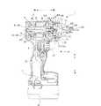
図1に示すように、電子パルスドライバ1は、本体1A及び電池24から構成されている。本体1Aは、ハウジング2と、モータ3と、ハンマ部4と、アンビル部5と、インバータ回路基板6と、制御部7と、回転位置検出素子(ホール素子)8(図2)から主に構成されている。ハウジング2は樹脂製であって電子パルスドライバ1の外郭を成しており、略筒状の胴体部21と、胴体部21から延出されるハンドル部22とから主に構成されている。 As shown in FIG. 1, the
胴体部21内には、その長手方向がモータ3の軸方向と一致するようにモータ3が配置されると共に、モータ3の軸方向一端側に向かってハンマ部4、アンビル部5が並んで配置されている。以下の説明においては、アンビル部5側を前側、モータ3側を後側、モータ3の軸方向と平行な方向を前後方向と定義する。また、胴体部21側を上側、ハンドル部22側を下側、胴体部21からハンドル部22が延びる方向を上下方向と定義する。また、前後方向及び上下方向と直交する方向を左右方向と定義する。 In the
胴体部21内の前側位置には、ハンマ部4及びアンビル部5が内蔵される金属製のハンマケース23が配置されている。ハンマケース23は、前方に向かうに従って徐々に径が細くなる略漏斗形状を成しており、前端部分には開口23aが形成され、開口23aを画成する内壁にはメタル23Aが設けられている。 A
また、胴体部21には、後述のファン32により胴体部21内に外気を吸入・排出する複数の吸気口21a及び排気口21bが形成されている。当該外気によりモータ3は冷却される。 In addition, a plurality of intake ports 21 a and exhaust ports 21 b through which outside air is sucked and discharged into the
ハンドル部22は、胴体部21の前後方向略中央位置から下側に向けて延出され胴体部21と一体に構成されている。そして、ハンドル部22の下端には、モータ3等に電力を供給する電池24が着脱可能に装着されている。ハンドル部22の上部かつ前側位置には、トリガ25が設けられている。また、ハンドル部22の下部の右側側面には、出力トルクに係る後述の規定値を決定するスイッチ26(図3A)が配置されている。このスイッチ26は、表示部26A内に配置されている。このスイッチ26は、一回短い時間押す(短押し、約500msec以下でスイッチ26を押し続けた状態を保つ)ことにより、規定値が、一段階ずつ大きくなり、最大値となったのちに更に短押しすると最小値に戻るように設定されている(出力トルク決定手段)。また表示部26Aには、規定値を表示する7セグメント表示部26Bが設けられている。 The
モータ3は、出力軸部31を有するロータ3Aと、ロータ3Aと対向配置されたステータ3Bとから主に構成されるブラシレスモータであり、出力軸部31の軸方向が前後方向と一致するように胴体部21内に配置されている。出力軸部31は、ロータ3Aの前後に突出しており、その突出した箇所でベアリングにより胴体部21に回転可能に支承されている。出力軸部31の前側に突出している箇所には、出力軸部31と同軸一体回転するファン32が設けられており、更に、当該箇所の最前端位置には、ピニオンギヤ31Aが出力軸部31と同軸一体回転するように設けられている。 The
ハンマ部4は、ギヤ機構41と、ハンマ42とから主に構成されており、ハンマケース23内のモータ3の前側に内蔵されている。ギヤ機構41は、アウターギヤ41Aを有する遊星歯車機構41Bから構成されている。アウターギヤ41Aは、ハンマケース23内に内蔵されると共に胴体部21に固定されている。遊星歯車機構41Bは、アウターギヤ41Aと噛合するようにアウターギヤ41A内に配置されている。 The
ハンマ42は、遊星歯車機構41Bの遊星キャリアの前面に規定されており、前側に向けて突出すると共に遊星歯車機構41Bの遊星キャリアの回転中心からずれた位置に配置された第1係合突起42Aと、遊星歯車機構41Bの遊星キャリアの回転中心を挟んで第1係合突起42Aと対極に位置する図示せぬ第2係合突起とを有している。 The
アンビル部5は、ハンマ部4の前方に配置されており、先端工具装着部51と、アンビル52とから主に構成されている。先端工具装着部51は、円筒状に構成され、ハンマケース23の開口23a内にメタル23Aを介して回転可能に支持されている。先端工具装着部51には、図示せぬビットが挿入される穿孔51aが前後方向へ穿設されており、前端部分には、図示せぬビットを保持するチャック51Aが設けられている。 The
アンビル52は、先端工具装着部51の後方であってハンマケース23内に先端工具装着部51と一体に構成されており、先端工具装着部51の回転中心に対して対極に配置され後側に向けて突出した第1被係合突起52A及び第2被係合突起52Bを有している。ハンマ42が回転すると、第1係合突起42Aと第1被係合突起52Aとが衝突すると同時に、図示せぬ第2係合突起と第2被係合突起52Bとが衝突し、これにより、ハンマ42の回転力がアンビル52に伝達される。 The
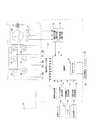
図2に示すように、インバータ回路基板6は、3相ブリッジ形式に接続されたFET等の6個のスイッチング素子Q1〜Q6から構成されている。スイッチング素子Q1〜Q6はインバータ回路基板6に取り付けられ、インバータ回路基板6はモータ3の後端において出力軸部31と略直交するようにモータ3に固定されている。なお、スイッチング素子Q1〜Q6は図1に示すように、その長手方向が出力軸部31と略平行になるようにインバータ回路基板6に取り付けられている。インバータ回路基板6の径方向外側に位置する胴体部21には複数の吸気口21aが設けられている。一方、排気口21bはファン32の径方向外側に位置する胴体部21に設けられている。 As shown in FIG. 2, the
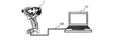
制御部7は、ハンドル部22内の電池24近傍位置に配置された基板に搭載されており、電池24に接続されると共にトリガ25、インバータ回路基板6、図示せぬスイッチ、及び表示部26Aに接続されている。また、図2に示すように、制御部7は、電流検出回路71と、スイッチ操作検出回路72と、印加電圧設定回路73と、回転方向設定回路74と、回転子位置検出回路75と、回転角度検出回路76と、演算部78と、制御信号出力回路79と、表示回路部80と外部接続端子81とを備えている。外部接続端子81は、外部機器であるPC10(図4)を本体1Aに接続するための端子であり、ハンドル部22の電池24に対向する部分に設けられている。PC10の本体1Aへの接続は、電池24を本体1Aから外した状態でのみすることができる。これは、工具使用時に設定変更ができないようにするためである。 The
回転位置検出素子8は、ロータ3Aの永久磁石3Cに対向する位置に設けられており、ロータ3Aの周方向に所定の間隔毎(例えば角度60°毎)に配置されている。 The rotational
次に、モータ3の駆動制御系の構成を図2に基づき説明する。本実施の形態では、モータ3は、3相のブラシレスDCモータであり、ロータ3Aは複数組(本実施の形態では2組)のN極とS極を含む永久磁石を有し、ステータ3Bはスター結線された3相の固定子巻線U、V、Wである。 Next, the configuration of the drive control system of the
インバータ回路基板6の各スイッチング素子Q1〜Q6のゲートは、制御部7の制御信号出力回路79に接続され、各スイッチング素子Q1〜Q6のドレイン又はソースは、ステータ3Bの固定子巻線U、V、Wに接続されている。6個のスイッチング素子Q1〜Q6は、制御信号出力回路79から入力されるスイッチング素子駆動信号によってスイッチング動作を行い、インバータ回路基板6に印加される電池24の直流電圧を3相(U相、V相及びW相)電圧Vu、Vv、Vwとして固定子巻線U、V、Wに電力を供給する。詳細には、制御信号出力回路79から正電源側スイッチング素子Q1、Q2、Q3に入力される出力切替信号H1、H2、H3により、通電される固定子巻線U、V、W、すなわち、ロータ3Aの回転方向が制御される。また、制御信号出力回路79から負電源側スイッチング素子Q4、Q5、Q6に入力されるパルス幅変調信号(PWM信号)H4、H5、H6により、固定子巻線U、V、Wへの電力供給量、すなわち、ロータ3Aの回転速度が制御される。 The gates of the switching elements Q1 to Q6 of the
電流検出回路71は、モータ3に供給される電流値を検出し、演算部78に出力する。スイッチ操作検出回路72は、トリガ25の操作の有無を検出して演算部78に出力する。印加電圧設定回路73は、トリガ25の操作量に応じた信号を演算部78に出力する。 The
また、電子パルスドライバ1には、モータ3の回転方向を切替えるための図示せぬ正逆切替レバーが設けられており、回転方向設定回路74は、正逆切替レバーの切り替えを検出すると、モータ3の回転方向を切り替えるための信号を演算部78に送信する。 Further, the
回転子位置検出回路75は、回転位置検出素子8からの信号に基づきロータ3Aの回転位置を検出し、演算部78に出力する。 The rotor
回転角度検出回路76は、回転子の角度を検出し、回転角度による制御を行なう場合に検出値を用いるためのものである。 The rotation
演算部78は、図示していないが、処理プログラムとデータに基づいて駆動信号を出力するための中央処理装置(CPU)と、データを記憶するための書き換え可能なEEPROM80と、タイマとを備えている。EEPROM80には、締付トルクの基準値として締付トルクの最大値及び最小値と、最大値と最小値との間を所定数等分割して得られる複数の規定値が記憶される。尚規定値の内の最小の規定値は基準値における最小値と同値であり、最大の規定値は基準値における最大値と同値である。これら最大値、最小値、複数の規定値をまとめて設定値と定義する。すなわち、EEPROM80には、締付トルクの最大値及び最小値と、最大値と最小値との間のトルク領域に応じて分割される分割数に応じたトルク値が記憶される。詳細は後述するが、作業者は、締付トルクの最大値及び最小値を設定(決定)し、その後、そのトルク領域を何等分に分割するか(段数)を決定すれば複数の規定値が算出できる。例えば、トルクの最大値5Nm(基準値)、最小値1Nm(基準値)、段数5とした場合を考えると、トルク領域は1〜5であり、等分割数が5であるから、複数の規定値(Nm)は、1、2、3、4、5となる。言い換えると、トルク領域を段数で除した値が複数の規定値の最小値となり、その整数倍が複数の規定値となる。 Although not shown, the
演算部78は、回転方向設定回路74と回転子位置検出回路75からの信号に基づき、出力切替信号H1、H2、H3を、印加電圧設定回路73からの信号に基づきパルス幅変調信号(PWM信号)H4、H5、H6を生成し、制御信号出力回路79に出力する。なお、PWM信号を正電源側スイッチング素子Q1〜Q3に出力し、出力切替信号を負電源側スイッチング素子Q4〜Q6に出力してもよい。 The
また演算部78には前述のスイッチ26が接続されており、スイッチ26の操作により、EEPROM80に記憶された複数の規定値の内の一の規定値が決定される。 Further, the above-described
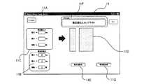
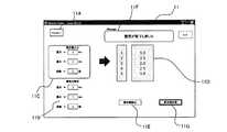
PC10は公知のパソコンであり、図4に示されるように、ケーブル10Aで電子パルスドライバ1と接続されている。PC10においては、図6に示されるように、画面上に動作モード設定ウィンドウ11が表示されている。 The
動作モード設定ウィンドウ11には、コネクトボタン11Aと、既存設定値表示領域11Bと、設定値入力領域11Cと、設定値表示領域11Dと、設定値読込ボタン11Eと、メッセージ表示領域11Fと、設定値送信ボタン11Gとが主に表示されており、上述の動作モードである最大値等の設定値を設定している。コネクトボタン11Aは、PC10と電子パルスドライバ1とがケーブル10Aで接続された後にクリックされることにより、PC10で電子パルスドライバ1を認識している。既存設定値表示領域11Bは、現在工具内のEEPROM80で記憶している設定値を表示している。設定値入力領域11Cは、新たに書き換える設定値を入力する領域である。設定値表示領域11Dは、設定された新たな設定値を表示する領域である。設定値読込ボタン11Eは設定値入力領域11Cに新たな設定値が入力された後にクリックすることにより、入力された値を設定値として認識している。メッセージ表示領域11Fは、動作モード設定ウィンドウ11の諸状態に対する操作者への要求等を表示している。設定値送信ボタン11Gは、クリックされることにより設定値表示領域11Dに表示されている値を電子パルスドライバ1に送信し、EEPROM80に記憶させている。 The operation
上記構成の電子パルスドライバ1及びPC10において、動作モードを設定する工程について図5のフローチャート(基準変更手段)及び動作モード設定ウィンドウ11に基づき説明する。まず、電子パルスドライバ1とPC10とを接続した状態で、S01に進み、コネクトボタン11AをクリックしてEEPROM80に記憶されている設定値を読み込む。S02において電子パルスドライバ1から設定値の返信が無い場合(S02:NO)、具体的には所定時間内(1秒以内)に電子パルスドライバ1が認識されない場合には、S03へ進み、通信異常処理として、メッセージ表示領域11Fに「機器の接続を確信してください」と表示し、S01へと戻る。S02において返信がある場合(S02:YES)には、既存設定値表示領域11BにEEPROM80から読みだした値を表示し、図7のように、メッセージ表示領域11Fに「設定値を入力して下さい」と表示しつつS04へとすすむ。 The steps of setting the operation mode in the
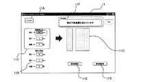
S04では設定値入力領域11Cに最大値を入力し、次にS05へ進んで最小値を入力し、次にS06へ進んで規定値の元になる動作段数を入力する。最大値及び最小値は、10〜1Nmの間で設定可能であり、動作段数は、最大10段である。そしてS07へ進み、設定値読込ボタン11Eをクリックして設定値入力領域11Cに入力された値に基づき、設定値表示領域11Dに表示可能か(設定可能か)を判断する。ここで表示不能(設定不能)と判断された場合(S07:NO)、具体的には、図7、図8に示されるように、設定可能な値より大きな最大値を入力した場合や、最小値より最大値を小さくした場合、或いは最大動作段数を超えて入力した場合には、S08へと進み、メッセージ表示領域11Fに「設定可能範囲を超えています」、「設定値を確認して下さい」と表示し、S06へと戻る。また最大値と最小値とが同値の場合に、“1”以外の値を動作段数として入力すると、メッセージ表示領域11Fに「この場合段数は変更できません」と表示され、段数の表示が“1”に戻される。逆に最大値と最小値とが異なる場合に動作段数を“1”として入力すると、メッセージ表示領域11Fに「設定値は2以上が必要です」と表示され、入力値である“1”は反映されない。 In S04, the maximum value is input to the set
S07で表示可能(設定可能)と判断した場合には、S09へと進み、設定値表示領域11Dに動作段数(本実施の形態では1、2、・・5)及び各段数に対応したトルク値(規定値(図10においては、最大値が3.0Nm、最小値が1.0Nmで最小値と最大値とを含んで5分割した値))を表示する。そしてS10に進み、設定値送信ボタン11Gをクリックすると、図11に示すように、新たに設定した設定値をEEPROM80に送信・記憶させると共に既存設定表示領域11Bに表示し、メッセージ表示領域11Fに「設定が完了しました」と表示して、フローを終了する。 If it is determined in S07 that display is possible (setting is possible), the process proceeds to S09, and the set
設定したトルク値(最大値3.0Nm、最小値1.0Nm、動作段数5)を、電子パルスドライバ1で使用して変更する場合の操作について、以下説明する。なお、各段数に対するトルク値は図11に示すように、段数1で1.0Nm〜段数5で3.0Nmとなるように、1.0Nm〜3.0Nmを5段階に割り振られている。初期状態において、ユーザはスイッチ26を操作する。スイッチ26を一回短押しすると段数1が表示される。その状態でスイッチ26を長押しすると段数1に対応したトルク値1.0Nmが表示される。 The operation when the set torque value (maximum value 3.0 Nm, minimum value 1.0 Nm, number of operation stages 5) is changed by using the
スイッチ26を短押しする毎に段数が1ずつ大きくなり最小数1から最大数5まで変更できる(図3B左側)。ある段数が表示された状態でスイッチ26を長押しすると、各段数に応じて割り振られたトルク値が表示される。トルク値表示後、所定時間(例えば2秒)経過すると段数表示に切り替わる。 Each time the
従って、作業者は、所望の段数(トルク値)になるまでスイッチ26を短押しする。所望の設定値になったらその設定値をEEPROM80に記憶させる。記憶方法は、所望値になったところでスイッチ26の操作を所定時間以上行わない場合に自動的に記憶させることもできるし、スイッチ26を所定操作することで記憶させることもできる。以上により、作業者は所望のトルク値を設定することができる。なお、一通りの作業が完了し、一旦、電池24を外した場合等、設定値をリセットするようにしてもよいし、既存の設定値を保持するようにしてもよい。 Therefore, the operator short-presses the
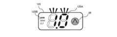
次に本発明の第二の実施の形態について、図12乃至図21に基づき説明する。第二の実施の形態では、外部機器を用いることなく単独で動作モードを変更可能な電動工具について説明する。この電動工具は、図12に示されるように、外部接続端子が無い点、及び図14に示されるように、表示部125以外は第一の実施の形態に係る電子パルスドライバ1と同じであるため、その構成に係る説明は省略する。また第一の実施の形態では、スイッチ26を規定値の選択及び決定の為のみに用いたが、第二の形態では、スイッチ26を、最大値、最小値、規定値からなる設定値の変更の為にも用いる。表示部125は、図14に示されるように、二組の7セグメント表示部125Aと、MIN、MAX、CLTの表示を備える点灯表示部125Bとを有している。 Next, a second embodiment of the present invention will be described with reference to FIGS. In the second embodiment, a power tool capable of changing the operation mode independently without using an external device will be described. This electric tool is the same as the
第二の実施の形態に係る電子パルスドライバにおいて、動作モードを設定する工程について図13の演算部78のフローチャート及び表示部125に基づき説明する。まずスイッチ26を所定時間以上(例えば3秒以上)長押しし、スイッチ26の動作モードを、操作モードから設定モードへと切り換えてスタートする。ここで「操作モード」とは、第一の実施の形態で説明したような、設定された複数の規定値を切り換え、決定するモードであり、「設定モード」とは、設定値を変更するモードである。「操作モード」が第一の操作モードで有り、「設定モード」が第二の操作モードに該当する。 In the electronic pulse driver according to the second embodiment, the step of setting the operation mode will be described based on the flowchart of the
この状態でS101に進み、まず最小値を設定する。上述の3秒以上の長押しにより設定モードに入ると同時に、図15に示されるように、点灯表示部125BにおいてMINが点灯すると共に7セグメント表示部125Aにおいて1.0が点滅し、この状態でS102においてスイッチ26が短押しされると、短押しされる毎に0.1Nmずつ増加する。7セグメント表示部125Aの表示が、図16に示されるように、所定の最小値、例えば2.0Nmに達した後に、S103へ進んでスイッチ26を1秒以上3秒未満で長押しを行ったかを判断する。ここで長押しされていないと判断した場合(S103:NO)には、S104へと進み、トルク値インクリメント処理を行い、S102へと戻る。長押しされていると判断した場合(S103:YES)には、S105へと進み、最小値の設定を終了する。すなわち、スイッチ26の短押しでトルク値を変更し、長押しでトルク値を決定(設定)する。 In this state, the process proceeds to S101, and a minimum value is first set. At the same time as entering the setting mode by the above-mentioned long press for 3 seconds or more, as shown in FIG. 15, MIN is turned on in the
その後S106へと進み、次に最大値を設定する。最小値決定時(S103)におけるスイッチ26の1秒以上の長押しにより、図17に示されるように、点灯表示部125Bにおいて、最小値が表示された状態でMAXが点灯し、7セグメント表示部125Aに表示された最小値(例えば2.0Nm)が点滅する。この状態でS107においてスイッチ26が短押しされると、表示されている最小値である2.0Nmからスイッチ26が押される毎に0.1Nmずつ増加する。7セグメント表示部125Aの表示が、図18に示されるように、所定の最大値(例えば3.0Nm)に達した後に、S108へ進んでスイッチ26を1秒以上3秒未満で長押しを行ったかを判断する。ここで長押しされていないと判断した場合(S108:NO)には、S109へと進み、トルク値インクリメント処理を行い、S107へと戻る。長押しされていると判断した場合(S109:YES)には、S110へと進み、最大値の設定を終了する。ここで、最大値は最小値より大きい値となるため、最大値の設定時に7セグメント表示部125Aに初期値として最小値を表示させることにより、最大値の設定操作をスムーズに行うことができる。 Thereafter, the process proceeds to S106, and then the maximum value is set. When the minimum value is determined (S103), when the
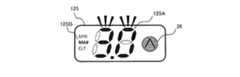
その後S111へと進み、次に動作段数を設定する。最大値決定時(S108)における1秒以上の長押しにより、図19に示されるように、点灯表示部125BにおいてCLTが点灯すると共に7セグメント表示部125Aにおいて1が点滅し、この状態でS112においてスイッチ26が短押しされると、短押しされる毎に動作段数が1ずつ増加する。図20に示されるように、7セグメント表示部125Aの表示が所定の段数、例えば5に達した後に、S113へ進んでスイッチ26を1秒以上3秒未満で長押しを行ったかを判断する。ここで長押しされていないと判断した場合(S113:NO)には、S114へと進み、段数インクリメント処理を行い、S112へと戻る。長押しされていると判断した場合(S113:YES)には、S115へと進み、段数の設定を終了する。 Thereafter, the process proceeds to S111, and then the number of operation stages is set. When the maximum value is determined (S108), the CLT is turned on in the
次にS116へと進み、設定値のレビューを行う。動作段数決定時(S113)における1秒以上の長押しにより、設定値レビューモードに移行する。具体的には、図21に示されるように、所定間隔(例えば0.5秒毎)で点灯表示部125BにおいてMIN、MAX、CLTの順に繰り返し表示されると共に、7セグメント表示部125Aにおいて、点灯表示部125Bで示された表示に対応した設定値が表示される。この状態で、S117へと進み、スイッチ26が押されたか否かを判断する。スイッチ26が押された場合(S117:YES)には、S118へ進み、押されていない場合(S117:NO)には押されるまで待機する。S118において、スイッチ26が長押しされたか否かを判断する。スイッチ26を押した時間が一秒未満の短押しの場合(S118:YES)には、S119へと進み、最小値(2.0Nm)、最大値(3.0Nm)、動作段数(5)の設定を確定して設定モードを終了する。一方、スイッチ26が一秒以上長押しされた場合(S118:NO)には、S101へと戻り、設定をやり直す。なお、S115で動作段数を設定した時点で各値を確定し設定モードを終了してもよい。 Next, the process proceeds to S116 to review the set value. When the operation stage number is determined (S113), the setting value review mode is entered by long pressing for 1 second or longer. Specifically, as shown in FIG. 21, the
第一の実施の形態及び第二の実施の形態のいずれにおいても、締付トルクの設定範囲を変更することができるため、一の工具で幅広い締付トルクに対応することができる。特に第一の実施の形態では、外部機器であるPCにより、電動工具である電子パルスドライバの設定を行うため、作業者が設定値を不意に変更することを抑制することができる。また第二の実施の形態では、外部機器を必要としないため、設定値の変更が容易であり、必要に応じて設定値を容易に変更することができる。 In both the first embodiment and the second embodiment, since the setting range of the tightening torque can be changed, a single tool can cope with a wide range of tightening torque. In particular, in the first embodiment, since an electronic pulse driver that is an electric tool is set by a PC that is an external device, it is possible to prevent the operator from changing the setting value unexpectedly. In the second embodiment, since no external device is required, the setting value can be easily changed, and the setting value can be easily changed as necessary.
本発明の電動工具及び電動工具の動作モード変更システムは、上述の実施の形態に限定されず特許請求の範囲に記載された範囲で種々の改良や変形が可能である。例えば、第二の実施の形態においては、電動工具のみで設定を行うため、電池の残量が少ないときは設定がうまく行えないことがある。よって制御部に電池の残量を検出する電池残量検出回路を設け、電池残量検出回路の検出結果に応じて設定不能にするようにしてもよい。 The power tool and the power tool operation mode change system of the present invention are not limited to the above-described embodiments, and various improvements and modifications can be made within the scope described in the claims. For example, in the second embodiment, since the setting is performed only with the electric tool, the setting may not be performed well when the remaining battery level is low. Therefore, a battery remaining amount detection circuit for detecting the remaining amount of the battery may be provided in the control unit so that the setting cannot be made according to the detection result of the battery remaining amount detection circuit.
また外部機器としては汎用品であるPCについて述べているが、これに限らず、動作モード変更専用の機器であってもよい。また第二の実施の形態では、スイッチ26で操作モードと変更モードとのいずれも実施したが、これに限らず、それぞれ専用の操作部が存在してもよい。 Further, although the PC as a general-purpose product is described as the external device, the present invention is not limited to this, and a device dedicated to changing the operation mode may be used. In the second embodiment, both the operation mode and the change mode are performed by the
また、上記した実施の形態では電動工具として電子パルスドライバを用いて説明したが、これに限らず、モータにより先端工具が回転する工具、例えばドライバドリル、であってもよい。 In the above-described embodiment, the electronic pulse driver is used as the power tool. However, the present invention is not limited to this, and a tool whose tip tool is rotated by a motor, for example, a driver drill, may be used.
また、用途としては、分電盤の締め付け、電子機器の組み立て、自動車工場での組み立て等、様々な作業に適用することができる。 Moreover, as an application, it can apply to various operations, such as fastening of a distribution board, the assembly of an electronic device, the assembly in a motor vehicle factory.
また、第二の実施の形態の電動工具であっても、第一の実施の形態のように外部機器に接続可能に構成されていてもよい。これにより、電動工具本体及び外部機器の両方で動作モードを変更することができる。 Further, even the electric power tool of the second embodiment may be configured to be connectable to an external device as in the first embodiment. Thereby, an operation mode can be changed with both an electric tool main body and an external apparatus.
1:電子パルスドライバ 1A:本体 2:ハウジング 3:モータ 3A:ロータ
3B:ステータ 3C:永久磁石 4:ギヤ部 5:アンビル部 6:インバータ回路
7:制御部 8:回転位置検出素子 10:PC 10A:ケーブル
11:動作モード設定ウィンドウ 11A:コネクトボタン
11B:既存設定値表示領域 11C:設定値入力領域 11D:設定値表示領域
11E:設定値読込ボタン 11F:メッセージ表示領域 11G:設定値送信ボタン
21:胴体部 21a:吸気口 21b:排気口 22:ハンドル部
23:ハンマケース 23A:メタル 23a:開口 24:電池 25:トリガ
26:スイッチ 31:出力軸部 31A:ピニオンギヤ 32:ファン
41:ギヤ機構 41A:アウターギヤ 41B:遊星歯車機構 41B:遊星歯車機構
51:先端工具装着部 51A:チャック 51a:穿孔 52:アンビル
66:インバータ回路 71:電流検出回路 72:スイッチ操作検出回路
73:印加電圧設定回路 74:回転方向設定回路 75:回転子位置検出回路
76:回転角度検出回路 78:演算部 79:制御信号出力回路
80:表示回路部 81:外部接続端子 125:表示部
125A:7セグメント表示部 125B:点灯表示部
1: Electronic pulse driver 1A: Main body 2: Housing 3:
73: Applied voltage setting circuit 74: Rotation direction setting circuit 75: Rotor position detection circuit 76: Rotation angle detection circuit 78: Calculation unit 79: Control signal output circuit 80: Display circuit unit 81: External connection terminal 125:
Claims (11)
Translated fromJapanese該先端工具装着部を回転駆動するモータと、
該モータの駆動を制御する制御部と、を備え、
前記モータの動作に影響を与える既定値の範囲または分割数を任意に設定可能としたことを特徴とする電動工具。A tip tool mounting portion on which the tip tool is mounted;
A motor for rotationally driving the tip tool mounting portion;
A control unit for controlling the driving of the motor,
A power tool characterized in that a predetermined range or number of divisions affecting the operation of the motor can be arbitrarily set.
該出力設定部は、前記既定値の最小値及び最大値、または、該最大値と該最小値で規定される範囲の分割数を任意に設定可能であることを特徴とする請求項1に記載の電動工具。An output setting unit for setting the output condition of the motor;
The output setting unit can arbitrarily set a minimum value and a maximum value of the predetermined value, or a division number of a range defined by the maximum value and the minimum value. Power tools.
前記外部機器接続部に接続可能な外部機器と、
を備えた電動工具システムであって、
該外部機器は、前記既定値の最小値及び最大値、または、該最大値と該最小値で規定される範囲の分割数を任意に設定可能であることを特徴とする電動工具システム。The power tool according to claim 1 or 2, further comprising an external device connection unit connected to the control unit,
An external device connectable to the external device connection unit;
An electric tool system comprising:
The electric tool system characterized in that the external device can arbitrarily set the minimum value and the maximum value of the predetermined value or the number of divisions in a range defined by the maximum value and the minimum value.
該先端工具装着部を回転駆動するモータと、
該モータの駆動を制御する制御部と、
該制御部に接続され該モータの駆動状態を変更可能なスイッチ部と、
外部機器に接続される外部機器接続部と、を備え、
該制御部は、該モータが出力するトルクの基準値と該基準値に応じて規定される複数の規定値とを記憶する記憶手段と、該複数の規定値の内の一の規定値を該スイッチ部の操作により決定する出力トルク決定手段とを備え、
該記憶手段は、該基準値及び該複数の規定値を該外部機器接続部に接続された該外部機器が有する基準変更手段により変更可能に構成されていることを特徴とする電動工具。A tip tool mounting portion on which the tip tool is mounted;
A motor for rotationally driving the tip tool mounting portion;
A control unit for controlling the driving of the motor;
A switch unit connected to the control unit and capable of changing a driving state of the motor;
An external device connection part connected to the external device,
The control unit stores a reference value of torque output by the motor and a plurality of specified values specified according to the reference value, and stores one specified value among the plurality of specified values. Output torque determining means determined by operation of the switch unit,
The storage means is configured to be able to change the reference value and the plurality of specified values by reference changing means included in the external device connected to the external device connection unit.
該先端工具装着部を回転駆動するモータと、
該モータの駆動を制御する制御部と、
該制御部に接続され該モータの駆動状態を変更可能であり、少なくとも第一操作モードと第二の操作モードとを有するスイッチ部と、を備え、
該制御部は、該モータが出力するトルクの基準値に応じて規定される複数の規定値の内の一の規定値を該スイッチ部の該第一の操作モードにより決定する出力トルク決定手段と、該基準値及び該複数の規定値を、該スイッチ部の該第二の操作モードにより変更する基準変更手段と、を有することを特徴とする電動工具。A tip tool mounting portion on which the tip tool is mounted;
A motor for rotationally driving the tip tool mounting portion;
A control unit for controlling the driving of the motor;
A switch unit connected to the control unit and capable of changing a driving state of the motor, and having at least a first operation mode and a second operation mode;
The control unit includes an output torque determining unit that determines one specified value among a plurality of specified values defined in accordance with a reference value of torque output from the motor by the first operation mode of the switch unit. And a reference changing means for changing the reference value and the plurality of specified values in accordance with the second operation mode of the switch unit.
該制御装置は、該電池の残量に応じて該基準値変更手段の設定を不能にする設定不能手段を備えることを特徴とする請求項5に記載の電動工具。A battery for supplying electric power for driving the motor;
6. The power tool according to claim 5, wherein the control device includes a setting disable unit that disables the setting of the reference value changing unit according to the remaining amount of the battery.
該外部機器接続部に接続可能な外部機器と、を備え、
該制御部は、該モータが出力するトルクの基準値と該基準値に応じて規定される複数の規定値とを記憶する記憶手段と、該複数の規定値の内の一の規定値を該スイッチ部の操作により決定する出力トルク決定手段とを有し、
該外部機器は、該外部機器接続部に接続された状態で、該記憶手段に記憶された該基準値及び該複数の規定値を変更可能な基準変更手段を有することを特徴とする電動工具システム。
A tip tool mounting portion on which a tip tool is mounted, a motor that rotationally drives the tip tool mounting portion, a control unit that controls driving of the motor, and a drive state of the motor that is connected to the control unit can be changed An electric tool comprising a switch unit and an external device connection unit;
An external device connectable to the external device connection unit,
The control unit stores a reference value of torque output by the motor and a plurality of specified values specified according to the reference value, and stores one specified value among the plurality of specified values. Output torque determining means determined by operation of the switch unit,
The external device includes an electric tool system having reference changing means capable of changing the reference value and the plurality of specified values stored in the storage means while being connected to the external device connecting portion. .
Priority Applications (4)
| Application Number | Priority Date | Filing Date | Title |
|---|---|---|---|
| JP2012052457AJP2013184266A (en) | 2012-03-09 | 2012-03-09 | Power tool and power tool system |
| US13/752,207US20130233584A1 (en) | 2012-03-09 | 2013-01-28 | Power Tool and Power Tool System |
| DE102013101308ADE102013101308A1 (en) | 2012-03-09 | 2013-02-11 | Power tool and power tool system |
| CN2013100536264ACN103302642A (en) | 2012-03-09 | 2013-02-19 | Power tool and power tool system |
Applications Claiming Priority (1)
| Application Number | Priority Date | Filing Date | Title |
|---|---|---|---|
| JP2012052457AJP2013184266A (en) | 2012-03-09 | 2012-03-09 | Power tool and power tool system |
Publications (1)
| Publication Number | Publication Date |
|---|---|
| JP2013184266Atrue JP2013184266A (en) | 2013-09-19 |
Family
ID=49029678
Family Applications (1)
| Application Number | Title | Priority Date | Filing Date |
|---|---|---|---|
| JP2012052457APendingJP2013184266A (en) | 2012-03-09 | 2012-03-09 | Power tool and power tool system |
Country Status (4)
| Country | Link |
|---|---|
| US (1) | US20130233584A1 (en) |
| JP (1) | JP2013184266A (en) |
| CN (1) | CN103302642A (en) |
| DE (1) | DE102013101308A1 (en) |
Cited By (9)
| Publication number | Priority date | Publication date | Assignee | Title |
|---|---|---|---|---|
| WO2015182602A1 (en)* | 2014-05-26 | 2015-12-03 | 株式会社マキタ | Device for power tool |
| CN104516367B (en)* | 2013-09-26 | 2017-02-22 | 南京德朔实业有限公司 | Electric tool and threaded piece fastening degree control method |
| CN107283369A (en)* | 2016-04-12 | 2017-10-24 | 罗伯特·博世有限公司 | Hand held power machine with electronic type torque limiter |
| JP2017210953A (en)* | 2016-03-02 | 2017-11-30 | センブレ エス.ピー.エー. | Hydraulic pump for hydrodynamic compression tool |
| WO2018088443A1 (en)* | 2016-11-10 | 2018-05-17 | 日東工器株式会社 | Electric tool, and control device and control circuit for same |
| WO2022154056A1 (en)* | 2021-01-15 | 2022-07-21 | 工機ホールディングス株式会社 | Work machine |
| US11712741B2 (en) | 2012-01-30 | 2023-08-01 | Black & Decker Inc. | Remote programming of a power tool |
| US12044530B2 (en) | 2008-07-10 | 2024-07-23 | Black & Decker Inc. | Communication protocol for remotely controlled laser devices |
| US12318906B2 (en) | 2012-06-08 | 2025-06-03 | Black & Decker Inc. | Power tool having multiple operating modes |
Families Citing this family (17)
| Publication number | Priority date | Publication date | Assignee | Title |
|---|---|---|---|---|
| DE102013222550B4 (en)* | 2013-11-06 | 2024-12-19 | Robert Bosch Gmbh | hand tool machine |
| KR102074052B1 (en)* | 2015-06-02 | 2020-02-05 | 밀워키 일렉트릭 툴 코포레이션 | Multi-speed power tools with electronic clutch |
| DE102015211700A1 (en)* | 2015-06-24 | 2016-12-29 | Robert Bosch Gmbh | Hand tool |
| JP6533186B2 (en)* | 2016-05-13 | 2019-06-19 | ミネベアミツミ株式会社 | Motor drive control device and motor drive control method |
| CN108081216A (en)* | 2016-11-21 | 2018-05-29 | 车王电子股份有限公司 | Electric tool and control method thereof |
| JP6868851B2 (en)* | 2017-01-31 | 2021-05-12 | パナソニックIpマネジメント株式会社 | Impact rotary tool |
| CN107816317B (en)* | 2017-11-22 | 2019-02-22 | 中国矿业大学 | A high-voltage electric pulse and mechanical drill synergistic rapid drilling device and method |
| EP3501740A1 (en)* | 2017-12-20 | 2019-06-26 | HILTI Aktiengesellschaft | Setting method for threaded connection by means of impact wrench |
| US11318589B2 (en)* | 2018-02-19 | 2022-05-03 | Milwaukee Electric Tool Corporation | Impact tool |
| TWI733067B (en) | 2018-12-06 | 2021-07-11 | 優鋼機械股份有限公司 | Setting method of electronic torque tool |
| EP3894136A4 (en)* | 2018-12-10 | 2023-01-11 | Milwaukee Electric Tool Corporation | HIGH TORQUE IMPACT TOOL |
| EP3898101A4 (en)* | 2018-12-21 | 2022-11-30 | Milwaukee Electric Tool Corporation | HIGH TORQUE IMPACT TOOL |
| JP7386027B2 (en)* | 2019-09-27 | 2023-11-24 | 株式会社マキタ | rotary impact tool |
| JP7320419B2 (en) | 2019-09-27 | 2023-08-03 | 株式会社マキタ | rotary impact tool |
| US12157208B2 (en) | 2020-02-24 | 2024-12-03 | Milwaukee Electric Tool Corporation | Impact tool |
| USD948978S1 (en) | 2020-03-17 | 2022-04-19 | Milwaukee Electric Tool Corporation | Rotary impact wrench |
| TWI748510B (en)* | 2020-06-10 | 2021-12-01 | 朝程工業股份有限公司 | Operation mode switching device and operation mode switching device of electric tool |
Citations (9)
| Publication number | Priority date | Publication date | Assignee | Title |
|---|---|---|---|---|
| JPH0511803A (en)* | 1991-07-08 | 1993-01-22 | Matsushita Electric Ind Co Ltd | Motor controller parameter setter |
| JP2000061858A (en)* | 1998-08-18 | 2000-02-29 | Nippon Denki Denpa Kiki Engineering Kk | Torque driver |
| JP2002305037A (en)* | 2001-04-05 | 2002-10-18 | Makita Corp | Battery-type power tool |
| JP2005324265A (en)* | 2004-05-12 | 2005-11-24 | Matsushita Electric Works Ltd | Impact rotary tool |
| JP2008197859A (en)* | 2007-02-13 | 2008-08-28 | Brother Ind Ltd | Numerical control device, control program, and storage medium |
| JP2008213052A (en)* | 2007-02-28 | 2008-09-18 | Matsushita Electric Works Ltd | Power tool |
| JP2012030325A (en)* | 2010-07-30 | 2012-02-16 | Hitachi Koki Co Ltd | Electric power tool, and electric power tool for fastening thread |
| JP2012139800A (en)* | 2011-01-05 | 2012-07-26 | Makita Corp | Electric power tool |
| JP2012139801A (en)* | 2011-01-05 | 2012-07-26 | Makita Corp | Electric tool |
Family Cites Families (11)
| Publication number | Priority date | Publication date | Assignee | Title |
|---|---|---|---|---|
| EP1769887B1 (en)* | 2000-03-16 | 2008-07-30 | Makita Corporation | Power tools |
| JP3533650B2 (en)* | 2002-05-31 | 2004-05-31 | ホーコス株式会社 | Drilling control method |
| US7182147B2 (en)* | 2002-06-27 | 2007-02-27 | Snap-On Incorporated | Tool apparatus, system and method of use |
| JP4329369B2 (en)* | 2003-03-20 | 2009-09-09 | パナソニック電工株式会社 | Power tool usage support method and apparatus |
| JP2005118910A (en)* | 2003-10-14 | 2005-05-12 | Matsushita Electric Works Ltd | Impact rotary tool |
| JP5056012B2 (en)* | 2004-07-13 | 2012-10-24 | 株式会社安川電機 | Electric motor control device |
| JP4339275B2 (en)* | 2005-05-12 | 2009-10-07 | 株式会社エスティック | Method and apparatus for controlling impact type screw fastening device |
| JP5115904B2 (en)* | 2007-09-21 | 2013-01-09 | 日立工機株式会社 | Impact tools |
| EP2177322B1 (en)* | 2008-10-20 | 2014-05-07 | CEKA Elektrowerkzeuge AG + Co. KG | Tool unit for an electrical tool, electrical tool and method for operating same |
| JP5440766B2 (en) | 2009-07-29 | 2014-03-12 | 日立工機株式会社 | Impact tools |
| US8674640B2 (en)* | 2011-01-05 | 2014-03-18 | Makita Corporation | Electric power tool |
- 2012
- 2012-03-09JPJP2012052457Apatent/JP2013184266A/enactivePending
- 2013
- 2013-01-28USUS13/752,207patent/US20130233584A1/ennot_activeAbandoned
- 2013-02-11DEDE102013101308Apatent/DE102013101308A1/ennot_activeWithdrawn
- 2013-02-19CNCN2013100536264Apatent/CN103302642A/enactivePending
Patent Citations (9)
| Publication number | Priority date | Publication date | Assignee | Title |
|---|---|---|---|---|
| JPH0511803A (en)* | 1991-07-08 | 1993-01-22 | Matsushita Electric Ind Co Ltd | Motor controller parameter setter |
| JP2000061858A (en)* | 1998-08-18 | 2000-02-29 | Nippon Denki Denpa Kiki Engineering Kk | Torque driver |
| JP2002305037A (en)* | 2001-04-05 | 2002-10-18 | Makita Corp | Battery-type power tool |
| JP2005324265A (en)* | 2004-05-12 | 2005-11-24 | Matsushita Electric Works Ltd | Impact rotary tool |
| JP2008197859A (en)* | 2007-02-13 | 2008-08-28 | Brother Ind Ltd | Numerical control device, control program, and storage medium |
| JP2008213052A (en)* | 2007-02-28 | 2008-09-18 | Matsushita Electric Works Ltd | Power tool |
| JP2012030325A (en)* | 2010-07-30 | 2012-02-16 | Hitachi Koki Co Ltd | Electric power tool, and electric power tool for fastening thread |
| JP2012139800A (en)* | 2011-01-05 | 2012-07-26 | Makita Corp | Electric power tool |
| JP2012139801A (en)* | 2011-01-05 | 2012-07-26 | Makita Corp | Electric tool |
Cited By (20)
| Publication number | Priority date | Publication date | Assignee | Title |
|---|---|---|---|---|
| US12044530B2 (en) | 2008-07-10 | 2024-07-23 | Black & Decker Inc. | Communication protocol for remotely controlled laser devices |
| US11712741B2 (en) | 2012-01-30 | 2023-08-01 | Black & Decker Inc. | Remote programming of a power tool |
| US12318906B2 (en) | 2012-06-08 | 2025-06-03 | Black & Decker Inc. | Power tool having multiple operating modes |
| CN104516367B (en)* | 2013-09-26 | 2017-02-22 | 南京德朔实业有限公司 | Electric tool and threaded piece fastening degree control method |
| WO2015182602A1 (en)* | 2014-05-26 | 2015-12-03 | 株式会社マキタ | Device for power tool |
| JP2015223638A (en)* | 2014-05-26 | 2015-12-14 | 株式会社マキタ | Electric tool equipment |
| US10074267B2 (en) | 2014-05-26 | 2018-09-11 | Makita Corporation | Apparatus for electric power tool |
| JP2017210953A (en)* | 2016-03-02 | 2017-11-30 | センブレ エス.ピー.エー. | Hydraulic pump for hydrodynamic compression tool |
| CN107283369A (en)* | 2016-04-12 | 2017-10-24 | 罗伯特·博世有限公司 | Hand held power machine with electronic type torque limiter |
| KR20190073503A (en)* | 2016-11-10 | 2019-06-26 | 니토 코키 가부시키가이샤 | Power tools and their control and control circuits |
| CN109922927A (en)* | 2016-11-10 | 2019-06-21 | 日东工器株式会社 | Electric tool and its control device and control circuit |
| GB2569764A (en)* | 2016-11-10 | 2019-06-26 | Nitto Kohki Co | Electric tool, and control device and control circuit for same |
| KR102191641B1 (en) | 2016-11-10 | 2020-12-16 | 니토 코키 가부시키가이샤 | Electric Motor-Driven Tool, and Control Device and Control Circuit Therefor |
| CN109922927B (en)* | 2016-11-10 | 2020-12-22 | 日东工器株式会社 | Electric tool and its control device and control circuit |
| US11077539B2 (en) | 2016-11-10 | 2021-08-03 | Nitto Kohki Co., Ltd. | Electric motor-driven tool, and control device and control circuit therefor |
| GB2569764B (en)* | 2016-11-10 | 2022-01-12 | Nitto Kohki Co | Electric motor-driven tool, and control device and control circuit therefor |
| TWI648132B (en)* | 2016-11-10 | 2019-01-21 | Nitto Kohki Co., Ltd. | Electric tool, control device and control circuit thereof |
| JPWO2018088443A1 (en)* | 2016-11-10 | 2018-11-08 | 日東工器株式会社 | Electric tool, control device and control circuit thereof |
| WO2018088443A1 (en)* | 2016-11-10 | 2018-05-17 | 日東工器株式会社 | Electric tool, and control device and control circuit for same |
| WO2022154056A1 (en)* | 2021-01-15 | 2022-07-21 | 工機ホールディングス株式会社 | Work machine |
Also Published As
| Publication number | Publication date |
|---|---|
| DE102013101308A1 (en) | 2013-09-12 |
| US20130233584A1 (en) | 2013-09-12 |
| CN103302642A (en) | 2013-09-18 |
Similar Documents
| Publication | Publication Date | Title |
|---|---|---|
| JP2013184266A (en) | Power tool and power tool system | |
| WO2012160799A2 (en) | Power tool | |
| US11161227B2 (en) | Electric working machine and method for controlling motor of electric working machine | |
| EP2474391B1 (en) | Electric power tool | |
| JP5824419B2 (en) | Electric tool | |
| JP5800761B2 (en) | Electric tool | |
| JP5995064B2 (en) | Power equipment and power equipment system | |
| US20140158390A1 (en) | Electric tool | |
| JP5464434B2 (en) | Electric tool | |
| JP6380933B2 (en) | Electric tool | |
| JP5696885B2 (en) | Electric tool | |
| JP7540557B2 (en) | Work Machine | |
| CN102356540A (en) | Power tool | |
| WO2013187411A1 (en) | Power-driven device, power-driven-device system, and electric-power-tool management system | |
| JP2012240165A (en) | Power tool | |
| JP2014018868A (en) | Electric tool management system | |
| JP2011020230A (en) | Portable tool | |
| US20230107745A1 (en) | Technique for controlling motor in electric power tool | |
| EP4059663B1 (en) | Impact tool, and method and program for controlling impact tool | |
| US20230271310A1 (en) | Electrical equipment and electrical equipment system | |
| JP2014061579A (en) | Electric power tool | |
| JP2014124763A (en) | Electric power tool | |
| WO2022070760A1 (en) | Work machine | |
| JP5464433B2 (en) | Electric tool | |
| JP5472736B2 (en) | Electric tool |
Legal Events
| Date | Code | Title | Description |
|---|---|---|---|
| A621 | Written request for application examination | Free format text:JAPANESE INTERMEDIATE CODE: A621 Effective date:20140930 | |
| A977 | Report on retrieval | Free format text:JAPANESE INTERMEDIATE CODE: A971007 Effective date:20150529 | |
| A131 | Notification of reasons for refusal | Free format text:JAPANESE INTERMEDIATE CODE: A131 Effective date:20150604 | |
| A02 | Decision of refusal | Free format text:JAPANESE INTERMEDIATE CODE: A02 Effective date:20151029 |