JP2013183619A - Power supply system - Google Patents
Power supply systemDownload PDFInfo
- Publication number
- JP2013183619A JP2013183619AJP2012048181AJP2012048181AJP2013183619AJP 2013183619 AJP2013183619 AJP 2013183619AJP 2012048181 AJP2012048181 AJP 2012048181AJP 2012048181 AJP2012048181 AJP 2012048181AJP 2013183619 AJP2013183619 AJP 2013183619A
- Authority
- JP
- Japan
- Prior art keywords
- voltage
- fuel cell
- power supply
- mode
- vehicle
- Prior art date
- Legal status (The legal status is an assumption and is not a legal conclusion. Google has not performed a legal analysis and makes no representation as to the accuracy of the status listed.)
- Granted
Links
Images


Classifications
- B—PERFORMING OPERATIONS; TRANSPORTING
- B60—VEHICLES IN GENERAL
- B60L—PROPULSION OF ELECTRICALLY-PROPELLED VEHICLES; SUPPLYING ELECTRIC POWER FOR AUXILIARY EQUIPMENT OF ELECTRICALLY-PROPELLED VEHICLES; ELECTRODYNAMIC BRAKE SYSTEMS FOR VEHICLES IN GENERAL; MAGNETIC SUSPENSION OR LEVITATION FOR VEHICLES; MONITORING OPERATING VARIABLES OF ELECTRICALLY-PROPELLED VEHICLES; ELECTRIC SAFETY DEVICES FOR ELECTRICALLY-PROPELLED VEHICLES
- B60L55/00—Arrangements for supplying energy stored within a vehicle to a power network, i.e. vehicle-to-grid [V2G] arrangements
- B—PERFORMING OPERATIONS; TRANSPORTING
- B60—VEHICLES IN GENERAL
- B60L—PROPULSION OF ELECTRICALLY-PROPELLED VEHICLES; SUPPLYING ELECTRIC POWER FOR AUXILIARY EQUIPMENT OF ELECTRICALLY-PROPELLED VEHICLES; ELECTRODYNAMIC BRAKE SYSTEMS FOR VEHICLES IN GENERAL; MAGNETIC SUSPENSION OR LEVITATION FOR VEHICLES; MONITORING OPERATING VARIABLES OF ELECTRICALLY-PROPELLED VEHICLES; ELECTRIC SAFETY DEVICES FOR ELECTRICALLY-PROPELLED VEHICLES
- B60L58/00—Methods or circuit arrangements for monitoring or controlling batteries or fuel cells, specially adapted for electric vehicles
- B60L58/10—Methods or circuit arrangements for monitoring or controlling batteries or fuel cells, specially adapted for electric vehicles for monitoring or controlling batteries
- B—PERFORMING OPERATIONS; TRANSPORTING
- B60—VEHICLES IN GENERAL
- B60L—PROPULSION OF ELECTRICALLY-PROPELLED VEHICLES; SUPPLYING ELECTRIC POWER FOR AUXILIARY EQUIPMENT OF ELECTRICALLY-PROPELLED VEHICLES; ELECTRODYNAMIC BRAKE SYSTEMS FOR VEHICLES IN GENERAL; MAGNETIC SUSPENSION OR LEVITATION FOR VEHICLES; MONITORING OPERATING VARIABLES OF ELECTRICALLY-PROPELLED VEHICLES; ELECTRIC SAFETY DEVICES FOR ELECTRICALLY-PROPELLED VEHICLES
- B60L58/00—Methods or circuit arrangements for monitoring or controlling batteries or fuel cells, specially adapted for electric vehicles
- B60L58/30—Methods or circuit arrangements for monitoring or controlling batteries or fuel cells, specially adapted for electric vehicles for monitoring or controlling fuel cells
- B—PERFORMING OPERATIONS; TRANSPORTING
- B60—VEHICLES IN GENERAL
- B60R—VEHICLES, VEHICLE FITTINGS, OR VEHICLE PARTS, NOT OTHERWISE PROVIDED FOR
- B60R16/00—Electric or fluid circuits specially adapted for vehicles and not otherwise provided for; Arrangement of elements of electric or fluid circuits specially adapted for vehicles and not otherwise provided for
- B60R16/02—Electric or fluid circuits specially adapted for vehicles and not otherwise provided for; Arrangement of elements of electric or fluid circuits specially adapted for vehicles and not otherwise provided for electric constitutive elements
- B60R16/03—Electric or fluid circuits specially adapted for vehicles and not otherwise provided for; Arrangement of elements of electric or fluid circuits specially adapted for vehicles and not otherwise provided for electric constitutive elements for supply of electrical power to vehicle subsystems or for
- B60R16/033—Electric or fluid circuits specially adapted for vehicles and not otherwise provided for; Arrangement of elements of electric or fluid circuits specially adapted for vehicles and not otherwise provided for electric constitutive elements for supply of electrical power to vehicle subsystems or for characterised by the use of electrical cells or batteries
- Y—GENERAL TAGGING OF NEW TECHNOLOGICAL DEVELOPMENTS; GENERAL TAGGING OF CROSS-SECTIONAL TECHNOLOGIES SPANNING OVER SEVERAL SECTIONS OF THE IPC; TECHNICAL SUBJECTS COVERED BY FORMER USPC CROSS-REFERENCE ART COLLECTIONS [XRACs] AND DIGESTS
- Y02—TECHNOLOGIES OR APPLICATIONS FOR MITIGATION OR ADAPTATION AGAINST CLIMATE CHANGE
- Y02E—REDUCTION OF GREENHOUSE GAS [GHG] EMISSIONS, RELATED TO ENERGY GENERATION, TRANSMISSION OR DISTRIBUTION
- Y02E60/00—Enabling technologies; Technologies with a potential or indirect contribution to GHG emissions mitigation
- Y02E60/30—Hydrogen technology
- Y02E60/50—Fuel cells
- Y—GENERAL TAGGING OF NEW TECHNOLOGICAL DEVELOPMENTS; GENERAL TAGGING OF CROSS-SECTIONAL TECHNOLOGIES SPANNING OVER SEVERAL SECTIONS OF THE IPC; TECHNICAL SUBJECTS COVERED BY FORMER USPC CROSS-REFERENCE ART COLLECTIONS [XRACs] AND DIGESTS
- Y02—TECHNOLOGIES OR APPLICATIONS FOR MITIGATION OR ADAPTATION AGAINST CLIMATE CHANGE
- Y02T—CLIMATE CHANGE MITIGATION TECHNOLOGIES RELATED TO TRANSPORTATION
- Y02T10/00—Road transport of goods or passengers
- Y02T10/60—Other road transportation technologies with climate change mitigation effect
- Y02T10/70—Energy storage systems for electromobility, e.g. batteries
- Y—GENERAL TAGGING OF NEW TECHNOLOGICAL DEVELOPMENTS; GENERAL TAGGING OF CROSS-SECTIONAL TECHNOLOGIES SPANNING OVER SEVERAL SECTIONS OF THE IPC; TECHNICAL SUBJECTS COVERED BY FORMER USPC CROSS-REFERENCE ART COLLECTIONS [XRACs] AND DIGESTS
- Y02—TECHNOLOGIES OR APPLICATIONS FOR MITIGATION OR ADAPTATION AGAINST CLIMATE CHANGE
- Y02T—CLIMATE CHANGE MITIGATION TECHNOLOGIES RELATED TO TRANSPORTATION
- Y02T10/00—Road transport of goods or passengers
- Y02T10/60—Other road transportation technologies with climate change mitigation effect
- Y02T10/7072—Electromobility specific charging systems or methods for batteries, ultracapacitors, supercapacitors or double-layer capacitors
- Y—GENERAL TAGGING OF NEW TECHNOLOGICAL DEVELOPMENTS; GENERAL TAGGING OF CROSS-SECTIONAL TECHNOLOGIES SPANNING OVER SEVERAL SECTIONS OF THE IPC; TECHNICAL SUBJECTS COVERED BY FORMER USPC CROSS-REFERENCE ART COLLECTIONS [XRACs] AND DIGESTS
- Y02—TECHNOLOGIES OR APPLICATIONS FOR MITIGATION OR ADAPTATION AGAINST CLIMATE CHANGE
- Y02T—CLIMATE CHANGE MITIGATION TECHNOLOGIES RELATED TO TRANSPORTATION
- Y02T90/00—Enabling technologies or technologies with a potential or indirect contribution to GHG emissions mitigation
- Y02T90/10—Technologies relating to charging of electric vehicles
- Y02T90/12—Electric charging stations
- Y—GENERAL TAGGING OF NEW TECHNOLOGICAL DEVELOPMENTS; GENERAL TAGGING OF CROSS-SECTIONAL TECHNOLOGIES SPANNING OVER SEVERAL SECTIONS OF THE IPC; TECHNICAL SUBJECTS COVERED BY FORMER USPC CROSS-REFERENCE ART COLLECTIONS [XRACs] AND DIGESTS
- Y02—TECHNOLOGIES OR APPLICATIONS FOR MITIGATION OR ADAPTATION AGAINST CLIMATE CHANGE
- Y02T—CLIMATE CHANGE MITIGATION TECHNOLOGIES RELATED TO TRANSPORTATION
- Y02T90/00—Enabling technologies or technologies with a potential or indirect contribution to GHG emissions mitigation
- Y02T90/10—Technologies relating to charging of electric vehicles
- Y02T90/14—Plug-in electric vehicles
- Y—GENERAL TAGGING OF NEW TECHNOLOGICAL DEVELOPMENTS; GENERAL TAGGING OF CROSS-SECTIONAL TECHNOLOGIES SPANNING OVER SEVERAL SECTIONS OF THE IPC; TECHNICAL SUBJECTS COVERED BY FORMER USPC CROSS-REFERENCE ART COLLECTIONS [XRACs] AND DIGESTS
- Y02—TECHNOLOGIES OR APPLICATIONS FOR MITIGATION OR ADAPTATION AGAINST CLIMATE CHANGE
- Y02T—CLIMATE CHANGE MITIGATION TECHNOLOGIES RELATED TO TRANSPORTATION
- Y02T90/00—Enabling technologies or technologies with a potential or indirect contribution to GHG emissions mitigation
- Y02T90/10—Technologies relating to charging of electric vehicles
- Y02T90/16—Information or communication technologies improving the operation of electric vehicles
- Y—GENERAL TAGGING OF NEW TECHNOLOGICAL DEVELOPMENTS; GENERAL TAGGING OF CROSS-SECTIONAL TECHNOLOGIES SPANNING OVER SEVERAL SECTIONS OF THE IPC; TECHNICAL SUBJECTS COVERED BY FORMER USPC CROSS-REFERENCE ART COLLECTIONS [XRACs] AND DIGESTS
- Y02—TECHNOLOGIES OR APPLICATIONS FOR MITIGATION OR ADAPTATION AGAINST CLIMATE CHANGE
- Y02T—CLIMATE CHANGE MITIGATION TECHNOLOGIES RELATED TO TRANSPORTATION
- Y02T90/00—Enabling technologies or technologies with a potential or indirect contribution to GHG emissions mitigation
- Y02T90/40—Application of hydrogen technology to transportation, e.g. using fuel cells
- Y—GENERAL TAGGING OF NEW TECHNOLOGICAL DEVELOPMENTS; GENERAL TAGGING OF CROSS-SECTIONAL TECHNOLOGIES SPANNING OVER SEVERAL SECTIONS OF THE IPC; TECHNICAL SUBJECTS COVERED BY FORMER USPC CROSS-REFERENCE ART COLLECTIONS [XRACs] AND DIGESTS
- Y04—INFORMATION OR COMMUNICATION TECHNOLOGIES HAVING AN IMPACT ON OTHER TECHNOLOGY AREAS
- Y04S—SYSTEMS INTEGRATING TECHNOLOGIES RELATED TO POWER NETWORK OPERATION, COMMUNICATION OR INFORMATION TECHNOLOGIES FOR IMPROVING THE ELECTRICAL POWER GENERATION, TRANSMISSION, DISTRIBUTION, MANAGEMENT OR USAGE, i.e. SMART GRIDS
- Y04S10/00—Systems supporting electrical power generation, transmission or distribution
- Y04S10/12—Monitoring or controlling equipment for energy generation units, e.g. distributed energy generation [DER] or load-side generation
- Y04S10/126—Monitoring or controlling equipment for energy generation units, e.g. distributed energy generation [DER] or load-side generation the energy generation units being or involving electric vehicles [EV] or hybrid vehicles [HEV], i.e. power aggregation of EV or HEV, vehicle to grid arrangements [V2G]
Landscapes
- Engineering & Computer Science (AREA)
- Power Engineering (AREA)
- Mechanical Engineering (AREA)
- Transportation (AREA)
- Life Sciences & Earth Sciences (AREA)
- Sustainable Development (AREA)
- Sustainable Energy (AREA)
- Fuel Cell (AREA)
- Electric Propulsion And Braking For Vehicles (AREA)
- Direct Current Feeding And Distribution (AREA)
Abstract
Translated fromJapaneseDescription
Translated fromJapanese本発明は、燃料電池を含む電源システムに関する。 The present invention relates to a power supply system including a fuel cell.
一般に、燃料電池は、電解質膜の両側を挟持する一対の電極(アノード極及びカソード極)を含む膜電極接合体(MEA)と、その膜電極接合体の両側を挟持する一対の燃料電池用セパレータとを有する。アノード極は、アノード極触媒層及び拡散層を有し、カソード極は、カソード極触媒層及び拡散層を有する。燃料電池の発電時には、アノード極に供給するアノードガスを水素ガス、カソード極に供給するカソードガスを酸素ガスとした場合、アノード極側では、水素イオン及び電子にする反応が行われ、水素イオンは電解質膜中を通ってカソード極側に到達し、電子は外部回路を通じてカソード極に到達する。一方、カソード極側では、水素イオン、電子、及び酸素ガスが反応して水分を生成する反応が行われ、エネルギーを放出する。 In general, a fuel cell includes a membrane electrode assembly (MEA) including a pair of electrodes (anode electrode and cathode electrode) sandwiching both sides of an electrolyte membrane, and a pair of fuel cell separators sandwiching both sides of the membrane electrode assembly And have. The anode electrode has an anode electrode catalyst layer and a diffusion layer, and the cathode electrode has a cathode electrode catalyst layer and a diffusion layer. At the time of power generation of the fuel cell, when the anode gas supplied to the anode electrode is hydrogen gas, and the cathode gas supplied to the cathode electrode is oxygen gas, a reaction to form hydrogen ions and electrons is performed on the anode electrode side. It passes through the electrolyte membrane and reaches the cathode electrode side, and the electrons reach the cathode electrode through an external circuit. On the other hand, on the cathode side, hydrogen ions, electrons, and oxygen gas react to generate moisture, and energy is released.
近時、かかる燃料電池を駆動用のエネルギー源として搭載した燃料電池車等の車両を、外部負荷への電力供給源(外部電源)として活用する開発研究や試みが広く行われつつある。例えば、特許文献1には、燃料電池を駆動電源として備える燃料電池車と、その燃料電池の発電電力が入力され且つその電力を外部負荷に出力する車外電力網を備えた分散電源システムが提案されている。この分散電源システムは、燃料電池車が停車しているときに、その車載燃料電池を運転して発電させて得られる発電電力を車外に取り出すことができるように構成されている。 In recent years, development research and trials have been widely conducted in which a vehicle such as a fuel cell vehicle equipped with such a fuel cell as an energy source for driving is used as a power supply source (external power source) to an external load. For example,
ところで、上記特許文献1に記載されている分散電源システムにおいては、燃料電池車が長時間停車している夜間等に、燃料電池を最大効率条件で運転して発電を行い、その発電電力を車外電力網である商用電力系統に出力することが想定されている。しかしながら、燃料電池車に搭載された燃料電池の外部電源用途としては、そのような商用電力系統に出力することのみに限られない。むしろ、例えば災害時等に商用電力系統(商用電源)からの電力供給が喪失した場合には、一般家庭、避難施設、復旧現場等において電化製品等に電力を直接供給する外部電源としての機能が求められる。 By the way, in the distributed power supply system described in
そして、例えば家庭の電化製品の必要電力は、通常、精々数kW程度であるのに対し、車両駆動用の燃料電池を通常運転すると、燃料電池全体で(スタック出力として)10kW弱〜100kW程度、又はそれ以上の電力が生成されるのが現状である。つまり、そのような数kW程度の外部負荷に電力を供給するのに、例えば100kW程度の大電力が得られる発電を行うと、その際には車両の走行に必要な補機等を駆動する必要もないことから、大量の余剰電力が発生してしまう。 And, for example, the required power of household appliances is usually about several kW at all, but when a fuel cell for driving a vehicle is normally operated, the entire fuel cell (as a stack output) is less than 10 kW to about 100 kW, Or, more power is generated at present. In other words, when power is generated to obtain a large power of, for example, about 100 kW in order to supply power to such an external load of about several kW, it is necessary to drive auxiliary equipment necessary for traveling of the vehicle at that time. Therefore, a large amount of surplus power is generated.
そこで、本発明はかかる事情に鑑みてなされたものであり、車両に搭載された燃料電池を外部電源として用いる際に、余剰電力の発生を抑制することができる電源システムを提供すること目的とする。 Accordingly, the present invention has been made in view of such circumstances, and an object of the present invention is to provide a power supply system capable of suppressing the generation of surplus power when a fuel cell mounted on a vehicle is used as an external power supply. .
上記課題を解決するために本発明に係る電源システムは、車両に搭載された燃料電池と、この燃料電池を、車両が走行する際の走行モードと、外部負荷に電力を供給するための外部電源モードとで切り替えて運転する制御を実行する制御部とを備えており、制御部が、上記走行モードにおいては、燃料電池の発電時の高電位回避電圧を第1の電圧に設定する一方、外部電源モードにおいては、燃料電池の発電時の高電位回避電圧を、第1の電圧よりも高い第2の電圧に設定することを特徴とする。 In order to solve the above-described problems, a power supply system according to the present invention includes a fuel cell mounted on a vehicle, a travel mode when the vehicle travels, and an external power source for supplying power to an external load. A control unit that executes control to switch between modes, and the control unit sets the high potential avoidance voltage at the time of power generation of the fuel cell to the first voltage in the traveling mode, while externally In the power mode, the high potential avoidance voltage during power generation of the fuel cell is set to a second voltage higher than the first voltage.
このように構成された電源システムにおいては、燃料電池は、制御部が実行する制御により、通常の車両走行時には「走行モード」で運転され、外部負荷に電力を供給するときには「外部電源モード」で運転される。すなわち、制御部は、走行モードと外部電源モードという異なるモードを選択的に切り替えて燃料電池の運転を制御する。 In the power supply system configured as described above, the fuel cell is operated in the “running mode” during normal vehicle travel and controlled in the “external power supply mode” when supplying power to the external load under the control executed by the control unit. Driven. That is, the control unit selectively switches between different modes of the traveling mode and the external power supply mode to control the operation of the fuel cell.
走行モードでは、燃料電池の触媒層に用いられる触媒金属の溶出等を極力抑えるべく、燃料電池の発電に際して高電位を回避するための上限電圧(高電位回避電圧)が第1の電圧に設定される。これにより、走行モードにおいては、触媒金属の過度の消費等が抑制される。なお、走行モードにおける高電位回避電圧である第1の電圧としては、例えば、上述した触媒金属の溶出やシンタリングによる触媒金属の反応面積の減少といったカソード極触媒層の劣化が比較的生じ難い電圧が設定され得る。 In the traveling mode, the upper limit voltage (high potential avoidance voltage) for avoiding a high potential during power generation of the fuel cell is set to the first voltage in order to suppress elution of the catalyst metal used in the catalyst layer of the fuel cell as much as possible. The As a result, excessive consumption of the catalyst metal is suppressed in the travel mode. The first voltage that is the high potential avoidance voltage in the running mode is, for example, a voltage that is relatively unlikely to cause deterioration of the cathode electrode catalyst layer such as elution of the catalyst metal or reduction of the reaction area of the catalyst metal due to sintering. Can be set.
一方、外部電源モードでは、燃料電池の発電時の高電位回避電圧が、第1の電圧よりも高い第2の電圧に設定される。ここで、一般に、車両駆動用の燃料電池においては、そのIV特性(電流−電圧特性)から、出力が低下した場合の出力電圧は高くなる(出力電流は低くなる)傾向にある。よって、燃料電池の高電位回避電圧を第1の電圧よりも高い適宜の第2の電圧に設定することにより、外部電源モードにおいて、走行モードにおける発電出力よりも小さい電力を出力(低出力)することが可能となる。 On the other hand, in the external power supply mode, the high potential avoidance voltage during power generation of the fuel cell is set to a second voltage that is higher than the first voltage. Here, in general, in a fuel cell for driving a vehicle, the output voltage when the output decreases tends to increase (the output current decreases) due to its IV characteristics (current-voltage characteristics). Therefore, by setting the high potential avoidance voltage of the fuel cell to an appropriate second voltage higher than the first voltage, in the external power supply mode, electric power smaller than the power generation output in the running mode is output (low output). It becomes possible.
したがって、本発明によれば、車両に搭載された燃料電池を外部電源として用いて、数kW程度の外部負荷に電力を供給する際に、従来の如く大量の余剰電力が発生してしまうことを効果的に抑制することができる。 Therefore, according to the present invention, when power is supplied to an external load of about several kW using a fuel cell mounted on a vehicle as an external power source, a large amount of surplus power is generated as in the prior art. It can be effectively suppressed.
以下、本発明の実施の形態について詳細に説明する。なお、以下の実施の形態は、本発明を説明するための例示であり、本発明をその実施の形態のみに限定する趣旨ではない。また、本発明は、その要旨を逸脱しない限り、さまざまな変形が可能である。 Hereinafter, embodiments of the present invention will be described in detail. The following embodiments are examples for explaining the present invention, and are not intended to limit the present invention only to the embodiments. The present invention can be variously modified without departing from the gist thereof.
図1は、本発明の電源システムの好適な一実施形態を備える車両の概略構成図(システム構成図)である。車両100は、電源システム20及び内部負荷部30を備える。電源システム20は、車両100の動力源としての電力を供給するものであり、内部負荷部30は、その供給された電力を、車両100を駆動するための機械的動力に変換するものである。 FIG. 1 is a schematic configuration diagram (system configuration diagram) of a vehicle including a preferred embodiment of a power supply system of the present invention. The
また、電源システム20は、燃料電池システム200、二次電池26(バッテリ)、DC−DCコンバータ64、燃料電池システム200の出力電圧及び出力電流をそれぞれ計測するための電圧計69及び電流計67、並びに、二次電池26の残存量を計測するための残存容量モニタ28を有している。さらに、電源システム20は、それらの燃料電池システム200及び二次電池26等を制御する制御部50を備える。 The
燃料電池システム200は、複数の単位セルを直列に積層してなる固体高分子電解質型セルスタックを有する燃料電池(FC)とFCコンバータ(いずれも図示せず)を備えている。この燃料電池は、高分子電解質膜等を一対の電極(アノード極及びカソード極)で挟み込んだ膜電極接合体(MEA)が、燃料ガスと酸化ガスとを供給するための一対のセパレータで挟持された構造を有する単位セルを複数備えている。一般に、アノード極は、アノード極用触媒層が多孔質支持層上に設けられてなるものであって、水素の酸化反応を生じ、一方、カソード極は、カソード極用触媒層が多孔質支持層上に設けられてなるものであって、酸素の還元反応を生じる結果、燃料電池全体として起電反応(電池反応)が生起される。 The
また、燃料電池には、燃料ガスをアノード極に供給する系統、酸化ガスをカソード極に供給する系統、及び、冷却液を提供する系統(いずれも図示せず)が設けられており、制御部50からの制御信号に応じて、燃料ガスの供給量や酸化ガスの供給量が制御され、これにより、燃料電池システム200から所望の電力が出力されるように構成されている。 In addition, the fuel cell is provided with a system for supplying fuel gas to the anode electrode, a system for supplying oxidizing gas to the cathode electrode, and a system for supplying coolant (none of which is shown), and a control unit In accordance with the control signal from 50, the supply amount of the fuel gas and the supply amount of the oxidizing gas are controlled, whereby the desired electric power is output from the
また、燃料電池システム200に備わるFCコンバータは、燃料電池の出力電圧を制御する役割を担っており、その一次側(入力側)に入力された燃料電池の出力電圧を、一次側と異なる電圧値に変換(昇圧又は降圧)して二次側(出力側)へ出力し、また逆に、二次側に入力された電圧を、二次側と異なる電圧に変換して一次側へ出力する双方向の電圧変換装置である。このFCコンバータが制御部50によって所望に制御されることにより、燃料電池システム200の出力電圧が所望の電圧となるように調整される。 The FC converter included in the
なお、FCコンバータの構成や種類は特に制されず、例えば、三相運転方式が採用されたものであり、より具体的には、U相、V相、及びW相から構成された三相ブリッジ形コンバータを好ましく用いることができる。その三相ブリッジ形コンバータの回路構成は、入力された直流電圧を一旦交流に変換するインバータ類似の回路部分と、その交流を再び整流して異なる直流電圧に変換する部分とが組み合わされたものである。 The configuration and type of the FC converter are not particularly limited. For example, a three-phase operation method is adopted, and more specifically, a three-phase bridge composed of a U phase, a V phase, and a W phase. A shape converter can be preferably used. The circuit configuration of the three-phase bridge converter is a combination of an inverter-like circuit part that once converts the input DC voltage into AC and a part that rectifies the AC again and converts it to a different DC voltage. is there.
また、二次電池26は、内部負荷部30に対して燃料電池システム200と並列に接続されており、余剰電力の貯蔵源、回生制動時の回生エネルギー貯蔵源、燃料電池車両の加速又は減速に伴う負荷変動時のエネルギーバッファ等として機能する。この二次電池26としては、例えば、ニッケル・カドミウム蓄電池、ニッケル・水素蓄電池、リチウム二次電池等の二次電池を好ましく用いることができる。 Further, the
さらに、燃料電池システム200及び二次電池26と駆動回路36を接続するライン40には、例えばコンセントタイプの単相電源プラグ70の一方極及び他方極が接続されている。この単相電源プラグ70には、家庭用家電製品、非常用照明、非常用電源回路機器等の図示しない外部負荷が接続されるようになっている。なお、図1においては、単相電源プラグ70をメス型で示したが、入出力部分の形態はこれに限定されない。 Furthermore, for example, one pole and the other pole of an outlet-type single-
一方、内部負荷部30は、アクセル37、アクセル37の開度(アクセル開度:踏み込み量)を計測するアクセルセンサ35を有しており、また、トラクションモータ31と、それにギヤ機構32を介して接続された車輪34、及び、トラクションモータ31に電気的に接続されている駆動回路36を備えている。トラクションモータ31は、その駆動回路36を介して電源システム20に接続されており、トラクションモータ31で発生した動力が、ギヤ機構32を介して車輪34に伝達されるように構成されている。 On the other hand, the
駆動回路36は、電源システム20から供給される電力を用いてトラクションモータ31を駆動するための回路であり、その回路構成は特に制限されず、例えば、昇圧と電圧変換機能を有するPCU(パワーコントロールユニット)、パワー素子(スイッチング素子)、インバータ等から構成することができる。具体的には、駆動回路36は、例えば、電源システム20から送出された直流電力を三相交流電力に変換してトラクションモータ31に供給する。その際、供給される三相交流電力の大きさは、アクセルセンサ35からの入力(アクセル開度)に基づいて制御部50が制御する駆動回路36によって決定される。このようにして、電源システム20の出力電圧が、トラクションモータ31に供給される電源システム20からの三相交流電力の大きさそのものに依存しないように、車両システムが構築されている。 The
また、制御部50は、燃料電池システム200、DC−DCコンバータ64、及び駆動回路36の他、車両100に設けられた図示しない車速センサやナビゲーションシステム等に電気的に接続されており、それらに対する各種の制御(回路制御を含む)、及び、種々の入出力制御を実行する。なお、制御部50による各種の制御動作は、制御部50に内蔵されている図示しないメモリ内に格納されたコンピュータプログラムを制御部50における例えばECU(エンジンコントロールユニット)等が実行することによって実現される。また、そのメモリとしては、特に制限されず、例えばROMやハードディスク等の種々の記録媒体を利用することが可能である。 In addition to the
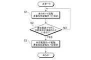
ここで、車両100における制御部50による制御動作の一例について更に説明する。図2は、本実施形態において、制御部50により燃料電池システム200に備わる燃料電池の出力を調節制御する手順の一例を示すフロー図である。 Here, an example of the control operation by the
本実施形態では、まず、制御部50が、通常時の運転モードとして、車両100の走行を司る走行モードを起動する(ステップS1)。この走行モードにおいては、燃料電池の高電位回避電圧として、第1の電圧V1が設定される。この第1の電圧V1としては、先に言及したとおり、例えば、Pt等の触媒金属の溶出やシンタリングによる触媒金属の反応面積の減少といったカソード極触媒層の劣化が比較的生じ難い電圧が設定され得る(より具体的な数値例については後述する。)。これにより、車両100の走行時において、燃料電池に含まれるPt等の触媒金属の過度の消費等が抑制される。 In the present embodiment, first, the
それから、制御部50は、単相電源プラグ70に、例えば家庭用家電製品、非常用照明、非常用電源回路機器等の図示しない外部負荷が接続されているか否かを判断する(ステップS2)。単相電源プラグ70に外部負荷が接続されていない(No)場合、制御部50は、ステップS1に戻って、そのまま走行モードで燃料電池の運転制御を行う。 Then, the
一方、単相電源プラグ70に外部負荷が接続されている(Yes)場合、制御部50は、例えば非常時の運転モードとして、外部負荷へ電力を供給するための外部電源モードを起動する(ステップS3)。この外部電源モードにおいては、燃料電池の高電位回避電圧として、第2の電圧V2が設定される。この外部電源モードにおける第2の電圧V2は、走行モードにおける第1の電圧V1よりも大きな値(V2>V1)とされる。より具体的には、第2の電圧V2が、燃料電池に含まれるPt等の触媒金属の酸化還元電位の領域よりも大きい電圧に設定されると好ましい。 On the other hand, when an external load is connected to the single-phase power plug 70 (Yes), the
ここで、表1に、モード種別(走行モード及び外部電源モード)の違いにおける必要スタック出力(上述の如くセルスタックとして構成されている燃料電池の総出力)及び高電位回避電圧V1,V2の一例、並びに、各モードの特徴をまとめて示す。 Here, Table 1 shows an example of necessary stack output (total output of the fuel cell configured as a cell stack as described above) and high potential avoidance voltages V1 and V2 in different mode types (running mode and external power supply mode). The characteristics of each mode are shown together.

走行モードにおける必要スタック出力は、例えば8.0〜110kW程度であり、必要スタック出力が例えば8.0kWのとき、高電位回避電圧である第1の電圧V1は、例えば0.85V程度に設定される(表1の例1))。一方、外部電源モードにおける必要スタック出力は、例えば8.0〜110kW程度であり、必要スタック出力が例えば5.0、0.5、及び0.0kWのとき、高電位回避電圧である第2の電圧V2は、それぞれ、例えば0.90、0.95V、及びOCV(1.0V)程度に設定される。なお、ここでの第1の電圧V1及び第2の電圧V2は、ともに燃料電池の単位セル電圧を示す。また、第2の電圧V2がOCV(1.0V)の場合には、実質的に高電位回避を行わないモードと捉えることもできる。 The necessary stack output in the running mode is, for example, about 8.0 to 110 kW. When the necessary stack output is, for example, 8.0 kW, the first voltage V1 that is a high potential avoidance voltage is set to, for example, about 0.85V. (Example 1 in Table 1)). On the other hand, the necessary stack output in the external power supply mode is, for example, about 8.0 to 110 kW. When the necessary stack output is, for example, 5.0, 0.5, and 0.0 kW, the second potential avoidance voltage is The voltage V2 is set to about 0.90, 0.95 V, and OCV (1.0 V), for example. Here, the first voltage V1 and the second voltage V2 are both unit cell voltages of the fuel cell. Further, when the second voltage V2 is OCV (1.0 V), it can be regarded as a mode in which high potential avoidance is not substantially performed.
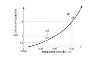
図3は、このような車両100に搭載された燃料電池の単位セル電圧とスタック出力との関係の一例を示すグラフであり、図示の曲線において、白抜き矢印R1で示す領域が走行モードに相当し、白抜き矢印R2で示す領域が外部電源モードに相当する。 FIG. 3 is a graph showing an example of the relationship between the unit cell voltage of the fuel cell mounted on the
このようにして走行モードの高電位回避電圧(第1の電圧V1)と外部電源モードの高電位回避電圧(第2の電圧V2)を選択的に設定するための手段、手法、又は手順としては、特に制限されず、例えば、制御部50による単位セル電圧の電位制御として、それらの高電位回避電圧の数値パラメータ等を切り替える制御が挙げられる。この場合、例えば、制御部50に内蔵されているメモリに、第1の電圧V1と第2の電圧V2の値(それぞれ単数でも複数でもよい)を予め格納しておき、図2に示すステップS1で走行モードを起動した際に、メモリから第1の電圧V1の値を読み出し、ステップS3で外部電源モードを起動した際には、メモリから第2の電圧V2の値を読み出し、それらの高電位回避電圧で燃料電池の運転制御を行う。 As a means, a method, or a procedure for selectively setting the high potential avoidance voltage (first voltage V1) in the traveling mode and the high potential avoidance voltage (second voltage V2) in the external power supply mode in this manner. For example, the control of the unit cell voltage by the
また、制御部50による単位セル電圧の別の電位制御として、上述の如く第1の電圧V1と第2の電圧V2として一定の値を用いる代わりに、例えば図3に示す曲線の関係式を制御部50のメモリに記憶しておき、単相電源プラグ70に接続される外部負荷の大きさや台数等に応じて必要とされる燃料電池のスタック出力と、その予め記憶しておいた関係式に基づいて、外部電源モードにおける高電位回避電圧を適宜設定するようにしてもよい。 Further, as another potential control of the unit cell voltage by the
或いは、制御部50による電位制御に代えて、燃料電池の発電量を左右する(影響を与える)種々の発電パラメータを、走行モード及び外部電源モードのそれぞれで、互いに異なるように調節する制御を行うこともできる。このような発電パラメータとしては、例えば、スタックへの燃料ガス及び/又は酸化ガスの供給量(流量)、スタックにおける加湿状態、スタックの温度等が挙げられる。 Alternatively, in place of the potential control by the
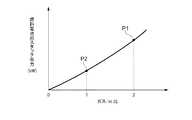
ここで、図4は、燃料電池のセルスタックに供給される酸化ガス(空気)と水蒸気量との比(以下「ガス/St.比」という)の値に対するスタック出力の変化の一例を模式的に示すグラフである。図4に示すとおり、ガス/St.比の値が大きくなるにつれて、スタック出力が増大する傾向にあり、同図においては、例えばガス/St.比=2のときに走行モードで燃料電池に必要とされるスタック出力P1を得ることができ、例えばガス/St.比=1のときに外部電源モードで燃料電池に必要とされるスタック出力P2を得ることができる。 Here, FIG. 4 schematically shows an example of a change in the stack output with respect to the value of the oxidizing gas (air) and the amount of water vapor (hereinafter referred to as “gas / St. Ratio”) supplied to the cell stack of the fuel cell. It is a graph shown in. As shown in FIG. As the value of the ratio increases, the stack output tends to increase. In the figure, for example, gas / St. When the ratio = 2, the stack output P1 required for the fuel cell in the traveling mode can be obtained. For example, the gas / St. When the ratio = 1, the stack output P2 required for the fuel cell in the external power supply mode can be obtained.
このことから、制御部50による電位制御上の発電パラメータとしての高電位回避電圧の値自体は、走行モードと外部電源モードで同一としつつ、制御部50によって例えば酸化ガスの供給量を変化させてガス/St.比を調節し、これにより、走行モード及び外部電源モードにおける高電位回避電圧が、それぞれ上述した第1の電圧V1及び第2の電圧Vと実質的に等価になるような制御を実現することができる。 From this, the value of the high potential avoidance voltage as a power generation parameter for potential control by the
また、単相電源プラグ70から外部負荷へ電力を供給する経路としては、燃料電池システム200のみからの送電、燃料電池システム200及び二次電池26の双方からの送電、並びに、二次電池26のみからの送電が挙げられる。これらのうち、二次電池26を用いて又は二次電池26を介して外部負荷へ送電する場合、燃料電池においては実質的な高電位回避を行わなくてもよい(例えば、第2の電圧V2を先述したようにOCV(1.0V)に設定する。)。 Further, as a path for supplying power from the single-
このように構成された車両100に備わる電源システム20によれば、外部電源モードにおいて、燃料電池の高電位回避電圧が、走行モードにおける第1の電圧V1よりも高い第2の電圧V2に設定されるので、外部負荷に電力を供給する外部電源モードを実行したときに、車両100の通常の走行モードにおける発電出力よりも小さい電力を出力することが可能となる。これにより、車両100に搭載された燃料電池システム200の燃料電池を外部電源として用いて、数kW程度以下の外部負荷に電力を供給するときに、従来の如く大量の余剰電力が発生してしまうことを十分に抑止することが可能となる。 According to the
したがって、車両100は、例えば災害時等に商用電力系統(商用電源)からの電力供給が喪失した場合に、一般家庭、避難施設、復旧現場等において電化製品等に電力を直接供給する外部電源としての極めて有用である。 Therefore, the
また、外部電源モードにおいて、燃料電池の出力を小さくする(低電力にする)ことができるので、燃料電池自体への負荷が低減され且つ発電電流が少なくなる。これにより、いわゆるIR損失等による出力損失を低減させることができ、その結果、燃料電池による発電効率を向上させることもできる。 Further, in the external power supply mode, the output of the fuel cell can be reduced (low power), so the load on the fuel cell itself is reduced and the generated current is reduced. Thereby, output loss due to so-called IR loss or the like can be reduced, and as a result, power generation efficiency by the fuel cell can be improved.
ここで、図5は、走行モード及び外部電源モードにおける燃料電池の単位セル電圧の経時変化を模式的に示すグラフである。図5において、実線のラインH1が走行モードにおける単位セル電圧を示し、一点鎖線で示すラインH2が外部電源モードにおける単位セル電圧を示す。また、同図において、斜線で示す電圧範囲Kは、触媒金属として用いられるPtの酸化還元電位の領域(ここでは大まかに0.70〜0.75V)を示す。この例では、走行モードにおける高電位回避電圧(第1の電圧V1)は、単位セル電圧=0.85V(スタック出力8.0kWに相当)に設定され、外部電源モードにおける高電位回避電圧(第2の電圧V2)は、単位セル電圧=0.95V(スタック出力0.5kWに相当)に設定される。 Here, FIG. 5 is a graph schematically showing a change with time of the unit cell voltage of the fuel cell in the running mode and the external power supply mode. In FIG. 5, a solid line H1 indicates a unit cell voltage in the traveling mode, and a line H2 indicated by a one-dot chain line indicates a unit cell voltage in the external power supply mode. In the same figure, a voltage range K indicated by hatching indicates a region of oxidation-reduction potential of Pt used as a catalyst metal (here, roughly 0.70 to 0.75 V). In this example, the high potential avoidance voltage (first voltage V1) in the running mode is set to unit cell voltage = 0.85 V (corresponding to a stack output of 8.0 kW), and the high potential avoidance voltage (first voltage in the external power supply mode) 2 voltage V2) is set to unit cell voltage = 0.95 V (corresponding to a stack output of 0.5 kW).
走行モードは、車両100の通常時の運転モードであって、運転時間は比較的長い。また、走行モードにおいては、ユーザ(車両100の運転者)によるアクセル37の開閉が道路状況や交通状況に応じて頻繁に行われる。そのため、図5のラインH1で示すように、燃料電池の単位セル電圧は、Ptの酸化還元電位(電圧範囲K)を跨いで変動する回数が比較的多くなる傾向にある。図示において、単位セル電圧が電圧範囲Kを超えると、触媒金属のPtは、酸化されてイオン化し溶出する一方、単位セル電圧が電圧範囲Kを下回ると、Ptイオンが還元されて原子化し、Ptが析出する。このようにして触媒金属の酸化還元が頻繁に生じる結果、表1にも記載したとおり、走行モードは、燃料電池の耐久性への影響が大きい。 The travel mode is a normal operation mode of the
これに対し、外部電源モードは、車両100の非常時の運転モードであって、運転時間は比較的短い。また、外部電源モードにおいては、ユーザによるアクセル37の開閉は通常行われない。よって、図5のラインH2で示すように、燃料電池の単位セル電圧は、Ptの酸化還元電位(電圧範囲K)を跨いで変動する回数は比較的非常に少ない傾向にある。その結果、外部電源モードでは、触媒金属の酸化還元が頻繁に生じることはないので、表1にも記載したとおり、外部電源モードによる燃料電池の耐久性への影響は小さい。したがって、外部電源モードの高電位回避電圧である第2の電圧V2を、走行モードにおける第1の電圧V1よりも高くしたとしても、燃料電池の性能劣化が促進されてしまうといった不都合を防止することができる。 In contrast, the external power supply mode is an emergency operation mode of the
換言すれば、外部電源モードの高電位回避電圧を高電位にすると低電位の場合に比して、触媒金属の溶出等が増加する傾向にあるものの、外部電源モードにおいては、上述の如く、触媒金属の酸化還元が頻繁に生じないことから、全体としてみたときに、燃料電池の性能劣化に対する影響は、実運転上、許容できるものとなる。一方、走行モードにおいては、触媒金属の酸化還元が外部電源モードに比して頻繁に生じ得るため、燃料電池の性能劣化をより抑制するべく、外部電源モードよりも低い高電位回避電圧を設定する必要がある。 In other words, if the high potential avoidance voltage in the external power supply mode is set to a high potential, elution of the catalyst metal or the like tends to increase as compared with the case of the low potential. Since metal oxidation / reduction does not occur frequently, the influence on the performance deterioration of the fuel cell is acceptable in actual operation when viewed as a whole. On the other hand, in the travel mode, oxidation / reduction of the catalytic metal can occur more frequently than in the external power supply mode. Therefore, a higher potential avoidance voltage lower than that in the external power supply mode is set in order to further suppress deterioration in fuel cell performance. There is a need.
なお、上述したとおり、本発明は上記実施形態に限定されるものではなく、その要旨を変更しない限度において様々な変形が可能である。 In addition, as above-mentioned, this invention is not limited to the said embodiment, A various deformation | transformation is possible in the limit which does not change the summary.
本発明による電源システムは、上述した優れた作用効果を奏することにより、燃料電池全般、燃料電池を備える車両、機器、システム、設備等、及び、それらの製造に広く且つ有効に利用することができ、単にそればかりではなく、災害時等に商用電源からの電力供給が喪失してしまったときに、一般家庭、避難施設、復旧現場等に電力を直接供給する外部電源としての利用性に極めて優れるものである。 The power supply system according to the present invention can be widely and effectively used for fuel cells in general, vehicles equipped with fuel cells, devices, systems, facilities, and the like, and their production by exhibiting the above-described excellent operational effects. Not only that, but when the power supply from the commercial power source is lost in the event of a disaster, etc., it is extremely useful as an external power source that directly supplies power to ordinary homes, evacuation facilities, restoration sites, etc. Is.
20 電源システム
26 二次電池(バッテリ)
28 残存容量モニタ
30 内部負荷部
31 トラクションモータ
32 ギヤ機構
34 車輪
35 アクセルセンサ
36 駆動回路
37 アクセル
40 ライン
50 制御部
64 DC−DCコンバータ
67 電流計
69 電圧計
70 単相電源プラグ
100 車両
200 燃料電池システム20
28 Remaining capacity monitor 30
Claims (2)
Translated fromJapanese前記燃料電池を、前記車両が走行する際の走行モードと、外部負荷に電力を供給するための外部電源モードとで切り替えて運転する制御を実行する制御部と、
を備えており、
前記制御部は、前記走行モードにおいては、前記燃料電池の発電時の高電位回避電圧を第1の電圧に設定し、前記外部電源モードにおいては、前記燃料電池の発電時の高電位回避電圧を、前記第1の電圧よりも高い第2の電圧に設定する、
電源システム。A fuel cell mounted on the vehicle;
A control unit that executes control to switch the fuel cell between a travel mode when the vehicle travels and an external power supply mode for supplying electric power to an external load;
With
The controller sets the high potential avoidance voltage during power generation of the fuel cell to a first voltage in the travel mode, and sets the high potential avoidance voltage during power generation of the fuel cell in the external power supply mode. Setting a second voltage higher than the first voltage;
Power system.
前記第2の電圧は、前記触媒金属の酸化還元電位の領域よりも大きい電圧に設定される、
請求項1記載の電源システム。The fuel cell includes a catalytic metal,
The second voltage is set to a voltage that is greater than the oxidation-reduction potential region of the catalytic metal.
The power supply system according to claim 1.
Priority Applications (5)
| Application Number | Priority Date | Filing Date | Title |
|---|---|---|---|
| JP2012048181AJP5737521B2 (en) | 2012-03-05 | 2012-03-05 | Power system |
| DE112013001280.4TDE112013001280T5 (en) | 2012-03-05 | 2013-03-04 | Power supply system |
| CN201380012733.0ACN104159780B (en) | 2012-03-05 | 2013-03-04 | Electric power system |
| PCT/IB2013/000474WO2013132315A2 (en) | 2012-03-05 | 2013-03-04 | Power supply system |
| US14/382,830US10029579B2 (en) | 2012-03-05 | 2013-03-04 | Power supply system |
Applications Claiming Priority (1)
| Application Number | Priority Date | Filing Date | Title |
|---|---|---|---|
| JP2012048181AJP5737521B2 (en) | 2012-03-05 | 2012-03-05 | Power system |
Publications (2)
| Publication Number | Publication Date |
|---|---|
| JP2013183619Atrue JP2013183619A (en) | 2013-09-12 |
| JP5737521B2 JP5737521B2 (en) | 2015-06-17 |
Family
ID=48093022
Family Applications (1)
| Application Number | Title | Priority Date | Filing Date |
|---|---|---|---|
| JP2012048181AActiveJP5737521B2 (en) | 2012-03-05 | 2012-03-05 | Power system |
Country Status (5)
| Country | Link |
|---|---|
| US (1) | US10029579B2 (en) |
| JP (1) | JP5737521B2 (en) |
| CN (1) | CN104159780B (en) |
| DE (1) | DE112013001280T5 (en) |
| WO (1) | WO2013132315A2 (en) |
Cited By (3)
| Publication number | Priority date | Publication date | Assignee | Title |
|---|---|---|---|---|
| JP2015115982A (en)* | 2013-12-09 | 2015-06-22 | 株式会社デンソー | Electric power output apparatus |
| CN106627152A (en)* | 2017-01-13 | 2017-05-10 | 北京新能源汽车股份有限公司 | External power supply control method and device |
| JP2020102344A (en)* | 2018-12-21 | 2020-07-02 | 株式会社豊田自動織機 | Moving body |
Families Citing this family (3)
| Publication number | Priority date | Publication date | Assignee | Title |
|---|---|---|---|---|
| US20170136968A1 (en)* | 2014-08-05 | 2017-05-18 | Panasonic Intellectual Property Management Co., Ltd. | In-vehicle electricity storage system |
| KR102551676B1 (en)* | 2018-08-17 | 2023-07-07 | 현대자동차주식회사 | External power supply system and supply method of fuel cell vehicle |
| EP4116129A1 (en)* | 2021-07-07 | 2023-01-11 | Volvo Truck Corporation | A method and a master control unit for controlling an electrical system of an electric vehicle |
Citations (3)
| Publication number | Priority date | Publication date | Assignee | Title |
|---|---|---|---|---|
| JP2003023706A (en)* | 2001-07-05 | 2003-01-24 | Toshiba Eng Co Ltd | Electric vehicle |
| JP2008218398A (en)* | 2007-02-05 | 2008-09-18 | Toyota Motor Corp | Fuel cell system |
| JP2008226591A (en)* | 2007-03-12 | 2008-09-25 | Toyota Motor Corp | Fuel cell system |
Family Cites Families (17)
| Publication number | Priority date | Publication date | Assignee | Title |
|---|---|---|---|---|
| US5858568A (en)* | 1996-09-19 | 1999-01-12 | Ztek Corporation | Fuel cell power supply system |
| JP4830197B2 (en)* | 2000-09-13 | 2011-12-07 | トヨタ自動車株式会社 | Fuel reformer |
| US20050052080A1 (en)* | 2002-07-31 | 2005-03-10 | Maslov Boris A. | Adaptive electric car |
| JP2004187385A (en) | 2002-12-02 | 2004-07-02 | Sumitomo Electric Ind Ltd | Distributed power system |
| KR100664090B1 (en)* | 2005-12-13 | 2007-01-03 | 엘지전자 주식회사 | Power supply control device and method for grid-connected fuel cell system |
| US7557464B2 (en)* | 2006-05-23 | 2009-07-07 | Continental Automotive Systems Us, Inc. | System and method for isolating sources and loads of a power system |
| JP5120594B2 (en)* | 2006-10-20 | 2013-01-16 | トヨタ自動車株式会社 | Fuel cell system and operation method thereof |
| JP2009076259A (en) | 2007-09-19 | 2009-04-09 | Sony Corp | Fuel cell system and voltage limiting method |
| US7800331B2 (en)* | 2007-11-27 | 2010-09-21 | Gm Global Technology Operations, Inc. | Method and system for operating an electric motor coupled to multiple power supplies |
| JP4461398B2 (en) | 2007-12-19 | 2010-05-12 | トヨタ自動車株式会社 | Fuel cell system |
| WO2010039109A1 (en)* | 2008-10-03 | 2010-04-08 | Utc Power Corporation | Low power control of fuel cell open circuit voltage |
| JP2012505628A (en)* | 2008-10-07 | 2012-03-01 | ボストン−パワー,インコーポレイテッド | Li-ion battery array for vehicles and other high capacity applications |
| KR100992654B1 (en)* | 2008-11-25 | 2010-11-05 | 기아자동차주식회사 | Air blow on / off control method of fuel cell vehicle |
| JP4781425B2 (en)* | 2008-12-25 | 2011-09-28 | 本田技研工業株式会社 | Power supply system between vehicle and house |
| US8508069B2 (en)* | 2010-06-01 | 2013-08-13 | GM Global Technology Operations LLC | Vehicular electrical systems |
| KR101230892B1 (en)* | 2010-11-05 | 2013-02-07 | 현대자동차주식회사 | Metallic porous media for fuel cell |
| US20130047616A1 (en)* | 2011-08-23 | 2013-02-28 | GM Global Technology Operations LLC | Electrical power cogeneration system |
- 2012
- 2012-03-05JPJP2012048181Apatent/JP5737521B2/enactiveActive
- 2013
- 2013-03-04CNCN201380012733.0Apatent/CN104159780B/enactiveActive
- 2013-03-04WOPCT/IB2013/000474patent/WO2013132315A2/enactiveApplication Filing
- 2013-03-04DEDE112013001280.4Tpatent/DE112013001280T5/enactivePending
- 2013-03-04USUS14/382,830patent/US10029579B2/enactiveActive
Patent Citations (3)
| Publication number | Priority date | Publication date | Assignee | Title |
|---|---|---|---|---|
| JP2003023706A (en)* | 2001-07-05 | 2003-01-24 | Toshiba Eng Co Ltd | Electric vehicle |
| JP2008218398A (en)* | 2007-02-05 | 2008-09-18 | Toyota Motor Corp | Fuel cell system |
| JP2008226591A (en)* | 2007-03-12 | 2008-09-25 | Toyota Motor Corp | Fuel cell system |
Cited By (4)
| Publication number | Priority date | Publication date | Assignee | Title |
|---|---|---|---|---|
| JP2015115982A (en)* | 2013-12-09 | 2015-06-22 | 株式会社デンソー | Electric power output apparatus |
| CN106627152A (en)* | 2017-01-13 | 2017-05-10 | 北京新能源汽车股份有限公司 | External power supply control method and device |
| JP2020102344A (en)* | 2018-12-21 | 2020-07-02 | 株式会社豊田自動織機 | Moving body |
| JP7268998B2 (en) | 2018-12-21 | 2023-05-08 | 株式会社豊田自動織機 | moving body |
Also Published As
| Publication number | Publication date |
|---|---|
| DE112013001280T5 (en) | 2014-12-18 |
| WO2013132315A8 (en) | 2013-11-07 |
| WO2013132315A3 (en) | 2014-03-13 |
| US10029579B2 (en) | 2018-07-24 |
| JP5737521B2 (en) | 2015-06-17 |
| CN104159780B (en) | 2016-08-24 |
| CN104159780A (en) | 2014-11-19 |
| US20150042154A1 (en) | 2015-02-12 |
| WO2013132315A2 (en) | 2013-09-12 |
Similar Documents
| Publication | Publication Date | Title |
|---|---|---|
| JP4888519B2 (en) | Fuel cell system and control method thereof | |
| CN101904036B (en) | fuel cell system | |
| CN101868881B (en) | Fuel cell system | |
| US8722265B2 (en) | Fuel cell system | |
| JP5737521B2 (en) | Power system | |
| CN104137315A (en) | Fuel cell system | |
| CN105609836A (en) | Fuel cell system and operation control method of the same | |
| WO2010052822A1 (en) | Fuel battery system | |
| JP2008527648A (en) | Reduction of voltage loss caused by voltage cycling by using rechargeable battery | |
| JP7115679B2 (en) | Fuel cell system and electric vehicle | |
| JP5725423B2 (en) | Fuel cell system | |
| JP4686842B2 (en) | Control method of fuel cell device | |
| JP2005346979A (en) | Fuel cell regeneration control device | |
| JP2015091207A (en) | Power supply system | |
| WO2013150619A1 (en) | Fuel cell system | |
| US9490494B2 (en) | Fuel cell system | |
| JP2007323997A (en) | Fuel cell system and operation method thereof | |
| JP2010244980A (en) | Fuel cell system and electric vehicle equipped with fuel cell system | |
| JPWO2013128610A1 (en) | Fuel cell system | |
| JP2020025426A (en) | Electric vehicle | |
| JP2010129343A (en) | Fuel cell system |
Legal Events
| Date | Code | Title | Description |
|---|---|---|---|
| A621 | Written request for application examination | Free format text:JAPANESE INTERMEDIATE CODE: A621 Effective date:20140528 | |
| TRDD | Decision of grant or rejection written | ||
| A01 | Written decision to grant a patent or to grant a registration (utility model) | Free format text:JAPANESE INTERMEDIATE CODE: A01 Effective date:20150325 | |
| A977 | Report on retrieval | Free format text:JAPANESE INTERMEDIATE CODE: A971007 Effective date:20150325 | |
| A61 | First payment of annual fees (during grant procedure) | Free format text:JAPANESE INTERMEDIATE CODE: A61 Effective date:20150407 | |
| R151 | Written notification of patent or utility model registration | Ref document number:5737521 Country of ref document:JP Free format text:JAPANESE INTERMEDIATE CODE: R151 |