JP2013182054A - Zoom lens and image capturing device - Google Patents
Zoom lens and image capturing deviceDownload PDFInfo
- Publication number
- JP2013182054A JP2013182054AJP2012044277AJP2012044277AJP2013182054AJP 2013182054 AJP2013182054 AJP 2013182054AJP 2012044277 AJP2012044277 AJP 2012044277AJP 2012044277 AJP2012044277 AJP 2012044277AJP 2013182054 AJP2013182054 AJP 2013182054A
- Authority
- JP
- Japan
- Prior art keywords
- lens group
- lens
- group
- zoom
- refractive power
- Prior art date
- Legal status (The legal status is an assumption and is not a legal conclusion. Google has not performed a legal analysis and makes no representation as to the accuracy of the status listed.)
- Pending
Links
- 230000014509gene expressionEffects0.000claimsabstractdescription44
- 230000003287optical effectEffects0.000claimsdescription45
- 238000003384imaging methodMethods0.000claimsdescription36
- 239000006185dispersionSubstances0.000claimsdescription15
- 230000002547anomalous effectEffects0.000claimsdescription10
- 239000002131composite materialSubstances0.000abstract1
- 230000004075alterationEffects0.000description47
- 230000005499meniscusEffects0.000description34
- 238000010586diagramMethods0.000description24
- 201000009310astigmatismDiseases0.000description12
- 230000000087stabilizing effectEffects0.000description7
- 239000006059cover glassSubstances0.000description6
- 238000006243chemical reactionMethods0.000description5
- 238000000034methodMethods0.000description5
- 230000007246mechanismEffects0.000description4
- 230000035945sensitivityEffects0.000description4
- 230000008859changeEffects0.000description3
- 230000006835compressionEffects0.000description2
- 238000007906compressionMethods0.000description2
- 230000007423decreaseEffects0.000description2
- 230000011514reflexEffects0.000description2
- 239000004065semiconductorSubstances0.000description2
- 238000005549size reductionMethods0.000description2
- 230000000295complement effectEffects0.000description1
- 230000006837decompressionEffects0.000description1
- 239000004973liquid crystal related substanceSubstances0.000description1
- 229910044991metal oxideInorganic materials0.000description1
- 150000004706metal oxidesChemical class0.000description1
Images


Landscapes
- Lenses (AREA)
- Adjustment Of Camera Lenses (AREA)
Abstract
Description
Translated fromJapanese本技術はズームレンズ及び撮像装置の技術分野に関する。詳しくは、レンズ交換式のデジタルカメラやデジタルスチルカメラ等の撮像装置及びこれに設けられるズームレンズに好適であり小型化を図る技術分野に関する。 The present technology relates to a technical field of a zoom lens and an imaging apparatus. More specifically, the present invention relates to a technical field that is suitable for an imaging apparatus such as an interchangeable lens digital camera or a digital still camera, and a zoom lens provided in the imaging apparatus, and to reduce the size.
近年、レンズ交換式のデジタル一眼レフカメラとコンパクトデジタルカメラの中間の機能性を有するレンズ交換式の小型のカメラが普及し始めている。 In recent years, interchangeable lens-type small cameras having functionality intermediate between interchangeable-lens digital single-lens reflex cameras and compact digital cameras have begun to spread.
一方、従来のネガティブリード型のズームレンズは広角ズームレンズに多く用いられており、従来の交換レンズ式の一眼レフカメラ用として広く普及している。 On the other hand, conventional negative lead type zoom lenses are widely used for wide-angle zoom lenses, and are widely used for conventional interchangeable lens type single-lens reflex cameras.
また、上記のようなカメラにおいては広角化の要求と共に特に小型化に対する要求が高くなっている。 Further, in the above-described cameras, there is a growing demand for downsizing as well as a wide angle.
しかしながら、広角ズームレンズにおいて小型化を実現しようとすると、第2レンズ群から像側の屈折力が大きくなり易く、大きな収差の発生やレンズ枚数の増加等の問題により小型化に支障を来たしていた。 However, if it is attempted to reduce the size of the wide-angle zoom lens, the refractive power on the image side from the second lens group tends to increase, resulting in problems such as large aberrations and an increase in the number of lenses. .
そこで、従来のズームレンズとして、ネガティブリード型の4群構成の広角ズームレンズが提案されており、良好な性能が実現されている(例えば、特許文献1参照)。 Thus, as a conventional zoom lens, a negative lead type four-group wide-angle zoom lens has been proposed, and good performance has been realized (for example, see Patent Document 1).
ところが、特許文献1に記載されたズームレンズにあっては、高性能化が図られているが、十分な小型化が図られていないと言う問題がある。 However, although the zoom lens described in
そこで、本技術ズームレンズ及び撮像装置は、上記した問題点を克服し、小型化を図ることを課題とする。 Thus, it is an object of the present technology zoom lens and imaging apparatus to overcome the above-described problems and to reduce the size.
第1に、ズームレンズは、上記した課題を解決するために、物体側から像側へ順に配置された負の屈折力を有する第1レンズ群と正の屈折力を有する第2レンズ群と負の屈折力を有する第3レンズ群と第4レンズ群を備え、広角端状態から望遠端状態への変倍に際し、前記第1レンズ群と前記第2レンズ群の間隔が縮小し、前記第2レンズ群と前記第3レンズ群の間隔が拡大し、前記第3レンズ群と前記第4レンズ群の間隔が縮小し、以下の条件式(1)を満足するものである。
(1)f2〜4/fw<3.0
但し、
f2〜4:第2レンズ群から第4レンズ群までの合成焦点距離
fw:広角端状態におけるレンズ全系の焦点距離
とする。First, in order to solve the above-described problem, the zoom lens includes a first lens group having a negative refractive power and a second lens group having a positive refractive power arranged in order from the object side to the image side. A third lens group and a fourth lens group having a refractive power of 2 are provided. When zooming from the wide-angle end state to the telephoto end state, the distance between the first lens group and the second lens group is reduced, and the second lens group is reduced. The distance between the lens group and the third lens group is enlarged, and the distance between the third lens group and the fourth lens group is reduced, and the following conditional expression (1) is satisfied.
(1) f2-4 / fw <3.0
However,
f2-4: The combined focal length fw from the second lens group to the fourth lens group fw: the focal length of the entire lens system in the wide-angle end state.
従って、ズームレンズにあっては、変倍時の光軸方向における可動レンズ群のストロークが短縮化される。 Therefore, in the zoom lens, the stroke of the movable lens group in the optical axis direction at the time of zooming is shortened.
第2に、上記したズームレンズにおいては、前記第2レンズ群は物体側から像側へ順に配置された第1部分群と第2部分群と第3部分群によって構成され、前記第2部分群が光軸方向に直交する方向へシフト可能な防振レンズ群とされ、以下の条件式(2)を満足することが望ましい。
(2)1.0<f2b/f2<6.0
但し、
f2b:第2部分群の焦点距離
f2:第2レンズ群の焦点距離
とする。Second, in the zoom lens described above, the second lens group includes a first partial group, a second partial group, and a third partial group that are arranged in order from the object side to the image side, and the second partial group. Is an anti-vibration lens group that can be shifted in a direction perpendicular to the optical axis direction, and it is desirable that the following conditional expression (2) is satisfied.
(2) 1.0 <f2b / f2 <6.0
However,
f2b: focal length of the second partial group f2: focal length of the second lens group.
ズームレンズにおいて、第2レンズ群は物体側から像側へ順に配置された第1部分群と第2部分群と第3部分群によって構成され、第2部分群が光軸方向に直交する方向へシフト可能な防振レンズ群とされ、条件式(2)を満足することにより、防振レンズ群の偏心敏感度が低くなると共に防振レンズ群の移動量が低減される。 In the zoom lens, the second lens group includes a first partial group, a second partial group, and a third partial group that are arranged in order from the object side to the image side, and the second partial group is in a direction orthogonal to the optical axis direction. By making the shiftable anti-vibration lens group and satisfying the conditional expression (2), the decentering sensitivity of the anti-vibration lens group is lowered and the movement amount of the anti-vibration lens group is reduced.
第3に、上記したズームレンズにおいては、前記第3レンズ群が合焦のために光軸方向へ移動可能なフォーカスレンズ群とされることが望ましい。 Third, in the zoom lens described above, it is desirable that the third lens group is a focus lens group that can move in the optical axis direction for focusing.
第3レンズ群が合焦のために光軸方向へ移動可能なフォーカスレンズ群とされることにより、小型かつ軽量なレンズ群がフォーカシング時に移動される。 By making the third lens group a focus lens group that can move in the optical axis direction for focusing, the small and lightweight lens group is moved during focusing.
第4に、上記したズームレンズにおいては、前記第3レンズ群が1枚のレンズによって構成されることが望ましい。 Fourth, in the zoom lens described above, it is desirable that the third lens group is constituted by a single lens.
第3レンズ群が1枚のレンズによって構成されることにより、第3レンズ群の小型化及び軽量化が図られる。 By configuring the third lens group with a single lens, the third lens group can be reduced in size and weight.
第5に、上記したズームレンズにおいては、前記第2レンズ群の最も物体側に配置されたレンズから前記第2レンズ群の最も像側に配置されたレンズまでの間に開口絞りが配置されることが望ましい。 Fifth, in the zoom lens described above, an aperture stop is disposed between the lens disposed closest to the object side of the second lens group and the lens disposed closest to the image side of the second lens group. It is desirable.
第2レンズ群の最も物体側に配置されたレンズから第2レンズ群の最も像側に配置されたレンズまでの間に開口絞りが配置されることにより、第2レンズ群の対称性を確保することが可能になる。 An aperture stop is disposed between the lens disposed closest to the object side of the second lens group and the lens disposed closest to the image side of the second lens group, thereby ensuring symmetry of the second lens group. It becomes possible.
第6に、上記したズームレンズにおいては、前記第4レンズ群にg線、d線における正常分散直線からのずれ量である異常分散性の値が正の凸レンズと負の凹レンズとが少なくとも1枚ずつ配置されることが望ましい。 Sixth, in the zoom lens described above, the fourth lens group includes at least one convex lens having a positive value of anomalous dispersion, which is an amount of deviation from the normal dispersion line in the g-line and d-line, and a negative concave lens. It is desirable to arrange them one by one.
第4レンズ群にg線、d線における正常分散直線からのずれ量である異常分散性の値が正の凸レンズと負の凹レンズとが少なくとも1枚ずつ配置されることにより、異常分散性を利用して倍率色収差を補正することが可能になる。 Anomalous dispersibility is utilized by arranging at least one convex lens and one negative concave lens having anomalous dispersion value which is a deviation amount from the normal dispersion line in the g-line and d-line in the fourth lens group. Thus, it becomes possible to correct the lateral chromatic aberration.
撮像装置は、上記した課題を解決するために、ズームレンズと前記ズームレンズによって形成された光学像を電気的信号に変換する撮像素子とを備え、前記ズームレンズは、物体側から像側へ順に配置された負の屈折力を有する第1レンズ群と正の屈折力を有する第2レンズ群と負の屈折力を有する第3レンズ群と第4レンズ群を備え、広角端状態から望遠端状態への変倍に際し、前記第1レンズ群と前記第2レンズ群の間隔が縮小し、前記第2レンズ群と前記第3レンズ群の間隔が拡大し、前記第3レンズ群と前記第4レンズ群の間隔が縮小し、以下の条件式(1)を満足する。
(1)f2〜4/fw<3.0
但し、
f2〜4:第2レンズ群から第4レンズ群までの合成焦点距離
fw:広角端状態におけるレンズ全系の焦点距離
とする。In order to solve the above-described problem, the imaging apparatus includes a zoom lens and an imaging element that converts an optical image formed by the zoom lens into an electrical signal, and the zoom lens sequentially moves from the object side to the image side. A first lens group having a negative refractive power, a second lens group having a positive refractive power, a third lens group having a negative refractive power, and a fourth lens group, arranged from a wide-angle end state to a telephoto end state; In zooming, the distance between the first lens group and the second lens group is reduced, the distance between the second lens group and the third lens group is enlarged, and the third lens group and the fourth lens are enlarged. The group interval is reduced, and the following conditional expression (1) is satisfied.
(1) f2-4 / fw <3.0
However,
f2-4: The combined focal length fw from the second lens group to the fourth lens group fw: the focal length of the entire lens system in the wide-angle end state.
従って、撮像装置にあっては、ズームレンズにおいて、変倍時の光軸方向における可動レンズ群のストロークが短縮化される。 Therefore, in the imaging apparatus, in the zoom lens, the stroke of the movable lens group in the optical axis direction during zooming is shortened.
本技術ズームレンズは、物体側から像側へ順に配置された負の屈折力を有する第1レンズ群と正の屈折力を有する第2レンズ群と負の屈折力を有する第3レンズ群と第4レンズ群を備え、広角端状態から望遠端状態への変倍に際し、前記第1レンズ群と前記第2レンズ群の間隔が縮小し、前記第2レンズ群と前記第3レンズ群の間隔が拡大し、前記第3レンズ群と前記第4レンズ群の間隔が縮小し、以下の条件式(1)を満足する。
(1)f2〜4/fw<3.0
但し、
f2〜4:第2レンズ群から第4レンズ群までの合成焦点距離
fw:広角端状態におけるレンズ全系の焦点距離
とする。The zoom lens according to the present technology includes a first lens group having a negative refractive power, a second lens group having a positive refractive power, a third lens group having a negative refractive power, and a third lens group, which are arranged in order from the object side to the image side. 4 lens groups, and during zooming from the wide-angle end state to the telephoto end state, the distance between the first lens group and the second lens group is reduced, and the distance between the second lens group and the third lens group is The distance between the third lens group and the fourth lens group is reduced and the following conditional expression (1) is satisfied.
(1) f2-4 / fw <3.0
However,
f2-4: The combined focal length fw from the second lens group to the fourth lens group fw: the focal length of the entire lens system in the wide-angle end state.
従って、変倍時の光軸方向における可動レンズ群のストロークが短縮化され、小型化を図ることができる。 Therefore, the stroke of the movable lens group in the optical axis direction at the time of zooming is shortened, and the size can be reduced.
請求項2に記載した技術にあっては、前記第2レンズ群は物体側から像側へ順に配置された第1部分群と第2部分群と第3部分群によって構成され、前記第2部分群が光軸方向に直交する方向へシフト可能な防振レンズ群とされ、以下の条件式(2)を満足する。
(2)1.0<f2b/f2<6.0
但し、
f2b:第2部分群の焦点距離
f2:第2レンズ群の焦点距離
とする。In the technique described in claim 2, the second lens group includes a first partial group, a second partial group, and a third partial group that are arranged in order from the object side to the image side, and the second part. The group is an anti-vibration lens group that can be shifted in a direction orthogonal to the optical axis direction, and satisfies the following conditional expression (2).
(2) 1.0 <f2b / f2 <6.0
However,
f2b: focal length of the second partial group f2: focal length of the second lens group.
従って、防振レンズ群の偏心敏感度が低くなると共に防振レンズ群の移動量が低減され、手振れ補正機構の制御の精度の向上及びレンズの径方向における小型化を図ることができる。 Accordingly, the sensitivity of decentering of the image stabilizing lens group is lowered and the amount of movement of the image stabilizing lens group is reduced, so that the control accuracy of the camera shake correction mechanism can be improved and the lens can be downsized in the radial direction.
請求項3に記載した技術にあっては、前記第3レンズ群が合焦のために光軸方向へ移動可能なフォーカスレンズ群とされている。 In the technique described in
従って、小型かつ軽量なレンズ群がフォーカシング時に移動されることになり、高速駆動に適した構成を実現することができる。 Therefore, a small and lightweight lens group is moved during focusing, and a configuration suitable for high-speed driving can be realized.
請求項4に記載した技術にあっては、前記第3レンズ群が1枚のレンズによって構成されている。 In the technique described in
従って、第3レンズ群の小型化及び軽量化が図られ、高速駆動に適した最良な構成を実現することができる。 Accordingly, the third lens group can be reduced in size and weight, and the best configuration suitable for high-speed driving can be realized.
請求項5に記載した技術にあっては、前記第2レンズ群の最も物体側に配置されたレンズから前記第2レンズ群の最も像側に配置されたレンズまでの間に開口絞りが配置されている。 In the technique described in claim 5, an aperture stop is disposed between a lens disposed closest to the object side of the second lens group and a lens disposed closest to the image side of the second lens group. ing.
従って、第2レンズ群の対称性を確保することが可能になり、良好な収差補正を行うことができ高性能化を図ることができる。 Therefore, it becomes possible to ensure the symmetry of the second lens group, to perform good aberration correction, and to achieve high performance.
請求項6に記載した技術にあっては、前記第4レンズ群にg線、d線における正常分散直線からのずれ量である異常分散性の値が正の凸レンズと負の凹レンズとが少なくとも1枚ずつ配置されている。 In the technique described in claim 6, the fourth lens group includes at least one convex lens and a negative concave lens having a positive value of anomalous dispersion that is a deviation amount from a normal dispersion line in the g-line and d-line. It is arranged one by one.
従って、異常分散性を利用して倍率色収差を効果的に補正することが可能になり、小型化した際の広角端において発生する倍率色収差が低減され、小型化と高性能化の両立を図ることができる。 Therefore, it is possible to effectively correct the lateral chromatic aberration by utilizing the anomalous dispersion, and the lateral chromatic aberration that occurs at the wide-angle end when downsizing is reduced, so that both downsizing and high performance can be achieved. Can do.
本技術撮像装置は、ズームレンズと前記ズームレンズによって形成された光学像を電気的信号に変換する撮像素子とを備え、前記ズームレンズは、物体側から像側へ順に配置された負の屈折力を有する第1レンズ群と正の屈折力を有する第2レンズ群と負の屈折力を有する第3レンズ群と第4レンズ群を備え、広角端状態から望遠端状態への変倍に際し、前記第1レンズ群と前記第2レンズ群の間隔が縮小し、前記第2レンズ群と前記第3レンズ群の間隔が拡大し、前記第3レンズ群と前記第4レンズ群の間隔が縮小し、以下の条件式(1)を満足する撮像装置。
(1)f2〜4/fw<3.0
但し、
f2〜4:第2レンズ群から第4レンズ群までの合成焦点距離
fw:広角端状態におけるレンズ全系の焦点距離
とする。An imaging apparatus according to an embodiment of the present technology includes a zoom lens and an imaging element that converts an optical image formed by the zoom lens into an electrical signal, and the zoom lens has negative refractive power arranged in order from the object side to the image side. A first lens group having positive refractive power, a second lens group having positive refractive power, a third lens group having negative refractive power, and a fourth lens group, and at the time of zooming from the wide-angle end state to the telephoto end state, An interval between the first lens group and the second lens group is reduced; an interval between the second lens group and the third lens group is enlarged; an interval between the third lens group and the fourth lens group is reduced; An imaging device that satisfies the following conditional expression (1).
(1) f2-4 / fw <3.0
However,
f2-4: The combined focal length fw from the second lens group to the fourth lens group fw: the focal length of the entire lens system in the wide-angle end state.
従って、ズームレンズにおける変倍時の光軸方向における可動レンズ群のストロークが短縮化され、小型化を図ることができる。 Therefore, the stroke of the movable lens group in the optical axis direction at the time of zooming in the zoom lens is shortened, and the size can be reduced.
以下に、本技術ズームレンズ及び撮像装置を実施するための最良の形態について説明する。 The best mode for carrying out the zoom lens and the imaging apparatus of the present technology will be described below.
[ズームレンズの構成]
本技術ズームレンズは、物体側から像側へ順に配置された負の屈折力を有する第1レンズ群と正の屈折力を有する第2レンズ群と負の屈折力を有する第3レンズ群と第4レンズ群を備え、広角端状態から望遠端状態への変倍に際し、前記第1レンズ群と前記第2レンズ群の間隔が縮小し、前記第2レンズ群と前記第3レンズ群の間隔が拡大し、前記第3レンズ群と前記第4レンズ群の間隔が縮小し、以下の条件式(1)を満足する。
(1)f2〜4/fw<3.0
但し、
f2〜4:第2レンズ群から第4レンズ群までの合成焦点距離
fw:広角端状態におけるレンズ全系の焦点距離
とする。[Configuration of zoom lens]
The zoom lens according to the present technology includes a first lens group having a negative refractive power, a second lens group having a positive refractive power, a third lens group having a negative refractive power, and a third lens group, which are arranged in order from the object side to the image side. 4 lens groups, and during zooming from the wide-angle end state to the telephoto end state, the distance between the first lens group and the second lens group is reduced, and the distance between the second lens group and the third lens group is The distance between the third lens group and the fourth lens group is reduced and the following conditional expression (1) is satisfied.
(1) f2-4 / fw <3.0
However,
f2-4: The combined focal length fw from the second lens group to the fourth lens group fw: the focal length of the entire lens system in the wide-angle end state.
条件式(1)は、広角端状態におけるレンズ全系の屈折力と第2レンズ群から第4レンズ群までの屈折力との関係を規定する式である。 Conditional expression (1) defines the relationship between the refractive power of the entire lens system in the wide-angle end state and the refractive power from the second lens group to the fourth lens group.
条件式(1)を満たさない場合には、変倍時の光軸方向における可動レンズ群のストロークが長くなりレンズ系の全長が長くなって小型化が阻害されてしまう。 When the conditional expression (1) is not satisfied, the stroke of the movable lens group in the optical axis direction at the time of zooming becomes long, and the total length of the lens system becomes long, so that downsizing is hindered.
従って、ズームレンズが条件式(1)を満足することにより、変倍時の光軸方向における可動レンズ群のストロークが短縮化され、小型化を図ることができる。 Therefore, when the zoom lens satisfies the conditional expression (1), the stroke of the movable lens group in the optical axis direction at the time of zooming can be shortened and the size can be reduced.
尚、本技術ズームレンズにおいては、以下の条件式(1)′を満足することがより好ましい。
(1)′f2〜4/fw<2.7
ズームレンズが条件式(1)′を満足することにより、変倍時の光軸方向における可動レンズ群のストロークが一層短縮化され、一層の小型化を図ることができる。In the zoom lens according to the present technology, it is more preferable that the following conditional expression (1) ′ is satisfied.
(1) 'f2-4 / fw <2.7
When the zoom lens satisfies the conditional expression (1) ′, the stroke of the movable lens group in the optical axis direction during zooming can be further shortened, and further miniaturization can be achieved.
また、本技術ズームレンズにおいては、以下の条件式(1)′′を満足することがより一層好ましい。
(1)′′f2〜4/fw<2.4
ズームレンズが条件式(1)′′を満足することにより、変倍時の光軸方向における可動レンズ群のストロークがより一層短縮化され、より一層の小型化を図ることができる。In the zoom lens according to the present technology, it is more preferable that the following conditional expression (1) ″ is satisfied.
(1) "f2-4 / fw <2.4
When the zoom lens satisfies the conditional expression (1) ″, the stroke of the movable lens group in the optical axis direction at the time of zooming can be further shortened, and further miniaturization can be achieved.
本技術の一実施形態によるズームレンズにあっては、前記第2レンズ群は物体側から像側へ順に配置された第1部分群と第2部分群と第3部分群によって構成され、前記第2部分群が光軸方向に直交する方向へシフト可能な防振レンズ群とされ、以下の条件式(2)を満足することが望ましい。
(2)1.0<f2b/f2<6.0
但し、
f2b:第2部分群の焦点距離
f2:第2レンズ群の焦点距離
とする。In the zoom lens according to the embodiment of the present technology, the second lens group includes a first partial group, a second partial group, and a third partial group that are arranged in order from the object side to the image side. It is desirable that the two sub-groups are anti-vibration lens groups that can be shifted in a direction perpendicular to the optical axis direction, and that the following conditional expression (2) is satisfied.
(2) 1.0 <f2b / f2 <6.0
However,
f2b: focal length of the second partial group f2: focal length of the second lens group.
条件式(2)は、防振レンズ群と手ぶれ補正の性能に関する式である。 Conditional expression (2) is an expression relating to the image stabilizing lens group and the camera shake correction performance.
条件式(2)の上限を上回ると、防振レンズ群の偏心敏感度が高くなり手振れ補正機構の制御の精度が低下してしまう。 If the upper limit of conditional expression (2) is exceeded, the sensitivity of decentering of the vibration-proof lens group will increase, and the accuracy of control of the camera shake correction mechanism will decrease.
逆に、条件式(2)の下限を下回ると、レンズ系全体の倍率に対する防振レンズ群の倍率が低下し、防振レンズ群の移動量が増加することによりレンズの径方向における大型化を来たしてしまう。 Conversely, if the lower limit of conditional expression (2) is not reached, the magnification of the image stabilizing lens group with respect to the magnification of the entire lens system decreases, and the amount of movement of the image stabilizing lens group increases, thereby increasing the size of the lens in the radial direction. I will come.
従って、ズームレンズが条件式(2)を満足することにより、防振レンズ群の偏心敏感度が低くなると共に防振レンズ群の移動量が低減され、手振れ補正機構の制御の精度の向上及びレンズの径方向における小型化を図ることができる。 Therefore, when the zoom lens satisfies the conditional expression (2), the sensitivity of decentering of the image stabilizing lens group is lowered and the amount of movement of the image stabilizing lens group is reduced, the control accuracy of the camera shake correction mechanism is improved, and the lens The size in the radial direction can be reduced.
尚、ズームレンズにおいては、以下の条件式(2)′を満足することがより好ましい。
(2)′2.0<f2b/f2<6.0
ズームレンズが条件式(2)′を満足することにより、手振れ補正機構の制御の精度の一層の向上及びレンズの径方向における一層の小型化を図ることができる。In the zoom lens, it is more preferable that the following conditional expression (2) ′ is satisfied.
(2) '2.0 <f2b / f2 <6.0
When the zoom lens satisfies the conditional expression (2) ′, it is possible to further improve the control accuracy of the camera shake correction mechanism and further reduce the size of the lens in the radial direction.
本技術の一実施形態によるズームレンズにあっては、前記第3レンズ群が合焦のために光軸方向へ移動可能なフォーカスレンズ群とされることが望ましい。 In the zoom lens according to an embodiment of the present technology, it is desirable that the third lens group is a focus lens group that can move in the optical axis direction for focusing.
近年、撮像装置において動画対応及び高速で移動する被写体に対する動体撮影性能の要求が高く、インナーフォーカスタイプのレンズでは、特に、高速でフォーカス動作が行われる必要があり、フォーカスレンズ群の小型化及び軽量化の要求が高い。 In recent years, there has been a high demand for moving object shooting performance with respect to moving images and high-speed moving objects in image pickup apparatuses. In particular, with an inner focus type lens, it is necessary to perform a focusing operation at a high speed, and the focus lens group is reduced in size and weight. The demand for conversion is high.
一方、ネガティブリードタイプの広角ズームレンズにおいては、第2レンズ群を通過した光線の幅が最も狭いため、第3レンズ群には径の小さなレンズが配置されている。 On the other hand, in a negative lead type wide-angle zoom lens, since the width of the light beam that has passed through the second lens group is the narrowest, a lens having a small diameter is disposed in the third lens group.
そこで、上記のように、第2レンズ群の像側に配置される第3レンズ群をフォーカスレンズ群とすることにより、小型かつ軽量なレンズ群がフォーカシング時に移動されることになり、高速駆動に適した構成を実現することができる。 Therefore, as described above, by using the third lens group arranged on the image side of the second lens group as the focus lens group, the small and lightweight lens group is moved during focusing, which enables high-speed driving. A suitable configuration can be realized.
本技術の一実施形態によるズームレンズにあっては、前記第3レンズ群が1枚のレンズによって構成されていることが望ましい。 In the zoom lens according to an embodiment of the present technology, it is preferable that the third lens group is constituted by a single lens.
第3レンズ群が1枚のレンズによって構成されていることにより、第3レンズ群の小型化及び軽量化が図られ、高速駆動に適した最良な構成を実現することができる。 Since the third lens group is composed of a single lens, the third lens group can be reduced in size and weight, and the best configuration suitable for high-speed driving can be realized.
本技術の一実施形態によるズームレンズにあっては、前記第2レンズ群の最も物体側に配置されたレンズから前記第2レンズ群の最も像側に配置されたレンズまでの間に開口絞りが配置されることが望ましい。 In a zoom lens according to an embodiment of the present technology, an aperture stop is provided between a lens disposed closest to the object side of the second lens group and a lens disposed closest to the image side of the second lens group. It is desirable to be arranged.
第2レンズ群の最も物体側に配置されたレンズから第2レンズ群の最も像側に配置されたレンズまでの間に開口絞りが配置されることにより、第2レンズ群の対称性を確保することが可能になり、良好な収差補正を行うことができ高性能化を図ることができる。 An aperture stop is disposed between the lens disposed closest to the object side of the second lens group and the lens disposed closest to the image side of the second lens group, thereby ensuring symmetry of the second lens group. Therefore, it is possible to correct aberrations satisfactorily and achieve high performance.
本技術の一実施形態によるズームレンズにあっては、前記第4レンズ群にg線、d線における正常分散直線からのずれ量である異常分散性の値が正の凸レンズと負の凹レンズとが少なくとも1枚ずつ配置されることが望ましい。 In the zoom lens according to an embodiment of the present technology, the fourth lens group includes a convex lens having a positive value of anomalous dispersion and a negative concave lens having a deviation amount from a normal dispersion line in the g-line and the d-line. It is desirable to arrange at least one by one.
広角ズームレンズの広角端においては、第1レンズ群に起因する倍率色収差が発生し易くなるため、最終レンズ群である第4レンズ群によって倍率色収差を効果的に補正する必要がある。一方、小型化を図るためには第4レンズ群のレンズの枚数を少なくすることが望ましいが、レンズの枚数を少なくすると倍率色収差を効果的に補正し難くなり、小型化と高性能化を両立させることができなくなるおそれがある。 At the wide-angle end of the wide-angle zoom lens, chromatic aberration of magnification due to the first lens group is likely to occur. Therefore, it is necessary to effectively correct the chromatic aberration of magnification by the fourth lens group as the final lens group. On the other hand, in order to reduce the size, it is desirable to reduce the number of lenses in the fourth lens group. However, if the number of lenses is reduced, it will be difficult to effectively correct the lateral chromatic aberration, and both miniaturization and high performance will be achieved. There is a risk that it will not be possible.
そこで、上記したように、第4レンズ群に異常分散性の値が正の凸レンズと負の凹レンズとを少なくとも1枚ずつ配置することにより、異常分散性を利用して倍率色収差を効果的に補正することが可能になり、小型化した際の広角端において発生する倍率色収差が低減され、小型化と高性能化の両立を図ることができる。 Therefore, as described above, by arranging at least one convex lens having a positive anomalous dispersion value and one negative concave lens in the fourth lens group, the lateral chromatic aberration can be effectively corrected using the anomalous dispersion. Therefore, the lateral chromatic aberration generated at the wide-angle end when the size is reduced is reduced, and both size reduction and high performance can be achieved.
[ズームレンズの数値実施例]
以下に、本技術ズームレンズの具体的な実施の形態及び実施の形態に具体的な数値を適用した数値実施例について、図面及び表を参照して説明する。[Numerical example of zoom lens]
Hereinafter, specific embodiments of the zoom lens according to the present technology and numerical examples in which specific numerical values are applied to the embodiments will be described with reference to the drawings and tables.
尚、以下の各表や説明において示した記号の意味等については、下記に示す通りである。 The meanings of symbols shown in the following tables and explanations are as shown below.
「面番号」は物体側から像側へ数えた第i番目の面の面番号、「Ri」は第i番目の面の近軸曲率半径、「Di」は第i番目の面と第i+1番目の面の間の軸上面間隔(レンズの中心の厚み又は空気間隔)、「Ni」は第i番目の面から始まるレンズ等のd線(λ=587.6nm)における屈折率、「νi」は第i番目の面から始まるレンズ等のd線におけるアッベ数を示す。 "Surface number" is the surface number of the i-th surface counted from the object side to the image side, "Ri" is the paraxial radius of curvature of the i-th surface, and "Di" is the i-th surface and i + 1-th surface The distance between the upper surfaces of the axes (the thickness of the center of the lens or the air distance), “Ni” is the refractive index at the d-line (λ = 587.6 nm) of the lens or the like starting from the i-th surface, and “νi” is The Abbe number in the d line of a lens or the like starting from the i-th surface is shown.
「面番号」に関し「ASP」は当該面が非球面であることを示し、「Ri」に関し「INFINITY」は当該面が平面であることを示し、「Di」に関し「可変」は可変間隔であることを示す。 “ASP” for “surface number” indicates that the surface is aspherical, “INFINITY” for “Ri” indicates that the surface is a plane, and “variable” for “Di” is a variable interval. It shows that.
「κ」は円錐定数(コーニック定数)、「A4」、「A6」、「A8」、「A10」はそれぞれ4次、6次、8次、10次の非球面係数を示す。 “Κ” represents a conic constant (conic constant), and “A4”, “A6”, “A8”, and “A10” represent fourth-order, sixth-order, eighth-order, and tenth-order aspherical coefficients, respectively.
「f」は焦点距離、「Fno.」はFナンバー、「ω」は半画角を示す。 “F” indicates a focal length, “Fno.” Indicates an F number, and “ω” indicates a half angle of view.
尚、以下の非球面係数を示す各表において、「E−n」は10を底とする指数表現、即ち、「10のマイナスn乗」を表しており、例えば、「0.12345E−05」は「0.12345×(10のマイナス五乗)」を表している。 In each table showing the following aspheric coefficients, “E−n” represents an exponential expression with a base of 10, that is, “10 to the negative n”, for example, “0.12345E-05”. Represents “0.12345 × (10 to the fifth power)”.
各実施の形態において用いられたズームレンズには、レンズ面が非球面に形成されたものがある。非球面形状は、「x」をレンズ面の頂点からの光軸方向における距離(サグ量)、「y」を光軸方向に垂直な方向における高さ(像高)、「c」をレンズの頂点における近軸曲率(曲率半径の逆数)、「κ」を円錐定数(コーニック定数)、「A4」、「A6」、「A8」、「A10」をそれぞれ4次、6次、8次、10次の非球面係数とすると、以下の数式1によって定義される。 Some zoom lenses used in the embodiments have an aspheric lens surface. In the aspherical shape, “x” is the distance (sag amount) in the optical axis direction from the apex of the lens surface, “y” is the height (image height) in the direction perpendicular to the optical axis direction, and “c” is the lens surface. Paraxial curvature at the apex (the reciprocal of the radius of curvature), “κ” is the conic constant (conic constant), “A4”, “A6”, “A8”, “A10” are 4th, 6th, 8th, 10 The following aspheric coefficient is defined by the following

<第1の実施の形態>
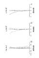
図1は、本技術の第1の実施の形態におけるズームレンズ1のレンズ構成を示している。<First Embodiment>
FIG. 1 shows a lens configuration of the
ズームレンズ1は変倍比が1.70倍にされている。 The
ズームレンズ1は、物体側から像側へ順に、負の屈折力を有する第1レンズ群GR1、正の屈折力を有する第2レンズ群GR2、負の屈折力を有する第3レンズ群GR3、負の屈折力を有する第4レンズ群GR4が配列されて成る。 The
ズームレンズ1は、広角端状態から望遠端状態への変倍に際し、第1レンズ群GR1と第2レンズ群GR2の間隔が縮小し、第2レンズ群GR2と第3レンズ群GR3の間隔が拡大し、第3レンズ群GR3と第4レンズ群GR4の間隔が縮小するように各レンズ群が光軸方向へ移動される。 When zooming from the wide-angle end state to the telephoto end state, the
第1レンズ群GR1は、物体側から像側へ順に、物体側に凸面を向けたメニスカスレンズL1と両凹レンズL2と両凸レンズL3の3枚のレンズによって構成されている。 The first lens group GR1 is composed of three lenses, a meniscus lens L1, a biconcave lens L2, and a biconvex lens L3 having a convex surface facing the object side in order from the object side to the image side.
第2レンズ群GR2は、物体側から像側へ順に、物体側に凸面を向けたメニスカスレンズL4と物体側に凸面を向けたメニスカスレンズL5との接合レンズと、両凸レンズL6と、両凸レンズL7と、像側に凸面を向けたメニスカスレンズL8との5枚のレンズによって構成されている。 The second lens group GR2 includes, in order from the object side to the image side, a cemented lens of a meniscus lens L4 having a convex surface facing the object side and a meniscus lens L5 having a convex surface facing the object side, a biconvex lens L6, and a biconvex lens L7. And a meniscus lens L8 having a convex surface facing the image side.
第2レンズ群GR2は、物体側から像側へ順に配列された第1部分群G2aと第2部分群G2bと第3部分群G2cとから成る。第1部分群G2aはメニスカスレンズL4とメニスカスレンズL5によって構成され、第2部分群G2bは両凸レンズL6によって構成され、第3部分群G2cは両凸レンズL7とメニスカスレンズL8によって構成されている。 The second lens group GR2 includes a first partial group G2a, a second partial group G2b, and a third partial group G2c arranged in order from the object side to the image side. The first partial group G2a is constituted by a meniscus lens L4 and a meniscus lens L5, the second partial group G2b is constituted by a biconvex lens L6, and the third partial group G2c is constituted by a biconvex lens L7 and a meniscus lens L8.
第2部分群G2bは光軸方向に直交する方向へシフト可能な防振レンズ群とされている。 The second partial group G2b is an anti-vibration lens group that can be shifted in a direction orthogonal to the optical axis direction.
第3レンズ群GR3は、メニスカスレンズL9の1枚のレンズによって構成されている。第3レンズ群GR3は合焦のために光軸方向へ移動可能なフォーカスレンズ群とされている。 The third lens group GR3 is configured by one lens of the meniscus lens L9. The third lens group GR3 is a focus lens group that can move in the optical axis direction for focusing.
第4レンズ群GR4は、像側に凸面を向けたメニスカスレンズL10と、像側に凸面を向けたメニスカスレンズL11と物体側に凹面を向けたメニスカスレンズL12との接合レンズとの3枚のレンズによって構成されている。 The fourth lens group GR4 includes three lenses including a meniscus lens L10 having a convex surface facing the image side, a cemented lens of a meniscus lens L11 having a convex surface facing the image side and a meniscus lens L12 having a concave surface facing the object side. It is constituted by.
第2レンズ群GR2における第1部分群G2aと第2部分群G2bの間には開口絞りSが配置され、開口絞りSは第2部分群G2と一体になって光軸方向へ移動される。尚、開口絞りSは第2部分群G2bと第3部分群G2cの間に配置されていてもよい。 An aperture stop S is disposed between the first partial group G2a and the second partial group G2b in the second lens group GR2, and the aperture stop S is moved in the optical axis direction integrally with the second partial group G2. The aperture stop S may be disposed between the second partial group G2b and the third partial group G2c.
第4レンズ群GR4と像面IMGの間にはフィルター機能を有するカバーガラスCGが配置されている。 A cover glass CG having a filter function is disposed between the fourth lens group GR4 and the image plane IMG.
表1に、第1の実施の形態におけるズームレンズ1に具体的数値を適用した数値実施例1のレンズデーターを示す。 Table 1 shows lens data of Numerical Example 1 in which specific numerical values are applied to the
ズームレンズ1において、第1レンズ群GR1のメニスカスレンズL1の両面(第1面、第2面)、第3レンズ群GR3のメニスカスレンズL9の像側の面(第18面)、第4レンズ群GR4のメニスカスレンズL10の像側の面(第20面)及び第4レンズ群GR4のメニスカスレンズL12の像側の面(第23面)は非球面に形成されている。数値実施例1における非球面の4次、6次、8次、10次の非球面係数A4、A6、A8、A10を円錐定数κと共に表2に示す。 In the
ズームレンズ1において、広角端状態と望遠端状態の間の変倍に際して、第1レンズ群GR1と第2レンズ群GR2の間の面間隔D6、第2レンズ群GR2と第3レンズ群GR3の間の面間隔D16、第3レンズ群GR3と第4レンズ群GR4の間の面間隔D18及び第4レンズ群GR4とカバーガラスCGの間の面間隔D23が変化する。数値実施例1における各面間隔の広角端状態、中間焦点距離状態及び望遠端状態における可変間隔を焦点距離f、FナンバーFno.及び半画角ωとともに表3に示す。 In
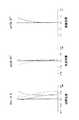
図2乃至図4は数値実施例1の無限遠合焦状態における諸収差図を示し、図2は広角端状態、図3は中間焦点距離状態、図4は望遠端状態における諸収差図を示す。 2 to 4 show various aberration diagrams in the infinite focus state in Numerical Example 1, FIG. 2 shows a wide angle end state, FIG. 3 shows an intermediate focal length state, and FIG. 4 shows various aberration diagrams in a telephoto end state. .
図2乃至図4には、球面収差図において実線はd線(587.56nm)、点線はC線(波長656.3nm)、一点鎖線はg線(波長435.8nm)における値を示すものであり、非点収差図において実線はd線のサジタル像面、破線はd線のメリディオナル像面における値を示すものであり、歪曲収差図において実線はd線における値を示すものである。 In FIG. 2 to FIG. 4, in the spherical aberration diagrams, the solid line indicates the value at the d line (587.56 nm), the dotted line indicates the value at the C line (wavelength 656.3 nm), and the alternate long and short dash line indicates the value at the g line (wavelength 435.8 nm). In the astigmatism diagram, the solid line indicates the value on the sagittal image plane of the d line, the broken line indicates the value on the meridional image plane of the d line, and in the distortion diagram, the solid line indicates the value on the d line.
各収差図から、数値実施例1は諸収差が良好に補正され、優れた結像性能を有していることが明らかである。 From the aberration diagrams, it is clear that Numerical Example 1 has excellent image forming performance with various aberrations corrected well.
<第2の実施の形態>
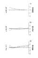
図5は、本技術の第2の実施の形態におけるズームレンズ2のレンズ構成を示している。<Second Embodiment>
FIG. 5 shows a lens configuration of the zoom lens 2 according to the second embodiment of the present technology.
ズームレンズ2は変倍比が1.70倍にされている。 The zoom lens 2 has a zoom ratio of 1.70.
ズームレンズ2は、物体側から像側へ順に、負の屈折力を有する第1レンズ群GR1、正の屈折力を有する第2レンズ群GR2、負の屈折力を有する第3レンズ群GR3、正の屈折力を有する第4レンズ群GR4が配列されて成る。 The zoom lens 2 includes, in order from the object side to the image side, a first lens group GR1 having a negative refractive power, a second lens group GR2 having a positive refractive power, a third lens group GR3 having a negative refractive power, and a positive The fourth lens group GR4 having a refractive power of is arranged.
ズームレンズ2は、広角端状態から望遠端状態への変倍に際し、第1レンズ群GR1と第2レンズ群GR2の間隔が縮小し、第2レンズ群GR2と第3レンズ群GR3の間隔が拡大し、第3レンズ群GR3と第4レンズ群GR4の間隔が縮小するように各レンズ群が光軸方向へ移動される。 When zooming from the wide-angle end state to the telephoto end state, the zoom lens 2 reduces the distance between the first lens group GR1 and the second lens group GR2, and increases the distance between the second lens group GR2 and the third lens group GR3. Then, each lens group is moved in the optical axis direction so that the distance between the third lens group GR3 and the fourth lens group GR4 is reduced.
第1レンズ群GR1は、物体側から像側へ順に、物体側に凸面を向けたメニスカスレンズL1と両凹レンズL2と両凸レンズL3の3枚のレンズによって構成されている。 The first lens group GR1 is composed of three lenses, a meniscus lens L1, a biconcave lens L2, and a biconvex lens L3 having a convex surface facing the object side in order from the object side to the image side.
第2レンズ群GR2は、物体側から像側へ順に、物体側に凸面を向けたメニスカスレンズL4と両凸レンズL5の接合レンズと、物体側に凸面を向けたメニスカスレンズL6と、両凸レンズL7と、像側に凸面を向けたメニスカスレンズL8との5枚のレンズによって構成されている。 The second lens group GR2 includes, in order from the object side to the image side, a cemented lens of a meniscus lens L4 having a convex surface facing the object side and a biconvex lens L5, a meniscus lens L6 having a convex surface facing the object side, and a biconvex lens L7. And a meniscus lens L8 having a convex surface facing the image side.
第2レンズ群GR2は、物体側から像側へ順に配列された第1部分群G2aと第2部分群G2bと第3部分群G2cとから成る。第1部分群G2aはメニスカスレンズL4と両凸レンズL5によって構成され、第2部分群G2bはメニスカスレンズL6によって構成され、第3部分群G2cは両凸レンズL7とメニスカスレンズL8によって構成されている。 The second lens group GR2 includes a first partial group G2a, a second partial group G2b, and a third partial group G2c arranged in order from the object side to the image side. The first partial group G2a is constituted by a meniscus lens L4 and a biconvex lens L5, the second partial group G2b is constituted by a meniscus lens L6, and the third partial group G2c is constituted by a biconvex lens L7 and a meniscus lens L8.
第2部分群G2bは光軸方向に直交する方向へシフト可能な防振レンズ群とされている。 The second partial group G2b is an anti-vibration lens group that can be shifted in a direction orthogonal to the optical axis direction.
第3レンズ群GR3は、両凹レンズL9の1枚のレンズによって構成されている。第3レンズ群GR3は合焦のために光軸方向へ移動可能なフォーカスレンズ群とされている。 The third lens group GR3 is composed of one lens, which is a biconcave lens L9. The third lens group GR3 is a focus lens group that can move in the optical axis direction for focusing.
第4レンズ群GR4は、両凸レンズL10と、像側に凸面を向けたメニスカスレンズL11と両凹レンズL12の接合レンズとの3枚のレンズによって構成されている。 The fourth lens group GR4 includes three lenses, a biconvex lens L10, and a cemented lens of a meniscus lens L11 having a convex surface facing the image side and a biconcave lens L12.
第2レンズ群GR2における第1部分群G2aと第2部分群G2bの間には開口絞りSが配置され、開口絞りSは第2部分群G2と一体になって光軸方向へ移動される。尚、開口絞りSは第2部分群G2bと第3部分群G2cの間に配置されていてもよい。 An aperture stop S is disposed between the first partial group G2a and the second partial group G2b in the second lens group GR2, and the aperture stop S is moved in the optical axis direction integrally with the second partial group G2. The aperture stop S may be disposed between the second partial group G2b and the third partial group G2c.
第4レンズ群GR4と像面IMGの間にはフィルター機能を有するカバーガラスCGが配置されている。 A cover glass CG having a filter function is disposed between the fourth lens group GR4 and the image plane IMG.
表4に、第2の実施の形態におけるズームレンズ2に具体的数値を適用した数値実施例2のレンズデーターを示す。 Table 4 shows lens data of Numerical Example 2 in which specific numerical values are applied to the zoom lens 2 according to the second embodiment.
ズームレンズ2において、第1レンズ群GR1のメニスカスレンズL1の両面(第1面、第2面)、第3レンズ群GR3の両凹レンズL9の像側の面(第18面)、第4レンズ群GR4の両凸レンズL10の像側の面(第20面)及び第4レンズ群GR4の両凹レンズL12の像側の面(第23面)は非球面に形成されている。数値実施例2における非球面の4次、6次、8次、10次の非球面係数A4、A6、A8、A10を円錐定数κと共に表5に示す。 In the zoom lens 2, both surfaces (first and second surfaces) of the meniscus lens L1 of the first lens group GR1, the image side surface (18th surface) of the biconcave lens L9 of the third lens group GR3, and the fourth lens group. The image side surface (20th surface) of the biconvex lens L10 of GR4 and the image side surface (23rd surface) of the biconcave lens L12 of the fourth lens group GR4 are formed as aspherical surfaces. Table 5 shows fourth-order, sixth-order, eighth-order, and tenth-order aspherical coefficients A4, A6, A8, and A10 of the aspherical surface in Numerical Example 2 together with the conic constant κ.
ズームレンズ2において、広角端状態と望遠端状態の間の変倍に際して、第1レンズ群GR1と第2レンズ群GR2の間の面間隔D6、第2レンズ群GR2と第3レンズ群GR3の間の面間隔D16、第3レンズ群GR3と第4レンズ群GR4の間の面間隔D18及び第4レンズ群GR4とカバーガラスCGの間の面間隔D23が変化する。数値実施例2における各面間隔の広角端状態、中間焦点距離状態及び望遠端状態における可変間隔を焦点距離f、FナンバーFno.及び半画角ωとともに表6に示す。 In the zoom lens 2, upon zooming between the wide-angle end state and the telephoto end state, the surface distance D6 between the first lens group GR1 and the second lens group GR2, and between the second lens group GR2 and the third lens group GR3. The surface distance D16, the surface distance D18 between the third lens group GR3 and the fourth lens group GR4, and the surface distance D23 between the fourth lens group GR4 and the cover glass CG change. In the numerical example 2, the variable distances in the wide-angle end state, the intermediate focal length state, and the telephoto end state of each surface interval are expressed as focal length f, F number Fno. And Table 6 together with the half angle of view ω.
図6乃至図8は数値実施例2の無限遠合焦状態における諸収差図を示し、図6は広角端状態、図7は中間焦点距離状態、図8は望遠端状態における諸収差図を示す。 6 to 8 show various aberration diagrams in the infinite focus state in Numerical Example 2, FIG. 6 shows the wide-angle end state, FIG. 7 shows the intermediate focal length state, and FIG. 8 shows the various aberration diagrams in the telephoto end state. .
図6乃至図8には、球面収差図において実線はd線(587.56nm)、点線はC線(波長656.3nm)、一点鎖線はg線(波長435.8nm)における値を示すものであり、非点収差図において実線はd線のサジタル像面、破線はd線のメリディオナル像面における値を示すものであり、歪曲収差図において実線はd線における値を示すものである。 In FIG. 6 to FIG. 8, in the spherical aberration diagrams, the solid line indicates the value at the d line (587.56 nm), the dotted line indicates the value at the C line (wavelength 656.3 nm), and the alternate long and short dash line indicates the value at the g line (wavelength 435.8 nm). In the astigmatism diagram, the solid line indicates the value on the sagittal image plane of the d line, the broken line indicates the value on the meridional image plane of the d line, and in the distortion diagram, the solid line indicates the value on the d line.
各収差図から、数値実施例2は諸収差が良好に補正され、優れた結像性能を有していることが明らかである。 From each aberration diagram, it is clear that Numerical Example 2 has excellent imaging performance with various aberrations corrected well.
<第3の実施の形態>
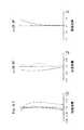
図9は、本技術の第3の実施の形態におけるズームレンズ3のレンズ構成を示している。<Third Embodiment>
FIG. 9 shows a lens configuration of the
ズームレンズ3は変倍比が1.70倍にされている。 The
ズームレンズ3は、物体側から像側へ順に、負の屈折力を有する第1レンズ群GR1、正の屈折力を有する第2レンズ群GR2、負の屈折力を有する第3レンズ群GR3、負の屈折力を有する第4レンズ群GR4が配列されて成る。 The
ズームレンズ3は、広角端状態から望遠端状態への変倍に際し、第1レンズ群GR1と第2レンズ群GR2の間隔が縮小し、第2レンズ群GR2と第3レンズ群GR3の間隔が拡大し、第3レンズ群GR3と第4レンズ群GR4の間隔が縮小するように各レンズ群が光軸方向へ移動される。 When zooming from the wide-angle end state to the telephoto end state, the
第1レンズ群GR1は、物体側から像側へ順に、物体側に凸面を向けたメニスカスレンズL1と両凹レンズL2と両凸レンズL3の3枚のレンズによって構成されている。 The first lens group GR1 is composed of three lenses, a meniscus lens L1, a biconcave lens L2, and a biconvex lens L3 having a convex surface facing the object side in order from the object side to the image side.
第2レンズ群GR2は、物体側から像側へ順に、物体側に凸面を向けたメニスカスレンズL4と両凸レンズL5の接合レンズと、両凸レンズL6と、両凸レンズL7と、像側に凸面を向けたメニスカスレンズL8との5枚のレンズによって構成されている。 The second lens group GR2, in order from the object side to the image side, a cemented lens of a meniscus lens L4 having a convex surface facing the object side and a biconvex lens L5, a biconvex lens L6, a biconvex lens L7, and a convex surface facing the image side. Further, the lens is composed of five lenses including a meniscus lens L8.
第2レンズ群GR2は、物体側から像側へ順に配列された第1部分群G2aと第2部分群G2bと第3部分群G2cとから成る。第1部分群G2aはメニスカスレンズL4と両凸レンズL5によって構成され、第2部分群G2bは両凸レンズL6によって構成され、第3部分群G2cは両凸レンズL7とメニスカスレンズL8によって構成されている。 The second lens group GR2 includes a first partial group G2a, a second partial group G2b, and a third partial group G2c arranged in order from the object side to the image side. The first partial group G2a includes a meniscus lens L4 and a biconvex lens L5, the second partial group G2b includes a biconvex lens L6, and the third partial group G2c includes a biconvex lens L7 and a meniscus lens L8.
第2部分群G2bは光軸方向に直交する方向へシフト可能な防振レンズ群とされている。 The second partial group G2b is an anti-vibration lens group that can be shifted in a direction orthogonal to the optical axis direction.
第3レンズ群GR3は、メニスカスレンズL9の1枚のレンズによって構成されている。第3レンズ群GR3は合焦のために光軸方向へ移動可能なフォーカスレンズ群とされている。 The third lens group GR3 is configured by one lens of the meniscus lens L9. The third lens group GR3 is a focus lens group that can move in the optical axis direction for focusing.
第4レンズ群GR4は、像側に凸面を向けた凸レンズL10と、両凸レンズL11と物体側に凹面を向けたメニスカスレンズL12との接合レンズとの3枚のレンズによって構成されている。 The fourth lens group GR4 includes three lenses including a convex lens L10 having a convex surface facing the image side, and a cemented lens of a biconvex lens L11 and a meniscus lens L12 having a concave surface facing the object side.
第2レンズ群GR2における第1部分群G2aと第2部分群G2bの間には開口絞りSが配置され、開口絞りSは第2部分群G2と一体になって光軸方向へ移動される。尚、開口絞りSは第2部分群G2bと第3部分群G2cの間に配置されていてもよい。 An aperture stop S is disposed between the first partial group G2a and the second partial group G2b in the second lens group GR2, and the aperture stop S is moved in the optical axis direction integrally with the second partial group G2. The aperture stop S may be disposed between the second partial group G2b and the third partial group G2c.
第4レンズ群GR4と像面IMGの間にはフィルター機能を有するカバーガラスCGが配置されている。 A cover glass CG having a filter function is disposed between the fourth lens group GR4 and the image plane IMG.
表7に、第3の実施の形態におけるズームレンズ3に具体的数値を適用した数値実施例3のレンズデーターを示す。 Table 7 shows lens data of a numerical example 3 in which specific numerical values are applied to the
ズームレンズ3において、第1レンズ群GR1のメニスカスレンズL1の両面(第1面、第2面)、第3レンズ群GR3のメニスカスレンズL9の像側の面(第18面)、第4レンズ群GR4の凸レンズL10の像側の面(第20面)及び第4レンズ群GR4のメニスカスレンズL12の像側の面(第23面)は非球面に形成されている。数値実施例3における非球面の4次、6次、8次、10次の非球面係数A4、A6、A8、A10を円錐定数κと共に表8に示す。 In the
ズームレンズ3において、広角端状態と望遠端状態の間の変倍に際して、第1レンズ群GR1と第2レンズ群GR2の間の面間隔D6、第2レンズ群GR2と第3レンズ群GR3の間の面間隔D16、第3レンズ群GR3と第4レンズ群GR4の間の面間隔D18及び第4レンズ群GR4とカバーガラスCGの間の面間隔D23が変化する。数値実施例3における各面間隔の広角端状態、中間焦点距離状態及び望遠端状態における可変間隔を焦点距離f、FナンバーFno.及び半画角ωとともに表9に示す。 In the
図10乃至図12は数値実施例3の無限遠合焦状態における諸収差図を示し、図10は広角端状態、図11は中間焦点距離状態、図12は望遠端状態における諸収差図を示す。 FIGS. 10 to 12 show various aberration diagrams in the infinite focus state of Numerical Example 3, FIG. 10 shows the wide-angle end state, FIG. 11 shows the intermediate focal length state, and FIG. 12 shows the various aberration diagrams in the telephoto end state. .
図10乃至図12には、球面収差図において実線はd線(587.56nm)、点線はC線(波長656.3nm)、一点鎖線はg線(波長435.8nm)における値を示すものであり、非点収差図において実線はd線のサジタル像面、破線はd線のメリディオナル像面における値を示すものであり、歪曲収差図において実線はd線における値を示すものである。 In FIG. 10 to FIG. 12, in the spherical aberration diagrams, the solid line indicates the value at the d line (587.56 nm), the dotted line indicates the value at the C line (wavelength 656.3 nm), and the alternate long and short dash line indicates the value at the g line (wavelength 435.8 nm). In the astigmatism diagram, the solid line indicates the value on the sagittal image plane of the d line, the broken line indicates the value on the meridional image plane of the d line, and in the distortion diagram, the solid line indicates the value on the d line.
各収差図から、数値実施例3は諸収差が良好に補正され、優れた結像性能を有していることが明らかである。 From each aberration diagram, it is clear that Numerical Example 3 has excellent imaging performance with various aberrations corrected well.
[ズームレンズの条件式の各値]
以下に、本技術ズームレンズの条件式の各値について説明する。[Each value of conditional expression of zoom lens]
Hereinafter, each value of the conditional expression of the zoom lens according to the present technology will be described.
表10にズームレンズ1乃至ズームレンズ3における前記条件式(1)及び条件式(2)の各値を示す。 Table 10 shows values of the conditional expression (1) and the conditional expression (2) in the
表10から明らかなように、ズームレンズ1乃至ズームレンズ3は条件式(1)及び条件式(2)を満足するようにされている。 As is apparent from Table 10, the
[撮像装置の構成]
本技術撮像装置は、ズームレンズが、物体側から像側へ順に配置された負の屈折力を有する第1レンズ群と正の屈折力を有する第2レンズ群と負の屈折力を有する第3レンズ群と第4レンズ群を備え、広角端状態から望遠端状態への変倍に際し、前記第1レンズ群と前記第2レンズ群の間隔が縮小し、前記第2レンズ群と前記第3レンズ群の間隔が拡大し、前記第3レンズ群と前記第4レンズ群の間隔が縮小し、以下の条件式(1)を満足する。
(1)f2〜4/fw<3.0
但し、
f2〜4:第2レンズ群から第4レンズ群までの合成焦点距離
fw:広角端状態におけるレンズ全系の焦点距離
とする。[Configuration of imaging device]
In the imaging apparatus according to the present technology, the zoom lens includes a first lens group having a negative refractive power, a second lens group having a positive refractive power, and a third lens having a negative refractive power, which are arranged in order from the object side to the image side. A lens group and a fourth lens group, wherein the distance between the first lens group and the second lens group is reduced upon zooming from the wide-angle end state to the telephoto end state, and the second lens group and the third lens The distance between the groups is increased, and the distance between the third lens group and the fourth lens group is reduced, and the following conditional expression (1) is satisfied.
(1) f2-4 / fw <3.0
However,
f2-4: The combined focal length fw from the second lens group to the fourth lens group fw: the focal length of the entire lens system in the wide-angle end state.
条件式(1)は、広角端状態におけるレンズ全系の屈折力と第2レンズ群から第4レンズ群までの屈折力との関係を規定する式である。 Conditional expression (1) defines the relationship between the refractive power of the entire lens system in the wide-angle end state and the refractive power from the second lens group to the fourth lens group.
条件式(1)を満たさない場合には、変倍時の光軸方向における可動レンズ群のストロークが長くなりレンズ系の全長が長くなって小型化が阻害されてしまう。 When the conditional expression (1) is not satisfied, the stroke of the movable lens group in the optical axis direction at the time of zooming becomes long, and the total length of the lens system becomes long, so that downsizing is hindered.
従って、撮像装置のズームレンズが条件式(1)を満足することにより、変倍時の光軸方向における可動レンズ群のストロークが短縮化され、小型化を図ることができる。 Therefore, when the zoom lens of the image pickup apparatus satisfies the conditional expression (1), the stroke of the movable lens group in the optical axis direction at the time of zooming can be shortened and the size can be reduced.
尚、本技術左有象装置においては、以下の条件式(1)′を満足することがより好ましい。
(1)′f2〜4/fw<2.7
撮像装置のズームレンズが条件式(1)′を満足することにより、変倍時の光軸方向における可動レンズ群のストロークが一層短縮化され、一層の小型化を図ることができる。In the left object apparatus of the present technology, it is more preferable that the following conditional expression (1) ′ is satisfied.
(1) 'f2-4 / fw <2.7
When the zoom lens of the imaging apparatus satisfies the conditional expression (1) ′, the stroke of the movable lens group in the optical axis direction at the time of zooming can be further shortened, and further miniaturization can be achieved.
また、本技術撮像装置においては、以下の条件式(1)′′を満足することがより一層好ましい。
(1)′′f2〜4/fw<2.4
撮像装置のズームレンズが条件式(1)′′を満足することにより、変倍時の光軸方向における可動レンズ群のストロークがより一層短縮化され、より一層の小型化を図ることができる。In the imaging device of the present technology, it is even more preferable that the following conditional expression (1) ″ is satisfied.
(1) "f2-4 / fw <2.4
When the zoom lens of the imaging apparatus satisfies the conditional expression (1) ″, the stroke of the movable lens group in the optical axis direction at the time of zooming can be further shortened, and further miniaturization can be achieved.
[撮像装置の一実施形態]
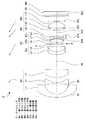
図13に、本技術撮像装置の一実施形態による交換レンズ式のデジタルカメラのブロック図を示す。[One Embodiment of Imaging Device]
FIG. 13 is a block diagram of an interchangeable lens type digital camera according to an embodiment of the imaging apparatus of the present technology.
撮像装置(デジタルカメラ)100は、撮像機能を担うカメラブロック10と、撮影された画像信号のアナログ−デジタル変換等の信号処理を行うカメラ信号処理部20と、画像信号の記録再生処理を行う画像処理部30とを有している。また、撮像装置100は、撮影された画像等を表示するLCD(Liquid Crystal Display)等の表示部40と、メモリーカード1000への画像信号の書込及び読出を行うR/W(リーダ/ライタ)50と、撮像装置の全体を制御するCPU(Central Processing Unit)60と、ユーザーによって所要の操作が行われる各種のスイッチ等から成る入力部70と、カメラブロック10に配置されたレンズの駆動を制御するレンズ駆動制御部80とを備えている。 An imaging apparatus (digital camera) 100 includes a
カメラブロック10は、例えば、交換レンズに備えられ、ズームレンズ11(本技術が適用されるズームレンズ1、2、3)を含む光学系や、CCD(Charge Coupled Device)やCMOS(Complementary Metal Oxide Semiconductor)等の撮像素子12等とによって構成されている。 The
カメラ信号処理部20は、撮像素子12からの出力信号に対するデジタル信号への変換、ノイズ除去、画質補正、輝度・色差信号への変換等の各種の信号処理を行う。 The camera
画像処理部30は、所定の画像データーフォーマットに基づく画像信号の圧縮符号化・伸張復号化処理や解像度等のデーター仕様の変換処理等を行う。 The
表示部40はユーザーの入力部70に対する操作状態や撮影した画像等の各種のデーターを表示する機能を有している。 The
R/W50は、画像処理部30によって符号化された画像データーのメモリーカード1000への書込及びメモリーカード1000に記録された画像データーの読出を行う。 The R /
CPU60は、撮像装置100に設けられた各回路ブロックを制御する制御処理部として機能し、入力部70からの指示入力信号等に基づいて各回路ブロックを制御する。 The
入力部70は、例えば、シャッター操作を行うためのシャッターレリーズボタンや、動作モードを選択するための選択スイッチ等によって構成され、ユーザーによる操作に応じた指示入力信号をCPU60に対して出力する。 The
レンズ駆動制御部80は、CPU60からの制御信号に基づいてズームレンズ11の各レンズを駆動する図示しないモータ等を制御する。 The lens
メモリーカード1000は、例えば、R/W50に接続されたスロットに対して着脱可能な半導体メモリーである。 The
以下に、撮像装置100における動作を説明する。 Hereinafter, an operation in the
撮影の待機状態では、CPU60による制御の下で、カメラブロック10において撮影された画像信号が、カメラ信号処理部20を介して表示部40に出力され、カメラスルー画像として表示される。また、入力部70からのズーミングのための指示入力信号が入力されると、CPU60がレンズ駆動制御部80に制御信号を出力し、レンズ駆動制御部80の制御に基づいてズームレンズ11の所定のレンズが移動される。 In the shooting standby state, under the control of the
入力部70からの指示入力信号によりカメラブロック10の図示しないシャッターが動作されると、撮影された画像信号がカメラ信号処理部20から画像処理部30に出力されて圧縮符号化処理され、所定のデーターフォーマットのデジタルデーターに変換される。変換されたデーターはR/W50に出力され、メモリーカード1000に書き込まれる。 When a shutter (not shown) of the
フォーカシングは、例えば、入力部70のシャッターレリーズボタンが半押しされた場合や記録(撮影)のために全押しされた場合等に、CPU60からの制御信号に基づいてレンズ駆動制御部80がズームレンズ11の所定のレンズを移動させることにより行われる。 In focusing, for example, when the shutter release button of the
メモリーカード1000に記録された画像データーを再生する場合には、入力部70に対する操作に応じて、R/W50によってメモリーカード1000から所定の画像データーが読み出され、画像処理部30によって伸張復号化処理が行われた後、再生画像信号が表示部40に出力されて再生画像が表示される。 When reproducing the image data recorded on the
[その他]
本技術ズームレンズ及び本技術撮像装置においては、第1レンズ群乃至第4レンズ群に加えて屈折力を有さないレンズや絞り等の他の光学要素が配置されていてもよい。この場合において、本技術ズームレンズのレンズ構成は第1レンズ群乃至第4レンズ群の実質的に4群のレンズ構成にされている。[Others]
In the zoom lens and the imaging device of the present technology, in addition to the first lens group to the fourth lens group, other optical elements such as a lens having no refractive power and a diaphragm may be disposed. In this case, the lens configuration of the zoom lens according to the present technology is substantially a four-unit lens configuration of the first lens unit to the fourth lens unit.
[本技術]
本技術は、以下の構成にすることもできる。[Technology]
The present technology may be configured as follows.
<1>物体側から像側へ順に配置された負の屈折力を有する第1レンズ群と正の屈折力を有する第2レンズ群と負の屈折力を有する第3レンズ群と第4レンズ群を備え、広角端状態から望遠端状態への変倍に際し、前記第1レンズ群と前記第2レンズ群の間隔が縮小し、前記第2レンズ群と前記第3レンズ群の間隔が拡大し、前記第3レンズ群と前記第4レンズ群の間隔が縮小し、以下の条件式(1)を満足するズームレンズ。
(1)f2〜4/fw<3.0
但し、
f2〜4:第2レンズ群から第4レンズ群までの合成焦点距離
fw:広角端状態におけるレンズ全系の焦点距離
とする。<1> A first lens group having a negative refractive power, a second lens group having a positive refractive power, a third lens group having a negative refractive power, and a fourth lens group, which are disposed in order from the object side to the image side. And during zooming from the wide-angle end state to the telephoto end state, the distance between the first lens group and the second lens group is reduced, and the distance between the second lens group and the third lens group is increased, A zoom lens in which an interval between the third lens group and the fourth lens group is reduced and satisfies the following conditional expression (1).
(1) f2-4 / fw <3.0
However,
f2-4: The combined focal length fw from the second lens group to the fourth lens group fw: the focal length of the entire lens system in the wide-angle end state.
<2>前記第2レンズ群は物体側から像側へ順に配置された第1部分群と第2部分群と第3部分群によって構成され、前記第2部分群が光軸方向に直交する方向へシフト可能な防振レンズ群とされ、以下の条件式(2)を満足する前記<1>に記載のズームレンズ。
(2)1.0<f2b/f2<6.0
但し、
f2b:第2部分群の焦点距離
f2:第2レンズ群の焦点距離
とする。<2> The second lens group includes a first partial group, a second partial group, and a third partial group that are arranged in order from the object side to the image side, and the second partial group is a direction orthogonal to the optical axis direction. The zoom lens according to <1>, wherein the zoom lens group is capable of shifting to a position, and satisfies the following conditional expression (2).
(2) 1.0 <f2b / f2 <6.0
However,
f2b: focal length of the second partial group f2: focal length of the second lens group.
<3>前記第3レンズ群が合焦のために光軸方向へ移動可能なフォーカスレンズ群とされた前記<1>又は前記<2>に記載のズームレンズ。 <3> The zoom lens according to <1> or <2>, wherein the third lens group is a focus lens group movable in an optical axis direction for focusing.
<4>前記第3レンズ群が1枚のレンズによって構成された前記<3>に記載のズームレンズ。 <4> The zoom lens according to <3>, wherein the third lens group includes one lens.
<5>前記第2レンズ群の最も物体側に配置されたレンズから前記第2レンズ群の最も像側に配置されたレンズまでの間に開口絞りが配置された前記<1>から前記<4>の何れかに記載のズームレンズ。 <5> An aperture stop is disposed between a lens disposed on the most object side of the second lens group and a lens disposed on the most image side of the second lens group. <1> to <4 > The zoom lens according to any one of the above.
<6>前記第4レンズ群にg線、d線における正常分散直線からのずれ量である異常分散性の値が正の凸レンズと負の凹レンズとが少なくとも1枚ずつ配置された前記<1>から前記<5>の何れかに記載のズームレンズ。 <6> In the fourth lens group, at least one positive lens and one negative concave lens having anomalous dispersion value which is a deviation amount from the normal dispersion line in the g-line and the d-line are arranged in the <1>. To a zoom lens according to any one of <5>.
<7>ズームレンズと前記ズームレンズによって形成された光学像を電気的信号に変換する撮像素子とを備え、前記ズームレンズは、物体側から像側へ順に配置された負の屈折力を有する第1レンズ群と正の屈折力を有する第2レンズ群と負の屈折力を有する第3レンズ群と第4レンズ群を備え、広角端状態から望遠端状態への変倍に際し、前記第1レンズ群と前記第2レンズ群の間隔が縮小し、前記第2レンズ群と前記第3レンズ群の間隔が拡大し、前記第3レンズ群と前記第4レンズ群の間隔が縮小し、以下の条件式(1)を満足する撮像装置。
(1)f2〜4/fw<3.0
但し、
f2〜4:第2レンズ群から第4レンズ群までの合成焦点距離
fw:広角端状態におけるレンズ全系の焦点距離
とする。<7> A zoom lens and an image sensor that converts an optical image formed by the zoom lens into an electrical signal, wherein the zoom lens has a negative refractive power arranged in order from the object side to the image side. A first lens group, a second lens group having a positive refractive power, a third lens group having a negative refractive power, and a fourth lens group, and the first lens at the time of zooming from the wide-angle end state to the telephoto end state The distance between the second lens group and the second lens group is reduced, the distance between the second lens group and the third lens group is enlarged, and the distance between the third lens group and the fourth lens group is reduced. An imaging device that satisfies Expression (1).
(1) f2-4 / fw <3.0
However,
f2-4: The combined focal length fw from the second lens group to the fourth lens group fw: the focal length of the entire lens system in the wide-angle end state.
<8>実質的にレンズパワーを有さないレンズを含む光学要素がさらに配置されている前記<1>から前記<6>の何れかに記載のズームレンズ又は前記<7>に記載の撮像装置。 <8> The zoom lens according to any one of <1> to <6> or the imaging device according to <7>, further including an optical element including a lens having substantially no lens power. .
尚、上記した実施の形態においては、撮像装置を交換式のデジタルカメラに適用した例を示したが、撮像装置の適用範囲は交換式のデジタルカメラに限られることはなく、デジタルスチルカメラ、デジタルビデオカメラ、カメラが組み込まれた携帯電話、カメラが組み込まれたPDA(Personal Digital Assistant)等のデジタル入出力機器のカメラ部等として広く適用することができる。 In the above-described embodiment, an example in which the imaging device is applied to an interchangeable digital camera has been described. However, the application range of the imaging device is not limited to the interchangeable digital camera, and a digital still camera, digital The present invention can be widely applied as a camera unit of a digital input / output device such as a video camera, a mobile phone incorporating a camera, or a PDA (Personal Digital Assistant) incorporating a camera.
上記した各実施の形態において示した各部の形状及び数値は、何れも本技術を実施するための具体化のほんの一例に過ぎず、これらによって本技術の技術的範囲が限定的に解釈されることがあってはならないものである。 The shapes and numerical values of the respective parts shown in the above-described embodiments are merely examples of specific embodiments for carrying out the present technology, and the technical scope of the present technology is limitedly interpreted by these. There should not be.
1…ズームレンズ、2…ズームレンズ、3…ズームレンズ、GR1…第1レンズ群、GR2…第2レンズ群、GR3…第3レンズ群、GR4…第4レンズ群、G2a…第1部分群、G2b…第2部分群、G2c…第3部分群、100…撮像装置、11…ズームレンズ、12…撮像素子 DESCRIPTION OF
Claims (7)
Translated fromJapanese広角端状態から望遠端状態への変倍に際し、前記第1レンズ群と前記第2レンズ群の間隔が縮小し、前記第2レンズ群と前記第3レンズ群の間隔が拡大し、前記第3レンズ群と前記第4レンズ群の間隔が縮小し、
以下の条件式(1)を満足する
ズームレンズ。
(1)f2〜4/fw<3.0
但し、
f2〜4:第2レンズ群から第4レンズ群までの合成焦点距離
fw:広角端状態におけるレンズ全系の焦点距離
とする。A first lens group having a negative refractive power, a second lens group having a positive refractive power, a third lens group having a negative refractive power, and a fourth lens group, which are arranged in order from the object side to the image side;
Upon zooming from the wide-angle end state to the telephoto end state, the distance between the first lens group and the second lens group is reduced, the distance between the second lens group and the third lens group is increased, and the third lens group is increased. The distance between the lens group and the fourth lens group is reduced,
A zoom lens that satisfies the following conditional expression (1).
(1) f2-4 / fw <3.0
However,
f2-4: The combined focal length fw from the second lens group to the fourth lens group fw: the focal length of the entire lens system in the wide-angle end state.
前記第2部分群が光軸方向に直交する方向へシフト可能な防振レンズ群とされ、
以下の条件式(2)を満足する
請求項1に記載のズームレンズ。
(2)1.0<f2b/f2<6.0
但し、
f2b:第2部分群の焦点距離
f2:第2レンズ群の焦点距離
とする。The second lens group includes a first partial group, a second partial group, and a third partial group that are arranged in order from the object side to the image side,
The second portion group is an anti-vibration lens group capable of shifting in a direction perpendicular to the optical axis direction,
The zoom lens according to claim 1, wherein the following conditional expression (2) is satisfied.
(2) 1.0 <f2b / f2 <6.0
However,
f2b: focal length of the second partial group f2: focal length of the second lens group.
請求項1に記載のズームレンズ。The zoom lens according to claim 1, wherein the third lens group is a focus lens group movable in an optical axis direction for focusing.
請求項3に記載のズームレンズ。The zoom lens according to claim 3, wherein the third lens group includes one lens.
請求項1に記載のズームレンズ。The zoom lens according to claim 1, wherein an aperture stop is disposed between a lens disposed closest to the object side of the second lens group and a lens disposed closest to the image side of the second lens group.
請求項1に記載のズームレンズ。2. The zoom according to claim 1, wherein at least one convex lens and one negative concave lens each having a positive value of anomalous dispersion that is a deviation amount from a normal dispersion line in the g-line and the d-line are arranged in the fourth lens group. lens.
前記ズームレンズは、
物体側から像側へ順に配置された負の屈折力を有する第1レンズ群と正の屈折力を有する第2レンズ群と負の屈折力を有する第3レンズ群と第4レンズ群を備え、
広角端状態から望遠端状態への変倍に際し、前記第1レンズ群と前記第2レンズ群の間隔が縮小し、前記第2レンズ群と前記第3レンズ群の間隔が拡大し、前記第3レンズ群と前記第4レンズ群の間隔が縮小し、
以下の条件式(1)を満足する
撮像装置。
(1)f2〜4/fw<3.0
但し、
f2〜4:第2レンズ群から第4レンズ群までの合成焦点距離
fw:広角端状態におけるレンズ全系の焦点距離
とする。A zoom lens and an image sensor that converts an optical image formed by the zoom lens into an electrical signal;
The zoom lens is
A first lens group having a negative refractive power, a second lens group having a positive refractive power, a third lens group having a negative refractive power, and a fourth lens group, which are arranged in order from the object side to the image side;
Upon zooming from the wide-angle end state to the telephoto end state, the distance between the first lens group and the second lens group is reduced, the distance between the second lens group and the third lens group is increased, and the third lens group is increased. The distance between the lens group and the fourth lens group is reduced,
An imaging apparatus that satisfies the following conditional expression (1).
(1) f2-4 / fw <3.0
However,
f2-4: The combined focal length fw from the second lens group to the fourth lens group fw: the focal length of the entire lens system in the wide-angle end state.
Priority Applications (1)
| Application Number | Priority Date | Filing Date | Title |
|---|---|---|---|
| JP2012044277AJP2013182054A (en) | 2012-02-29 | 2012-02-29 | Zoom lens and image capturing device |
Applications Claiming Priority (1)
| Application Number | Priority Date | Filing Date | Title |
|---|---|---|---|
| JP2012044277AJP2013182054A (en) | 2012-02-29 | 2012-02-29 | Zoom lens and image capturing device |
Publications (1)
| Publication Number | Publication Date |
|---|---|
| JP2013182054Atrue JP2013182054A (en) | 2013-09-12 |
Family
ID=49272750
Family Applications (1)
| Application Number | Title | Priority Date | Filing Date |
|---|---|---|---|
| JP2012044277APendingJP2013182054A (en) | 2012-02-29 | 2012-02-29 | Zoom lens and image capturing device |
Country Status (1)
| Country | Link |
|---|---|
| JP (1) | JP2013182054A (en) |
Cited By (17)
| Publication number | Priority date | Publication date | Assignee | Title |
|---|---|---|---|---|
| JP2014048370A (en)* | 2012-08-30 | 2014-03-17 | Nikon Corp | Variable power optical system, optical device including the variable power optical system, and method for manufacturing the variable power optical system |
| JP2014048372A (en)* | 2012-08-30 | 2014-03-17 | Nikon Corp | Variable power optical system, optical device including the variable power optical system, and method for manufacturing the variable power optical system |
| JP2014048373A (en)* | 2012-08-30 | 2014-03-17 | Nikon Corp | Variable power optical system, optical device including the variable power optical system, and method for manufacturing the variable power optical system |
| WO2015016031A1 (en)* | 2013-08-02 | 2015-02-05 | 株式会社ニコン | Zoom lens, optical device, and method for producing zoom lens |
| JP2015031951A (en)* | 2014-03-11 | 2015-02-16 | 株式会社ニコン | Zoom lens, optical device, and zoom lens manufacturing method |
| JP2015031869A (en)* | 2013-08-05 | 2015-02-16 | キヤノン株式会社 | Zoom lens and imaging apparatus including the same |
| JP2015045839A (en)* | 2013-08-02 | 2015-03-12 | 株式会社ニコン | Zoom lens, optical device, and zoom lens manufacturing method |
| JP2015172694A (en)* | 2014-03-12 | 2015-10-01 | 株式会社ニコン | Zoom lens, optical device, and method for manufacturing zoom lens |
| CN105556368A (en)* | 2013-08-02 | 2016-05-04 | 株式会社尼康 | Zoom lens, optical device and method for manufacturing zoom lens |
| JP2016126282A (en)* | 2015-01-08 | 2016-07-11 | 株式会社タムロン | Wide-angle zoom lens and imaging apparatus |
| JP2017054083A (en)* | 2015-09-11 | 2017-03-16 | 株式会社ニコン | OPTICAL SYSTEM, OPTICAL DEVICE, AND OPTICAL SYSTEM MANUFACTURING METHOD |
| JP2017161568A (en)* | 2016-03-07 | 2017-09-14 | キヤノン株式会社 | Zoom lens and imaging apparatus having the same |
| US10156696B2 (en) | 2016-09-29 | 2018-12-18 | Fujifilm Corporation | Imaging lens and imaging apparatus |
| US10215972B2 (en) | 2016-09-14 | 2019-02-26 | Canon Kabushiki Kaisha | Optical system and image pickup apparatus including the same |
| JP2019066654A (en)* | 2017-09-29 | 2019-04-25 | キヤノン株式会社 | Zoom lens and imaging device |
| WO2020012639A1 (en)* | 2018-07-13 | 2020-01-16 | 株式会社ニコン | Variable power optical system, optical apparatus, and production method for variable power optical system |
| JP2021135458A (en)* | 2020-02-28 | 2021-09-13 | 株式会社タムロン | Zoom lens and imaging device |
- 2012
- 2012-02-29JPJP2012044277Apatent/JP2013182054A/enactivePending
Cited By (23)
| Publication number | Priority date | Publication date | Assignee | Title |
|---|---|---|---|---|
| JP2014048370A (en)* | 2012-08-30 | 2014-03-17 | Nikon Corp | Variable power optical system, optical device including the variable power optical system, and method for manufacturing the variable power optical system |
| JP2014048372A (en)* | 2012-08-30 | 2014-03-17 | Nikon Corp | Variable power optical system, optical device including the variable power optical system, and method for manufacturing the variable power optical system |
| JP2014048373A (en)* | 2012-08-30 | 2014-03-17 | Nikon Corp | Variable power optical system, optical device including the variable power optical system, and method for manufacturing the variable power optical system |
| JP2015045839A (en)* | 2013-08-02 | 2015-03-12 | 株式会社ニコン | Zoom lens, optical device, and zoom lens manufacturing method |
| US10670847B2 (en) | 2013-08-02 | 2020-06-02 | Nikon Corporation | Zoom lens, optical apparatus, and method for manufacturing the zoom lens |
| CN105556368A (en)* | 2013-08-02 | 2016-05-04 | 株式会社尼康 | Zoom lens, optical device and method for manufacturing zoom lens |
| WO2015016031A1 (en)* | 2013-08-02 | 2015-02-05 | 株式会社ニコン | Zoom lens, optical device, and method for producing zoom lens |
| US11428913B2 (en) | 2013-08-02 | 2022-08-30 | Nikon Corporation | Zoom lens, optical apparatus, and method for manufacturing the zoom lens |
| CN105556368B (en)* | 2013-08-02 | 2018-04-10 | 株式会社尼康 | Zoom lens, optical device and method for manufacturing zoom lens |
| US9939621B2 (en) | 2013-08-02 | 2018-04-10 | Nikon Corporation | Zoom lens, optical apparatus, and method for manufacturing the zoom lens |
| JP2015031869A (en)* | 2013-08-05 | 2015-02-16 | キヤノン株式会社 | Zoom lens and imaging apparatus including the same |
| JP2015031951A (en)* | 2014-03-11 | 2015-02-16 | 株式会社ニコン | Zoom lens, optical device, and zoom lens manufacturing method |
| JP2015172694A (en)* | 2014-03-12 | 2015-10-01 | 株式会社ニコン | Zoom lens, optical device, and method for manufacturing zoom lens |
| JP2016126282A (en)* | 2015-01-08 | 2016-07-11 | 株式会社タムロン | Wide-angle zoom lens and imaging apparatus |
| JP2017054083A (en)* | 2015-09-11 | 2017-03-16 | 株式会社ニコン | OPTICAL SYSTEM, OPTICAL DEVICE, AND OPTICAL SYSTEM MANUFACTURING METHOD |
| JP2017161568A (en)* | 2016-03-07 | 2017-09-14 | キヤノン株式会社 | Zoom lens and imaging apparatus having the same |
| US10215972B2 (en) | 2016-09-14 | 2019-02-26 | Canon Kabushiki Kaisha | Optical system and image pickup apparatus including the same |
| US10156696B2 (en) | 2016-09-29 | 2018-12-18 | Fujifilm Corporation | Imaging lens and imaging apparatus |
| JP2019066654A (en)* | 2017-09-29 | 2019-04-25 | キヤノン株式会社 | Zoom lens and imaging device |
| JP6991814B2 (en) | 2017-09-29 | 2022-01-13 | キヤノン株式会社 | Zoom lens and image pickup device |
| WO2020012639A1 (en)* | 2018-07-13 | 2020-01-16 | 株式会社ニコン | Variable power optical system, optical apparatus, and production method for variable power optical system |
| JP2021135458A (en)* | 2020-02-28 | 2021-09-13 | 株式会社タムロン | Zoom lens and imaging device |
| JP7542965B2 (en) | 2020-02-28 | 2024-09-02 | 株式会社タムロン | Zoom lens and imaging device |
Similar Documents
| Publication | Publication Date | Title |
|---|---|---|
| JP6136588B2 (en) | Zoom lens and imaging device | |
| JP5880365B2 (en) | Imaging lens and imaging apparatus | |
| JP5040408B2 (en) | Zoom lens and imaging device | |
| JP5387392B2 (en) | Zoom lens and imaging device | |
| JP4771182B2 (en) | Zoom lens and imaging device | |
| JP4059228B2 (en) | Zoom lens and imaging device | |
| JP2013182054A (en) | Zoom lens and image capturing device | |
| JP2011237588A (en) | Zoom lens and imaging device | |
| WO2016056310A1 (en) | Wide angle lens and image pickup device | |
| JPWO2018139160A1 (en) | Zoom lens and imaging device | |
| JP5888137B2 (en) | Zoom lens and imaging device | |
| JP2011209347A (en) | Zoom lens and imaging apparatus | |
| JP2011128445A (en) | Zoom lens and image pickup apparatus | |
| JP5891860B2 (en) | Zoom lens and imaging device | |
| JP2013182259A (en) | Zoom lens and image capturing device | |
| JP2012128116A (en) | Zoom lens and imaging apparatus | |
| JP2015064492A (en) | Zoom lens and imaging apparatus | |
| JP2013148780A (en) | Zoom lens and image pickup apparatus | |
| JP2014211468A (en) | Zoom lens and imaging apparatus | |
| JP2012173298A (en) | Zoom lens and imaging apparatus | |
| JP2009217167A (en) | Zoom optical system and imaging apparatus | |
| JP5141375B2 (en) | Zoom lens and imaging device | |
| JP2014066945A (en) | Zoom lens and imaging device | |
| JP6287647B2 (en) | Zoom lens and imaging device | |
| JP2012194280A (en) | Zoom lens and imaging apparatus |