JP2013179355A - Waterproof housing structure and electronic apparatus - Google Patents
Waterproof housing structure and electronic apparatusDownload PDFInfo
- Publication number
- JP2013179355A JP2013179355AJP2013119073AJP2013119073AJP2013179355AJP 2013179355 AJP2013179355 AJP 2013179355AJP 2013119073 AJP2013119073 AJP 2013119073AJP 2013119073 AJP2013119073 AJP 2013119073AJP 2013179355 AJP2013179355 AJP 2013179355A
- Authority
- JP
- Japan
- Prior art keywords
- case
- waterproof
- packing
- connector
- circuit board
- Prior art date
- Legal status (The legal status is an assumption and is not a legal conclusion. Google has not performed a legal analysis and makes no representation as to the accuracy of the status listed.)
- Pending
Links
- 239000000758substrateSubstances0.000claimsabstractdescription67
- 238000004078waterproofingMethods0.000claimsdescription25
- 238000012856packingMethods0.000description91
- 238000000465mouldingMethods0.000description12
- 239000002390adhesive tapeSubstances0.000description7
- 239000002184metalSubstances0.000description4
- 238000004891communicationMethods0.000description3
- 230000000694effectsEffects0.000description3
- 238000009423ventilationMethods0.000description3
- 230000001413cellular effectEffects0.000description2
- 239000012528membraneSubstances0.000description2
- 230000002093peripheral effectEffects0.000description2
- 230000035945sensitivityEffects0.000description2
- 239000000853adhesiveSubstances0.000description1
- 230000001070adhesive effectEffects0.000description1
- 230000003139buffering effectEffects0.000description1
- 230000006835compressionEffects0.000description1
- 238000007906compressionMethods0.000description1
- 238000003780insertionMethods0.000description1
- 230000037431insertionEffects0.000description1
- 239000004973liquid crystal related substanceSubstances0.000description1
- 238000012986modificationMethods0.000description1
- 230000004048modificationEffects0.000description1
- 230000000149penetrating effectEffects0.000description1
Images


Landscapes
- Casings For Electric Apparatus (AREA)
- Telephone Set Structure (AREA)
Abstract
Description
Translated fromJapanese本発明は、組み合わされる複数のケースの間を防水する防水筐体構造と、その防水筐体構造を備える電子機器に関する。 The present invention relates to a waterproof housing structure that waterproofs between a plurality of cases to be combined, and an electronic device including the waterproof housing structure.
折り畳み型携帯端末において、複数のケースを組み合わせる筐体であって、ケース間にパッキンを挟み込んで防水を図るとともに、折り畳まれる他の筐体と電気的接続するフレキシブルプリント回路基板の防水を図った防水筐体構造が特許文献1に開示される。 In a foldable mobile terminal, a case that combines a plurality of cases, with a packing sandwiched between the cases for waterproofing and waterproofing for a flexible printed circuit board that is electrically connected to other folded cases A housing structure is disclosed in
ところで、特許文献1のように、筐体の防水を図るためには、フレキシブルプリント回路基板を含むケース間にパッキンが必要であった。 By the way, as in
本発明の課題は、組み合わされる複数のケースの間を防水する防水筐体構造において、ケース間の防水と、電子基板部の側面から引き出される配線部の防水を簡単な構成で容易に行えるようにすることである。 An object of the present invention is to provide a waterproof housing structure for waterproofing between a plurality of combined cases so that waterproofing between cases and waterproofing of a wiring part drawn out from a side surface of an electronic board part can be easily performed with a simple configuration. It is to be.
以上の課題を解決するため、本発明に係る防水筐体構造は、
第一のケースと、
前記第一のケースと組み合わせられる第二のケースと、
前記第一のケースと前記第二のケースとの間に収納される電子基板部と、
前記電子基板部の側面から引き出された配線部と、
前記電子基板部の第一のケース側の面に全周にわたって一体的に設けられた第一の防水部材と、
前記第一のケースと前記電子基板部との間に設けられ、第二のケース側の面と前記電子基板部との間に前記第一の防水部材を全周にわたって挟む回路基板部と、を備え、
前記電子基板部と前記配線部との接続部分は、第一のケース側の面が段差のない平坦面に形成されていることを特徴とする。In order to solve the above problems, the waterproof housing structure according to the present invention is:
The first case,
A second case combined with the first case;
An electronic board portion housed between the first case and the second case;
A wiring portion drawn from the side surface of the electronic substrate portion;
A first waterproofing member integrally provided over the entire circumference on the surface of the first case side of the electronic substrate part;
A circuit board part provided between the first case and the electronic board part, and sandwiching the first waterproof member over the entire circumference between the surface of the second case and the electronic board part; Prepared,
The connecting portion between the electronic substrate portion and the wiring portion is characterized in that the first case side surface is formed as a flat surface without a step.
本発明に係る電子機器は、上述の防水筐体構造を備えることを特徴とする。 An electronic device according to the present invention includes the above-described waterproof housing structure.
本発明によれば、組み合わされる複数のケース間の防水と、電子基板部の側面から引き出される配線部の防水を簡単な構成で容易に行うことができる。 According to the present invention, waterproofing between a plurality of cases to be combined and waterproofing of a wiring part drawn out from the side surface of the electronic board part can be easily performed with a simple configuration.
以下、図を参照して本発明を実施するための形態を詳細に説明する。
(実施形態1)
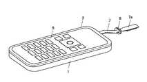
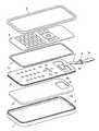
図1から図7は本発明を適用した電子機器の実施形態1の構成として折り畳み式携帯電話の操作部筐体を示したもので、1は下ケース、2は上ケース、3は中ケース、4はメイン回路基板、5はキー基板、6はパッキン、7は配線部、8はパッキン、9はキートップ、Tは両面接着テープである。DESCRIPTION OF EMBODIMENTS Hereinafter, embodiments for carrying out the present invention will be described in detail with reference to the drawings.
(Embodiment 1)
1 to 7 show an operation unit housing of a folding mobile phone as a configuration of
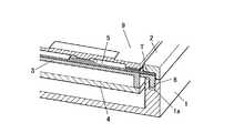
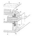
図示しない表示部筐体とヒンジ部で結合される操作部筐体は、図示例では、下ケース1、上ケース2及び中ケース3から構成されている。メイン回路基板4は下ケース1と中ケース3の間に配置され、キー基板5は中ケース3の上に載置されている。 In the illustrated example, the operation unit casing coupled to the display unit casing and the hinge unit (not shown) includes a
キー基板5は、フレキシブル基板により形成されていて、その全周囲の下面に防水部材であるパッキン6がインサート成形等により一体成形されている。パッキン6は、下ケース1の全周囲上面に形成したパッキン溝1aに嵌合されている。 The
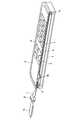
また、キー基板5には、その長手方向の一端部から延出する配線部7が一体に備えられている。この配線部7は、先端にコネクタ部7aを有するとともに、中間部に組み付けたパッキン8を有している。なお、コネクタ部7aは、操作部筐体に結合される図示しないヒンジ部内を通して表示部筐体内の表示機器にコネクタ接続され、パッキン8は、表示部筐体端部のケース間に嵌合される。 In addition, the
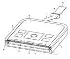
そして、キー基板5の配線部7側の端部には、開口部5aが形成されるとともに、この開口部5a内に位置するコネクタ部5bが形成されている。このコネクタ部5bは、図3から図5に示すように、中ケース3に形成した開口部3aを通して、メイン回路基板4にコネクタ接続される。 An opening 5a is formed at the end of the
以上のキー基板5の上にシート状のキートップ9が全周囲を両面接着テープTで接着して重ねられている。そして、キートップ9を囲む上ケース2を、下ケース1のパッキン溝1aの周囲上と、そのパッキン溝1aにパッキン6を嵌合したキー基板5の全周囲上に重ねて、下ケース1及び上ケース2を互いにネジ固定(図省略)により合体する。 A sheet-
以上において、図3、図4、図6及び図7に示すように、キー基板5上のメタルドームスイッチの上に、キートップ9のプッシュキーがそれぞれ位置した状態となる。 In the above, as shown in FIGS. 3, 4, 6, and 7, the push key of the
以上、実施形態の防水筐体構造を備える携帯電話によれば、フレキシブル基板によるキー基板5の全周囲の下面に一体成形して備えたパッキン6を、下ケース1のパッキン溝1aに嵌合して、キー基板5上のキートップ9を囲む上ケース2を、下ケース1のパッキン溝1aの周囲上と、そのパッキン溝1aにパッキン6を嵌合したキー基板5の全周囲上に重ねたことで、下ケース1及び上ケース2間の防水と、キー基板5の端部から引き出される配線部7の防水とを、簡単な構成で容易に実現できる。 As described above, according to the mobile phone having the waterproof casing structure of the embodiment, the
そして、キー基板5上にキートップ9の全周囲を両面接着テープTで貼り付けることで、下ケース1の内部、キー基板5のコネクタ部5bによるメイン回路基板4へのコネクタ接続部、キー基板5上のメタルドームスイッチとキートップ9のプッシュキーとのキー接点部の防水を容易に実現できる。 Then, by sticking the entire periphery of the
(実施形態2)
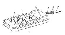
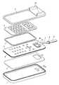
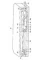
図8から図10は実施形態2としてスライド式携帯電話の操作部筐体を示したもので、前述した実施形態1と同様に、1は下ケース、2は上ケース、3は中ケース、4はメイン回路基板、5はキー基板、6はパッキン、7は配線部、8はパッキン、9はキートップ、Tは両面接着テープである。(Embodiment 2)
FIGS. 8 to 10 show the operation unit housing of the slide type mobile phone as the second embodiment. As in the first embodiment, 1 is a lower case, 2 is an upper case, 3 is a middle case, Is a main circuit board, 5 is a key board, 6 is packing, 7 is a wiring portion, 8 is packing, 9 is a key top, and T is a double-sided adhesive tape.
すなわち、実施形態2は、前述した実施形態1と同様の防水筐体構造であって、図示のように、上ケース2の長手方向の一端部側にスライドレール2aを備えたもので、このスライドレール2aに図示しない表示部筐体がスライド操作可能に組み付けられる。なお、キートップ9及び両面接着テープTは、スライドレール2aを備えた上ケース2の開口部に対応した大きさの形状となっている。 That is, the second embodiment has a waterproof casing structure similar to that of the first embodiment described above, and includes a
以上において、キー基板5には、中ケース3の開口部3aに対応する部分の下面にコネクタ部5cが備えられており、メイン回路基板4には、中ケース3の開口部3aの近傍に対応する部分の上面にコネクタ部4aが備えられている。以上、キー基板5下のコネクタ部5cとメイン回路基板4上のコネクタ部4aとを、中ケース3の開口部3aに通されたフレキシブル基板などの中継ケーブル11でコネクタ接続している。 As described above, the
そして、下ケース1には、通気孔1hを形成して、その通気孔1hの内側に防水通気膜12を接着している。また、中ケース3とキー基板5には、図示例では、同一位置の通気孔3h・5hをそれぞれ形成している。 The
以上、実施形態2の防水筐体構造によれば、前述した実施形態1の防水筐体構造と同様の作用効果が得られることに加えて、操作部筐体の完全密閉構造において、中ケース3及びキー基板5の通気孔3h・5hと、下ケース1の防水通気膜12とによって、筐体内外の圧力調整を実現できる。 As described above, according to the waterproof housing structure of the second embodiment, in addition to obtaining the same operational effects as the waterproof housing structure of the first embodiment described above, in the completely sealed structure of the operation unit housing, the
なお、中継ケーブル11を用いずに、メイン回路基板4に対しキー基板5を、中ケース3の開口部3aにおいて、バネ接点などで直接接続をとっても良い。 Instead of using the
(実施形態3)
図11から図14は実施形態3としてスライド式携帯電話の操作部筐体を示したもので、前述した実施形態2と同様に、1は下ケース、2は上ケース、2aはスライドレール、3は中ケース、4はメイン回路基板、5はキー基板、6はパッキン、7は配線部、8はパッキン、9はキートップ、Tは両面接着テープである。(Embodiment 3)
FIGS. 11 to 14 show an operation unit housing of a slide type mobile phone as a third embodiment. As in the second embodiment, 1 is a lower case, 2 is an upper case, 2a is a slide rail, Is a middle case, 4 is a main circuit board, 5 is a key board, 6 is packing, 7 is a wiring portion, 8 is packing, 9 is a key top, and T is a double-sided adhesive tape.
すなわち、実施形態3は、前述した実施形態2と同様の防水筐体構造であって、図示のように、キー基板5のコネクタ部5bの周囲の前記開口部5aをラバー13により封止密閉したものである。このラバー13は、図4に示したように、伸縮しやすい断面波形形状で、インサート成形等でキー基板5に一体成形されている。 That is, the third embodiment has the same waterproof housing structure as the second embodiment described above, and the
そして、キー基板5のコネクタ部5bとメイン回路基板4上のコネクタ部4aとを、中ケース3の開口部3aにおいて、直接コネクタ接続している。 The
以上、実施形態3の防水筐体構造によれば、前述した実施形態1の防水筐体構造と同様の作用効果が得られることに加えて、キー基板5のコネクタ部5bとメイン回路基板4上のコネクタ部4aとを、中ケース3の開口部3aにおいて、直接コネクタ接続する構造としながら、キー基板5のコネクタ部5bの周囲の前記開口部5aをラバー13により封止密閉する構造として防水できる。 As described above, according to the waterproof housing structure of the third embodiment, in addition to the same effects as the waterproof housing structure of the first embodiment described above, the
(実施形態4)
図15から図17は実施形態4として折り畳み式携帯電話の操作部筐体を示したもので、21は下ケース、22は上ケース、23は操作キー、24はメイン回路基板、26はパッキン、27は配線部、28は防水コネクタである。(Embodiment 4)
FIGS. 15 to 17 show an operation unit housing of a foldable mobile phone as a fourth embodiment, in which 21 is a lower case, 22 is an upper case, 23 is an operation key, 24 is a main circuit board, 26 is a packing, 27 is a wiring part and 28 is a waterproof connector.
図示しない表示部筐体とヒンジ部で結合される操作部筐体は、図示例では、下ケース21及び上ケース22から構成されている。メイン回路基板24は、下ケース21と上ケース22の間に配置されていて、その全周囲に防水部材であるパッキン26がインサート成形等により一体成形されている。パッキン26は、下ケース21及び上ケース22の全周囲に形成したパッキン溝21a・22aに嵌合されている。 In the illustrated example, the operation unit casing coupled with the display unit casing and the hinge unit (not shown) includes a
メイン回路基板24の長手方向一端には、パッキン26から外側に突出するコネクタ部24aが一体に形成され、このコネクタ部24aは、パッキン26と一体に形成したコネクタ防水部26aにより各端子が囲まれている。このコネクタ部24aには、別体のフレキシブル基板による配線部27が一端のコネクタ部27aで接続される。配線部27は、他端にもコネクタ部27bを備えている。 A
また、メイン回路基板24の長辺部の一方には、防水コネクタ28が搭載されており、この防水コネクタ28はパッキン26を貫通して外側に突出している。この防水コネクタ28も、メイン回路基板24の全周囲へのパッキン26とともにインサート成形等により一体に成形される。 A
以上、実施形態4の防水筐体構造を備える携帯電話によれば、メイン回路基板24の全周囲に一体成形して備えたパッキン26を、下ケース21及び上ケース22のパッキン溝21a・22aに嵌合したことで、下ケース21及び上ケース22間の防水と、メイン回路基板24からコネクタ接続して引き出される配線部27の防水とを、簡単な構成で容易に実現できる。 As described above, according to the mobile phone having the waterproof casing structure of the fourth embodiment, the packing 26 integrally formed around the
そして、メイン回路基板24を、その全周囲のパッキン26を介して下ケース21及び上ケース22間に挟みこんだことで、基板エリアをギリギリまで増やせるメリットが得られるとともに、パッキン26を介してメイン回路基板24が保持されるために、緩衝効果も期待できる。 And, by sandwiching the
さらに、パッキン26を貫通した防水コネクタ28としたため、端子部から内部への防水が図れる防水コネクタ28の周囲の防水性も確実なものである。また、その他、応用例としてサイドキーや充電端子などの部品を、メイン回路基板24と一緒にその全周囲のパッキン26と一体成形すれば、防水箇所を減らしたり、省スペース化することも可能になる。 Further, since the
図18及び図19はコネクタ部のバネ端子部分を示したもので、図示のように、メイン回路基板24のパッキン26から外側に突出するコネクタ部24aの各端子をバネ端子24bとして、下ケース21及び上ケース22にコネクタ部24a及びコネクタ防水部26aを覆う延長部21b・22bを一体に形成したものである。 18 and 19 show the spring terminal portion of the connector portion. As shown in the drawing, each terminal of the
以上において、下ケース21及び上ケース22の延長部21b・22b間のスリットに、配線部27のコネクタ部27aを挿入して、そのコネクタ部27aを、メイン回路基板24のコネクタ部24aのバネ端子24bに接続する。このとき、下ケース21及び上ケース22の延長部21b・22bのリブによって、パッキン26と一体のコネクタ防水部26aが圧縮されている。 In the above, the
従って、メイン回路基板24のパッキン26から外側に突出するコネクタ部24aのバネ端子24bに対し配線部27のコネクタ部27aを接続した状態において、パッキン26と一体のコネクタ防水部26aの圧縮による防水を行うことができる。 Therefore, in a state where the
(実施形態5)
図20から図22は実施形態5として折り畳み式携帯電話の操作部筐体を示したもので、前述した実施形態4と同様に、21は下ケース、21aはパッキン溝、22は上ケース、22aはパッキン溝、23は操作キー、24はメイン回路基板、26はパッキン、27は配線部、27bはコネクタ部である。(Embodiment 5)
20 to 22 show the operation unit housing of the folding cellular phone as the fifth embodiment. As in the fourth embodiment, 21 is a lower case, 21a is a packing groove, 22 is an upper case, 22a. Is a packing groove, 23 is an operation key, 24 is a main circuit board, 26 is a packing, 27 is a wiring portion, and 27b is a connector portion.
すなわち、実施形態5は、前述した実施形態4と同様の防水筐体構造であって、図示のように、メイン回路基板24のパッキン26から外側に突出するコネクタ部24cの各端子を露出させるコネクタ防水部26cとして、配線部27のコネクタ部27cを覆う防水キャップ29を設けて、下ケース21及び上ケース22に防水キャップ29を覆う延長部21b・22bを一体に形成したものである。 That is, the fifth embodiment has a waterproof housing structure similar to that of the fourth embodiment described above, and as shown in the figure, a connector that exposes each terminal of the
以上において、下ケース21及び上ケース22の延長部21b・22b間の挿入孔に、配線部27のコネクタ部27cを覆う防水キャップ29を密着挿入して、そのコネクタ部27cを、メイン回路基板24のコネクタ部24cに接続する。このとき、コネクタ部24cの各端子を露出させるコネクタ防水部26cが防水キャップ29の内周に密着されている。 In the above, the
以上、実施形態5の防水筐体構造によれば、前述した実施形態4の防水筐体構造と同様の作用効果が得られることに加えて、メイン回路基板24のパッキン26から外側に突出するコネクタ部24cに対し配線部27のコネクタ部27cを接続した状態において、パッキン26と一体のコネクタ防水部26cの防水キャップ29の内周に対する密着による防水を行うことができる。 As described above, according to the waterproof housing structure of the fifth embodiment, in addition to obtaining the same operational effects as the waterproof housing structure of the fourth embodiment described above, a connector that protrudes outward from the packing 26 of the
なお、以上の防水コネクタ構造は、表示部との接続端子だけでなく外部接続の通信、イヤホン端子等にも適用できる。 The above waterproof connector structure can be applied not only to the connection terminal with the display unit but also to external connection communication, an earphone terminal, and the like.
(実施形態6)
図23及び図24は実施形態6として折り畳み式携帯電話の表示部筐体を示したもので、31は下ケース、32は上ケース、33は表示装置、34は表示部基板、36はパッキン、37は配線部、38はパッキンである。(Embodiment 6)
FIG. 23 and FIG. 24 show a display unit housing of a foldable mobile phone as
図示しない操作部筐体とヒンジ部で結合される表示部筐体は、図示例では、下ケース31及び上ケース32から構成されている。表示部基板34は、下ケース31と上ケース32の間に配置されていて、その全周囲に防水部材であるパッキン36がインサート成形等により一体成形されている。パッキン36は、下ケース31及び上ケース32の全周囲のパッキン溝31a・32a間に挟持される。 In the illustrated example, the display unit casing coupled to the operation unit casing and the hinge unit (not shown) includes a
表示部基板34上には、上ケース32の表示窓32aに表示画面が位置する液晶等の表示装置33が搭載されており、この表示装置33にコネクタ接続したフレキシブル基板による配線部37は、パッキン36にインサート成形等により一体成形されている。さらに、この配線部37には、操作部筐体端部のケース間に嵌合されるパッキン38が備えられている。このパッキン38も、図示しないヒンジ部内を通して操作部筐体内のメイン回路基板にコネクタ接続される配線部37とともにインサート成形等により一体に成形される。 On the
以上、実施形態6の防水筐体構造を備える携帯電話によれば、表示部基板34の全周囲に一体成形して備えたパッキン36を、下ケース31及び上ケース32のパッキン溝31a・32a間に挟持したことで、下ケース31及び上ケース32間の防水と、表示部基板34からコネクタ接続して引き出される配線部37の防水とを、簡単な構成で容易に実現できる。 As described above, according to the mobile phone having the waterproof housing structure of the sixth embodiment, the packing 36 integrally formed around the entire periphery of the
(実施形態7)
図25は実施形態7として折り畳み式携帯電話の操作部筐体を示したもので、41は下ケース、42は上ケース、43は回路基板、44はフレキシブル基板、45はパッキン、46は防水シート、47はパッキン、48はパッキン固定枠、49は電池である。(Embodiment 7)
FIG. 25 shows an operation unit housing of a foldable mobile phone as
すなわち、実施形態7は、図示しない表示部筐体とヒンジ部で結合される操作部筐体に適用したもので、操作部筐体は、図示例では、下ケース41及び上ケース42から構成されている。回路基板43は、上ケース42内に配置され、フレキシブル基板44は、下ケース41及び上ケース42間に配置されている。 That is, the seventh embodiment is applied to an operation unit case that is coupled to a display unit case and a hinge unit (not shown), and the operation unit case includes a
フレキシブル基板44は、例えば、非接触データ通信を行うためのフェリカアンテナなどの各種アンテナなどの回路形成も可能で、その全周囲の上面に防水部材であるパッキン45がインサート成形等により一体成形されている。パッキン45は、上ケース42の全周囲の下面に形成したパッキン溝421に嵌合されている。 The
また、フレキシブル基板44には、その長手方向の一端部から延出する外部配線部441が一体に備えられている。この外部配線部441は、下ケース41及び上ケース42間から外部に引き出されて、先端にコネクタ部を有するとともに、中間部に図示しないパッキンを有している。なお、コネクタ部は、操作部筐体に結合される図示しないヒンジ部内を通して表示部筐体内の表示機器にコネクタ接続され、パッキンは、表示部筐体端部のケース間に嵌合される。 The
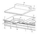
そして、フレキシブル基板44の外部配線部441側の端部には、第一の開口部445が形成されるとともに、この第一の開口部445から引き出される内部配線部446が形成されている。この内部配線部446は、先端にコネクタ部447を有している。このコネクタ部447は、図示のように、回路基板43にコネクタ接続される。また、切り抜き部445の周囲下面に防水シート46が接着されている。 A
さらに、フレキシブル基板44の他半部には、大きな第二の開口部449が形成されており、この第二の開口部449の周囲上面に防水部材であるパッキン47がインサート成形等により一体成形されている。このパッキン47は、外周にパッキン固定枠48を一体成形したもので、回路基板43に密着状態とされている。ここで、パッキン固定枠48は一体成形でなく別体でも良く、パッキン47の受けになっていれば良い。さらに、パッキン固定枠48は回路基板43に密着していなくても良い。 Furthermore, a large
なお、第二の開口部449内には、電池49が収納されている。この電池49は、下ケース41の一半部に形成された電池着脱用開口部411に合わさる電池蓋491を一体に有している。 A
以上、実施形態7の防水筐体構造によれば、フレキシブル基板44の全周囲上面に一体成形して備えたパッキン45を、上ケース42のパッキン溝421に嵌合して、上ケース42のパッキン溝421の周囲下に下ケース41を重ねたことで、下ケース41及び上ケース42間の防水と、フレキシブル基板44から引き出される配線部441の防水とを、簡単な構成で容易に実現できる。 As described above, according to the waterproof housing structure of the seventh embodiment, the packing 45 integrally formed on the entire upper surface of the
そして、フレキシブル基板44の第一の開口部445の周囲下面に防水シート46を接着したことで、内部配線部446を引き出す第一の開口部445に対する防水を容易に実現できる。 The
さらに、フレキシブル基板44の第二の開口部449の周囲上面に設けたパッキン47にて、電池49の収納部の防水を容易に実現できる。 Furthermore, waterproofing of the storage part of the
また、実施形態7では、フェリカアンテナなどの各種アンテナをフレキシブル基板44に回路形成すれば、回路基板43や金属部から離せるので、アンテナの感度を上げながら配置効率をより高めることができる。 In the seventh embodiment, if various antennas such as a Felica antenna are formed on the
なお、防水シートの接着は接着剤でも両面接着テープでも良い。
また、防水シートは、フレキシブル基板とパッキンの一体成形時にラバーで開口部を覆ってしまうようにしても良い。The waterproof sheet may be bonded with an adhesive or a double-sided adhesive tape.
Moreover, you may make it a waterproof sheet cover an opening part with a rubber | gum at the time of integral molding of a flexible substrate and packing.
(実施形態8)
図26から図27は実施形態8として折り畳み式携帯電話を示したもので、51は操作部筐体、52は表示部筐体、53はヒンジ部、54は操作部、55は表示部、56は下ケース、57は上ケース、58はフレキシブル基板、59はパッキンである。(Embodiment 8)
26 to 27 show a foldable mobile phone as an eighth embodiment, in which 51 is an operation unit casing, 52 is a display unit casing, 53 is a hinge unit, 54 is an operation unit, 55 is a display unit, 56 Is a lower case, 57 is an upper case, 58 is a flexible substrate, and 59 is a packing.
すなわち、実施形態8は、表示部筐体52とヒンジ部53で結合される操作部筐体51に適用したもので、操作部筐体51は、図示例では、下ケース56及び上ケース57から構成されている。フレキシブル基板58は、下ケース56及び上ケース57間に配置されている。 In other words, the eighth embodiment is applied to the
フレキシブル基板58は、例えば、非接触データ通信を行うためのフェリカアンテナなどの各種アンテナなど回路形成も可能で、その全周囲を挟んで上下に突出する防水部材であるパッキン59がインサート成形等により一体成形されている。パッキン59は、下ケース56の全周囲の上面に形成したパッキン溝561に嵌合されるとともに、上ケース57の全周囲の下面に形成したパッキン溝571に嵌合されている。以上のパッキン溝561・571の外側において、下ケース56及び上ケース57が四隅部にネジnを締め込んで合体される。 The
また、フレキシブル基板58には、その長手方向の一端部から延出する外部配線部581が一体に備えられている。この外部配線部581は、下ケース56及び上ケース57間から外部に引き出されて、先端にコネクタ部582を有するとともに、中間部に図示しないパッキンを有している。なお、コネクタ部582は、操作部筐体51に結合されるヒンジ部53内を通して表示部筐体52内の表示機器にコネクタ接続され、パッキンは、表示部筐体52端部のケース間に嵌合される。 In addition, the
そして、フレキシブル基板58には、パッキン59の内周近傍に沿って大開口部585が形成されるとともに、この大開口部585の外部配線部581側の端部から引き出される内部配線部586が形成されている。この内部配線部586は、先端にコネクタ部587を有している。このコネクタ部587は、図示しない回路基板にコネクタ接続される。 The
以上、実施形態8の防水筐体構造によれば、フレキシブル基板58の全周囲を挟んで一体成形して備えたパッキン59を、下ケース56及び上ケース57のパッキン溝561・571に嵌合したことで、下ケース56及び上ケース57間の防水と、フレキシブル基板58から引き出される配線部581の防水とを、簡単な構成で容易に実現できる。 As described above, according to the waterproof housing structure of the eighth embodiment, the packing 59 provided integrally with the entire periphery of the
また、フェリカアンテナなどの各種アンテナをフレキシブル基板58に回路形成すれば、回路基板や金属部から離せるので、アンテナの感度を上げながら配置効率をより高めることができる。 In addition, if various antennas such as a Felica antenna are formed on the
(変形例)
なお、以上の実施形態においては、携帯電話としたが、本発明はこれに限定されるものではなく、カメラ、PDA、ノートパソコン、ウェアラブルパソコン、電卓、電子辞書など、複数のケースを組み立てて筐体の防水を図る携帯型電子機器を含む電子機器すべてに用いることができる。
また、実施形態では、操作部の入力形式を押しボタン式としたが、タッチパネルであっても良い。
さらに、ケース、基板、防水部材、配線部の形状等も任意であり、その他、具体的な細部構造等についても適宜に変更可能であることは勿論である。(Modification)
In the above embodiment, the cellular phone is used. However, the present invention is not limited to this, and a plurality of cases such as a camera, a PDA, a notebook computer, a wearable computer, a calculator, and an electronic dictionary are assembled to form a housing. It can be used for all electronic devices including portable electronic devices that are waterproof.
In the embodiment, the input format of the operation unit is a push button type, but a touch panel may be used.
Furthermore, the shape of the case, the substrate, the waterproof member, the wiring portion, and the like are arbitrary, and it is needless to say that other specific detailed structures can be appropriately changed.
(付記1)
第一のケースと、
この第一のケースと組み合わせられる第二のケースと、
これら第一及び第二の両ケース間の全周にわたって挟持される防水部材と、
この防水部材が全周にわたって一体的に設けられた電子基板部と、
この電子基板部の端部から引き出された配線部と、を備えることを特徴とする防水筐体構造。(Appendix 1)
The first case,
A second case combined with this first case;
A waterproof member sandwiched over the entire circumference between the first and second cases;
An electronic board part in which this waterproof member is integrally provided over the entire circumference;
A waterproof housing structure comprising: a wiring portion drawn out from an end portion of the electronic substrate portion.
(付記2)
前記防水部材は、前記電子基板部に対し一面側に設けられていて、
前記配線部は、前記電子基板部の端部から一体に形成されていることを特徴とする付記1に記載の防水筐体構造。(Appendix 2)
The waterproof member is provided on one surface side with respect to the electronic substrate part,
The waterproof housing structure according to
(付記3)
前記電子基板部は、回路基板と、この回路基板にコネクタ接続されるキー基板とからなり、
前記配線部は、前記キー基板に設けられていることを特徴とする付記1または2に記載の防水筐体構造。(Appendix 3)
The electronic board part is composed of a circuit board and a key board connected to the circuit board by a connector,
The waterproof housing structure according to
(付記4)
前記キー基板の内部に引き出し可能なコネクタ部が形成されることを特徴とする付記3に記載の防水筐体構造。(Appendix 4)
The waterproof casing structure according to
(付記5)
前記キー基板に形成した、前記コネクタ部が引き出される開口部は、弾性部材で埋めて防水されていることを特徴とする付記4に記載の防水筐体構造。(Appendix 5)
The waterproof housing structure according to
(付記6)
前記防水部材は、前記電子基板部の全周を挟んで設けられていて、
前記配線部は、前記電子基板部の前記防水部材から突出した端部に接続されることを特徴とする付記1に記載の防水筐体構造。(Appendix 6)
The waterproof member is provided across the entire circumference of the electronic substrate part,
The waterproof housing structure according to
(付記7)
前記電子基板部は、回路基板であることを特徴とする付記6に記載の防水筐体構造。(Appendix 7)
The waterproof housing structure according to
(付記8)
前記回路基板には、前記防水部材を貫通する防水コネクタが搭載されていることを特徴とする付記7に記載の防水筐体構造。(Appendix 8)
The waterproof housing structure according to
(付記9)
前記電子基板部には第二の開口部が形成され、
この第二の開口部の周囲に第二の防水部材を備えることを特徴とする付記4に記載の防水筐体構造。(Appendix 9)
A second opening is formed in the electronic substrate part,
The waterproof housing structure according to
(付記10)
前記キー基板に形成した、前記コネクタ部が引き出される開口部は、前記防水部材の内周近傍まで形成されていることを特徴とする付記4に記載の防水筐体構造。(Appendix 10)
The waterproof housing structure according to
(付記11)
付記1から10のいずれか一つに記載の防水筐体構造を備えることを特徴とする電子機器。(Appendix 11)
An electronic apparatus comprising the waterproof housing structure according to any one of
1 第一のケース
1a パッキン溝
2 第二のケース
3 中ケース
3a 開口部
4 回路基板
5 キー基板
5a 開口部
5b コネクタ部
6 防水部材
7 配線部
7a コネクタ部
8 防水部材
9 キートップ
11 中継ケーブル
12 防水通気膜
13 弾性部材
21 第一のケース
21a パッキン溝
21b 延長部
22 第二のケース
22a パッキン溝
22b 延長部
23 操作キー
24 回路基板
24a コネクタ部
24b バネ端子
24c コネクタ部
26 防水部材
26a コネクタ防水部
26c コネクタ防水部
27 配線部
27a コネクタ部
27b コネクタ部
27c コネクタ部
28 防水コネクタ
29 防水キャップ
31 第一のケース
32 第二のケース
33 表示装置
34 回路基板
36 防水部材
37 配線部
38 防水部材
41 第一のケース
411 開口部
42 第二のケース
421 パッキン溝
43 回路基板
44 フレキシブル基板
441 配線部
445 開口部
446 配線部
447 コネクタ部
449 開口部
45 防水部材
46 防水シート
47 防水部材
48 固定枠
49 電池
56 第一のケース
561 パッキン溝
57 第二のケース
571 パッキン溝
58 フレキシブル基板
581 配線部
582 コネクタ部
585 切り抜き部
586 配線部
587 コネクタ部
59 防水部材DESCRIPTION OF
Claims (4)
Translated fromJapanese前記第一のケースと組み合わせられる第二のケースと、
前記第一のケースと前記第二のケースとの間に収納される電子基板部と、
前記電子基板部の側面から引き出された配線部と、
前記電子基板部の第一のケース側の面に全周にわたって一体的に設けられた第一の防水部材と、
前記第一のケースと前記電子基板部との間に設けられ、第二のケース側の面と前記電子基板部との間に前記第一の防水部材を全周にわたって挟む回路基板部と、を備え、
前記電子基板部と前記配線部との接続部分は、第一のケース側の面が段差のない平坦面に形成されていることを特徴とする防水筐体構造。The first case,
A second case combined with the first case;
An electronic board portion housed between the first case and the second case;
A wiring portion drawn from the side surface of the electronic substrate portion;
A first waterproofing member integrally provided over the entire circumference on the surface of the first case side of the electronic substrate part;
A circuit board part provided between the first case and the electronic board part, and sandwiching the first waterproof member over the entire circumference between the surface of the second case and the electronic board part; Prepared,
The connecting part between the electronic substrate part and the wiring part is formed with a flat surface having no step on the surface on the first case side.
前記第二のケースと前記電子基板部との間に設けられ、第一のケース側の面と前記電子基板部との間に前記第二の防水部材を全周にわたって挟むキートップ部と、を備え、
前記電子基板部と前記配線部との接続部分は、第二のケース側の面が段差のない平坦面に形成されていることを特徴とする請求項1に記載の防水筐体構造。A second waterproof member integrally provided on the entire surface of the second case side of the electronic substrate portion;
A key top portion provided between the second case and the electronic substrate portion, and sandwiching the second waterproof member over the entire circumference between the surface of the first case and the electronic substrate portion; Prepared,
2. The waterproof housing structure according to claim 1, wherein a surface of the second case side of the connecting portion between the electronic board portion and the wiring portion is formed on a flat surface having no step.
前記電子基板部は、前記コネクタ部を介して、前記第一の防水部材に囲まれた領域内において前記回路基板部と接続されていることを特徴とする請求項2に記載の防水筐体構造。The electronic board part is formed with a connector part drawn from a part surrounded by the second waterproof member,
The waterproof case structure according to claim 2, wherein the electronic board part is connected to the circuit board part in the region surrounded by the first waterproof member via the connector part. .
Priority Applications (1)
| Application Number | Priority Date | Filing Date | Title |
|---|---|---|---|
| JP2013119073AJP2013179355A (en) | 2013-06-05 | 2013-06-05 | Waterproof housing structure and electronic apparatus |
Applications Claiming Priority (1)
| Application Number | Priority Date | Filing Date | Title |
|---|---|---|---|
| JP2013119073AJP2013179355A (en) | 2013-06-05 | 2013-06-05 | Waterproof housing structure and electronic apparatus |
Related Parent Applications (1)
| Application Number | Title | Priority Date | Filing Date |
|---|---|---|---|
| JP2008029216ADivisionJP5354639B2 (en) | 2008-02-08 | 2008-02-08 | Waterproof housing structure and electronic device |
Publications (1)
| Publication Number | Publication Date |
|---|---|
| JP2013179355Atrue JP2013179355A (en) | 2013-09-09 |
Family
ID=49270652
Family Applications (1)
| Application Number | Title | Priority Date | Filing Date |
|---|---|---|---|
| JP2013119073APendingJP2013179355A (en) | 2013-06-05 | 2013-06-05 | Waterproof housing structure and electronic apparatus |
Country Status (1)
| Country | Link |
|---|---|
| JP (1) | JP2013179355A (en) |
Cited By (6)
| Publication number | Priority date | Publication date | Assignee | Title |
|---|---|---|---|---|
| JP2016530626A (en)* | 2014-07-18 | 2016-09-29 | 小米科技有限責任公司Xiaomi Inc. | Wearable device and manufacturing method thereof |
| JP2017033514A (en)* | 2015-07-29 | 2017-02-09 | 豊美 柳生 | Five point crime prevention buzzer |
| US9615791B2 (en) | 2014-07-18 | 2017-04-11 | Xiaomi Inc. | Wearable device and method for manufacturing the same |
| GB2543649A (en)* | 2015-10-19 | 2017-04-26 | Motorola Solutions Inc | Sealing system and method for sealing of electronics housings |
| JP2019212696A (en)* | 2018-05-31 | 2019-12-12 | 株式会社東芝 | Electronic apparatus |
| CN112201937A (en)* | 2020-09-30 | 2021-01-08 | 西安易朴通讯技术有限公司 | Manufacturing method of antenna assembly, antenna assembly and electronic equipment |
Citations (1)
| Publication number | Priority date | Publication date | Assignee | Title |
|---|---|---|---|---|
| JP2009187893A (en)* | 2008-02-08 | 2009-08-20 | Casio Hitachi Mobile Communications Co Ltd | Waterproof housing structure and electronic equipment |
- 2013
- 2013-06-05JPJP2013119073Apatent/JP2013179355A/enactivePending
Patent Citations (1)
| Publication number | Priority date | Publication date | Assignee | Title |
|---|---|---|---|---|
| JP2009187893A (en)* | 2008-02-08 | 2009-08-20 | Casio Hitachi Mobile Communications Co Ltd | Waterproof housing structure and electronic equipment |
Cited By (12)
| Publication number | Priority date | Publication date | Assignee | Title |
|---|---|---|---|---|
| JP2016530626A (en)* | 2014-07-18 | 2016-09-29 | 小米科技有限責任公司Xiaomi Inc. | Wearable device and manufacturing method thereof |
| US9615791B2 (en) | 2014-07-18 | 2017-04-11 | Xiaomi Inc. | Wearable device and method for manufacturing the same |
| JP2017033514A (en)* | 2015-07-29 | 2017-02-09 | 豊美 柳生 | Five point crime prevention buzzer |
| GB2543649A (en)* | 2015-10-19 | 2017-04-26 | Motorola Solutions Inc | Sealing system and method for sealing of electronics housings |
| CN106852054A (en)* | 2015-10-19 | 2017-06-13 | 摩托罗拉解决方案公司 | For the sealing system and method for sealing electronic device shell |
| US9775256B2 (en) | 2015-10-19 | 2017-09-26 | Motorola Solutions, Inc. | Sealing system and method for sealing of electronics housings |
| GB2543649B (en)* | 2015-10-19 | 2018-05-30 | Motorola Solutions Inc | Sealing system and method for sealing of electronics housings |
| CN106852054B (en)* | 2015-10-19 | 2019-08-16 | 摩托罗拉解决方案公司 | Sealing system and method for sealing electronic device shell |
| JP2019212696A (en)* | 2018-05-31 | 2019-12-12 | 株式会社東芝 | Electronic apparatus |
| JP7077147B2 (en) | 2018-05-31 | 2022-05-30 | 株式会社東芝 | Electronics |
| CN112201937A (en)* | 2020-09-30 | 2021-01-08 | 西安易朴通讯技术有限公司 | Manufacturing method of antenna assembly, antenna assembly and electronic equipment |
| CN112201937B (en)* | 2020-09-30 | 2023-02-28 | 西安易朴通讯技术有限公司 | Manufacturing method of antenna assembly, antenna assembly and electronic equipment |
Similar Documents
| Publication | Publication Date | Title |
|---|---|---|
| JP5354639B2 (en) | Waterproof housing structure and electronic device | |
| US7957123B2 (en) | Portable electronic device | |
| US7561684B2 (en) | Mounting structure for an electroacoustic transducer | |
| JP2013179355A (en) | Waterproof housing structure and electronic apparatus | |
| US20120063077A1 (en) | Handheld terminal device and electronic equipment | |
| CN106128827B (en) | Side key structure and mobile terminal | |
| WO2019052332A1 (en) | Display screen assembly and mobile terminal | |
| WO2009098844A1 (en) | Portable terminal device | |
| JP4258295B2 (en) | Foldable mobile terminal | |
| EP4287796A1 (en) | Electronic device comprising sealing member | |
| CN110071003A (en) | The water-tight device and electronic equipment of a kind of electronic equipment key | |
| JP5558012B2 (en) | Electronics | |
| JP2014192560A (en) | Portable terminal and assembly method of the same | |
| JP5686613B2 (en) | Electronics | |
| JP2013115615A (en) | Electronic apparatus | |
| JP4624329B2 (en) | Waterproof structure of electronic equipment | |
| JP2009043819A (en) | Electronics | |
| WO2014097654A1 (en) | Electronic apparatus | |
| JP5061369B2 (en) | Waterproof housing structure and electronic device | |
| JP5298821B2 (en) | Electronic device casing packing and case structure, and electronic device | |
| JP2011114710A (en) | Portable electronic apparatus | |
| US20120273244A1 (en) | Electronic device | |
| JP4935692B2 (en) | Mobile terminal device | |
| US20120111713A1 (en) | Portable electronic device and printed circuit board module | |
| CN206149254U (en) | Case assembly of mobile terminal and mobile terminal |
Legal Events
| Date | Code | Title | Description |
|---|---|---|---|
| A621 | Written request for application examination | Free format text:JAPANESE INTERMEDIATE CODE: A621 Effective date:20130605 | |
| A131 | Notification of reasons for refusal | Free format text:JAPANESE INTERMEDIATE CODE: A131 Effective date:20140408 | |
| A02 | Decision of refusal | Free format text:JAPANESE INTERMEDIATE CODE: A02 Effective date:20140819 |