JP2013177125A - Fixture of on-vehicle device - Google Patents
Fixture of on-vehicle deviceDownload PDFInfo
- Publication number
- JP2013177125A JP2013177125AJP2013070844AJP2013070844AJP2013177125AJP 2013177125 AJP2013177125 AJP 2013177125AJP 2013070844 AJP2013070844 AJP 2013070844AJP 2013070844 AJP2013070844 AJP 2013070844AJP 2013177125 AJP2013177125 AJP 2013177125A
- Authority
- JP
- Japan
- Prior art keywords
- vehicle device
- adhesive sheet
- vehicle
- base
- suction
- Prior art date
- Legal status (The legal status is an assumption and is not a legal conclusion. Google has not performed a legal analysis and makes no representation as to the accuracy of the status listed.)
- Granted
Links
- 239000000463materialSubstances0.000claimsabstractdescription29
- 239000000853adhesiveSubstances0.000claimsdescription57
- 230000001070adhesive effectEffects0.000claimsdescription57
- 230000007246mechanismEffects0.000claimsdescription11
- 241000252254CatostomidaeSpecies0.000abstractdescription5
- 230000008859changeEffects0.000abstractdescription5
- 238000009434installationMethods0.000abstractdescription4
- 238000001179sorption measurementMethods0.000description10
- 239000004820Pressure-sensitive adhesiveSubstances0.000description7
- PPBRXRYQALVLMV-UHFFFAOYSA-NStyreneChemical compoundC=CC1=CC=CC=C1PPBRXRYQALVLMV-UHFFFAOYSA-N0.000description6
- 230000013011matingEffects0.000description5
- 230000002093peripheral effectEffects0.000description5
- 230000009471actionEffects0.000description4
- 238000007373indentationMethods0.000description4
- 229920003002synthetic resinPolymers0.000description4
- 239000000057synthetic resinSubstances0.000description4
- 239000004698PolyethyleneSubstances0.000description3
- XUIMIQQOPSSXEZ-UHFFFAOYSA-NSiliconChemical compound[Si]XUIMIQQOPSSXEZ-UHFFFAOYSA-N0.000description3
- 238000011109contaminationMethods0.000description3
- 230000000694effectsEffects0.000description3
- 238000000034methodMethods0.000description3
- -1polyethylenePolymers0.000description3
- 229920000573polyethylenePolymers0.000description3
- 229910052710siliconInorganic materials0.000description3
- 239000010703siliconSubstances0.000description3
- 239000002390adhesive tapeSubstances0.000description2
- 238000000465mouldingMethods0.000description2
- 230000001133accelerationEffects0.000description1
- 230000008878couplingEffects0.000description1
- 238000010168coupling processMethods0.000description1
- 238000005859coupling reactionMethods0.000description1
- 238000005516engineering processMethods0.000description1
- 230000002349favourable effectEffects0.000description1
- 230000008014freezingEffects0.000description1
- 238000007710freezingMethods0.000description1
- 230000006872improvementEffects0.000description1
- 230000008018meltingEffects0.000description1
- 238000002844meltingMethods0.000description1
- 229920001187thermosetting polymerPolymers0.000description1
Images


Landscapes
- Fittings On The Vehicle Exterior For Carrying Loads, And Devices For Holding Or Mounting Articles (AREA)
- Hooks, Suction Cups, And Attachment By Adhesive Means (AREA)
Abstract
Description
Translated fromJapanese本発明は、車載装置の固定具に関するもので、より具体的には、GPS受信機などの表示パネルを有する車載装置を支持して車室内の所定位置に固定させるための車載装置の固定具の構造の改良に関する。 The present invention relates to a fixture for a vehicle-mounted device, and more specifically, a fixture for a vehicle-mounted device for supporting a vehicle-mounted device having a display panel such as a GPS receiver and fixing it to a predetermined position in a vehicle interior. It relates to the improvement of the structure.
車載装置の多くは、運転者が操作する都合からダッシュボード上に固定する配置を採ることが多い。例えばGPS受信機などの表示パネルを有する車載装置では、運転者の操作性はもちろん、視認性も良好に得るため、ダッシュボードの上面で運転の妨げにならない位置を選ぶことになる。
ダッシュボード上へ固定するには、両面粘着テープを用いて貼り付ける方法が簡単ではあるが、貼り直しが困難であること、並びに、はがした際に粘着物が残ってダッシュボードが汚れる等の問題がある。Many in-vehicle devices are often arranged on a dashboard for convenience of operation by the driver. For example, in an in-vehicle apparatus having a display panel such as a GPS receiver, not only a driver's operability but also a good visibility can be obtained. Therefore, a position that does not hinder driving is selected on the upper surface of the dashboard.
To fix it on the dashboard, it is easy to apply it with double-sided adhesive tape, but it is difficult to re-apply, and the adhesive remains when it is peeled off. There's a problem.
そこで例えば特許文献1などに見られるように、吸盤を用いて吸着により車載機器の支持,固定を行う技術の提案がある。なお、吸盤を利用した技術は比較的によく知られており、また、車載装置の固定具ではないが、特許文献2には、シャワーノズル支持具の取り付け面に吸盤を多数設ける構成としたものの提案が見られる。 Therefore, for example, as seen in Patent Document 1, there is a proposal of a technique for supporting and fixing an in-vehicle device by suction using a suction cup. In addition, the technique using a suction cup is comparatively well known, and although it is not a fixture of a vehicle-mounted apparatus,
上述した特許文献1,2のように、吸盤を利用した支持,固定の技術は比較的によく知られてはいるが、車両への適用という条件を考えると吸着力を安定に得ることは容易とは言えない。 As described in
つまり、車室内は夏期では温度が80℃程度に上昇し、冬期では氷点下に下がる場合もあって過酷であり、走行時の車両の振動も伝わる。また、特許文献1にも指摘があるように、ダッシュボードの表面はシボ加工の細かい凹凸があり、デザイン上から平面ではなく曲面に形成されている。これらの点を考慮すると、特許文献1に示すように大きな吸盤を単に1つ設ける構成をとった場合、吸盤に車両の振動が伝わり吸着部分にわずかでも空気がしみ込むと、吸着が不良になり剥がれることになる。また、曲面形成のダッシュボードの表面に対して、フィット性が良好とは言えないという欠点がある。 In other words, the temperature in the passenger compartment rises to about 80 ° C. in the summer and drops below the freezing point in the winter, and the vibration of the vehicle during travel is transmitted. Moreover, as pointed out in Patent Document 1, the surface of the dashboard has fine irregularities that are textured, and is formed in a curved surface instead of a flat surface in terms of design. In consideration of these points, when a configuration is adopted in which only one large suction cup is provided as shown in Patent Document 1, if the vibration of the vehicle is transmitted to the suction cup and even a slight amount of air infiltrates into the suction portion, the suction becomes poor and peels off. It will be. In addition, there is a drawback that the fitting property is not good with respect to the surface of the curved dashboard.
また、吸盤を一つだけ設ける構成をとった場合、必要な吸着力を得るためには吸盤の高さを高くする必要がある。またその高さを有する1つの吸盤を安定的に支えるために吸盤を外側等から支える構造が必要となり、さらに全体の高さが高くなってしまうという問題があった。特に、表示装置を備える機器の場合、表示装置の表示画面を運転者が見やすい高さに設置したいため、組み付けの高さを低くしたい場合があるが、このように一つの吸盤で支えると、機器の設置位置の高さを低く抑えることが困難であった。 Moreover, when the structure which provides only one suction cup is taken, in order to obtain a required suction | attraction force, it is necessary to make the height of a suction cup high. Further, in order to stably support one suction cup having the height, a structure for supporting the suction cup from the outside or the like is required, and there is a problem that the overall height is further increased. In particular, in the case of a device equipped with a display device, the display screen of the display device may be installed at a height that is easy for the driver to see, so the assembly height may be lowered. It was difficult to keep the height of the installation position low.
この発明は上述した課題を解決するもので、その目的は、固定具の高さを全体的に低く抑えつつ、強い吸着力を発揮することができる車載装置の固定具を提供することにある。さらに、他の目的としては、曲面形成のダッシュボードの表面であっても良好にフィットでき、車両の振動や温度変化など過酷な条件下でも吸着力を安定に得ることができ、固定を強固に行えるとともに、貼り直しも容易であり、はがした後の表面の汚損がない車載装置の固定具を提供することにある。 This invention solves the subject mentioned above, The objective is to provide the fixture of the vehicle-mounted apparatus which can exhibit strong adsorption | suction power, keeping the height of a fixture low overall. In addition, for other purposes, even a curved dashboard surface can be fitted well, and the adsorption force can be obtained stably even under harsh conditions such as vehicle vibrations and temperature changes, and the fixation is strong An object of the present invention is to provide a fixture for an in-vehicle apparatus that can be easily attached and re-attached, and has no surface contamination after peeling.
上述した目的を達成するために、本発明に係る車載装置の固定具は、(1)車載装置の基部へ着脱可能に組み付けて車内の所定位置へ固定させるものであって、車載装置の底面の取り付け部に嵌め合う板材であり当該板材の裏面に連結手段を有するジョイントベースと、連結手段の受け座を有する基台とを備えて、柔軟性を有するゲル状のシート材からなる粘着性シートを基台の底面に取り付け、粘着性シートには、放物線状などのなめらかな曲面形状のくぼみと当該くぼみを囲む環状の隆起部からなる吸盤を複数(好ましくは多数)配列させて形成する構成にする。車載装置としては各種のものがあるが、例えば表示装置(表示パネル)を有するものがある。また、車内の所定位置とは、例えば、ダッシュボードの上面などがある。もちろんの、車載装置や、その設置位置は、上記例示したものに限られるものではない。 In order to achieve the above-described object, a fixture for an in-vehicle device according to the present invention is (1) detachably assembled to the base of the in-vehicle device and fixed to a predetermined position in the vehicle. A pressure-sensitive adhesive sheet made of a flexible gel-like sheet material, comprising a joint base having a connecting means on the back surface of the plate material, and a base having a receiving seat for the connecting means. The adhesive sheet is attached to the bottom surface of the base, and the adhesive sheet is formed by arranging a plurality of (preferably many) suction cups, each of which has a concave portion having a smooth curved shape such as a parabola, and an annular raised portion surrounding the concave portion. . There are various types of in-vehicle devices, for example, there are devices having a display device (display panel). The predetermined position in the vehicle includes, for example, the upper surface of the dashboard. Of course, the in-vehicle device and its installation position are not limited to those exemplified above.
(2)車載装置の底面の取り付け部に、柔軟性を有するゲル状のシート材からなる粘着性シートを有し、粘着性シートには、放物線状などのなめらかな曲面形状のくぼみと当該くぼみを囲む環状の隆起部からなる吸盤を複数(好ましくは多数)配列させて形成する構成にすることもよい。柔軟性は、高い方が取付面に対する密着性もよくなるので好ましい。粘着性シートは、予め設けていても良いし、着脱可能として取り付け部に対してユーザ等が取り付けるようにしても良い。 (2) An adhesive sheet made of a flexible gel-like sheet material is provided at the mounting portion on the bottom surface of the in-vehicle device, and the adhesive sheet has a smooth curved recess such as a parabolic shape and the recess. It is also possible to adopt a configuration in which a plurality (preferably a large number) of suction cups composed of surrounding annular ridges are arranged. Higher flexibility is preferable because adhesion to the mounting surface is improved. The adhesive sheet may be provided in advance, or may be attached to a mounting portion by a user or the like so as to be detachable.
(3)上記(1)の発明を前提とし、粘着性シートは、基台の底面に対して異種材料の一体化成形により一体に形成する構成もよい。 (3) On the premise of the invention of (1) above, the adhesive sheet may be formed integrally with the bottom surface of the base by integral molding of different materials.
(4)上記(1)あるいは(3)の発明を前提とし、連結手段は球状体を連係させるボールジョイントとすることができる。 (4) On the premise of the invention of (1) or (3) above, the connecting means can be a ball joint that links spherical bodies.
(5)上記(1)から(4)の発明を前提とし、吸盤の配列は隣との間に谷間部分を設定し、隆起部が互いに干渉しない並び列とする。 (5) On the premise of the inventions of (1) to (4) above, the arrangement of the suction cups is set so that a valley portion is set between adjacent ones and the raised portions do not interfere with each other.
(6)上記(1)から(5)の発明を前提とし、吸盤は粘着性シートの表面サイズに対して1/4〜1/16程度の大きさとする。例えば1つの吸盤の大きさを1/4とすると、2×2の配列(4個)とすると、効率よく吸盤を粘着シートの前面に配置することができる。同様に、1つの吸盤の大きさを1/9とすると、3×3の配列(9個)とし、1つの吸盤の大きさを1/16とすると、4×4の配列(16個)とすることで、効率よく吸盤を粘着シートの前面に配置することができる。もちろん、これ以外の寸法・配置でも良い。 (6) On the premise of the above inventions (1) to (5), the suction cup is about 1/4 to 1/16 of the surface size of the adhesive sheet. For example, if the size of one suction cup is 1/4, and the arrangement is 2 × 2 (four), the suction cups can be efficiently arranged on the front surface of the adhesive sheet. Similarly, if the size of one suction cup is 1/9, a 3 × 3 array (9 pieces) is assumed. If the size of one sucker is 1/16, a 4 × 4 arrangement (16 pieces) is obtained. By doing, a suction cup can be efficiently arrange | positioned in the front surface of an adhesive sheet. Of course, other dimensions and arrangements may be used.
(7)上記(1)から(6)の発明を前提とし、吸盤は隣り合う間隔を最小限に狭く設定し、粘着性シートの表面に対して最大数が並ぶ配列とする。 (7) On the premise of the inventions of (1) to (6) above, the suction cups are set so that the interval between adjacent suckers is set to a minimum and the maximum number is aligned with the surface of the adhesive sheet.
(8)上記(1)から(7)の発明を前提とし、車載装置は、本体の上面に押し込み操作を行う操作部を有する構成としたものとする。 (8) On the premise of the inventions of (1) to (7) above, the in-vehicle device is assumed to have a configuration having an operation unit for performing a pushing operation on the upper surface of the main body.
(9)上記(1)の発明を前提とし、車載装置の底面の取り付け部と前記基台の底面の取り付け部との双方に、前記粘着性シートの形状に合う粘着シート取り付け部を有するようにするとよい。 (9) On the premise of the invention of (1) above, both the attachment portion on the bottom surface of the in-vehicle device and the attachment portion on the bottom surface of the base have an adhesive sheet attachment portion that matches the shape of the adhesive sheet. Good.
(10)上記(1)から(9)の発明を前提とし、粘着性シートの表面における前記複数の吸盤の前記曲面形状のくぼみと、当該くぼみを囲む環状の隆起部の形状は、少なくとも異なる2種類の形状を有する構成とすることができる。つまり、本発明では、複数(好ましくは多数)の吸盤のそれぞれの形状は、単一(同一形状)にしても良いし、多様なもの(例えば数種類(例えば2種類))としてもよい。 (10) Based on the inventions of the above (1) to (9), the shape of the curved dent of the plurality of suction cups on the surface of the pressure-sensitive adhesive sheet and the shape of the annular ridge surrounding the dent are at least 2 different. It can be set as the structure which has a kind of shape. That is, in the present invention, the shape of each of the plurality (preferably many) of suction cups may be single (same shape) or various (for example, several types (for example, two types)).
異なる種類としては、例えば、一部の曲面形状のくぼみを他の一部の曲面形状のくぼみとは異なるくぼみ形状ないしくぼみの大きさとしたり、一部の吸盤の環状の隆起部の環の直径を、他の一部の吸盤の環状の隆起部の環の直径と異なるものとしたりするとよい。そして、異なる形状の吸盤は、例えばランダムに配置したり、交互に配置したりするとよい。 Examples of the different types include, for example, some indentations with a curved shape that are not different from other indentations with a curved shape, and the diameter of the ring of the annular ridge of some suction cups. Further, it may be different from the diameter of the ring of the annular raised portion of some other suction cups. And it is good to arrange | position the sucker of a different shape at random, for example, and to arrange | position alternately.
本発明では、吸盤を複数(好ましくは多数)配列したため、1つ1つの吸盤の高さを小さくしても、固定具全体としての吸着力を高くすることができる。その結果、固定具の全体の高さを低く抑えつつ、強固な固着力を得ることができる。よって、例えば、車載装置として表示装置を有する場合などであって、見やすさ・視認性からの要求からその表示装置の高さを抑えて設置したい場合でも、固定具の高さを低く抑えることができるので、係る要求を満たすことができる。更に、固定具全体で強固な吸着を得ることができるため、比較的重量のある車載装置であっても、確実に固定できる。 In the present invention, since a plurality of (preferably many) suction cups are arranged, even if the height of each suction cup is reduced, the suction force of the fixture as a whole can be increased. As a result, it is possible to obtain a strong fixing force while suppressing the overall height of the fixture. Therefore, for example, when a display device is provided as an in-vehicle device, and the height of the display device is desired to be installed from the viewpoint of visibility and visibility, the height of the fixture can be kept low. Because it can, it can satisfy such a requirement. Furthermore, since strong adsorption can be obtained with the whole fixture, even a relatively heavy vehicle-mounted device can be reliably fixed.
さらに、粘着性シートはゲル状のシート材からなるのでそもそも柔軟性を有し、ダッシュボードの表面のような曲面形成の相手面へ良好に密着させることができ、フィット性がよい。また、柔軟性が高いゲル状のシート材なので振動の吸収作用があり、車両の振動を良好に吸収できる。そして、粘着性シートには複数の吸盤を配列させるので、それら吸盤により相手面へ吸着させることができ、それらの吸着力でもって固定が行える。 Furthermore, since the adhesive sheet is made of a gel-like sheet material, the adhesive sheet has flexibility in the first place, and can adhere well to a mating surface of a curved surface such as the surface of a dashboard, and has good fit. Moreover, since it is a gel-like sheet material with high flexibility, it has a vibration absorbing action and can absorb the vibration of the vehicle satisfactorily. Since a plurality of suction cups are arranged on the adhesive sheet, they can be adsorbed to the mating surface by the suction cups, and can be fixed with their adsorption power.
ここで、“複数”は、好ましくは4個以上とするのがよい。4個の場合、例えば、仮想四角形の頂点に配置することで、バランス良く配列することができる。更に、9個以上とすれば、4個の場合に比べて1つ1つの吸盤の形状の高さを小さくすることができ、上述の作用効果をより発揮することができるとともに、9個とした場合には、3×3の配列を取ることで、バランス良く配列することができる。もちろん、9個とした場合でも、3×3の配列に必ずしもする必要はない。さらには、実施形態のように、16個(4×4の配列)以上とすると、さらによい。実際には、粘着性シートの面積及び形状との関係で「決めるとよく」、(6)に記載の比率で個数は算出して決定すると特によい。 Here, the “plurality” is preferably four or more. In the case of four, for example, by arranging them at the vertices of a virtual rectangle, they can be arranged with good balance. Furthermore, if the number is 9 or more, the height of the shape of each suction cup can be reduced as compared with the case of 4 pieces, and the above-described operational effects can be further exerted, and the number is 9 pieces. In some cases, by taking a 3 × 3 arrangement, the arrangement can be made in good balance. Of course, even when the number is nine, it is not always necessary to use a 3 × 3 arrangement. Further, as in the embodiment, it is further preferable that the number is 16 (4 × 4 array) or more. Actually, it is better to “determine” in relation to the area and shape of the pressure-sensitive adhesive sheet, and it is particularly preferable to calculate and determine the number by the ratio described in (6).
ゲル状のシート材は車室内の使用環境を考慮した材料選定を行うことになり、ポリエチレン系やスチレン系あるいはシリコン系の合成樹脂材料によれば十分な耐候性を得ることができる。 The gel-like sheet material is selected in consideration of the use environment in the passenger compartment, and sufficient weather resistance can be obtained by using a polyethylene-based, styrene-based, or silicon-based synthetic resin material.
吸盤それぞれでは、くぼみが放物線状などのなめらかな曲面形状なので、押しつけ時に相手面へ良好に密着でき、空気がスムーズに抜き出る。複数の吸盤は隣との間に谷間部分を設定し、隆起部が互いに干渉しない並び列にするので、くぼみからの空気の排出が干渉することなく行える。これら吸盤は隣り合う間隔を最小限に狭く設定し、粘着性シートの表面に対して最大数が並ぶ配列とするので、吸着力を最大限に得ることができる。 Each of the suction cups has a smooth curved surface, such as a parabola, so that it can be in close contact with the mating surface when pressed, and air can be extracted smoothly. Since the plurality of suction cups set a valley portion between them and the ridges are arranged so that the raised portions do not interfere with each other, air can be discharged from the depression without interference. These suction cups are set so that the interval between adjacent ones is set to a minimum and the maximum number is arranged on the surface of the adhesive sheet, so that the suction force can be maximized.
更に、車載装置の底面の取り付け部と前記基台の底面の取り付け部との双方に、前記粘着性シートの形状に合う粘着シート取り付け部を有するようにした場合、車載装置を適切な高さに設置できる。特に、表示手段を有する車載装置では、表示の見やすい高さに容易に設置できる。また、無線受信手段を有する車載装置では、受信状況が良い高さに容易に設置できる。しかも粘着シートを車載装置の取り付け部用のものと基台の取り付け部用のものを別に作る必要がなく、コストを抑えることができる。 Furthermore, when it has an adhesive sheet attachment part suitable for the shape of the said adhesive sheet in both the attachment part of the bottom face of an in-vehicle apparatus and the attachment part of the bottom face of the said base, an in-vehicle apparatus is made into appropriate height. Can be installed. In particular, an in-vehicle device having a display means can be easily installed at a height at which display is easy to see. In addition, an in-vehicle device having a wireless receiving means can be easily installed at a good reception level. In addition, it is not necessary to make a separate adhesive sheet for the mounting portion of the in-vehicle device and one for the mounting portion of the base, and the cost can be reduced.
吸盤を多様な形状とした場合、様々な種類の取り付け面の状態(例えば車種等によって異なるダッシュボードの素材や表面加工方法によって異なる取付面の状態)に対応できるようになり、特定の車種等で取り付けがうまくいかないという問題を抑制できる。すなわち、多様な車種等で良好な取り付け状態を得ることができる。 If the suction cups have various shapes, it will be possible to cope with various types of mounting surface conditions (for example, different dashboard materials and surface mounting methods depending on the vehicle model). The problem that installation is not successful can be suppressed. That is, a favorable attachment state can be obtained with various vehicle types.
更に、吸盤の大きさや形状、吸盤の配置パターンは、上記に例示列挙したものに限ることはなく、使用時における粘着性シートの温度分布や振動分布に基づいて決定するとよい。すなわち、配置パターンとして、粘着シートの全面にわたりN×M(N,Mは同じでも良いし異なっていても良い)で網目(格子状の各交点)のように整列配置してもよいが、これに限ることはなく、例えば粘着シートの周辺部(辺縁部)にのみ複数の吸盤を配置する構成が考えられる。しかし、粘着性シートの温度分布に基づく決定として、例えば、粘着性シートの周辺部と中心部の温度分布の違いに着目した配置パターンとするとよく、例えば、吸盤の配置パターンを、吸盤を粘着シートの周辺部と中心部との双方に設けるパターンとしたり、吸盤の中心点を粘着性シートの中心を中心とした複数の同心円上に複数配置するパターンとしたりするとよい。このようにすることで、例えば、車両のダッシュボード上など、周辺部の温度が中心部の温度より高くなる場合などには、周辺部の吸盤が吸着力を有しなくなる場合であっても、中心部に近い吸盤によって吸着力を保持することが可能となる。同様に、車載機器と車両との関係から現れる振動分布に基づいて吸盤の大きさや形状、吸盤の配置パターンを決定するとよい。例えば、中心に比較的大きな吸盤を設け、周辺部に向かうにしたがって比較的小さな吸盤を設けるようにするとよい。なお振動分布としては、例えば通常走行時やアイドリング時、加減速時の振動分布を用いるとよい。つまり、各吸盤の大きさきも、全体で全て同じにしても良いし、上述したように温度分布や振動分布等を考慮して適宜異ならせても良い。 Furthermore, the size and shape of the suction cups and the arrangement pattern of the suction cups are not limited to those exemplified above, and may be determined based on the temperature distribution and vibration distribution of the adhesive sheet during use. That is, as an arrangement pattern, N × M (N and M may be the same or different) over the entire surface of the pressure-sensitive adhesive sheet may be arranged and arranged like a mesh (lattice-like intersections). For example, the structure which arrange | positions a some suction cup only in the peripheral part (edge part) of an adhesive sheet can be considered. However, as a determination based on the temperature distribution of the adhesive sheet, for example, an arrangement pattern that focuses on the difference in temperature distribution between the peripheral portion and the central portion of the adhesive sheet may be used. It is good to set it as the pattern provided in both the peripheral part and center part of this, or the pattern which arranges two or more center points of a suction cup on the several concentric circle centering on the center of an adhesive sheet. By doing in this way, for example, when the temperature of the peripheral part becomes higher than the temperature of the central part, such as on the dashboard of the vehicle, even if the suction cup of the peripheral part has no adsorption power, The suction force can be held by the suction cup near the center. Similarly, the size and shape of the suction cups and the arrangement pattern of the suction cups may be determined based on the vibration distribution that appears from the relationship between the in-vehicle device and the vehicle. For example, a relatively large suction cup may be provided at the center, and a relatively small suction cup may be provided toward the periphery. As the vibration distribution, for example, a vibration distribution during normal traveling, idling, or acceleration / deceleration may be used. That is, the size of each suction cup may be the same as a whole, or may be appropriately changed in consideration of the temperature distribution, vibration distribution, and the like as described above.
本発明に係る車載装置の固定具では、吸盤を複数(好ましくは多数)配列したため、固定具の高さを全体的に低く抑えつつ、強い吸着力を発揮することができる。粘着性シートの材質を適切に選定しており、ゲル状のシート材に吸盤を適切に設けているので、曲面形成のダッシュボードの表面へ良好にフィットでき、車両の振動や温度変化など過酷な条件下でも吸着力を安定に得ることができる。その結果、固定が強固に行える
この場合、粘着性シートが部材として持つ柔軟性,粘着性を利用し、複数を配列させた吸盤の吸着力を利用しているので、従来の両面粘着テープを用いた貼り付けとは違って貼り直しが容易であり、はがした後の表面の汚損はもちろんない。In the fixture of the in-vehicle device according to the present invention, since a plurality of (preferably many) suction cups are arranged, it is possible to exert a strong adsorption force while keeping the height of the fixture low overall. Adhesive sheet material is properly selected, and the suction sheet is properly provided on the gel-like sheet material, so it can fit well on the curved surface of the dashboard, and it can be harsh such as vehicle vibration and temperature changes. The adsorption force can be stably obtained even under conditions. As a result, it can be firmly fixed. In this case, the adhesive sheet uses the flexibility and adhesiveness of the adhesive sheet, and uses the suction force of the suction cups that are arranged in plural. Unlike pasting, it is easy to re-paste, and of course there is no contamination of the surface after peeling.
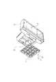
図1は本発明の好適な一実施の形態を示している。本形態において、車載装置の固定具は、表示パネル91を有する車載装置9などの基部へ着脱可能に組み付けてダッシュボード等へ固定させるものであって、基台1とジョイントベース2とを備える。ジョイントベース2を車載装置9へ連係させ、基台1上で車載装置9の姿勢の変更を自在にした支持を行わせる構成になっている。 FIG. 1 shows a preferred embodiment of the present invention. In this embodiment, the fixture of the in-vehicle device is detachably assembled to a base such as the in-vehicle device 9 having the
ジョイントベース2には、略長方形状の板材21の裏面にボールジョイント22を一体に設ける。これは車載装置9の底面の取り付け部92に板材21が嵌め合い、着脱が自在に行えるようにしている。基台1の上面には図2(b)に示すように、ボールジョイント22の受け座11を設け、ジョイントベース2の姿勢変更が自在に行える構成になっている。 The
基台1の底面には粘着性シート3を取り付けている。この粘着性シート3は、柔軟性が高いゲル状のシート材からなり、吸盤31を多数配列させて形成している。この配置する吸盤の個数は、実施形態では、16個としているが、その数は任意に設定でき、16個よりも少なくても良いし、多くても良い。また、配列パターンも、碁盤の目(格子状の交点)に規則正しく小さい仮想正方形の各頂点に配列するものに限ることはなく、格子状の交点であっても、仮想長方形の各頂点に配列しても良いし、さらには、格子状ではなく、任意の配置パターンを取ることができる。そして、配置バランスも全体で均等にしても良いし、適宜アンバランスにしても良い。 An
吸盤31は、放物線状などのなめらかな曲面形状のくぼみ32と、当該くぼみ32を囲む環状の隆起部33とからなり、寸法サイズは図2(a)に示すように、粘着性シート3の表面サイズに対して1/4から1/16程度の大きさとすることが好ましい。本実施形態では、図1,図2等に示すように、吸盤31を4×4に整列させ、合計16個を用いていることから、個々の吸盤31は、粘着性シート3の表面サイズに対して1/16程度の寸法に設定している。実施形態では、全ての吸盤31のサイズを同じサイズとしているが、異ならせても良い。但し、高さについてはあまりその差が大きいと個々の吸盤が適切に取付面に接触できなくなるおそれもあるので、等しいかその差を少なく抑える必要がある。 The
これら吸盤31は隣り合う間隔を最小限に狭く設定し、粘着性シート3の表面に対して最大数が並ぶ配列とする。また、並び列については図2(c)に示すように、吸盤31の配列は隣との間に谷間部分を設定し、隆起部33が互いに干渉しない並び列になっている。 The suction cups 31 are set so that the interval between adjacent ones is set to a minimum and the maximum number is aligned with the surface of the
この吸盤31の寸法形状は、各種に設定できるが、例えば、直径は5mm〜20mmとし、深さは1mm〜5mmとすることができる。係る寸法形状の場合、特に、固定対象(取付面)がダッシュボードにした場合に好適となる(高さを低く抑えつつ、十分な吸着力を発揮できる)。 The size and shape of the
なお、本実施形態では、各吸盤の寸法形状を同一にしたが、適宜異ならせ、複数種類の形態からなる吸盤を適宜の配置にすることもできる。 In addition, in this embodiment, although the dimension shape of each suction cup was made the same, it can also be changed suitably and the suction cup which consists of multiple types of forms can also be arranged suitably.
粘着性シート3(ゲル状のシート材)は、ポリエチレン系やスチレン系あるいはシリコン系の合成樹脂材料から形成し、これは車両のダッシュボードへ装着した際の使用環境を考慮した耐候性を有するものが好ましい。また、金型を用いた量産性を考慮する必要もあり、ゲル状のシート材は熱可塑性を有するとともに熱硬化性を有するものが好ましい。車内の温度は夏期では80℃程度に上昇するので、合成樹脂材料としては溶融温度が車内温度よりも十分に大きい値、例えば150℃以上の値を有するものが好ましい。 The pressure-sensitive adhesive sheet 3 (gel-like sheet material) is formed from a polyethylene, styrene, or silicon-based synthetic resin material, and has weather resistance in consideration of the use environment when mounted on a vehicle dashboard. Is preferred. In addition, it is necessary to consider mass productivity using a mold, and it is preferable that the gel-like sheet material has thermoplasticity and thermosetting properties. Since the temperature inside the vehicle rises to about 80 ° C. in summer, the synthetic resin material preferably has a melting temperature sufficiently higher than the vehicle temperature, for example, a value of 150 ° C. or more.
粘着性シート3は図3に示すように、基台1の底面に組み付けることになる。この組み付けは、接着剤を用いて貼り付けてもよいが、ゲル状のシート材が有している粘着力により粘着させる構成にすることもできる。また、粘着性シート3の裏側の組み付け面にも吸盤31を配列させて形成し、それら吸盤31の吸着力により基台1の底面に吸着させる構成にしてもよい。さらに、粘着性シート3は、基台1の底面に対して異種材料の一体化成形により一体に形成する構成にしてもよい。 The
本発明に係る固定具は、図4に各部を分離して示しているが、ジョイントベース2および基台1が車載装置9の基部に連係して組み付くことになる。そして、ダッシュボード等への装着には、基台1を目標位置へ位置合わせして単に上から押さえ込むだけでよく、粘着性シート3の吸盤31が吸着することで固定が完了する。 The fixing device according to the present invention is shown with the respective parts separated in FIG. 4, but the
車載装置9は図4に示すように、本体の上面にカードスロット93を設け、メモリカードを押し込み操作するようにしている。この本体の上面に配置する操作部は、押し込み操作する操作部が好ましく、例えば押しボタンスイッチなどがある。カードスロット93は、取り出し操作のためのバネ機構を有する構成とし、メモリカードを挿入した際にバネ機構が作用力をロックし、取り出しはメモリカードを引き出し操作するのではなく、再度押し込み操作することでバネ機構のロックが解除し、取り出しが行えるようにしている。 As shown in FIG. 4, the in-vehicle device 9 is provided with a
本実施形態では、カードスロット93などの押し込み操作部を本体の上面に配置したため、以下の作用効果を奏する。すなわち、ダッシュボード等へ固定した装着状態において、メモリカードの装着操作を比較的に頻繁に行うことになるため、押し込み操作の力が本体側から基台1側へ加わることになる。この力は粘着性シート3を押しつける作用力となるので、押し込み操作部を操作するたびに吸盤31の吸着を増補でき、固着を強固にすることができる。 In the present embodiment, the pushing operation unit such as the
本発明にあっては、粘着性シート3はゲル状のシート材からなるのでそもそも柔軟性が高く、ダッシュボードの表面のような曲面形成の相手面へ良好に密着させることができ、フィット性がよい。また、柔軟性が高いゲル状のシート材なので振動の吸収作用があり、車両の振動を良好に吸収できる。そして、粘着性シート3には多数(例えば16個)の吸盤31を配列させるので、それら吸盤31により相手面へ吸着させることができ、それらの吸着力でもって固定が行える。 In the present invention, since the pressure-
ゲル状のシート材は、上述したように車室内の使用環境を考慮した材料選定を行うものであり、ポリエチレン系やスチレン系あるいはシリコン系の合成樹脂材料によれば十分な耐候性を得ることができる。したがって、車室内での温度変化には良好に対応でき、柔軟性が高いという基本性質は安定的に発現する。 As described above, the gel-like sheet material is selected in consideration of the use environment in the passenger compartment, and sufficient weather resistance can be obtained by using a polyethylene-based, styrene-based, or silicon-based synthetic resin material. it can. Therefore, the basic property of being able to cope with the temperature change in the passenger compartment and having high flexibility is expressed stably.
吸盤31それぞれでは、くぼみ32が放物線状などのなめらかな曲面形状なので、押しつけ時に相手面へ良好に密着でき、空気がスムーズに抜き出る。このため、吸盤31は相手面へ良好にフィットさせることができ、吸着力を強く得ることができる。 In each of the
複数の吸盤31は、隣との間に谷間部分を設定し、隆起部33が互いに干渉しない並び列にするので、くぼみ32からの空気の排出が干渉することなく行えて吸着力を安定に得ることができる。これら吸盤31は隣り合う間隔を最小限に狭く設定し、粘着性シート3の表面に対して最大数が並ぶ配列とするので、吸着力を最大限に得ることができる。 The plurality of
したがって、本発明に係る固定具によれば、曲面形成のダッシュボードの表面へ良好にフィットでき、車両の振動や温度変化など過酷な条件下でも吸着力を安定に得ることができる。その結果、固定が強固に行える Therefore, according to the fixture according to the present invention, it is possible to satisfactorily fit to the surface of the curved dashboard, and the adsorption force can be stably obtained even under severe conditions such as vehicle vibration and temperature change. As a result, it can be firmly fixed
この場合、粘着性シート3が部材として持つ柔軟性,粘着性を利用し、複数を配列させた吸盤31の吸着力を利用しているので、従来の両面粘着テープを用いた貼り付けとは違って貼り直しが容易であり、はがした後の表面の汚損はもちろんない。 In this case, since the
また、ジョイントベース2にボールジョイント22を設けて基台1と連結するので、車載装置9の姿勢の変更が容易であり自由度が高い。姿勢の変更を行う操作では、ボールジョイント22の動きが受け座11から基台1の底面側へ伝わるので、これは吸盤31を押しつける作用力になる。したがって、車載装置9の姿勢を変更操作するたびに吸盤31の吸着を増補でき、固着を強固にすることができる。 In addition, since the ball joint 22 is provided on the
粘着性シート3は図5に示すように、略方形に形成し、車載装置9に対して直に組み付ける構成を採ることもよい。つまり、粘着性シート3は、車載装置9の底面の取り付け部92に嵌め合う形状とし、取り付け部92へ直接に組み付ける構成にする。この場合、基台1を利用しない構成なので、ダッシュボード等への装着において全体の高さを低くすることができ、利用者が望む適切な高さにすることができる。 As shown in FIG. 5, the
そして、基台1は図6に示すように、底面の取り付け部を略方形に形状変更し、図5に示す略方形の粘着性シート3を組み付ける構成にすることもできる。このような構成によれば、粘着性シート3は基台1に対して、あるいは車載装置9の取り付け部92に対して、選択的に組み付けすることができる。したがって、装着形態(装着高さ)の選択肢が増し、利用者の選択の自由度を大きくできる。例えば車載装置9がGPS受信機などでは、電波の受信状態が良好となる高さを選択でき、あるいは表示の見やすい高さを選択するなど、装着形態を容易に変更でき、適切な高さにすることができる。 And the base 1 can also be set as the structure which attaches the substantially square
また、粘着性シート3には吸盤31を設けない構成とし、当該ゲル状のシート材がもともと有している粘着性を利用する構成にすることでもよい。この場合でも、例えば、車載装置9の姿勢を変更したり、上面(例えば、カードスロット部分)を下方に向けて押したりする作用により、使用時にも接着力・粘着力が強められ、長期にわたり固定をしっかり行なえるという効果を発揮することができる。 Alternatively, the
なお、表示パネルの寸法形状は、大小各種のものを用いることができる。また、本発明の車載装置は、必ずしも表示装置を備えていなくても良い。但し、本実施形態では、多数の吸盤を配列したことにより、固定具の高さを低く抑えることと、全体の吸着力を大きくすることができたことに鑑みると、表示パネルを備えた車載装置は好ましいものの一つとなる。 Note that the size and shape of the display panel can be large or small. Moreover, the vehicle-mounted apparatus of this invention does not necessarily need to be provided with the display apparatus. However, in the present embodiment, in view of the fact that by arranging a large number of suction cups, the height of the fixture can be kept low and the overall suction force can be increased, an in-vehicle device provided with a display panel Is one of the preferred ones.
なおまた、上記の実施形態では、1枚の粘着シートを用いて構成したが、複数枚用いることもできる。一例としては、車載装置の底面の取り付け部と、基台の底面の取り付け部との双方に、それぞれ粘着性シートの形状に合う粘着シート取り付け部を有するようにして対応できる。 In the above embodiment, a single adhesive sheet is used, but a plurality of sheets can be used. As an example, both the attachment portion on the bottom surface of the in-vehicle device and the attachment portion on the bottom surface of the base can be handled by having an adhesive sheet attachment portion that matches the shape of the adhesive sheet.
1 基台
11 受け座
2 ジョイントベース
21 板材
22 ボールジョイント
3 粘着性シート
31 吸盤
32 くぼみ
33 隆起部
9 車載装置
91 表示パネル
92 取り付け部
93 カードスロット
DESCRIPTION OF SYMBOLS 1
Claims (5)
Translated fromJapanese前記車載装置を支持してダッシュボード上へ固定する固定具と
を備える固定機構であって、
前記ダッシュボード上への固定は、前記固定具の底面に柔軟性を有するゲル状のシート材からなる粘着性シートを取り付けて行うものであり、
前記車載装置は、その上面に押し込み操作を行う操作部を有する構成としたものであることを特徴とする固定機構。An in-vehicle device;
A fixing mechanism that supports the in-vehicle device and fixes it on the dashboard,
Fixing on the dashboard is performed by attaching an adhesive sheet made of a gel-like sheet material having flexibility to the bottom surface of the fixture,
The in-vehicle device is configured to have an operation unit that performs a pushing operation on an upper surface thereof.
を特徴とする請求項1に記載の固定機構。The fixing mechanism according to claim 1, further comprising a card slot as the operation unit.
を特徴とする請求項2に記載の固定機構。The card slot is configured to have a spring mechanism for removing the memory card, and when the memory card is inserted, the spring mechanism locks the acting force, so that the memory card is not pushed out but pushed out again. The fixing mechanism according to claim 2, wherein the spring mechanism is unlocked and can be taken out.
を特徴とする請求項1〜3のいずれかに記載の固定機構。The fixing mechanism according to claim 1, further comprising a push button switch as the operation unit.
を特徴とする請求項1〜4のいずれかに記載の固定機構。
5. The adhesive sheet is formed by arranging a plurality of suction cups each including a concave portion having a smooth curved shape such as a parabolic shape and an annular ridge portion surrounding the concave portion. The fixing mechanism described.
Priority Applications (1)
| Application Number | Priority Date | Filing Date | Title |
|---|---|---|---|
| JP2013070844AJP5651897B2 (en) | 2013-03-29 | 2013-03-29 | In-vehicle device fixture |
Applications Claiming Priority (1)
| Application Number | Priority Date | Filing Date | Title |
|---|---|---|---|
| JP2013070844AJP5651897B2 (en) | 2013-03-29 | 2013-03-29 | In-vehicle device fixture |
Related Parent Applications (1)
| Application Number | Title | Priority Date | Filing Date |
|---|---|---|---|
| JP2008063988ADivisionJP5246616B2 (en) | 2008-03-13 | 2008-03-13 | In-vehicle device fixture |
Publications (2)
| Publication Number | Publication Date |
|---|---|
| JP2013177125Atrue JP2013177125A (en) | 2013-09-09 |
| JP5651897B2 JP5651897B2 (en) | 2015-01-14 |
Family
ID=49269240
Family Applications (1)
| Application Number | Title | Priority Date | Filing Date |
|---|---|---|---|
| JP2013070844AActiveJP5651897B2 (en) | 2013-03-29 | 2013-03-29 | In-vehicle device fixture |
Country Status (1)
| Country | Link |
|---|---|
| JP (1) | JP5651897B2 (en) |
Cited By (1)
| Publication number | Priority date | Publication date | Assignee | Title |
|---|---|---|---|---|
| CN113022456A (en)* | 2021-03-03 | 2021-06-25 | 高丽萍 | Anti-shake car navigator based on thing networking |
Families Citing this family (1)
| Publication number | Priority date | Publication date | Assignee | Title |
|---|---|---|---|---|
| CN108263402B (en)* | 2018-01-30 | 2019-09-13 | 石美秀 | A kind of bullet train is with can damping instrument |
Citations (5)
| Publication number | Priority date | Publication date | Assignee | Title |
|---|---|---|---|---|
| JPS59188A (en)* | 1982-06-24 | 1984-01-05 | シャープ株式会社 | Portable general-purpose electronic apparatus |
| JPS6119120U (en)* | 1984-07-09 | 1986-02-04 | 有限会社相互ゴム製作所 | Holder with double-sided suction cup |
| JP2002171461A (en)* | 2000-11-30 | 2002-06-14 | Sony Corp | Monitoring device and base unit |
| JP2005198042A (en)* | 2004-01-07 | 2005-07-21 | Sharp Corp | Image display device |
| JP2006347138A (en)* | 2005-06-20 | 2006-12-28 | Sony Corp | Manufacturing process of suction cup, suction cup and in-vehicle instrument |
- 2013
- 2013-03-29JPJP2013070844Apatent/JP5651897B2/enactiveActive
Patent Citations (5)
| Publication number | Priority date | Publication date | Assignee | Title |
|---|---|---|---|---|
| JPS59188A (en)* | 1982-06-24 | 1984-01-05 | シャープ株式会社 | Portable general-purpose electronic apparatus |
| JPS6119120U (en)* | 1984-07-09 | 1986-02-04 | 有限会社相互ゴム製作所 | Holder with double-sided suction cup |
| JP2002171461A (en)* | 2000-11-30 | 2002-06-14 | Sony Corp | Monitoring device and base unit |
| JP2005198042A (en)* | 2004-01-07 | 2005-07-21 | Sharp Corp | Image display device |
| JP2006347138A (en)* | 2005-06-20 | 2006-12-28 | Sony Corp | Manufacturing process of suction cup, suction cup and in-vehicle instrument |
Cited By (1)
| Publication number | Priority date | Publication date | Assignee | Title |
|---|---|---|---|---|
| CN113022456A (en)* | 2021-03-03 | 2021-06-25 | 高丽萍 | Anti-shake car navigator based on thing networking |
Also Published As
| Publication number | Publication date |
|---|---|
| JP5651897B2 (en) | 2015-01-14 |
Similar Documents
| Publication | Publication Date | Title |
|---|---|---|
| JP5246616B2 (en) | In-vehicle device fixture | |
| JP4862559B2 (en) | Sucker | |
| JP2008051296A (en) | Sucker | |
| JP4862289B2 (en) | Suction cup and in-vehicle equipment | |
| TWI401383B (en) | Holder and sucker thereof | |
| KR20080018831A (en) | Sucker | |
| CN201800608U (en) | Cup stand device | |
| JP2008028016A5 (en) | ||
| CA2922857A1 (en) | Suction cup mount | |
| JP5651897B2 (en) | In-vehicle device fixture | |
| CN212785466U (en) | Vehicle-mounted mobile phone support | |
| KR200483942Y1 (en) | Mobile Phone Cradle for Cars | |
| JP5125687B2 (en) | Suction cup and suction cup device | |
| JP4903832B2 (en) | On-vehicle equipment fittings and equipment | |
| KR20130071039A (en) | Supporter for electronic equipment in vehicle | |
| KR100921437B1 (en) | Navigation structure | |
| JP2009039374A (en) | Adhesive mat and support device with adhesive suction cups | |
| JP5352778B2 (en) | Mounting device and device for in-vehicle equipment | |
| KR101314849B1 (en) | Fixing device for portable instrument | |
| KR20160048736A (en) | Mobile Phone Cradle for Cars | |
| KR20150082756A (en) | Mobile-device dock | |
| JP3144534U (en) | Multi holder | |
| JP2007132411A (en) | Support for on-vehicle receiver | |
| CN101885311B (en) | bracket | |
| CN202619071U (en) | product holder |
Legal Events
| Date | Code | Title | Description |
|---|---|---|---|
| A131 | Notification of reasons for refusal | Free format text:JAPANESE INTERMEDIATE CODE: A131 Effective date:20140318 | |
| A521 | Request for written amendment filed | Free format text:JAPANESE INTERMEDIATE CODE: A523 Effective date:20140418 | |
| A02 | Decision of refusal | Free format text:JAPANESE INTERMEDIATE CODE: A02 Effective date:20140703 | |
| A521 | Request for written amendment filed | Free format text:JAPANESE INTERMEDIATE CODE: A523 Effective date:20140718 | |
| A911 | Transfer to examiner for re-examination before appeal (zenchi) | Free format text:JAPANESE INTERMEDIATE CODE: A911 Effective date:20140903 | |
| TRDD | Decision of grant or rejection written | ||
| A01 | Written decision to grant a patent or to grant a registration (utility model) | Free format text:JAPANESE INTERMEDIATE CODE: A01 Effective date:20141002 | |
| A61 | First payment of annual fees (during grant procedure) | Free format text:JAPANESE INTERMEDIATE CODE: A61 Effective date:20141030 | |
| R150 | Certificate of patent or registration of utility model | Ref document number:5651897 Country of ref document:JP Free format text:JAPANESE INTERMEDIATE CODE: R150 | |
| S531 | Written request for registration of change of domicile | Free format text:JAPANESE INTERMEDIATE CODE: R313531 | |
| R350 | Written notification of registration of transfer | Free format text:JAPANESE INTERMEDIATE CODE: R350 | |
| R250 | Receipt of annual fees | Free format text:JAPANESE INTERMEDIATE CODE: R250 |