JP2013176840A - Control method for electrical tool and electrical tool executing the same - Google Patents
Control method for electrical tool and electrical tool executing the sameDownload PDFInfo
- Publication number
- JP2013176840A JP2013176840AJP2013099916AJP2013099916AJP2013176840AJP 2013176840 AJP2013176840 AJP 2013176840AJP 2013099916 AJP2013099916 AJP 2013099916AJP 2013099916 AJP2013099916 AJP 2013099916AJP 2013176840 AJP2013176840 AJP 2013176840A
- Authority
- JP
- Japan
- Prior art keywords
- predetermined
- current
- derivative
- electric tool
- control signal
- Prior art date
- Legal status (The legal status is an assumption and is not a legal conclusion. Google has not performed a legal analysis and makes no representation as to the accuracy of the status listed.)
- Pending
Links
- 238000000034methodMethods0.000titleclaimsabstractdescription32
- 230000004044responseEffects0.000claimsdescription6
- 239000000463materialSubstances0.000claimsdescription3
- 230000003111delayed effectEffects0.000claims1
- 210000003127kneeAnatomy0.000description11
- 230000000875corresponding effectEffects0.000description10
- 238000010586diagramMethods0.000description10
- 239000002023woodSubstances0.000description10
- 230000008569processEffects0.000description4
- 230000001276controlling effectEffects0.000description3
- 238000001514detection methodMethods0.000description3
- 238000005259measurementMethods0.000description3
- 230000036962time dependentEffects0.000description3
- 230000008859changeEffects0.000description2
- 230000001681protective effectEffects0.000description2
- 239000003990capacitorSubstances0.000description1
- 238000005553drillingMethods0.000description1
- 230000000694effectsEffects0.000description1
- 239000011121hardwoodSubstances0.000description1
- 238000004519manufacturing processMethods0.000description1
- 230000009467reductionEffects0.000description1
- 239000011122softwoodSubstances0.000description1
Images


Classifications
- B—PERFORMING OPERATIONS; TRANSPORTING
- B25—HAND TOOLS; PORTABLE POWER-DRIVEN TOOLS; MANIPULATORS
- B25B—TOOLS OR BENCH DEVICES NOT OTHERWISE PROVIDED FOR, FOR FASTENING, CONNECTING, DISENGAGING OR HOLDING
- B25B23/00—Details of, or accessories for, spanners, wrenches, screwdrivers
- B25B23/14—Arrangement of torque limiters or torque indicators in wrenches or screwdrivers
- B25B23/147—Arrangement of torque limiters or torque indicators in wrenches or screwdrivers specially adapted for electrically operated wrenches or screwdrivers
- B—PERFORMING OPERATIONS; TRANSPORTING
- B23—MACHINE TOOLS; METAL-WORKING NOT OTHERWISE PROVIDED FOR
- B23P—METAL-WORKING NOT OTHERWISE PROVIDED FOR; COMBINED OPERATIONS; UNIVERSAL MACHINE TOOLS
- B23P19/00—Machines for simply fitting together or separating metal parts or objects, or metal and non-metal parts, whether or not involving some deformation; Tools or devices therefor so far as not provided for in other classes
- B23P19/04—Machines for simply fitting together or separating metal parts or objects, or metal and non-metal parts, whether or not involving some deformation; Tools or devices therefor so far as not provided for in other classes for assembling or disassembling parts
- B23P19/06—Screw or nut setting or loosening machines
- B23P19/065—Arrangements for torque limiters or torque indicators in screw or nut setting machines
- B23P19/066—Arrangements for torque limiters or torque indicators in screw or nut setting machines by electrical means
- B—PERFORMING OPERATIONS; TRANSPORTING
- B25—HAND TOOLS; PORTABLE POWER-DRIVEN TOOLS; MANIPULATORS
- B25B—TOOLS OR BENCH DEVICES NOT OTHERWISE PROVIDED FOR, FOR FASTENING, CONNECTING, DISENGAGING OR HOLDING
- B25B23/00—Details of, or accessories for, spanners, wrenches, screwdrivers
- B25B23/14—Arrangement of torque limiters or torque indicators in wrenches or screwdrivers
- B—PERFORMING OPERATIONS; TRANSPORTING
- B25—HAND TOOLS; PORTABLE POWER-DRIVEN TOOLS; MANIPULATORS
- B25B—TOOLS OR BENCH DEVICES NOT OTHERWISE PROVIDED FOR, FOR FASTENING, CONNECTING, DISENGAGING OR HOLDING
- B25B21/00—Portable power-driven screw or nut setting or loosening tools; Attachments for drilling apparatus serving the same purpose
- B25B21/008—Portable power-driven screw or nut setting or loosening tools; Attachments for drilling apparatus serving the same purpose with automatic change-over from high speed-low torque mode to low speed-high torque mode
Landscapes
- Engineering & Computer Science (AREA)
- Mechanical Engineering (AREA)
- Details Of Spanners, Wrenches, And Screw Drivers And Accessories (AREA)
- Portable Power Tools In General (AREA)
- Control Of Electric Motors In General (AREA)
Abstract
Description
Translated fromJapanese本発明は、回転速度を生成するために電流が供給される好ましくは電気ドライバ(ねじ廻し)である電気工具を制御する方法に関する。本発明は、また、本方法を実行するための、好ましくは電気ドライバである電気工具に関する。 The present invention relates to a method for controlling an electric tool, preferably an electric screwdriver, which is supplied with an electric current to generate a rotational speed. The invention also relates to an electric tool, preferably an electric driver, for carrying out the method.
現在のところ、電気ドライバのような動力工具は、搭載される電源からの供給電流を介して、回転モータにより駆動され、木のボード内へとねじ込む。スクリューは、異なる直径を有してもよい。異なるスクリューのヘッドの形状は互いに異なる。従って、同一の期のボードに異なるスクリューが駆動されるときに異なる状況が生ずるだろう。更に、同一のスクリューが異なる材料内に駆動される場合、異なる木の片の硬さが異なりうり、電気ドライバの電流は異なるだろう。通常、ドライバの使用中、ユーザは、ワーク近傍の表面までスクリューヘッドで穴あけすべきであり、ユーザは、スクリューヘッドが端部に到達するときにモータを停止させるために非常に注意深く穴あけプロセスを監視する必要がある。従って、スクリューは、木の片内へと深く行き過ぎない望ましくない場合がある。その他の場合、スクリューヘッドが木のボード内へと不注意にねじ込まれたときの過負荷からモータを防止することができる。 At present, a power tool such as an electric driver is driven by a rotary motor via a supply current from an installed power source and screwed into a wooden board. The screws may have different diameters. Different screw heads have different shapes. Thus, different situations will arise when different screws are driven on the same board. Furthermore, if the same screw is driven into different materials, the hardness of the different pieces of wood will vary and the current of the electric driver will be different. Normally, during use of the driver, the user should drill with a screw head to the surface near the workpiece, and the user will monitor the drilling process very carefully to stop the motor when the screw head reaches the end There is a need to. Thus, the screw may not be desirable because it does not go too far into the piece of wood. In other cases, the motor can be prevented from overloading when the screw head is inadvertently screwed into a wooden board.
ある過負荷保護デバイスを使用するのは従来技術である。これは、モータ電流が所定の制限値を超えるときにドリルを駆動モータから外す機械的なクラッチであってよい。回転可能で複数のスケールでマークされたトルクカラーは、かかる過負荷保護デバイスを有する動力工具のハウジングの前側に設けられる。これらのスケールは、トルク制限を指示する。ユーザは、回転可能なトルクカラーにより制限トルク値を事前に設定すべきであり、出力トルクが所定の値に達し若しくは所定の値を超えたときに、クラッチは、自動的に動力工具のドリルとモータの係合を解除し始めるだろう。更に、ある過負荷保護デバイスを備える電気ドライバは、ハウジングの前端から延在するスリーブを有し、スリーブの前端は、電気ドライバのドリルの前端と位置が合っている。スクリューヘッドが木のボード表面に到達するとき、スリーブの前端もそれに到達し、もしスクリューが更に押された場合は、スリーブが、ハウジング内のクラッチを作動するように付勢され、これにより、ドリルとモータの係合を解除する。しかし、上述の機械的なクラッチは、構造が複雑であり、複雑化され、製造もコストがかかる。 The use of certain overload protection devices is prior art. This may be a mechanical clutch that disconnects the drill from the drive motor when the motor current exceeds a predetermined limit value. A torque collar which is rotatable and marked on a plurality of scales is provided on the front side of the housing of a power tool having such an overload protection device. These scales indicate torque limits. The user should pre-set a limit torque value with a rotatable torque collar, and when the output torque reaches or exceeds a predetermined value, the clutch automatically The motor will start to disengage. In addition, an electrical driver with certain overload protection devices has a sleeve extending from the front end of the housing, the front end of the sleeve being aligned with the front end of the drill of the electrical driver. When the screw head reaches the wooden board surface, the front end of the sleeve also reaches it, and if the screw is pushed further, the sleeve is biased to actuate the clutch in the housing, thereby And disengage the motor. However, the above-described mechanical clutch has a complicated structure, is complicated, and is expensive to manufacture.
本発明の目的は、ドリルにより作動されるワークが所定の位置に到達することを工具において確かにし、ワークがこの位置を超えていかないことを確かにする電気工具用方法を提供することである。 An object of the present invention is to provide a method for an electric tool that ensures in a tool that a workpiece actuated by a drill reaches a predetermined position and that the workpiece does not exceed this position.
また、本発明の目的は、かかる方法が実現されることができる上述の種の工具を提供することである。 It is also an object of the present invention to provide a tool of the above kind in which such a method can be realized.
本発明の一局面によれば、回転速度を生成するために電流が供給される電気工具を制御する方法であって、
時間に依存して前記電気工具に供給される電流を測定するステップと、
前記時間に依存した電流の2次若しくはn次(n≧3)導関数を形成するステップと、
前記2次若しくはn次導関数に従って制御信号を生成するステップと、
前記制御信号に応じて前記電気工具の回転速度を変化するステップとを含む、方法が提供される。According to one aspect of the present invention, a method for controlling an electric tool that is supplied with current to generate a rotational speed comprising:
Measuring the current supplied to the electric tool as a function of time;
Forming a second-order or n-order (n ≧ 3) derivative of the time-dependent current;
Generating a control signal according to the second or n th derivative;
Changing the rotational speed of the electric tool in response to the control signal.
本発明のその他の局面によれば、回転速度をドリルが得るように、ドリルを駆動するモータと、
前記モータに電流を供給する源と、
前記電流を測定するセンサと、
時系列の前記電流の勾配の変動の2次若しくはn次導関数でのパルスの検出を行って制御信号を生成すると共に、前記制御信号に応じて前記ドリルの回転速度を変更する制御手段とを含む、電気工具が提供される。According to another aspect of the present invention, a motor for driving the drill so that the drill obtains the rotational speed;
A source for supplying current to the motor;
A sensor for measuring the current;
A control means for generating a control signal by detecting a pulse with a second-order or n-th derivative of a variation in the gradient of the current in time series, and a control means for changing a rotation speed of the drill according to the control signal; An electric tool is provided.
本発明の一局面によれば、回転速度を生成するために電流が供給される電気工具を制御する方法であって、
a.所定の時点で前記電気工具に供給される電流を測定するステップと、
b.前記所定の時点で、
b1)前記測定した電流が所定の第1の閾値よりも低い場合に第1の所定の導関数値を選択し、
b2)前記測定した電流が前記所定の第1の閾値よりも高い場合に前記第1の所定の導関数値よりも高い第2の所定の導関数値を、選択するステップと、
c.時間に依存した前記電流の1次導関数を形成するステップと、
d.前記1次導関数が前記第1若しくは第2の所定の導関数値に到達したときに前記1次導関数から制御信号を生成するステップと、
e.前記制御信号に応答して前記電気工具の回転速度を変更するステップとを含む、方法が提供される。According to one aspect of the present invention, a method for controlling an electric tool that is supplied with current to generate a rotational speed comprising:
a. Measuring the current supplied to the electric tool at a predetermined time;
b. At the predetermined time,
b1) selecting a first predetermined derivative value when the measured current is lower than a predetermined first threshold;
b2) selecting a second predetermined derivative value higher than the first predetermined derivative value when the measured current is higher than the predetermined first threshold;
c. Forming a first derivative of the current as a function of time;
d. Generating a control signal from the first derivative when the first derivative reaches the first or second predetermined derivative value;
e. Changing the rotational speed of the electric tool in response to the control signal.
本発明のその他の局面によれば、電気工具は、
a)回転速度をドリルが得るように、ドリルを駆動するモータと、
b)前記モータに電流を供給する源と、
c)前記電流を測定するセンサと、
d)制御手段とを含んでよく、
該制御手段は、
d1)時系列の前記電流の勾配の変動を検出し、
d2)所定の時点での前記電流の値に応じて第1若しくは第2の所定の導関数値を選択し、
d3)前記第1若しくは第2の所定の導関数値から制御信号を生成し、
d4)前記制御信号に応答して前記電気工具の回転速度を変更する。According to another aspect of the present invention, an electric tool is:
a) a motor that drives the drill so that the drill obtains the rotational speed;
b) a source for supplying current to the motor;
c) a sensor for measuring the current;
d) a control means,
The control means includes
d1) detecting a variation in the gradient of the current in time series;
d2) selecting a first or second predetermined derivative value according to the value of the current at a predetermined time point;
d3) generating a control signal from the first or second predetermined derivative value;
d4) The rotational speed of the electric tool is changed in response to the control signal.
先行技術と比較すると、本発明は、電子制御手段を設けることによってドリルにより作動されるワークが所定位置に到達するか否かを自動的に検出する。スクリューが木の片内へと駆動され、ワークが当該位置に到達したことが検出され変更作動を実行すると所定位置を超えて行かないことを保証することができる。複雑な機械的クラッチが存在せず、従って、作成が簡易であり、コストが低減される。 Compared with the prior art, the present invention automatically detects whether or not the workpiece actuated by the drill reaches a predetermined position by providing the electronic control means. When the screw is driven into a piece of wood, it is detected that the workpiece has reached the position and a change operation is performed, it can be ensured that the predetermined position is not exceeded. There are no complex mechanical clutches, thus making it simple and reducing costs.
本発明の制御方法は、多くの種類の動力工具で使用するために適合される。電気ドライバが以下の好ましい実施例として説明される。 The control method of the present invention is adapted for use with many types of power tools. An electrical driver is described as the preferred embodiment below.
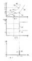
図1によれば、電気ドライバのi(t)の図が示される。図4に関して、ユーザは、この実施例ではスクリューである作業ヘッド14であって、木のボード16内に駆動されることになる作業ヘッド14に対してドライバ2を押す。押しは、ほぼ一定の圧力で実行される。文字tは、スクリューがボード内へとねじ込まれる時間を表し、結果としてボードにおけるスクリューの位置を表す。文字iは、ドライバの電気モータに供給される電流を表し、従って、モータにより供給される力若しくは荷重を表す。 According to FIG. 1, a diagram of i (t) of an electric driver is shown. With reference to FIG. 4, the user pushes the
図1の曲線は、第1位置A,第2位置K及び第3位置Bを含む。第1位置Aは、増加する勾配であり、木のボード内へのスクリューの主本体のねじ込みプロセスを表す。この上昇は、線形的でありえ若しくはわずかに湾曲若しくは曲線となりえる。第2部位は、第1部位Aに後続する。それは、膝部Kと称される。この膝部Kは、傾斜の正の変動である。即ち、それは、第1部位Aに対する上方の上昇を有する急な変動である。これは、スクリューヘッドによる木ボードの表面への接触し始めを表す。第3部位Bは、膝部Kに後続する。この上昇は、同様に、線形的でありえ若しくはわずかに湾曲若しくは曲線となりえる。しかし、曲線Bは、曲線Aよりも非常に急峻である。 The curve in FIG. 1 includes a first position A, a second position K, and a third position B. The first position A is an increasing gradient, representing the process of screwing the main body of the screw into the wooden board. This rise can be linear or slightly curved or curved. The second part follows the first part A. It is referred to as knee K. This knee K is a positive variation in inclination. That is, it is a steep fluctuation with an upward rise relative to the first site A. This represents the beginning of contact with the surface of the wood board by the screw head. The third part B follows the knee K. This rise can likewise be linear or slightly curved or curved. However, curve B is much steeper than curve A.
実際、図1に示す曲線は、本発明の制御方法を実行しない動力工具の作動状態を表し、曲線の第3部位は、高い電流が動力工具内で生成されヘッドさえも木片内に挿入することをもたらしうることを表す。それゆえに、膝部Kに後続するかかる過剰な電流を防止する手段を講ずることが肝要である。 In fact, the curve shown in FIG. 1 represents the operating state of a power tool that does not perform the control method of the present invention, and the third part of the curve is that high current is generated in the power tool and even the head is inserted into the piece of wood. That can bring Therefore, it is important to take measures to prevent such excessive current following the knee K.
スクリューが膝部Kに対応する位置までねじ込まれるとき、更なるねじ込みは、スクリューヘッドを木のボード内に挿入することになり、モータにダメージを与えうる。それゆえに、本発明は、膝部Kの自動的な検出に基づき、その際、自動的に事前防止策を開始する。 When the screw is screwed to the position corresponding to the knee K, further screwing will insert the screw head into the wooden board and may damage the motor. Therefore, the present invention is based on the automatic detection of the knee K, at which time it automatically starts a precaution.
膝部Kの検出は、この実施例では、図2及び3を参照して説明される。 The detection of the knee K is described in this embodiment with reference to FIGS.
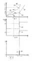
図2では、図1の図の時間tに対する電流iの1次導関数di/dtが示される。図1の第1及び第3部位A,Bは、それぞれ、この図におけるtの基本ラインに平行な対応するラインである一方、第2部位Kは、この図における鋭い正の増加若しくは上昇曲線である。 In FIG. 2, the first derivative di / dt of the current i with respect to time t in the diagram of FIG. 1 is shown. The first and third parts A and B in FIG. 1 are respectively corresponding lines parallel to the basic line t in this figure, while the second part K is a sharp positive increase or rise curve in this figure. is there.
図2によれば、図1に示す電流iの2次導関数d2i/dt2は、時間に依存して形成される。第1及び第3部位の値は、2回微分された後はゼロであるが、第2部位Kは、下方に開口する放物線として示される。ピーク信号pの種は、放物線の上部領域で形成され、これは、頂点を含む特定の領域である。図4に関して、制御信号sは、ピーク信号pが形成されたときに生成される。当然、好ましい実施例では、所定の閾値vが設定される。制御信号sは、ピーク信号pが正であり且つ所定の閾値vを超えた場合にのみ生成される。当業者には容易であるように、制御信号sは、時間に依存する電流iの1次導関数が形成された後に生成されてもよい。例えば、キャパシタを介して、制御信号sは、所定の閾値を超える1次導関数の検出後に生成される。According to FIG. 2, the second derivative d2 i / dt2 of the current i shown in FIG. 1 is formed as a function of time. The values of the first and third parts are zero after being differentiated twice, but the second part K is shown as a parabola that opens downward. The seed of the peak signal p is formed in the upper region of the parabola, which is a specific region that includes the vertex. With reference to FIG. 4, the control signal s is generated when the peak signal p is formed. Of course, in the preferred embodiment, a predetermined threshold value v is set. The control signal s is generated only when the peak signal p is positive and exceeds a predetermined threshold value v. As is readily apparent to those skilled in the art, the control signal s may be generated after the first derivative of the time-dependent current i is formed. For example, via a capacitor, the control signal s is generated after detection of a first derivative that exceeds a predetermined threshold.
図4は、上述の制御方法を実行する電気工具を示す。ここで、以下の電気ドライバは、また、好ましい実施例として図示される。電気ドライバ2は、作業組立体4、電源18及びスイッチ20を含む。作業組立体4は、ドリル8を駆動して回転させ木のボード16内へとスクリュー14を駆動する電気モータ6を含む。作業ヘッド14は、機械的なスプリング、クラッチシステム12及びチャック10を介して直列に電気モータ6に接続される。当然、本実施例では、クラッチシステム12は省略されてもよい。本例では充電可能なバッテリ若しくはDC源である電源18は、手動トリガスイッチ20が閉であることを前提として、モータに電気のDC電流を供給する。当然、当業者には容易なように、AC電源が、本実施例のDC源に代えて使用されてもよい。 FIG. 4 shows an electric tool that performs the control method described above. Here, the following electrical driver is also illustrated as a preferred embodiment. The
電子制御デバイス22及び電流センサ24は、電源18及び電気モータ6の間に接続される。電気ドライバ2は、また、第1微分器26及び第2微分器28を含む。本実施例では、電流センサ24は、モータに供給される電流iを検出し、第1微分器26に、センサ24により測定された電流iに比例する信号を送る。この第1微分器26は、図2に示すように、時間tに依存した1次導関数di/dtを取り、1次導関数に比例した信号を生成し、次いで、当該信号を第2微分器28に送る。第2微分器28は、図3に示すような2次導関数を同様に取る。従って、第2微分器28は、上述のピーク信号pが正であり且つその値が所定の閾値vを超えるという所定の条件が生じたときに、制御信号sを生成する。実施例では、制御信号は、モータ6へのエネルギ供給を低減若しくは中断するために使用される。即ち、制御信号sは、モータの回転速度を低減し若しくはモータを停止するために低い値若しくはゼロへとモータ電流を至らすために使用される。当然、制御信号sは、モータ6の迅速な停止を得るために電流を反転するために使用されてもよい。この実施例では、制御信号sは、電子制御デバイス22に送信されることになるだろうし、また、対応する動作は、電子制御デバイス22により実行されるだろう。これらの動作は、ピーク信号pの発生後直ちに若しくは所定の遅れ時間後に発生してもよい。遅延は、電子制御デバイス22で発生してもよいし若しくは別の遅延回路により付与されてもよい。 The
図4では、電子制御デバイスは、モータに供給する電流iをオフするトランジスタの形態のスイッチを含んでよい。 In FIG. 4, the electronic control device may include a switch in the form of a transistor that turns off the current i supplied to the motor.
好ましい実施例では、電子制御デバイス22は、マイクロプロセッサを含んでよい。第1微分器26及び第2微分器28並びに考えられる遅延要素の機能は、このマイクロプロセッサ内に存在するソフトウェアにより実現されてもよい。即ち、全体としての電子制御デバイス22は、マイクロプロセッサである。 In the preferred embodiment,
他の代替実施例では、モータ6に供給される電流iは、互いに等しい連続する時間間隔Δtで測定される。測定された電流iは、デジタルで処理される。そうする際、2つの連続した時間間隔Δtで測定された第1の時間導関数di/dtが互いに比較される。この比較は、2つの連続した時間間隔Δtの第1の時間導関数が互いに対して有意に異なる場合(これは、上述の2次導関数に対応する)、これは、スクリューヘッドが木のボード16に到達し、上述の制御信号sが生成されることを意味する。 In another alternative embodiment, the current i supplied to the
上述の実施例は、電子制御手段を設けることによって、ドリルにより動作されるワークが所定の位置に到達したか否かを自動的に検出する。これは、ワークヘッドが所定位置に到達したことが検出され対応する作動を実行するとワークヘッドが当該所定位置を超えて行かないことを保証する。 In the above-described embodiment, by providing the electronic control means, it is automatically detected whether or not the workpiece operated by the drill has reached a predetermined position. This ensures that the work head does not go beyond the predetermined position when it is detected that the work head has reached a predetermined position and a corresponding action is performed.
図8は、本発明の第2の基本バージョンによる本発明の動力工具が示される作動原理図である。 FIG. 8 is an operational principle diagram showing the power tool of the present invention according to the second basic version of the present invention.
図5乃至8では、本発明による動力工具及び方法の第2の基本バージョンが示される。種々の実施例は、本発明の基本バージョンに依存して説明される。 In FIGS. 5 to 8 a second basic version of the power tool and method according to the invention is shown. Various embodiments will be described depending on the basic version of the invention.
図5の図は、時間に対するモータ電流iを示す。本実施例では、モータ電流iは、ドリルを駆動する電気ドライバのDC電流である。2つの測定された電流曲線A1及びA2が図示される。同様に、刻時の原理は、モータ電流iを測定し処理するために使用される。これは、当業者に知られた技術であり、ここでは詳説しない。図6の図では、電流曲線A1,A2の導関数がそれぞれ示される。第1曲線A1は、木のような比較的軟質なワーク及び/又は比較的小さいスクリューに関する一方、第2曲線A2は、より硬いワーク及び/又はより大きいスクリューに関する。条件がなんであれ、これらの曲線A1,A2の測定及び処理は、制御デバイス22(図8に図示)で実行される。好ましい実施例では、制御デバイスは、マイクロプロセッサを含む。 The diagram of FIG. 5 shows the motor current i with respect to time. In this embodiment, the motor current i is the DC current of the electric driver that drives the drill. Two measured current curves A1 and A2 are shown. Similarly, the clock principle is used to measure and process the motor current i. This is a technique known to those skilled in the art and will not be described in detail here. In the diagram of FIG. 6, the derivatives of the current curves A1, A2 are shown, respectively. The first curve A1 relates to a relatively soft workpiece such as wood and / or a relatively small screw, while the second curve A2 relates to a harder workpiece and / or a larger screw. Whatever the conditions are, the measurement and processing of these curves A1, A2 is performed by the control device 22 (shown in FIG. 8). In a preferred embodiment, the control device includes a microprocessor.
第2の基本バージョンの好ましい第1実施例では、所定の時点T1にて、電流iが厳密に測定される。マイクロプロセッサでは、単一の閾値が記憶され、当該閾値は、第1の閾値P1と称される。この第1の閾値P1は、例えば、T1にてP1=5Aであってよい。T1にてi1<5Aの場合、軟質のボードが作業されていると判断され、T1にてi1>5Aの場合、硬質のボードが作業されていると判断される。図6に関して、i1<5Aの場合、マイクロプロセッサは、第2の所定導関数値q2を割り当てるだろう。双方の所定の導関数値q1、q2は、マイクロプロセッサに記憶される。第1の所定の導関数値q1は、例えば、q1=0.4A/sであってよく、より大きい第2の所定の導関数値q2は、例えば、q2=1A/sであってよい。従って、モータ電流i1がT1にてP1未満である場合、第1の所定の導関数値q1が選択され、電流i1がT1にてP1より高い場合は、第2の所定の導関数値q2が選択される。 In the first preferred embodiment of the second basic version, the current i is strictly measured at a predetermined time T1. In the microprocessor, a single threshold value is stored, and this threshold value is referred to as the first threshold value P1. For example, the first threshold value P1 may be P1 = 5A at T1. When i1 <5A at T1, it is determined that a soft board is working, and when i1> 5A at T1, it is determined that a hard board is working. With respect to FIG. 6, if i1 <5A, the microprocessor will assign a second predetermined derivative value q2. Both predetermined derivative values q1, q2 are stored in the microprocessor. The first predetermined derivative value q1 may be, for example, q1 = 0.4 A / s, and the larger second predetermined derivative value q2 may be, for example, q2 = 1 A / s. Thus, if the motor current i1 is less than P1 at T1, the first predetermined derivative value q1 is selected, and if the current i1 is higher than P1 at T1, the second predetermined derivative value q2 is Selected.
図6では、曲線A1及び曲線A2による電流の1次導関数は、それぞれ、曲線a1,a2で示される。 In FIG. 6, the first derivative of the current according to curve A1 and curve A2 is shown by curves a1 and a2, respectively.
図6からわかるように、曲線a1,a2の急峻な増加部があり、これは、曲線A1及びA2の大きく屈曲した部位に対応し、即ち、曲線A1及びA2は、それぞれ、膝部K1,K2を有する。上述の如く、これらの膝部K1,K2は、それぞれ、(図7に示すような)制御信号s1、s2を形成するためにマイクロプロセッサで使用される。所定の1次導関数値q1、q2は、曲線a1,a2の急な増加点に配置される。 As can be seen from FIG. 6, there is a steep increase in the curves a1 and a2, which corresponds to the heavily bent portions of the curves A1 and A2, that is, the curves A1 and A2 are the knees K1, K2, respectively. Have As described above, these knees K1, K2 are used by the microprocessor to form control signals s1, s2, respectively (as shown in FIG. 7). Predetermined first derivative values q1 and q2 are arranged at sharp increase points of the curves a1 and a2.
図7に示すように、第1の制御信号s1は、1次導関数di/dtが第1の所定の導関数値q1に到達したとき、時点t1にてマイクロプロセッサで生成される。時点T1での測定により第2の曲線A2が考慮されるべきとき、第2の制御信号s2は、1次導関数di/dtが第2の所定の導関数値q2に到達したとき、時点t2にて生成される。 As shown in FIG. 7, the first control signal s1 is generated by the microprocessor at time t1 when the first derivative di / dt reaches the first predetermined derivative value q1. When the second curve A2 is to be taken into account by measurement at time T1, the second control signal s2 is time t2 when the first derivative di / dt reaches a second predetermined derivative value q2. Is generated.
制御信号s1若しくはs2に応答して、動力工具に取り付けられたDCモータの回転速度が低減され若しくはモータは停止されさえする。 In response to the control signal s1 or s2, the rotational speed of the DC motor attached to the power tool is reduced or even the motor is stopped.
換言すると、例えばモータの始動後の1若しくは2秒後のような、所定の時点T1にて、マイクロプロセッサは、電流iを読む。小さいスクリュー及び/又は軟質な木のワークである場合、電流iは、また比較的小さく、図5に示すように、第1の曲線A1に従うだろう。所定の時点T1での測定された電流は、第1の電流i1であり、これは、例えば3Aでありうり、マイクロプロセッサは、1次導関数di/dtに比較されるべき(記憶されている)第1の所定の導関数値q1を選択する。di/dtがq1に達するとき、対応する時点はt1であり、対応する電流はi1であり、モータの回転速度は、第1の所定の導関数値q1から生成される第1の制御信号s1により低減されるだろう。作業ヘッドが大きいスクリューであり及び/又はワークが硬質の木のボード片である場合、電流は、図5に示すような第2の曲線A2に従うだろう。従って、時点T1での測定電流は、第1の電流i1よりも高い第2の電流i2であり、例えばi2は7Aである。それゆえに、T1では、マイクロプロセッサは、(記憶されている)第2の所定の導関数値q2を選択するだろう。曲線a2上のdi/dtの値が、対応する時点がt2であり、対応するモータ供給電流がi2である、q2に達すると直ぐに、モータの速度は、生成された第2の制御信号s2により低減されるだろう。 In other words, the microprocessor reads the current i at a predetermined time T1, for example 1 or 2 seconds after the start of the motor. For small screws and / or soft wood workpieces, the current i will also be relatively small and will follow a first curve A1, as shown in FIG. The measured current at a given time T1 is the first current i1, which can be, for example, 3A, and the microprocessor should be compared (stored with the first derivative di / dt) ) Select the first predetermined derivative value q1. When di / dt reaches q1, the corresponding time point is t1, the corresponding current is i1, and the rotational speed of the motor is the first control signal s1 generated from the first predetermined derivative value q1. Will be reduced. If the working head is a large screw and / or the workpiece is a hard wood board piece, the current will follow a second curve A2 as shown in FIG. Therefore, the measurement current at the time point T1 is the second current i2 that is higher than the first current i1, for example, i2 is 7A. Therefore, at T1, the microprocessor will select the second predetermined derivative value q2 (stored). As soon as the value of di / dt on the curve a2 reaches q2, the corresponding time point is t2, and the corresponding motor supply current is i2, the speed of the motor is determined by the generated second control signal s2. Will be reduced.
第2の基本バージョンの好ましい第2実施例では、所定の時点T1にて、同様に電流iが厳密に測定される。ここでは、マイクロプロセッサにて、T1でのモータ電流の測定値が、図示の電流値i1のように、所定の第1の閾値P1より低いか否か、若しくは、所定の第1の閾値P1よりも高いが、図示された電流値i2のように、より大きい第2の所定の閾値P2より低いかを判断されるだろう。第1の電流値i1に対応する場合、第1の曲線A1は所定の導関数値q1が割り当てられる。第2の電流値i2に対応する場合、第2の曲線A2はより大きい所定の導関数値q2が割り当てられる。その後、本方法は、第1実施例で説明したような各ステップに従うだろう。膝部K1,K2での1次導関数di/dtは、同様に、それぞれ、制御信号s1若しくはs2を形成するためにマイクロプロセッサで使用される。 In a second preferred embodiment of the second basic version, the current i is also measured exactly at a predetermined time T1. Here, in the microprocessor, whether the measured value of the motor current at T1 is lower than a predetermined first threshold value P1 as in the illustrated current value i1, or is lower than the predetermined first threshold value P1. However, it will be determined whether the current value i2 is lower than the second predetermined threshold value P2, which is larger, as shown in the figure. When corresponding to the first current value i1, the first curve A1 is assigned a predetermined derivative value q1. If it corresponds to the second current value i2, the second curve A2 is assigned a larger predetermined derivative value q2. The method will then follow the steps as described in the first embodiment. The first derivative di / dt at the knees K1, K2 is likewise used by the microprocessor to form the control signal s1 or s2, respectively.
なお、第1実施例では、1つだけ所定の閾値P1が使用されているが、第2実施例では、2つの所定閾値P1,P2が使用される。 In the first embodiment, only one predetermined threshold value P1 is used, but in the second embodiment, two predetermined threshold values P1 and P2 are used.
これは、第2実施例にも適用されてもよい。作業ヘッドが非常に大きいスクリューであり及び/又はワークが特に硬い場合、内部に保存された第3の閾値P3(図5に図示)及び第3の所定の導関数値q3(図6に図示)がマイクロプロセッサで使用されるだろう。このとき、所定の導関数値q1、q2,q3と同様に所定の閾値P1,P2,P3のセットは、それぞれ、所定の時点T1での、測定電流i1,i2,i3に従って要求時にここに呼び出されるように、マイクロプロセッサに記憶される。当然ながら、より多くのセットの所定の閾値P及び所定の導関数値qが使用されてもよい。 This may also be applied to the second embodiment. If the working head is a very large screw and / or the workpiece is particularly hard, a third threshold value P3 (shown in FIG. 5) and a third predetermined derivative value q3 (shown in FIG. 6) stored therein. Will be used in microprocessors. At this time, as with the predetermined derivative values q1, q2, and q3, the set of predetermined threshold values P1, P2, and P3 is called here upon request according to the measured currents i1, i2, and i3 at the predetermined time point T1, respectively. Stored in the microprocessor. Of course, a larger set of predetermined threshold values P and predetermined derivative values q may be used.
多数の試験(例えば、規格が異なるスクリュー及び材料及び規格が異なる種類の木)を用いて、所定の閾値P及び所定の導関数値qが決定されマイクロプロセッサに記憶されるべきである。 Using a number of tests (e.g. screws with different standards and materials and different types of trees), the predetermined threshold value P and the predetermined derivative value q should be determined and stored in the microprocessor.
図8は、第2の基本バージョンによる本発明の実施例を組み込んだ、特にドライバである電気工具2を図示する。図示された実施例の部材の大部分は、図4の部材と同一若しくは類似する。それゆえに、同一の参照番号が使用される。 FIG. 8 illustrates an
図8の右側に示される電気ドライバの作業組立体4は、チャック10に取り付けられたドリル8を駆動する電気DCモータ6を含む。チャック10は、機械的なスプリング及びクラッチシステム12を介して電気モータ6に接続される。ドリル8は、回転し木のボード16内へとスクリュー14を駆動するために設けられる。電源18は、DC源であり、若しくは、充電可能なバッテリであってよく、手動トリガスイッチ20が閉であることを前提として、モータ6にDC電流を供給する。 The electric
電源18は、電子制御デバイス22及び電流センサ24を介して電気モータ6に接続される。電流センサ24は、モータへ供給される電流を測定し、測定した電流に比例した信号を生成し、微分器26に信号を送る。この微分器26は、時間tに依存した1次導関数di/dtに比例した信号を生成する。微分器26の出力は、記憶及び処理ユニット32の入力に接続される。 The
記憶及び処理ユニット32は、上述の第1実施例により、単一の閾値P1及びそれぞれ第1及び第2の所定の導関数値q1,q2を内部に記憶する。所定の時点T1では、記憶及び処理ユニット32は、測定した電流i1が閾値P1よりも低い場合には、第1の所定の導関数値q1を選択し、若しくは、測定した電流i2が閾値P1よりも高い場合には、第2の所定の導関数値q2を選択する。第2の所定の導関数値q2は、第1の所定の導関数値q1よりも大きい。記憶及び処理ユニット32は、また、1次導関数di/dtが第1若しくは第2の所定の導関数値q1,q2に達したとき、対応する制御信号s1若しくはs2を生成する。ここで、スクリューヘッドは、木の片に到達した。記憶及び処理ユニット32は、電子制御デバイス22に制御信号s1若しくはs2を供給する。この制御デバイス22は、モータ6へのエネルギ供給を低減し若しくは中断する。即ち、制御信号s1、s2は、モータを停止し若しくはモータの回転速度を略ゼロまで低減するゼロ若しくはその他の低い値にモータ電流iを至らせるために使用される。本実施例では、制御信号sは、この目的のため電子制御ユニット30に作用する。この制御は、信号pの発生後直ぐに若しくは所定の遅延時間後に発生してもよい。この信号s1若しくはs2は、また、モータ6の迅速な停止を得るために電流iを反転させるために使用されてもよい。 The storage and
好ましい実施例では、電子制御デバイス22は、マイクロプロセッサを含んでよく、微分器26、記憶及び処理ユニット32の機能、及び、電子制御回路30の機能も、更には、可能性として、信号sを遅らせる遅延素子(図示せず)の機能も、マイクロプロセッサのソフトウェアにより実現されてもよい。即ち、全体としての電子制御デバイス22は、マイクロプロセッサにより表現されてもよい。 In a preferred embodiment, the
図9−11には、本発明による第3の基本バージョンの方法及び電気工具が示される。それは、図1−4を参照して説明したような第1のバージョンに基づく範囲である。従って、差異だけを説明する。この第3の基本バージョンは、工具2の速度を低減するために時間に依存した電流iの3次導関数を使用する。 FIGS. 9-11 show a third basic version of the method and the electric tool according to the invention. It is a range based on the first version as described with reference to FIGS. Therefore, only the differences will be described. This third basic version uses a time-dependent third derivative of the current i to reduce the speed of the
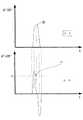
この実施例では、本方法は、図1乃至3を参照して説明し示した種々のステップに従う。図9では、時間tに依存した2次導関数d2i/dt2が、図3に既に示された繰り返しとして示される。図10に示すように、3次導関数d3i/dt3は、2次導関数d2i/dt2から生成される。3次導関数d3i/dt3のピークが現れ、その値が正であり且つ所与の閾値v1を上回る場合、制御信号sが生成される。信号sは、同様に、電気工具2の速度を低減するために使用される。In this embodiment, the method follows the various steps described and illustrated with reference to FIGS. In FIG. 9, the second derivative d2 i / dt2 as a function of time t is shown as a repetition already shown in FIG. As shown in FIG. 10, the third derivative d3 i / dt3 is generated from the second derivative d2 i / dt2 . If the peak of the third derivative d3 i / dt3 appears and its value is positive and exceeds a given threshold v1, a control signal s is generated. The signal s is likewise used to reduce the speed of the
当業者は、同様に、4次、5次若しくはより高いn次導関数を計測することにより制御信号sを生成することを知っている。それを結論付けることは容易であり、従って、出願人はここでは詳説しない。 Those skilled in the art also know to generate the control signal s by measuring the fourth, fifth or higher nth derivative. It is easy to conclude, and the applicant will not elaborate here.
図11に図示される回路に示すように、第2の微分器28の出力信号は、第3の微分器34に供給され、そこで、3次導関数d3i/dt3が形成される。第3の微分器34の出力信号のうち、正のパルスp1は、電子制御回路30に供給される。それは、制御信号sとされる。電子制御回路30により、モータ6におけるDC電流iの低減若しくは完全なゼロ化をも引き起こす。As shown in the circuit illustrated in FIG. 11, the output signal of the
同様に、注意すべきこととして、制御デバイス22を構成するすべての要素は、マイクロプロセッサにより置換されることができる。 Similarly, it should be noted that all elements comprising the
上述の第2実施例によれば、記憶及び処理ユニット32は、所定の導関数値q2を内部に記憶してもよい。若しくは、それは、処理のために複数のセットの所定の導関数値q1q2,q3,...及び閾値P1,P2,P3を含んでもよい。 According to the second embodiment described above, the storage and
図5乃至8で上述した手順及び保護装置は、同様に、スクリュー14のヘッドがボード16に到達したときに迅速で信頼性の高い反応が得られるという効果を有する。保護装置は、全て電子化される。 The procedure and the protective device described above in FIGS. 5 to 8 likewise have the effect that a quick and reliable reaction is obtained when the head of the
尚、1次導関数、2次導関数若しくはより高次の導関数は、数学で定義される導関数だけでなく、エンジニアリングのプラクティスの微分原理に基づく簡易な均等物でもある。例えば、1次導関数は、連続する時間間隔Δt間の電流変化Δiとして、即ちΔi/Δtとして表現されてもよい。エンジニアリングで容易に使用されるために、Δtは、Δt=10msのような、非常に小さい一定値であるべきである。従って、電流の際が連続的にチェックされる場合、1次導関数に対する考慮が等価的に実現されるはずである。同様に、2次及びn次(n≧3)に対する同様の均等物は、本発明の導関数の意味に含まれるべきである。 The first derivative, second derivative or higher order derivative is not only a mathematically defined derivative but also a simple equivalent based on the differential principle of engineering practice. For example, the first derivative may be expressed as a current change Δi between successive time intervals Δt, ie Δi / Δt. In order to be easily used in engineering, Δt should be a very small constant value, such as Δt = 10 ms. Thus, if the current is continuously checked, consideration for the first derivative should be equivalently realized. Similarly, similar equivalents for second order and nth order (n ≧ 3) should be included in the meaning of the derivatives of the present invention.
電気ドライバは、好ましい実施例として図示されているが、当然に、本発明の制御方法は、電気ドリル、電気レンチ等のような、他の動力工具で使用されてもよい。それは、当業者にとって上述の実施例により実現することは容易であるので、出願人は詳説しない。 Although an electric driver is illustrated as a preferred embodiment, it will be appreciated that the control method of the present invention may be used with other power tools such as an electric drill, electric wrench, and the like. It is easy for those skilled in the art to realize by the above-mentioned embodiments, and the applicant does not explain in detail.
2 電気ドライバ
4 作業組立体
6 電気モータ
8 ドリル
10 チャック
12 クラッチシステム
14 作業ヘッド/スクリュー
16 木のボード
18 電源
20 スイッチ
22 電子制御デバイス
24 電流センサ
26 第1微分器
28 第2微分器
30 電子制御回路
32 処理ユニット
A 第1位置/第1部位
B 第3位置/第2部位
K 第2位置/第3部位/膝部
A1 第1の電流曲線
A2 第2の電流曲線
a1 第1の曲線
a2 第2の曲線
i 電流
i1 第1の電流値
i2 第2の電流値
i3 第3の電流値
P1 第1の閾値
P2 第2の閾値
P3 第3の閾値
p ピーク信号
q1 第1の所定の導関数値
q2 第2の所定の導関数値
q3 第3の所定の導関数値
s 制御信号
s1 第1の制御信号
s2 第2の制御信号
T1 所定の時点
t1 第1の時点
t2 第2の時点
v 所定の閾値2
Claims (17)
Translated fromJapanese所定の時点で前記電気工具に供給される電流を測定するステップと、
前記所定の時点で、前記測定した電流が所定の第1の閾値よりも低い場合に第1の所定の導関数値を、前記測定した電流が前記所定の第1の閾値よりも高い場合に前記第1の所定の導関数値よりも高い第2の所定の導関数値を選択するステップと、
時間に依存した前記電流の1次導関数を形成するステップと、
前記1次導関数が前記第1若しくは第2の所定の導関数値に到達したときに前記1次導関数から制御信号を生成するステップと、
前記制御信号に応答して前記電気工具の回転速度を変更するステップとを含む、
方法。A method of controlling an electric tool that is supplied with current to generate a rotational speed, comprising:
Measuring the current supplied to the electric tool at a predetermined time;
A first predetermined derivative value when the measured current is lower than a predetermined first threshold at the predetermined time point, and when the measured current is higher than the predetermined first threshold. Selecting a second predetermined derivative value that is higher than the first predetermined derivative value;
Forming a first derivative of the current as a function of time;
Generating a control signal from the first derivative when the first derivative reaches the first or second predetermined derivative value;
Changing the rotational speed of the electric tool in response to the control signal,
Method.
a)回転速度をドリルが得るように、ドリルを駆動するモータと、
b)前記モータに電流を供給する源と、
c)前記電流を測定するセンサと、
d)制御手段とを含み、
該制御手段は、
d1)時系列の前記電流の勾配の変動を検出し、
d2)所定の時点での前記電流の値に応じて第1若しくは第2の所定の導関数値を選択し、
d3)前記第1若しくは第2の所定の導関数値から制御信号を生成し、
d4)前記制御信号に応答して前記電気工具の回転速度を変更する、
電気工具。An electric tool,
a) a motor that drives the drill so that the drill obtains the rotational speed;
b) a source for supplying current to the motor;
c) a sensor for measuring the current;
d) control means,
The control means includes
d1) detecting a variation in the gradient of the current in time series;
d2) selecting a first or second predetermined derivative value according to the value of the current at a predetermined time point;
d3) generating a control signal from the first or second predetermined derivative value;
d4) changing the rotational speed of the electric tool in response to the control signal;
Electric tool.
Applications Claiming Priority (2)
| Application Number | Priority Date | Filing Date | Title |
|---|---|---|---|
| CN200710020155.1 | 2007-02-16 | ||
| CN 200710020155CN101247100B (en) | 2007-02-16 | 2007-02-16 | Electric tool control method and electric tool using the same |
Related Parent Applications (1)
| Application Number | Title | Priority Date | Filing Date |
|---|---|---|---|
| JP2009549761ADivisionJP2010517804A (en) | 2007-02-16 | 2008-02-13 | Electric tool control method and electric tool for executing the same |
Publications (1)
| Publication Number | Publication Date |
|---|---|
| JP2013176840Atrue JP2013176840A (en) | 2013-09-09 |
Family
ID=39709629
Family Applications (3)
| Application Number | Title | Priority Date | Filing Date |
|---|---|---|---|
| JP2009549761APendingJP2010517804A (en) | 2007-02-16 | 2008-02-13 | Electric tool control method and electric tool for executing the same |
| JP2013099916APendingJP2013176840A (en) | 2007-02-16 | 2013-05-10 | Control method for electrical tool and electrical tool executing the same |
| JP2014217281APendingJP2015027733A (en) | 2007-02-16 | 2014-10-24 | Method for controlling electric tool and electric tool for executing the same |
Family Applications Before (1)
| Application Number | Title | Priority Date | Filing Date |
|---|---|---|---|
| JP2009549761APendingJP2010517804A (en) | 2007-02-16 | 2008-02-13 | Electric tool control method and electric tool for executing the same |
Family Applications After (1)
| Application Number | Title | Priority Date | Filing Date |
|---|---|---|---|
| JP2014217281APendingJP2015027733A (en) | 2007-02-16 | 2014-10-24 | Method for controlling electric tool and electric tool for executing the same |
Country Status (6)
| Country | Link |
|---|---|
| US (1) | US8881842B2 (en) |
| EP (1) | EP2128734B1 (en) |
| JP (3) | JP2010517804A (en) |
| CN (1) | CN101247100B (en) |
| TW (1) | TW200838101A (en) |
| WO (1) | WO2008101408A1 (en) |
Cited By (1)
| Publication number | Priority date | Publication date | Assignee | Title |
|---|---|---|---|---|
| US9162331B2 (en) | 2009-01-04 | 2015-10-20 | Positec Power Tools (Suzhou) Co. Ltd. | Electric tool and controlling method thereof |
Families Citing this family (55)
| Publication number | Priority date | Publication date | Assignee | Title |
|---|---|---|---|---|
| US8269612B2 (en) | 2008-07-10 | 2012-09-18 | Black & Decker Inc. | Communication protocol for remotely controlled laser devices |
| CN104485860B (en)* | 2009-01-04 | 2017-08-22 | 苏州宝时得电动工具有限公司 | The control method of electric tool and the electric tool for performing the control method |
| CN101786267A (en)* | 2009-01-22 | 2010-07-28 | 苏州宝时得电动工具有限公司 | Electric tool |
| CN101786178B (en)* | 2009-01-22 | 2012-10-03 | 苏州宝时得电动工具有限公司 | Electric tool |
| CN101941192B (en)* | 2009-07-10 | 2012-11-21 | 苏州宝时得电动工具有限公司 | Electric tool |
| JP5412249B2 (en)* | 2009-11-19 | 2014-02-12 | 株式会社マキタ | Hand tool |
| CN102695588A (en)* | 2009-12-17 | 2012-09-26 | 日东精工株式会社 | Threaded fastener tightening and loosening device |
| US8418778B2 (en)* | 2010-01-07 | 2013-04-16 | Black & Decker Inc. | Power screwdriver having rotary input control |
| US9950417B2 (en)* | 2010-03-31 | 2018-04-24 | Hitachi Koki Co., Ltd. | Power tool |
| DE102011122212B4 (en)* | 2010-12-29 | 2022-04-21 | Robert Bosch Gmbh | Battery-powered screwing system with reduced radio-transmitted data volume |
| WO2012175901A1 (en)* | 2011-06-20 | 2012-12-27 | Husqvarna Uk Limited | Speed control for power tools |
| JP6454151B2 (en)* | 2011-10-28 | 2019-01-16 | デカ・プロダクツ・リミテッド・パートナーシップ | Product extraction system with PWM control solenoid pump |
| CN103124065B (en)* | 2011-11-18 | 2016-03-16 | 苏州宝时得电动工具有限公司 | Electric tool and control method thereof |
| US9908182B2 (en) | 2012-01-30 | 2018-03-06 | Black & Decker Inc. | Remote programming of a power tool |
| CN103368480B (en)* | 2012-03-31 | 2016-11-16 | 苏州宝时得电动工具有限公司 | Electric hand tool and control method thereof |
| CN103368483B (en)* | 2012-03-31 | 2016-02-17 | 苏州宝时得电动工具有限公司 | Electric hand tool and control method thereof |
| CN103386665B (en)* | 2012-05-07 | 2015-07-01 | 苏州宝时得电动工具有限公司 | Control method of electric tool and electric tool used for executing control method |
| US20130327552A1 (en)* | 2012-06-08 | 2013-12-12 | Black & Decker Inc. | Power tool having multiple operating modes |
| US8919456B2 (en)* | 2012-06-08 | 2014-12-30 | Black & Decker Inc. | Fastener setting algorithm for drill driver |
| CN103567938B (en)* | 2012-07-19 | 2015-10-28 | 盈佳科技(长春)有限公司 | A kind of adjustable lock screw height electric screw driver and method of work thereof |
| CN104339299B (en)* | 2013-08-06 | 2019-04-19 | 苏州宝时得电动工具有限公司 | A kind of electric tool |
| DE102013224759A1 (en)* | 2013-12-03 | 2015-06-03 | Robert Bosch Gmbh | Machine tool device |
| CN105929788A (en)* | 2014-09-02 | 2016-09-07 | 苏州宝时得电动工具有限公司 | Electric tool control method and system, and electric tool |
| US10654153B2 (en)* | 2015-01-30 | 2020-05-19 | Koki Holdings Co., Ltd. | Impact tool |
| US10406662B2 (en) | 2015-02-27 | 2019-09-10 | Black & Decker Inc. | Impact tool with control mode |
| CN106142023A (en)* | 2015-04-24 | 2016-11-23 | 苏州宝时得电动工具有限公司 | Electric tool and electric tool remote information collection device, system and method |
| KR102074052B1 (en)* | 2015-06-02 | 2020-02-05 | 밀워키 일렉트릭 툴 코포레이션 | Multi-speed power tools with electronic clutch |
| CN106346403A (en)* | 2015-07-14 | 2017-01-25 | 苏州宝时得电动工具有限公司 | Electric tool and electric tool control method |
| CN106483846B (en)* | 2015-09-01 | 2019-12-13 | 苏州宝时得电动工具有限公司 | Control method of electric tool and electric tool for executing control method |
| WO2017106303A1 (en) | 2015-12-14 | 2017-06-22 | Milw A Ukee Electric Tool Corporation | Overload detection in a power tool |
| CN105500264A (en)* | 2015-12-31 | 2016-04-20 | 宁波中旺工具有限公司 | Electric screwdriver and control method thereof |
| CN108778651B (en) | 2016-02-03 | 2021-06-18 | 米沃奇电动工具公司 | System and method for configuring a reciprocating saw |
| JP6590262B2 (en)* | 2017-01-13 | 2019-10-16 | パナソニックIpマネジメント株式会社 | Electric tool |
| US10483901B2 (en)* | 2017-07-10 | 2019-11-19 | Newfrey Llc | System and method for installation and verification of fasteners |
| US11097405B2 (en) | 2017-07-31 | 2021-08-24 | Ingersoll-Rand Industrial U.S., Inc. | Impact tool angular velocity measurement system |
| DE102017122069A1 (en) | 2017-09-22 | 2019-03-28 | Illinois Tool Works Inc. | Orbital welding device with improved safety and reduced failure probability |
| WO2019168759A1 (en) | 2018-02-28 | 2019-09-06 | Milwaukee Electric Tool Corporation | Simulated bog-down system and method for power tools |
| US11338405B2 (en) | 2018-02-28 | 2022-05-24 | Milwaukee Electric Tool Corporation | Eco-indicator for power tool |
| CN213646135U (en) | 2018-03-16 | 2021-07-09 | 米沃奇电动工具公司 | Blade clamp and reciprocating electric tool |
| US11014176B2 (en) | 2018-04-03 | 2021-05-25 | Milwaukee Electric Tool Corporation | Jigsaw |
| USD887806S1 (en) | 2018-04-03 | 2020-06-23 | Milwaukee Electric Tool Corporation | Jigsaw |
| CN108994769B (en)* | 2018-08-21 | 2021-01-15 | 凡己科技(苏州)有限公司 | A electronic bottle opener for improving copper bar installation accuracy |
| CN111185874B (en)* | 2018-11-15 | 2023-09-08 | 南京泉峰科技有限公司 | Impact screw driver, rotary impact tool and control method thereof |
| JP7210291B2 (en) | 2019-01-10 | 2023-01-23 | 株式会社マキタ | electric driver drill |
| CN111775118B (en)* | 2019-04-04 | 2023-06-20 | 南京泉峰科技有限公司 | Intelligent electric tool, system and control method thereof |
| KR102653160B1 (en) | 2019-05-17 | 2024-04-01 | 엘지전자 주식회사 | Method of controlling laundry treating apparatus |
| US11673240B2 (en) | 2019-08-06 | 2023-06-13 | Makita Corporation | Driver-drill |
| KR20210027894A (en) | 2019-09-03 | 2021-03-11 | 삼성전자주식회사 | Driver assistant system, electronic device and operation method thereof |
| DE102019215415A1 (en) | 2019-10-09 | 2021-04-15 | Robert Bosch Gmbh | Method for teaching in application shutdowns with the help of finding characteristic signal forms when operating a handheld power tool |
| DE102019215417A1 (en)* | 2019-10-09 | 2021-04-15 | Robert Bosch Gmbh | Method for operating a hand machine tool |
| US11919135B2 (en) | 2020-07-06 | 2024-03-05 | Milwaukee Electric Tool Corporation | Automatic ramp load sense for power tools |
| US12226884B2 (en) | 2021-11-29 | 2025-02-18 | Ingersoll-Rand Industrial U.S., Inc. | High resolution anvil angle sensor |
| US12434371B2 (en) | 2022-03-23 | 2025-10-07 | Milwaukee Electric Tool Corporation | Electronic clutch for power tools |
| CN116803620A (en)* | 2022-03-23 | 2023-09-26 | 米沃奇电动工具公司 | Electronic clutch for power tool |
| WO2024229548A1 (en) | 2023-05-05 | 2024-11-14 | New World Technologies Inc. | A torque tool with fault protection and a method of operating the same |
Citations (4)
| Publication number | Priority date | Publication date | Assignee | Title |
|---|---|---|---|---|
| JPS5633255A (en)* | 1979-05-01 | 1981-04-03 | Black & Decker Inc | Method and device for controlling recoil preventive power tool |
| JPS57114373A (en)* | 1980-12-29 | 1982-07-16 | Matsushita Electric Works Ltd | Automatic torque setting circuit for motor driver |
| JPH08141928A (en)* | 1994-11-16 | 1996-06-04 | Tonichi Seisakusho:Kk | Screw fastening control signal detecting method |
| JPH09304681A (en)* | 1996-03-15 | 1997-11-28 | Asahi Optical Co Ltd | Automatic focusing device for telephoto optics |
Family Cites Families (36)
| Publication number | Priority date | Publication date | Assignee | Title |
|---|---|---|---|---|
| CA1006606A (en)* | 1972-05-22 | 1977-03-08 | Katsuyuki Totsu | Motor-driven screw driver with automatic stopping means |
| US4013895A (en) | 1972-08-28 | 1977-03-22 | Mitsubishi Denki Kabushiki Kaisha | Clamping tool and method |
| JPS5722702B2 (en)* | 1973-12-11 | 1982-05-14 | ||
| JPS6043266B2 (en) | 1979-11-12 | 1985-09-27 | ファナック株式会社 | Motor drive control method |
| JPS5854954B2 (en)* | 1979-12-17 | 1983-12-07 | 芝浦メカトロニクス株式会社 | bolt tightening machine |
| JPS5946747B2 (en) | 1979-12-20 | 1984-11-14 | 芝浦メカトロニクス株式会社 | bolt tightening machine |
| FR2522144A1 (en)* | 1982-02-24 | 1983-08-26 | Vallourec | METHOD AND DEVICE FOR ENSURING THE CORRECT VISE OF A TUBULAR JOINT HAVING A SCREW LIMITATION BIT |
| DE3500714C1 (en) | 1985-01-11 | 1988-12-22 | Kipfelsberger, Albert, 8070 Ingolstadt | Power wrench with torque limitation |
| DE3634895A1 (en) | 1986-10-14 | 1988-04-21 | Egm Entwicklung Montage | METHOD AND DEVICE FOR TIGHTENING A SCREW CONNECTION |
| DE3634896A1 (en) | 1986-10-14 | 1988-04-21 | Egm Entwicklung Montage | METHOD AND DEVICE FOR TIGHTENING A SCREW CONNECTION |
| DE3710512A1 (en) | 1987-03-30 | 1988-10-20 | Bosch Gmbh Robert | SCREW METHOD AND SCREWDRIVER FOR THE AUTOMATIC TIGHTENING OF SCREWS AND / OR NUTS |
| JPH0332531A (en) | 1989-06-28 | 1991-02-13 | Mantoku:Kk | Screw tightening machine |
| US5410229A (en)* | 1992-07-31 | 1995-04-25 | Black & Decker Inc. | Motor speed control circuit with electronic clutch |
| GB9320181D0 (en) | 1993-09-30 | 1993-11-17 | Black & Decker Inc | Improvements in and relating to power tools |
| JPH0899270A (en)* | 1994-09-30 | 1996-04-16 | Nikko Eng Kk | Screw fastening method and device |
| US6479958B1 (en) | 1995-01-06 | 2002-11-12 | Black & Decker Inc. | Anti-kickback and breakthrough torque control for power tool |
| DE19620782A1 (en)* | 1995-06-03 | 1996-12-05 | Volkswagen Ag | Screw connection prodn. method by turning screw element using electric driven screwdriver |
| JP2936506B2 (en) | 1995-07-11 | 1999-08-23 | クワンタイシステムス株式会社 | Optimal time bolt tightening method |
| JP3473203B2 (en)* | 1995-07-27 | 2003-12-02 | 井関農機株式会社 | Fruit harvesting hand |
| US6581696B2 (en) | 1998-12-03 | 2003-06-24 | Chicago Pneumatic Tool Company | Processes of determining torque output and controlling power impact tools using a torque transducer |
| JP3231027B2 (en) | 1999-09-10 | 2001-11-19 | 義昭 垣野 | Numerical control device for NC machine tools |
| JP2002096271A (en)* | 2000-09-14 | 2002-04-02 | Uryu Seisaku Ltd | Drive control method of hydraulic torque wrench driven by electric motor |
| JP2003136419A (en)* | 2001-10-26 | 2003-05-14 | Matsushita Electric Works Ltd | Rotary tool |
| AUPS195102A0 (en)* | 2002-04-24 | 2002-05-30 | Flinders University Of South Australia, The | Adaptive apparatus for driving a threaded device into material such as biological tissue |
| US7091683B1 (en) | 2003-10-24 | 2006-08-15 | Intelligent Automation Design, Llc | Method of monitoring and controlling the seating of screws to the optimum point of grip independent of screw size and material density |
| US7410006B2 (en)* | 2004-10-20 | 2008-08-12 | Black & Decker Inc. | Power tool anti-kickback system with rotational rate sensor |
| TW200706304A (en) | 2005-08-08 | 2007-02-16 | Rexon Ind Corp Ltd | Transmission-controlling device |
| US20060152179A1 (en) | 2004-12-13 | 2006-07-13 | Rexon Industrial Corporation Ltd. | Transmission-controlling device |
| CN2762964Y (en) | 2005-01-10 | 2006-03-08 | 南京德朔实业有限公司 | Electric tool power supplied by battery |
| JP4211744B2 (en) | 2005-02-23 | 2009-01-21 | パナソニック電工株式会社 | Impact tightening tool |
| US7314097B2 (en) | 2005-02-24 | 2008-01-01 | Black & Decker Inc. | Hammer drill with a mode changeover mechanism |
| CN100475449C (en) | 2005-11-08 | 2009-04-08 | 车王电子股份有限公司 | electrical tools |
| CN101499763B (en) | 2008-02-03 | 2011-06-29 | 苏州宝时得电动工具有限公司 | Controlling method for electric tool and electric tool executing the controlling method |
| CN101771379B (en) | 2009-01-04 | 2015-02-04 | 苏州宝时得电动工具有限公司 | Control method of electric tool and electric tool implementing the control method |
| CN201405335Y (en) | 2009-01-16 | 2010-02-17 | 苏州宝时得电动工具有限公司 | Electric tool |
| CN201405095Y (en) | 2009-02-11 | 2010-02-17 | 苏州宝时得电动工具有限公司 | Electric tool |
- 2007
- 2007-02-16CNCN 200710020155patent/CN101247100B/ennot_activeExpired - Fee Related
- 2007-03-13TWTW96108613Apatent/TW200838101A/ennot_activeIP Right Cessation
- 2008
- 2008-02-13USUS12/527,018patent/US8881842B2/ennot_activeExpired - Fee Related
- 2008-02-13EPEP08706520.7Apatent/EP2128734B1/ennot_activeNot-in-force
- 2008-02-13JPJP2009549761Apatent/JP2010517804A/enactivePending
- 2008-02-13WOPCT/CN2008/000345patent/WO2008101408A1/enactiveApplication Filing
- 2013
- 2013-05-10JPJP2013099916Apatent/JP2013176840A/enactivePending
- 2014
- 2014-10-24JPJP2014217281Apatent/JP2015027733A/enactivePending
Patent Citations (4)
| Publication number | Priority date | Publication date | Assignee | Title |
|---|---|---|---|---|
| JPS5633255A (en)* | 1979-05-01 | 1981-04-03 | Black & Decker Inc | Method and device for controlling recoil preventive power tool |
| JPS57114373A (en)* | 1980-12-29 | 1982-07-16 | Matsushita Electric Works Ltd | Automatic torque setting circuit for motor driver |
| JPH08141928A (en)* | 1994-11-16 | 1996-06-04 | Tonichi Seisakusho:Kk | Screw fastening control signal detecting method |
| JPH09304681A (en)* | 1996-03-15 | 1997-11-28 | Asahi Optical Co Ltd | Automatic focusing device for telephoto optics |
Cited By (1)
| Publication number | Priority date | Publication date | Assignee | Title |
|---|---|---|---|---|
| US9162331B2 (en) | 2009-01-04 | 2015-10-20 | Positec Power Tools (Suzhou) Co. Ltd. | Electric tool and controlling method thereof |
Also Published As
| Publication number | Publication date |
|---|---|
| TW200838101A (en) | 2008-09-16 |
| JP2015027733A (en) | 2015-02-12 |
| CN101247100B (en) | 2012-01-25 |
| TWI335703B (en) | 2011-01-01 |
| EP2128734A1 (en) | 2009-12-02 |
| EP2128734B1 (en) | 2015-04-15 |
| CN101247100A (en) | 2008-08-20 |
| WO2008101408A1 (en) | 2008-08-28 |
| EP2128734A4 (en) | 2013-11-13 |
| US20100089600A1 (en) | 2010-04-15 |
| US8881842B2 (en) | 2014-11-11 |
| JP2010517804A (en) | 2010-05-27 |
Similar Documents
| Publication | Publication Date | Title |
|---|---|---|
| JP2013176840A (en) | Control method for electrical tool and electrical tool executing the same | |
| EP2380704B1 (en) | Control method for power tool and power tool executing control method | |
| CN101499763B (en) | Controlling method for electric tool and electric tool executing the controlling method | |
| US11192232B2 (en) | Power tool with anti-kickback control system | |
| JP6406792B2 (en) | Method and control device for controlling electric motor of electric tool | |
| CN201152938Y (en) | Control system suitable for using in power tool | |
| US6971454B2 (en) | Pulsed rotation screw removal and insertion device | |
| EP2937187B1 (en) | Power tool with control system | |
| US20190047133A1 (en) | Application-optimized deactivation behavior of an electronic slipping clutch | |
| CN106483846B (en) | Control method of electric tool and electric tool for executing control method | |
| CN105215953B (en) | Electric tool | |
| CN103386665B (en) | Control method of electric tool and electric tool used for executing control method | |
| EP3302882B1 (en) | Power tools with user-selectable operational modes | |
| CN201159251Y (en) | Controller of power tool with slewing axis | |
| CN104485860B (en) | The control method of electric tool and the electric tool for performing the control method | |
| JP7357278B2 (en) | Power tools, power tool control methods and programs | |
| US20090190905A1 (en) | Regulator Circuit for an Electric Motor, Provided with a Microprocessor | |
| KR20180010401A (en) | Electronic Tool having Hitting Function and Hitting Method of the Same | |
| CN109995307A (en) | The control method of electric tool and the electric tool for executing the control method | |
| JP6913870B2 (en) | Impact rotary tool | |
| CN116710234A (en) | Electric tool, control method and program for electric tool |
Legal Events
| Date | Code | Title | Description |
|---|---|---|---|
| A521 | Written amendment | Free format text:JAPANESE INTERMEDIATE CODE: A523 Effective date:20130529 | |
| A977 | Report on retrieval | Free format text:JAPANESE INTERMEDIATE CODE: A971007 Effective date:20140314 | |
| A131 | Notification of reasons for refusal | Free format text:JAPANESE INTERMEDIATE CODE: A131 Effective date:20140408 | |
| A601 | Written request for extension of time | Free format text:JAPANESE INTERMEDIATE CODE: A601 Effective date:20140602 | |
| A602 | Written permission of extension of time | Free format text:JAPANESE INTERMEDIATE CODE: A602 Effective date:20140605 | |
| A02 | Decision of refusal | Free format text:JAPANESE INTERMEDIATE CODE: A02 Effective date:20141104 |