JP2013171279A - Imaging apparatus - Google Patents
Imaging apparatusDownload PDFInfo
- Publication number
- JP2013171279A JP2013171279AJP2012037284AJP2012037284AJP2013171279AJP 2013171279 AJP2013171279 AJP 2013171279AJP 2012037284 AJP2012037284 AJP 2012037284AJP 2012037284 AJP2012037284 AJP 2012037284AJP 2013171279 AJP2013171279 AJP 2013171279A
- Authority
- JP
- Japan
- Prior art keywords
- wobbling
- imaging apparatus
- sound
- focusing lens
- period
- Prior art date
- Legal status (The legal status is an assumption and is not a legal conclusion. Google has not performed a legal analysis and makes no representation as to the accuracy of the status listed.)
- Granted
Links
Images


Landscapes
- Focusing (AREA)
- Automatic Focus Adjustment (AREA)
- Studio Devices (AREA)
Abstract
Translated fromJapaneseDescription
Translated fromJapanese本発明は、撮像装置に関するものである。 The present invention relates to an imaging apparatus.
一眼レフカメラタイプのデジタルカメラ等の撮像装置において、動画撮影機能を有するものがある。動画撮影では、被写体の動きに合わせて合焦レンズの位置を追従させることが望まれる。このため、合焦レンズを前後に細かく移動させ、画像のコントラストの変化から合焦状態を検出して、被写体への合焦を維持する、いわゆるウォブリング動作が行われている(特許文献1参照)。 Some imaging apparatuses such as a single-lens reflex camera type digital camera have a moving image shooting function. In moving image shooting, it is desirable to follow the position of the focusing lens in accordance with the movement of the subject. For this reason, a so-called wobbling operation is performed in which the focusing lens is finely moved back and forth, the focus state is detected from the change in the contrast of the image, and the focus on the subject is maintained (see Patent Document 1). .
ウォブリング動作の際、合焦レンズの駆動源は駆動/停止を繰り返す。駆動源は、この駆動/停止の際に作動音を発生するため、この作動音がマイクに伝達して記録(録音)され、耳障りとなる。 During the wobbling operation, the driving source of the focusing lens repeats driving / stopping. Since the drive source generates an operation sound at the time of driving / stopping, the operation sound is transmitted to the microphone and recorded (recorded), which becomes harsh.
本発明の課題は、ウォブリングによる駆動音の発生頻度を調整可能な撮像装置を提供することである。 The subject of this invention is providing the imaging device which can adjust the generation frequency of the drive sound by wobbling.
本発明は、以下のような解決手段により前記課題を解決する。なお、理解を容易にするために、本発明の実施形態に対応する符号を付して説明するが、これに限定されるものではない。 The present invention solves the above problems by the following means. In addition, in order to make an understanding easy, although the code | symbol corresponding to embodiment of this invention is attached | subjected and demonstrated, it is not limited to this.
請求項1に記載の発明は、動画撮影可能な撮像装置(1)であって、合焦レンズ(21)と、合焦レンズ(21)を駆動する駆動部(30)と、動画撮影中に、前記合焦レンズ(21)をウォブリング動作させる制御部(12)と、を備え、前記制御部(12)は、前記ウォブリング動作の周期を変更可能であること、を特徴とする撮像装置(1)である。
請求項2に記載の発明は、請求項1に記載の撮像装置(1)であって、動画撮影中に音声を集音する集音部(13)を備え、前記制御部(12)は、前記集音部(13)により集音された音声レベルによって、前記ウォブリング動作の周期を変更すること、を特徴とする撮像装置(1)である。
請求項3に記載の発明は、請求項1または2に記載の撮像装置(1)であって、前記撮像装置(1)は、静音優先モードとオートフォーカス速度優先モードとのいずれかを選択可能な選択部(15)を備え、前記制御部(12)は、前記静音優先モードが選択されている場合に前記周期を変更すること、を特徴とする撮像装置(1)である。
請求項4に記載の発明は、請求項1〜3のいずれか1項に記載の撮像装置(1)であって、前記制御部(12)は、該撮像装置(1)の被写界深度を演算可能で、前記被写界深度に応じて、前記周期を変更すること、を特徴とする撮像装置(1)である。
なお、符号を付して説明した構成は、適宜改良してもよく、また、少なくとも一部を他の構成物に代替してもよい。The invention described in claim 1 is an image pickup apparatus (1) capable of shooting a moving image, wherein the focusing lens (21), a drive unit (30) for driving the focusing lens (21), and moving image shooting A control unit (12) for wobbling the focusing lens (21), and the control unit (12) is capable of changing a cycle of the wobbling operation. ).
Invention of Claim 2 is an imaging device (1) of Claim 1, Comprising: The sound collection part (13) which collects sound during video recording is provided, The said control part (12) The imaging apparatus (1), wherein the period of the wobbling operation is changed according to the sound level collected by the sound collection unit (13).
Invention of Claim 3 is an imaging device (1) of Claim 1 or 2, Comprising: The said imaging device (1) can select either a silent priority mode or an autofocus speed priority mode The image pickup apparatus (1) includes a selection unit (15), and the control unit (12) changes the cycle when the silent priority mode is selected.
Invention of Claim 4 is an imaging device (1) of any one of Claims 1-3, Comprising: The said control part (12) is the depth of field of this imaging device (1). The imaging apparatus (1) is characterized in that the period can be changed according to the depth of field.
Note that the configuration described with reference numerals may be modified as appropriate, and at least a part of the configuration may be replaced with another component.
本発明によれば、ウォブリングによる駆動音の発生頻度を調整可能な撮像装置を提供することができる。 ADVANTAGE OF THE INVENTION According to this invention, the imaging device which can adjust the generation frequency of the drive sound by wobbling can be provided.
以下、図面等を参照して、本発明の実施形態について説明する。
図1は、本発明における一実施形態のカメラ1を説明する概念図である。本実施形態におけるカメラ1は、動画撮影機能を有するカメラ1である。
カメラ1は、カメラボディ10と、レンズ鏡筒20とを備えている。レンズ鏡筒20は、カメラボディ10に着脱可能な交換レンズである。なお、本実施形態では、レンズ鏡筒20が交換可能な例を示したが、これに限らず、例えば、カメラボディとレンズ鏡筒が一体型のカメラであってもよい。Embodiments of the present invention will be described below with reference to the drawings.
FIG. 1 is a conceptual diagram illustrating a camera 1 according to an embodiment of the present invention. The camera 1 in this embodiment is a camera 1 having a moving image shooting function.
The camera 1 includes a
カメラボディ10は、撮像素子11、制御装置12、集音マイク13、記録部14、操作部15、表示部16、およびボディ側接点17を備えている。
撮像素子11は、レンズ鏡筒20を通過した被写体像を撮像する光電変換素子であり、被写体光を露光して電気的な画像信号に変換するCCDやCMOS等の素子である。
集音マイク13は、動画撮影時に、音声を集音するためのものである。
記録部14は、撮像された画像データ、録音データを記録するための媒体であり、SDカードやCFカード等が用いられる。The
The
The
The
操作部15は、撮影者が、撮影条件や再生条件の選択、静止画撮影モードと動画撮影モードとのいずれかの選択を行う部分である。さらに操作部15を介して撮影者は、後述するウォブリング動作のモードである静音優先モードと通常モード(AF優先モード)とのいずれかの選択が可能である。
表示部16は、カメラボディ10の背面に設けられ、撮像素子11で撮像した被写体像(再生画像やライブビュー画像)や操作に関連した情報(メニュー)などを表示する液晶ディスプレィである。
ボディ側接点17は、レンズ鏡筒20に設けられたレンズ側接点25と接続して、レンズ鏡筒20とカメラボディ10との通信を行う。The
The
The body-
制御装置12は、当該カメラ1全体を統括的に制御する制御部である。制御装置12は、被写界深度演算部12A、音声レベル判定部12B、1ウォブリング動作の周期を決定するウォブリング周期決定部12C、焦点調整情報を検出する焦点情報検出部12D、および超音波モータ30の駆動電力を形成する駆動回路12E等を備えている。 The
被写界深度演算部12Aは、レンズ鏡筒20の焦点距離、絞り値、撮影距離等より、被写界深度を求める。その情報はウォブリング周期決定部12Cによるウォブリングの周期Tの決定に用いられる。
音声レベル判定部12Bは、マイク13において集音された音声のレベルを判定する。The depth of
The sound
ウォブリング周期決定部12Cは、操作部15を通じて選択されたウォブリングモードと、被写界深度演算部12Aによって演算された被写界深度と、音声レベル判定部12Bによって判定された音声レベルと、によって、ウォブリング動作の1周期である周期Tを決定する。
なお、ウォブリングとは、動画撮像やプレビュー撮像時において、合焦レンズ21を常に動かし続けて被写体付近に常にフォーカスを合わせる動作である。The wobbling
Note that wobbling is an operation in which the focusing
焦点情報検出部12Dは、動画撮影時において、撮像素子11が撮像した画像のコントラストの変化から合焦状態の変化を検出する。
駆動回路12Eは、後述する超音波モータ30を駆動する駆動電力を形成する。駆動回路12Eは、その出力する駆動電力の周波数を変更することにより、超音波モータ30の速度を可変となっている。The focus
The
そして、制御装置12は、焦点情報検出部12Dによる焦点検出情報に基づいて駆動回路12Eを制御し、超音波モータ30を駆動して後述するレンズ鏡筒20における合焦レンズ21を移動させ、被写体の合焦状態を維持するように制御する。
この際、制御装置12は、ウォブリング周期決定部12Cによって決定された周期でウォブリング動作を行う。Then, the
At this time, the
レンズ鏡筒20は、合焦レンズ21、カム筒22、アイドルギア23、超音波モータ30、及びこれらを包囲する外筒24、ボディ側接点17に接続されるレンズ側接点25等を備えている。
本実施形態では、超音波モータ30は、カム筒22と外筒24の間の円環状の隙間に配置されている。超音波モータ30は、カメラ1の合焦動作時に合焦レンズ21を駆動する駆動源である。超音波モータ30は、後述する出力ギア33が噛合するアイドルギア23を介してカム筒22を回転操作する。The
In the present embodiment, the
超音波モータ30は、振動子31と、振動子31に圧接配置された回転体32と、回転体32に結合された出力ギア33と、を備えている。
振動子31は、弾性体31Aと、弾性体31Aに接合された圧電体31Bと、により構成されている。振動子31は、図示しないフレキシブルプリント基板を介して制御装置12(駆動回路12E)から所定の電圧および周波数の駆動信号が供給され、これによって圧電体31Bが伸縮して弾性体31Aの駆動面に進行波を生ずる。The
The
そして、超音波モータ30は、振動子31の進行波によって回転体32が回転駆動され、出力ギア33が回転力を出力する。回転体32(出力ギア33)の速度(回転数)は、駆動信号の周波数に応じて変化する。つまり、超音波モータ30は、制御装置12による駆動回路12Eの駆動信号の周波数制御によって、回転数が制御されるようになっている。 In the
カム筒22は、超音波モータ30によって回転操作されると、外筒24内を光軸OAと平行する方向(Z軸方向)に移動可能に設けられている。
合焦レンズ21は、カム筒22に保持されている。そして、超音波モータ30の駆動によるカム筒22の移動によって、光軸OA方向に移動して焦点調節を行う。
なお、レンズ鏡筒20は、合焦レンズ21の他に、図示しないが複数のレンズ群を備えている。The
The focusing
In addition to the focusing
そして、カメラ1は、合焦レンズ21とレンズ鏡筒20内に設けられた図示しないレンズ群とによって、撮像素子11の撮像面に被写体像が結像される。撮像素子11は、結像された被写体像を電気信号に変換する。その電気信号は、A/D変換されて、画像データとされる。これらカメラ1における撮影に係る一連の動作は、制御装置12によって制御される。 In the camera 1, a subject image is formed on the imaging surface of the
ここで、前述したように、カメラ1は、動画撮影機能を有している。動画撮影時には、制御装置12は合焦レンズ21にウォブリング動作を行わせる。すなわち、動画撮影時において、制御装置12は、合焦レンズ21を前後に細かく移動させ、撮像素子11が撮像した画像のコントラストの変化に伴って焦点情報検出部12Dが検出した合焦状態の変化情報に基づいて、駆動回路12Eを制御して合焦調整を行う。 Here, as described above, the camera 1 has a moving image shooting function. At the time of moving image shooting, the
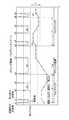
図2は、カメラのウォブリング動作を示すイメージ図である。
たとえば、カメラが動画モードに切り替えられると、図中のウォブリング1の動作が開始される。ウォブリングは、超音波モータ30によりフォーカスレンズ群5の光軸前方と後方への微動を行う動作である。ウォブリングは最低1サイクル行う。なお、図2においては1サイクルの例を示すが、実際には3〜5回/sec程度行う。ウォブリングの1サイクルとは、超音波モータ30の一方向への駆動、停止、逆方向への移動、停止(次の一方向への駆動まで)を含む、図中Tで示す期間である。FIG. 2 is an image diagram showing the wobbling operation of the camera.
For example, when the camera is switched to the moving image mode, the operation of wobbling 1 in the figure is started. The wobbling is an operation in which the
ウォブリング1が終了すると、撮像素子3のボケの程度に応じて、フォーカス範囲(方向と距離)Fを算出する。
そして、図2の期間Tafに示すように、超音波モータ30によって、フォーカスレンズ群5をフォーカス位置まで駆動する。When wobbling 1 is completed, a focus range (direction and distance) F is calculated according to the degree of blur of the image sensor 3.
Then, as shown in a period Taf in FIG. 2, the focus lens group 5 is driven to the focus position by the
その後、さらに、次のウォブリング2が行われる。ウォブリング2は、焦点が合っているか否かの確認のために行うものであり、動画撮影中は、被写体を追いかけるので、フォーカス範囲F内に合焦点がある限り、ウォブリングは連続して行われる。この際のウォブリング2の周期もウォブリング1と同様のTである。 Thereafter, the next wobbling 2 is further performed. The wobbling 2 is performed to check whether or not the focus is in focus, and the subject is chased during moving image shooting. Therefore, as long as the focus is within the focus range F, the wobbling is continuously performed. The period of wobbling 2 at this time is also the same as that of wobbling 1.
このように超音波モータ30が駆動すると、起動時の突発音a(a1〜a6),駆動音b(b1〜b6),停止時の突発音c(c1〜c6)が発生する。
起動時又は停止時の突発音a,cは、電流の流れる又は切れることにより、発生する音であり、駆動音bは、超音波モータ30が回転しているときの振動子31と回転体32の摺動音やベアリングの回転するメカ的な音である。なお、a5,b5,c5は、反転時の音である。
超音波モータ30の起動時の突発音a,駆動音b,停止時の突発音cを含んだ動画撮影時の音は、集音マイク13で集音される。1ウォブリング動作の周期Tについて突発音aが2回,駆動音bが1回,停止時の突発音cが2回含まれる。When the
The sudden sounds a and c at the time of starting or stopping are sounds generated when current flows or is cut off, and the driving sound b is a
Sounds during moving image shooting including a sudden sound a, a driving sound b when the
以下、本実施形態の動作について説明する。
本実施形態においては、操作部15において、撮影者が、AF優先モードか、静音優先モードのいずれかを選択可能となっている。
AF優先モードとは、デフォルトモードであり、合焦速度を優先し、マイク13の集音レベルによらず、1ウォブリング動作の周期Tを一定(T0)とするモードである。
静音優先モードとは、撮影者が選択によりAF優先モードから変更可能なモードである。マイク13の集音レベルに応じて、集音レベルが低いほど(静かなほど)、1ウォブリング動作の周期Tを長くするものである。Hereinafter, the operation of this embodiment will be described.
In the present embodiment, the photographer can select either the AF priority mode or the silent priority mode on the
The AF priority mode is a default mode in which priority is given to the focusing speed, and the period T of one wobbling operation is constant (T0) regardless of the sound collection level of the
The silent priority mode is a mode in which the photographer can change from the AF priority mode by selection. In accordance with the sound collection level of the
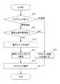
図3は本実施形態の動作を示すフローチャートである。
動画がスタートすると、制御装置12は、カメラ1の現在のモードを判断する(ステップS11)。
AF優先モードのときは、S16へ進む。静音優先モードのときは、被写界深度を所定の閾値と比較する(ステップS12)。
被写界深度が閾値より小さい場合(S12,NO)、すなわち被写界深度が浅いときは、合焦レンズ21が合焦位置からわずかにずれても、ぼけが目立つ状態となる。したがって、ウォブリング動作をこまめに行い、合焦状態を頻繁に確認することが必要である。このため、1ウォブリング動作の周期の変更は行わず、S16へ進みデフォルト設定の周期T0でウォブリングを行う(ステップS15)。FIG. 3 is a flowchart showing the operation of this embodiment.
When the moving image starts, the
If the AF priority mode is selected, the process proceeds to S16. In the silent priority mode, the depth of field is compared with a predetermined threshold (step S12).
When the depth of field is smaller than the threshold (S12, NO), that is, when the depth of field is shallow, even if the focusing
被写界深度が閾値以上の場合(S12,YES)、すなわち被写界深度が深いので、合焦レンズ21が合焦位置からわずかにずれていても、ぼけは比較的目立たない。したがって、1ウォブリングの周期を長くすることが可能であるので、次のステップS13へ進む。
S13では、マイク13より集音された音声レベルSの判断を、音声レベル判定部12Bで行う。When the depth of field is equal to or greater than the threshold (S12, YES), that is, the depth of field is deep, even if the focusing
In S13, the audio
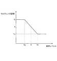
図4は、音声レベルSと、1ウォブリング動作の周期Tとの関係を示したものである。S14では、S13で判定された音声レベルSに基づいて1ウォブリング動作の周期Tを決定する。
図示するように、音声レベルSが低いとき(Sq:静かなシーン)には、ウォブリング動作の周期Tを長くし(Tl)、音声レベルSが高い(Sn:騒々しいシーン)では、ウォブリング動作の周期Tを短くする(T0)。FIG. 4 shows the relationship between the audio level S and the period T of one wobbling operation. In S14, the period T of one wobbling operation is determined based on the sound level S determined in S13.
As shown in the figure, when the audio level S is low (Sq: quiet scene), the period T of the wobbling operation is lengthened (Tl), and when the audio level S is high (Sn: noisy scene), the wobbling operation is performed. Is shortened (T0).
ここで、本実施形態では、ウォブリング動作の周期TはT0≦T≦Tlである。Tlはウォブリング動作として機能しうる最長時間であり、T0は、本実施形態においてデフォルトの周期T0である。
そしてS15において決定された周期Tでウォブリング動作を行う。Here, in the present embodiment, the period T of the wobbling operation is T0 ≦ T ≦ Tl. Tl is the longest time that can function as a wobbling operation, and T0 is the default period T0 in this embodiment.
Then, the wobbling operation is performed with the period T determined in S15.
図5は、ウォブリングサイクルTが変更された場合と、AF優先モードの場合のデフォルト周期T0の場合との、ウォブリング動作を示すイメージ図である。
図中点線で示すグラフNはウォブリングの周期がT0の場合であり、実線で示すグラフQはウォブリングの周期がTと長くなった場合である。FIG. 5 is an image diagram showing the wobbling operation when the wobbling cycle T is changed and when the default period T0 is in the AF priority mode.
A graph N indicated by a dotted line in the figure is when the wobbling period is T0, and a graph Q indicated by a solid line is when the wobbling period is as long as T.
このように1ウォブリング動作の周期がT0からTに変更されて長くなると、超音波モータ30の回転速度が遅くなる。すなわち、単位時間当たりの起動音発生回数が減少する。たとえば図5に示す時間tの区間について、AF優先モード(点線N)の場合、駆動音は9回発生するが、静音優先モード(実線Q)の場合5回となる。これによって単位時間当たりのノイズが減少し、静音化が図られる。 As described above, when the cycle of one wobbling operation is changed from T0 to T and becomes longer, the rotational speed of the
(変形形態)
以上、説明した実施形態に限定されることなく、以下に示すような種々の変形や変更が可能であり、それらも本発明の範囲内である。
(1)本実施形態では、被写界深度を所定の閾値以上かどうかで、1ウォブリングの周期Tを変更するかどうかを判定しているが、これに限定されない。たとえば、被写界深度によって、図4のグラフの傾きを変えても良い。たとえば、被写界深度が浅いとき、Tlを小さくし、図4の傾きの絶対値を小さくし、被写界深度が深いときはTlを大きくし、図4の傾きの絶対値が大きくすることができる。(Deformation)
The present invention is not limited to the above-described embodiment, and various modifications and changes as described below are possible, and these are also within the scope of the present invention.
(1) In this embodiment, it is determined whether or not to change the period T of one wobbling depending on whether or not the depth of field is equal to or greater than a predetermined threshold, but the present invention is not limited to this. For example, the inclination of the graph of FIG. 4 may be changed according to the depth of field. For example, when the depth of field is shallow, Tl is decreased, and the absolute value of the inclination in FIG. 4 is decreased. When the depth of field is deep, Tl is increased, and the absolute value of the inclination in FIG. 4 is increased. Can do.
(2)本実施形態では、音声レベルによって、1ウォブリングの周期Tを線形に変化させる例について説明したが、本発明はこれに限定されない。たとえば図6に示すように、音声レベルSに応じて、1ウォブリングの周期Tを段階的に変化させても良い。(2) In the present embodiment, the example in which the period T of one wobbling is linearly changed according to the sound level has been described, but the present invention is not limited to this. For example, as shown in FIG. 6, the period T of 1 wobbling may be changed stepwise according to the audio level S.
(3)本実施形態では、デジタル一眼レフカメラについて説明したが、本発明はこれに限定されず、コンパクトカメラや携帯電話などにも適用可能である。
(4)超音波モータは、円環型の例で説明したが、小型の出力軸を持ったものでもよい。この場合には、固定筒のモールドに取り付ければよい。また、固定筒に穴を形成して、埋め込むようにしてもよい。(3) In the present embodiment, the digital single-lens reflex camera has been described. However, the present invention is not limited to this, and can be applied to a compact camera, a mobile phone, and the like.
(4) Although the ultrasonic motor has been described as an example of an annular type, it may have a small output shaft. In this case, what is necessary is just to attach to the mold of a fixed cylinder. Alternatively, a hole may be formed in the fixed cylinder and embedded.
1:カメラ、10:カメラボディ、11:撮像素子、12:制御装置、12A:被写界深度演算部、12B:音声レベル判定部、12C:ウォブリング周期決定部、12D:焦点情報検出部、12E:駆動回路、13:マイク、15:操作部、20:レンズ鏡筒、21:合焦レンズ、30:超音波モータ 1: camera, 10: camera body, 11: imaging device, 12: control device, 12A: depth of field calculation unit, 12B: sound level determination unit, 12C: wobbling period determination unit, 12D: focus information detection unit, 12E : Driving circuit, 13: microphone, 15: operation unit, 20: lens barrel, 21: focusing lens, 30: ultrasonic motor
Claims (4)
Translated fromJapanese合焦レンズと、
合焦レンズを駆動する駆動部と、
動画撮影中に、前記合焦レンズをウォブリング動作させる制御部と、を備え、
前記制御部は、前記ウォブリング動作の周期を変更可能であること、
を特徴とする撮影装置。An imaging device capable of shooting a movie,
A focusing lens,
A drive unit for driving the focusing lens;
A controller for wobbling the focusing lens during video recording,
The control unit is capable of changing a cycle of the wobbling operation;
An imaging device characterized by the above.
動画撮影中に音声を集音する集音部を備え、
前記制御部は、前記集音部により集音された音声レベルによって、前記ウォブリング動作の周期を変更すること、
を特徴とする撮像装置。The imaging apparatus according to claim 1,
It has a sound collection part that collects sound during video recording,
The control unit changes a cycle of the wobbling operation according to the sound level collected by the sound collecting unit;
An imaging apparatus characterized by the above.
前記撮像装置は、静音優先モードとオートフォーカス速度優先モードとのいずれかを選択可能な選択部を備え、
前記制御部は、前記静音優先モードが選択されている場合に前記周期を変更すること、
を特徴とする撮像装置。The imaging apparatus according to claim 1, wherein:
The imaging apparatus includes a selection unit capable of selecting either the silent priority mode or the autofocus speed priority mode,
The controller changes the period when the silent priority mode is selected;
An imaging apparatus characterized by the above.
前記制御部は、該撮像装置の被写界深度を演算可能で、
前記被写界深度に応じて、前記周期を変更すること、
を特徴とする撮像装置。The imaging apparatus according to any one of claims 1 to 3,
The control unit can calculate the depth of field of the imaging device,
Changing the period according to the depth of field;
An imaging apparatus characterized by the above.
Priority Applications (1)
| Application Number | Priority Date | Filing Date | Title |
|---|---|---|---|
| JP2012037284AJP5891840B2 (en) | 2012-02-23 | 2012-02-23 | Imaging device |
Applications Claiming Priority (1)
| Application Number | Priority Date | Filing Date | Title |
|---|---|---|---|
| JP2012037284AJP5891840B2 (en) | 2012-02-23 | 2012-02-23 | Imaging device |
Publications (2)
| Publication Number | Publication Date |
|---|---|
| JP2013171279Atrue JP2013171279A (en) | 2013-09-02 |
| JP5891840B2 JP5891840B2 (en) | 2016-03-23 |
Family
ID=49265208
Family Applications (1)
| Application Number | Title | Priority Date | Filing Date |
|---|---|---|---|
| JP2012037284AActiveJP5891840B2 (en) | 2012-02-23 | 2012-02-23 | Imaging device |
Country Status (1)
| Country | Link |
|---|---|
| JP (1) | JP5891840B2 (en) |
Cited By (1)
| Publication number | Priority date | Publication date | Assignee | Title |
|---|---|---|---|---|
| JP2017116655A (en)* | 2015-12-22 | 2017-06-29 | 株式会社ニコン | Interchangeable lens and camera body |
Citations (6)
| Publication number | Priority date | Publication date | Assignee | Title |
|---|---|---|---|---|
| JPH04329079A (en)* | 1991-04-30 | 1992-11-17 | Canon Inc | Magnetic recording photographing device |
| JP2007256977A (en)* | 2007-06-04 | 2007-10-04 | Canon Inc | Imaging apparatus and control method thereof |
| JP2009175552A (en)* | 2008-01-25 | 2009-08-06 | Canon Inc | Optical equipment |
| JP2010063162A (en)* | 2008-05-16 | 2010-03-18 | Panasonic Corp | Camera system |
| JP2011133700A (en)* | 2009-12-25 | 2011-07-07 | Canon Inc | Focusing method, focusing device, and imaging apparatus |
| JP2011193185A (en)* | 2010-03-15 | 2011-09-29 | Sony Corp | Imaging device, imaging system, method of controlling interchangeable lens, and program |
- 2012
- 2012-02-23JPJP2012037284Apatent/JP5891840B2/enactiveActive
Patent Citations (6)
| Publication number | Priority date | Publication date | Assignee | Title |
|---|---|---|---|---|
| JPH04329079A (en)* | 1991-04-30 | 1992-11-17 | Canon Inc | Magnetic recording photographing device |
| JP2007256977A (en)* | 2007-06-04 | 2007-10-04 | Canon Inc | Imaging apparatus and control method thereof |
| JP2009175552A (en)* | 2008-01-25 | 2009-08-06 | Canon Inc | Optical equipment |
| JP2010063162A (en)* | 2008-05-16 | 2010-03-18 | Panasonic Corp | Camera system |
| JP2011133700A (en)* | 2009-12-25 | 2011-07-07 | Canon Inc | Focusing method, focusing device, and imaging apparatus |
| JP2011193185A (en)* | 2010-03-15 | 2011-09-29 | Sony Corp | Imaging device, imaging system, method of controlling interchangeable lens, and program |
Cited By (1)
| Publication number | Priority date | Publication date | Assignee | Title |
|---|---|---|---|---|
| JP2017116655A (en)* | 2015-12-22 | 2017-06-29 | 株式会社ニコン | Interchangeable lens and camera body |
Also Published As
| Publication number | Publication date |
|---|---|
| JP5891840B2 (en) | 2016-03-23 |
Similar Documents
| Publication | Publication Date | Title |
|---|---|---|
| JP5518362B2 (en) | Camera body, interchangeable lens, and imaging device | |
| JP5368723B2 (en) | Imaging apparatus and control method thereof | |
| US8587676B2 (en) | Digital image processing apparatus including handshake correction module and methods of controlling the digital image processing apparatus | |
| JP5517435B2 (en) | Automatic focusing device, automatic focusing method, and imaging device | |
| JP4886210B2 (en) | Imaging device | |
| US9184677B2 (en) | Driving device, lens barrel, and image capturing apparatus | |
| JP5721404B2 (en) | Focus detection apparatus and control method thereof | |
| JP2011248159A (en) | Imaging apparatus, imaging system, imaging apparatus control method and program | |
| JP2007140416A (en) | Imaging apparatus and lens movement control method | |
| JP5335408B2 (en) | Focus adjustment apparatus and method | |
| JP5891840B2 (en) | Imaging device | |
| JP5932399B2 (en) | Imaging apparatus and sound processing apparatus | |
| JP5446448B2 (en) | Lens barrel and imaging device | |
| JP2006184440A (en) | Electronic camera | |
| JP5322629B2 (en) | Automatic focus detection apparatus, control method therefor, and imaging apparatus | |
| US20130155263A1 (en) | Lens control device and camera system | |
| JP2013174635A (en) | Focus adjustment device and optical equipment | |
| JP2013055765A (en) | Ultrasonic motor unit, lens barrel, and photographing apparatus | |
| JP6069853B2 (en) | Focus detection device | |
| JP5910165B2 (en) | camera | |
| JP2011133700A (en) | Focusing method, focusing device, and imaging apparatus | |
| JP5017195B2 (en) | Focus adjustment apparatus and method | |
| JP4689094B2 (en) | Camera, lens apparatus and camera system | |
| JP2015177420A (en) | Imaging apparatus and control method thereof | |
| JP2012063423A (en) | Lens barrel and imaging device |
Legal Events
| Date | Code | Title | Description |
|---|---|---|---|
| A621 | Written request for application examination | Free format text:JAPANESE INTERMEDIATE CODE: A621 Effective date:20150129 | |
| A977 | Report on retrieval | Free format text:JAPANESE INTERMEDIATE CODE: A971007 Effective date:20151007 | |
| A131 | Notification of reasons for refusal | Free format text:JAPANESE INTERMEDIATE CODE: A131 Effective date:20151020 | |
| A521 | Request for written amendment filed | Free format text:JAPANESE INTERMEDIATE CODE: A523 Effective date:20151221 | |
| TRDD | Decision of grant or rejection written | ||
| A01 | Written decision to grant a patent or to grant a registration (utility model) | Free format text:JAPANESE INTERMEDIATE CODE: A01 Effective date:20160126 | |
| A61 | First payment of annual fees (during grant procedure) | Free format text:JAPANESE INTERMEDIATE CODE: A61 Effective date:20160208 | |
| R150 | Certificate of patent or registration of utility model | Ref document number:5891840 Country of ref document:JP Free format text:JAPANESE INTERMEDIATE CODE: R150 | |
| R250 | Receipt of annual fees | Free format text:JAPANESE INTERMEDIATE CODE: R250 | |
| R250 | Receipt of annual fees | Free format text:JAPANESE INTERMEDIATE CODE: R250 | |
| R250 | Receipt of annual fees | Free format text:JAPANESE INTERMEDIATE CODE: R250 | |
| R250 | Receipt of annual fees | Free format text:JAPANESE INTERMEDIATE CODE: R250 | |
| R250 | Receipt of annual fees | Free format text:JAPANESE INTERMEDIATE CODE: R250 | |
| R250 | Receipt of annual fees | Free format text:JAPANESE INTERMEDIATE CODE: R250 | |
| R250 | Receipt of annual fees | Free format text:JAPANESE INTERMEDIATE CODE: R250 |