JP2013165448A - Appliance management apparatus and appliance management method - Google Patents
Appliance management apparatus and appliance management methodDownload PDFInfo
- Publication number
- JP2013165448A JP2013165448AJP2012028648AJP2012028648AJP2013165448AJP 2013165448 AJP2013165448 AJP 2013165448AJP 2012028648 AJP2012028648 AJP 2012028648AJP 2012028648 AJP2012028648 AJP 2012028648AJP 2013165448 AJP2013165448 AJP 2013165448A
- Authority
- JP
- Japan
- Prior art keywords
- unit
- management
- electronic device
- connection state
- information
- Prior art date
- Legal status (The legal status is an assumption and is not a legal conclusion. Google has not performed a legal analysis and makes no representation as to the accuracy of the status listed.)
- Pending
Links
- 238000007726management methodMethods0.000titleclaimsdescription278
- 238000004590computer programMethods0.000claimsdescription3
- 238000004891communicationMethods0.000abstractdescription238
- 230000004044responseEffects0.000abstractdescription48
- 238000012545processingMethods0.000description50
- 238000005516engineering processMethods0.000description35
- 230000005540biological transmissionEffects0.000description33
- 230000007274generation of a signal involved in cell-cell signalingEffects0.000description32
- 238000001514detection methodMethods0.000description24
- 230000006870functionEffects0.000description21
- 238000000034methodMethods0.000description15
- 230000008859changeEffects0.000description14
- 238000010586diagramMethods0.000description13
- 230000008569processEffects0.000description11
- 239000003990capacitorSubstances0.000description9
- 230000008054signal transmissionEffects0.000description8
- 238000003860storageMethods0.000description5
- 230000002265preventionEffects0.000description4
- 230000000903blocking effectEffects0.000description3
- 238000004364calculation methodMethods0.000description3
- 239000006096absorbing agentSubstances0.000description2
- 230000003321amplificationEffects0.000description2
- 230000005674electromagnetic inductionEffects0.000description2
- 238000010894electron beam technologyMethods0.000description2
- 238000009434installationMethods0.000description2
- 238000012423maintenanceMethods0.000description2
- 238000003199nucleic acid amplification methodMethods0.000description2
- 230000008901benefitEffects0.000description1
- 239000000470constituentSubstances0.000description1
- 238000007796conventional methodMethods0.000description1
- 238000005401electroluminescenceMethods0.000description1
- 230000005669field effectEffects0.000description1
- 239000004973liquid crystal related substanceSubstances0.000description1
- 238000004519manufacturing processMethods0.000description1
- 229910044991metal oxideInorganic materials0.000description1
- 150000004706metal oxidesChemical class0.000description1
- 238000012986modificationMethods0.000description1
- 230000004048modificationEffects0.000description1
- 230000006798recombinationEffects0.000description1
- 238000005215recombinationMethods0.000description1
- 230000009467reductionEffects0.000description1
- 239000004065semiconductorSubstances0.000description1
- 230000001360synchronised effectEffects0.000description1
Images


Classifications
- H—ELECTRICITY
- H04—ELECTRIC COMMUNICATION TECHNIQUE
- H04B—TRANSMISSION
- H04B3/00—Line transmission systems
- H04B3/54—Systems for transmission via power distribution lines
- G—PHYSICS
- G05—CONTROLLING; REGULATING
- G05B—CONTROL OR REGULATING SYSTEMS IN GENERAL; FUNCTIONAL ELEMENTS OF SUCH SYSTEMS; MONITORING OR TESTING ARRANGEMENTS FOR SUCH SYSTEMS OR ELEMENTS
- G05B11/00—Automatic controllers
- G05B11/01—Automatic controllers electric
- H—ELECTRICITY
- H04—ELECTRIC COMMUNICATION TECHNIQUE
- H04B—TRANSMISSION
- H04B2203/00—Indexing scheme relating to line transmission systems
- H04B2203/54—Aspects of powerline communications not already covered by H04B3/54 and its subgroups
- H04B2203/5429—Applications for powerline communications
- H04B2203/5441—Wireless systems or telephone
- H—ELECTRICITY
- H04—ELECTRIC COMMUNICATION TECHNIQUE
- H04B—TRANSMISSION
- H04B2203/00—Indexing scheme relating to line transmission systems
- H04B2203/54—Aspects of powerline communications not already covered by H04B3/54 and its subgroups
- H04B2203/5429—Applications for powerline communications
- H04B2203/5445—Local network
- H—ELECTRICITY
- H04—ELECTRIC COMMUNICATION TECHNIQUE
- H04B—TRANSMISSION
- H04B2203/00—Indexing scheme relating to line transmission systems
- H04B2203/54—Aspects of powerline communications not already covered by H04B3/54 and its subgroups
- H04B2203/5429—Applications for powerline communications
- H04B2203/5454—Adapter and plugs
- H—ELECTRICITY
- H04—ELECTRIC COMMUNICATION TECHNIQUE
- H04B—TRANSMISSION
- H04B2203/00—Indexing scheme relating to line transmission systems
- H04B2203/54—Aspects of powerline communications not already covered by H04B3/54 and its subgroups
- H04B2203/5462—Systems for power line communications
- H04B2203/5491—Systems for power line communications using filtering and bypassing
Landscapes
- Engineering & Computer Science (AREA)
- Power Engineering (AREA)
- Computer Networks & Wireless Communication (AREA)
- Signal Processing (AREA)
- Physics & Mathematics (AREA)
- General Physics & Mathematics (AREA)
- Automation & Control Theory (AREA)
- Near-Field Transmission Systems (AREA)
- Cable Transmission Systems, Equalization Of Radio And Reduction Of Echo (AREA)
Abstract
Description
Translated fromJapanese本開示は、機器管理装置及び機器管理方法に関する。 The present disclosure relates to a device management apparatus and a device management method.
近年、社会的な環境への配慮の高まりに伴い、例えば、インテリジェントタップやスマートタップなどのように、電力線により接続された電子装置への電力の供給を制御する(例えば、供給が不要な装置への電力の供給を選択的に停止させるなどの制御)ことが可能な管理装置が登場している。上記のような管理装置では、例えば、PLC(Power Line Communication。電力線搬送通信)とよばれる電力線を通信回線として用いる技術が利用されている。PLCを用いて電力線を介して通信を行う技術としては、例えば、特許文献1が挙げられる。またこの他にも電力線で接続された電子装置に対する有線通信の技術が考え出されてきている。 In recent years, with the increasing consideration for the social environment, for example, control of power supply to electronic devices connected by power lines, such as intelligent taps and smart taps (for example, to devices that do not require supply). Management devices that can perform control such as selectively stopping the supply of electric power have appeared. In the management apparatus as described above, for example, a technology using a power line called PLC (Power Line Communication) as a communication line is used. As a technique for performing communication via a power line using a PLC, for example,
工場内で使用される冶具は非常に多種に渡るので、これらの冶具が正しく管理されているかどうかを確実かつ簡便に確認することが求められる。また、工場の生産ラインにおけるラインの組み換えが頻繁に行われるような状況においては、より確実で簡便な設備管理が望まれている。これらの冶具が設備の管理において上述の有線通信の技術が活用できれば、これらの要求に応えることが可能になると考えられる。 Since there are a great variety of jigs used in factories, it is required to reliably and easily confirm whether these jigs are properly managed. In addition, in a situation where line recombination is frequently performed in a factory production line, more reliable and simple facility management is desired. If these jigs can utilize the above-described wired communication technology in managing facilities, it is considered that these requirements can be met.
本開示の目的とするところは、電力線を活用した通信を用いて確実で簡便に機器を管理することが可能な、新規かつ改良された機器管理装置及び機器管理方法を提供することにある。 An object of the present disclosure is to provide a new and improved device management apparatus and device management method capable of managing devices reliably and easily using communication utilizing a power line.
本開示によれば、電力を供給する電力供給端子に、電子機器の機器端子が近接又は接続されたことにより生じる情報を取得する接続状態取得部と、前記接続状態取得部が取得した情報を用いて、前記電力供給端子への前記機器端子の接続状態を管理する接続状態管理部と、を備える、機器管理装置が提供される。 According to the present disclosure, a connection state acquisition unit that acquires information generated when a device terminal of an electronic device is close to or connected to a power supply terminal that supplies power, and information acquired by the connection state acquisition unit is used. And a connection state management unit that manages a connection state of the device terminal to the power supply terminal.
かかる構成によれば、接続状態取得部は、電力を供給する電力供給端子に電子機器の機器端子が近接又は接続されたことにより生じる情報を取得し、接続状態管理部は、上記接続状態取得部が取得した情報を用いて、電力供給端子への機器端子の接続状態を管理する。その結果、係る機器管理装置は、電力線を活用した通信を用いて確実で簡便に機器を管理することが可能となる。 According to such a configuration, the connection state acquisition unit acquires information generated when the device terminal of the electronic device is close to or connected to the power supply terminal that supplies power, and the connection state management unit includes the connection state acquisition unit. Is used to manage the connection state of the device terminal to the power supply terminal. As a result, the device management apparatus can manage devices reliably and easily using communication utilizing a power line.
また本開示によれば、電力を供給する電力供給端子に、電子機器の端子が近接又は接続されたことにより生じる情報を取得する接続状態取得ステップと、前記接続状態取得部が取得した情報を用いて、前記電力供給端子への前記電子機器の端子の接続状態を管理する接続状態管理ステップと、を備える、機器管理方法が提供される。 According to the present disclosure, a connection state acquisition step of acquiring information generated when a terminal of an electronic device is close to or connected to a power supply terminal that supplies power, and the information acquired by the connection state acquisition unit are used. And a connection state management step for managing a connection state of the terminal of the electronic device to the power supply terminal.
また本開示によれば、コンピュータに、電力を供給する電力供給端子に、電子機器の端子が近接又は接続されたことにより生じる情報を取得する接続状態取得ステップと、前記接続状態取得部が取得した情報を用いて、前記電力供給端子への前記電子機器の端子の接続状態を管理する接続状態管理ステップと、を実行させる、コンピュータプログラムが提供される。 According to the present disclosure, a connection state acquisition step of acquiring information generated when a terminal of an electronic device is close to or connected to a power supply terminal that supplies power to a computer, and the connection state acquisition unit acquires A computer program that executes a connection state management step of managing a connection state of the terminal of the electronic device to the power supply terminal using the information is provided.
以上説明したように本開示によれば、電力線を活用した通信を用いて確実で簡便に機器を管理することが可能な、新規かつ改良された機器管理装置及び機器管理方法を提供することができる。 As described above, according to the present disclosure, it is possible to provide a new and improved device management apparatus and device management method capable of managing devices reliably and easily using communication utilizing power lines. .
以下に添付図面を参照しながら、本開示の好適な実施の形態について詳細に説明する。なお、本明細書及び図面において、実質的に同一の機能構成を有する構成要素については、同一の符号を付することにより重複説明を省略する。 Hereinafter, preferred embodiments of the present disclosure will be described in detail with reference to the accompanying drawings. In addition, in this specification and drawing, about the component which has the substantially same function structure, duplication description is abbreviate | omitted by attaching | subjecting the same code | symbol.
なお、説明は以下の順序で行うものとする。
<1.本開示の一実施形態>
[本実施形態に係る無線通信]
[本実施形態に係る電力線通信]
[管理サーバの構成]
[管理サーバの動作]
<2.まとめ>The description will be made in the following order.
<1. One Embodiment of the Present Disclosure>
[Wireless communication according to this embodiment]
[Power Line Communication According to this Embodiment]
[Management server configuration]
Management server operation
<2. Summary>
<1.本開示の一実施形態>
[本実施形態に係る無線通信]
まず、本実施形態に係る無線通信について説明する。図1は、本実施形態に係る無線通信を説明するための説明図である。以下では、図1に示す管理装置100Aと、電子装置200Aとを例に挙げて、本実施形態に係る無線通信について説明する。なお、図1では、本実施形態に係る管理装置の構成と本実施形態に係る電子装置の構成とのうち、本実施形態に係る無線通信に係る構成要素を示している。また、図1では、電子装置200Aとして、プラグを示しているが、本実施形態に係る電子装置は、プラグに限られない。<1. One Embodiment of the Present Disclosure>
[Wireless communication according to this embodiment]
First, wireless communication according to the present embodiment will be described. FIG. 1 is an explanatory diagram for explaining wireless communication according to the present embodiment. Hereinafter, the wireless communication according to the present embodiment will be described using the
管理装置100Aは、例えば、接続部102と、無線通信部104と、制御部106とを備える。また、電子装置200Aは、例えば、接続部202と、無線通信部204とを備える。 100 A of management apparatuses are provided with the
接続部102は、電力が伝送される電力線PLを、外部装置に接続させる。ここで、本実施形態に係る電力線PLとしては、例えば、50[Hz]や60[Hz]などの所定の周波数の交流電流や、直流電流が流れる電力線が挙げられる。以下では、電力線PLに所定の周波数の交流電流が流れる場合を例に挙げて、説明する。
より具体的には、接続部102は、電力線PLと接続された端子を有し、また、接続部202は、電力線PL(管理装置100Aからみた場合には、外部電力線に該当する。)と接続された端子を有する。そして、接続部102が有する端子と、接続部202が有する端子とが、電気的に接続されることによって、管理装置100Aと電子装置200A(管理装置100Aからみた場合には、外部装置に該当する。)とは、接続される。ここで、本実施形態に係る“接続部102が有する端子と接続部202が有する端子との電気的な接続”とは、例えば、各装置の接続部が有する端子が接触することや、各装置の接続部が有する端子が有線で結ばれることをいう。 More specifically, the
また、接続部102は、例えば、外部装置の接続状態の変化(未接続状態から接続状態への変化/接続状態から未接続状態への変化)を検出する。そして、接続部102は、検出されたこと(検出結果)を示す検出信号を、制御部106へ伝達する。なお、無線通信部104が、検出信号の伝達に応じて高周波信号(後述する)を送信する機能を有している構成である場合には、接続部102は、検出信号を無線通信部104へ伝達してもよい。 Further, the
ここで、接続部102は、例えば、外部装置の物理的な接続状態を検出するスイッチを備え、当該スイッチの状態が変化したときに検出信号を制御部106に伝達するが、接続部102の構成は、上記に限られない。なお、管理装置100Aが定期的/非定期的に高周波信号を送信する構成である場合には、本実施形態に係る接続部102は、例えば外部装置の接続状態の変化の検出に係る機能を有していなくてもよい。 Here, the
無線通信部104と、無線通信部204とは、本実施形態に係る無線通信を行う役目を果たす。また、無線通信部104における通信は、例えば、制御部106によって制御する。 The
制御部106は、MPU(Micro Processing Unit)や各種処理回路が集積された集積回路などで構成され、管理装置100Aの各部を制御する。より具体的には、制御部106は、例えば、接続部102から伝達される検出信号や、電力線通信部108から伝達される電子装置200Bなどの外部接続装置からの応答信号に基づいて、高周波信号生成命令や、高周波信号送信停止命令を電力線通信部108に対して伝達して、電力線通信部108における通信を制御する。 The
次に、本実施形態に係る管理装置と本実施形態に係る電子装置との間で行われる通信について説明する。本実施形態に係る管理装置と本実施形態に係る電子装置との間で行われる通信としては、例えば、無線通信と、電力線通信(有線通信)とが挙げられる。 Next, communication performed between the management apparatus according to the present embodiment and the electronic apparatus according to the present embodiment will be described. Examples of communication performed between the management apparatus according to the present embodiment and the electronic apparatus according to the present embodiment include wireless communication and power line communication (wired communication).
より具体的には、本実施形態に係る管理装置と本実施形態に係る電子装置との間では、例えば、NFC(Near Field Communication)による通信技術やRFID(Radio Frequency IDentification)技術などの無線通信技術を用いて、無線通信が行われる。また、本実施形態に係る管理装置と本実施形態に係る電子装置との間では、例えば、NFCによる通信技術やRFID技術などの無線通信技術を、有線通信に適用することによって、電力線通信が行われる。ここで、本実施形態に係る電力線通信には、例えば、各装置の端子が接触して行われる通信(いわゆる、接触通信)と、各装置の端子が有線で結ばれて行われる通信とが含まれる。 More specifically, between the management device according to the present embodiment and the electronic device according to the present embodiment, for example, a communication technology using NFC (Near Field Communication) or a radio communication technology such as RFID (Radio Frequency IDentification) technology. Is used to perform wireless communication. Further, between the management device according to the present embodiment and the electronic device according to the present embodiment, for example, power line communication is performed by applying wireless communication technology such as NFC communication technology or RFID technology to wired communication. Is called. Here, the power line communication according to the present embodiment includes, for example, communication performed by contact of terminals of each device (so-called contact communication) and communication performed by connecting terminals of each device by wire. It is.
本実施形態に係る管理装置は、例えば、高周波信号を生成する高周波信号生成部(後述する)を備え、高周波信号を接続外部装置へ送信する。つまり、本実施形態に係る管理装置は、例えば、いわゆるリーダ/ライタ機能を有する。 The management device according to the present embodiment includes, for example, a high-frequency signal generation unit (described later) that generates a high-frequency signal, and transmits the high-frequency signal to the connected external device. That is, the management apparatus according to the present embodiment has a so-called reader / writer function, for example.
また、本実施形態に係る電子装置は、例えば本実施形態に係る管理装置などの外部装置から送信された信号に基づいて負荷変調を行うことにより、当該外部装置と通信を行う。例えば、本実施形態に係る電子装置が、本実施形態に係る管理装置から送信された高周波信号を受信した場合には、受信した高周波信号から電力を得て駆動し、受信した高周波信号を処理した結果に基づいて負荷変調を行うことによって、高周波信号を送信する。 The electronic device according to the present embodiment communicates with the external device by performing load modulation based on a signal transmitted from the external device such as the management device according to the present embodiment. For example, when the electronic device according to the present embodiment receives a high-frequency signal transmitted from the management device according to the present embodiment, the electronic device obtains power from the received high-frequency signal and drives to process the received high-frequency signal. A high frequency signal is transmitted by performing load modulation based on the result.
例えば、本実施形態に係る管理装置と本実施形態に係る電子装置とが、それぞれ上記のような処理を行うことによって、本実施形態に係る管理装置と本実施形態に係る電子装置との間では、本実施形態に係る無線通信、または、本実施形態に係る電力線通信が実現される。 For example, when the management apparatus according to the present embodiment and the electronic apparatus according to the present embodiment perform the above-described processes, the management apparatus according to the present embodiment and the electronic apparatus according to the present embodiment The wireless communication according to the present embodiment or the power line communication according to the present embodiment is realized.
ここで、本実施形態に係る高周波信号としては、例えば、RFIDで用いられる周波数の信号や、非接触通信で用いられる周波数の信号などが挙げられる。例えば、高周波信号の周波数としては、130〜135[kHz]、13.56[MHz]、56[MHz]、433[MHz]、954.2[MHz]、954.8[MHz]、2441.75[MHz]、2448.875[MHz]が挙げられるが、本実施系形態に係る高周波信号の周波数は、上記に限られない。以下では、本実施形態に係る高周波信号に基づき送信される高周波を、「搬送波」と示す場合がある。 Here, examples of the high-frequency signal according to the present embodiment include a frequency signal used in RFID and a frequency signal used in non-contact communication. For example, the frequency of the high-frequency signal is 130 to 135 [kHz], 13.56 [MHz], 56 [MHz], 433 [MHz], 954.2 [MHz], 954.8 [MHz], 2441.75. [MHz] and 2448.875 [MHz] are mentioned, but the frequency of the high-frequency signal according to the present embodiment is not limited to the above. Hereinafter, the high frequency transmitted based on the high frequency signal according to the present embodiment may be referred to as “carrier wave”.
図2は、本実施形態に係る管理装置と本実施形態に係る電子装置との間で行われる無線通信を実現するための構成の一例を示す説明図である。ここで、図2では、図1に示す管理装置100Aが備える無線通信部104、および制御部106と、図1に示す電子装置200Aが備える無線通信部204との構成の一例を示している。 FIG. 2 is an explanatory diagram illustrating an example of a configuration for realizing wireless communication performed between the management apparatus according to the present embodiment and the electronic apparatus according to the present embodiment. Here, FIG. 2 illustrates an example of a configuration of the
〔1−1〕本実施形態に係る管理装置が備える無線通信部104
無線通信部104は、例えば、高周波信号生成部150と、高周波送信部152と、復調部154とを備える。また、無線通信部104は、例えば、制御部106から伝達される高周波信号生成命令に応じて高周波信号を送信し、制御部106から伝達される高周波信号送信停止命令に応じて、高周波信号の送信を停止する。[1-1] The
The
また、無線通信部104は、例えば、通信を暗号化するための暗号化回路(図示せず)や、通信衝突防止(アンチコリジョン)回路、外部装置や他の回路と接続するための接続インタフェース(図示せず)などを備えてもよい。ここで、無線通信部104は、例えば、データの伝送路としてのバスにより各構成要素間を接続する。また、接続インタフェースとしては、例えば、UART(Universal Asynchronous Receiver Transmitter)や、LAN(Local Area Network)端子および送受信回路などが挙げられる。 In addition, the
高周波信号生成部150は、制御部106からの高周波信号生成命令を受け、高周波信号生成命令に応じた高周波信号を生成する。ここで、図2では、高周波信号生成部150として交流電源が示されているが、本実施形態に係る高周波信号生成部150は、上記に限られない。例えば、本実施形態に係る高周波信号生成部150は、ASK(Amplitude Shift Keying)変調する変調回路(図示せず)と、変調回路の出力を増幅する増幅回路(図示せず)とで構成することができる。 The high frequency
ここで、高周波信号生成部150が生成する高周波信号としては、例えば、外部接続装置に識別情報の送信を要求する識別情報送信要求が含まれる高周波信号や、外部接続装置に対する各種処理命令や処理するデータを含む高周波信号が挙げられる。なお、高周波信号生成部150が生成する高周波信号は、上記に限られない。例えば、本実施形態に係る高周波信号は、後述する電子装置200Aの電力線通信部208に対して電力供給を行う役目を果たす信号(例えば、無変調の信号)であってもよい。 Here, as the high-frequency signal generated by the high-frequency
高周波送信部152は、例えば、所定のインダクタンスをもつコイル(インダクタ)L1を備え、高周波信号生成部150が生成した高周波信号に応じた搬送波を送信する。また、高周波送信部152は、接続外部装置からの応答信号を受信することもできる。つまり、高周波送信部152は、無線通信部104の通信アンテナとしての役目を果たすことができる。ここで、図2では、高周波送信部152がコイルL1で構成されている例を示しているが、本実施形態に係る高周波送信部152の構成波は、上記に限られない。例えば、本実施形態に係る高周波送信部は、さらにキャパシタを備えることにより共振回路を構成してもよい。 The high
復調部154は、例えば、高周波送信部152のアンテナ端における電圧の振幅変化を包絡線検波し、検波した信号を2値化することによって、接続外部装置からの応答信号を復調する。なお、復調部154における応答信号の復調手段は、上記に限られない、例えば、復調部154は、高周波送信部152のアンテナ端における電圧の位相変化を用いて応答信号を復調することもできる。 For example, the
また、復調部154は、復調した応答信号を制御部106へ伝達する。そして、復調された応答信号が制御部106に伝達された制御部106は、例えば、応答信号に対応するデータを処理する、処理結果に基づいて高周波信号生成命令を生成するなど、様々な処理を行う。 Further, the
無線通信部104は、例えば図2に示す構成によって、搬送波を送信し、電子装置200Aなどの接続外部装置から送信される応答信号を復調する。なお、本実施形態に係る無線通信部104の構成が、図2に示す構成に限られないことは、言うまでもない。 For example, with the configuration shown in FIG. 2, the
無線通信部204は、通信アンテナ250と、ICチップ252とを備える。また、無線通信部204は、例えば、データの伝送路としてのバス272で各構成要素間を接続する。 The
通信アンテナ250は、管理装置100Aなどの外部接続装置から送信された搬送波を受信し、ICチップ252における処理の処理結果に基づく応答信号を送信する。 The
通信アンテナ250は、例えば、所定のインダクタンスをもつコイル(インダクタ)L2と、所定の静電容量をもつキャパシタC1とからなる共振回路で構成され、搬送波の受信に応じて電磁誘導により誘起電圧を生じさせる。そして、通信アンテナ250は、所定の共振周波数で誘起電圧を共振させた受信電圧を出力する。ここで、通信アンテナ250における共振周波数は、例えば、13.56[MHz]など搬送波の周波数に合わせて設定される。通信アンテナ250は、上記構成により、搬送波を受信し、また、ICチップ252が備える負荷変調部264(後述する)において行われる負荷変調によって応答信号の送信を行う。 For example, the
ICチップ252は、受信された搬送波に基づいて高周波信号を復調して処理し、負荷変調により応答信号を通信アンテナ250から送信させる。 The
ICチップ252は、例えば、キャリア検出部254と、検波部256と、レギュレータ258と、復調部260と、データ処理部262と、負荷変調部264と、ROM(Read Only Memory)266と、RAM(Random Access Memory)268と、内部メモリ270とを備える。また、データ処理部262と、ROM266、RAM268、内部メモリ270とは、例えば、データの伝送路としてのバス272によって接続される。なお、図2では示していないが、ICチップ252は、例えば、過電圧や過電流がデータ処理部262に印加されることを防止するための保護回路(図示せず)をさらに備えていてもよい。ここで、保護回路(図示せず)としては、例えば、ダイオードなどで構成されたクランプ回路が挙げられる。 The
キャリア検出部254は、通信アンテナ250から伝達される受信電圧に基づいて、例えば、矩形の検出信号を生成し、当該検出信号をデータ処理部262へ伝達する。また、データ処理部262は、伝達される上記検出信号を、例えば、データ処理のための処理クロックとして用いる。ここで、上記検出信号は、通信アンテナ250から伝達される受信電圧に基づくものであるので、外部接続装置から送信される搬送波の周波数と同期することとなる。したがって、ICチップ252は、キャリア検出部254を備えることによって、外部接続装置との間の処理を、外部接続装置と同期して行うことができる。 The
検波部256は、通信アンテナ250から出力される受信電圧を整流する。ここで、検波部256は、例えば、ダイオードD1と、キャパシタC2とで構成される。 The
レギュレータ258は、受信電圧を平滑、定電圧化し、データ処理部262へ駆動電圧を出力する。ここで、レギュレータ258は、例えば、受信電圧の直流成分を駆動電圧として用いる。 The
復調部260は、受信電圧に基づいて高周波信号を復調し、搬送波に含まれる高周波信号に対応するデータ(例えば、ハイレベルとローレベルとの2値化されたデータ信号)を出力する。ここで、復調部260は、例えば、受信電圧の交流成分をデータとして出力する。 The
データ処理部262は、例えば、レギュレータ258から出力される駆動電圧を電源として駆動し、復調部260において復調されたデータの処理を行う。ここで、データ処理部262は、例えば、MPUや各種処理回路などで構成される。 For example, the
また、データ処理部262は、外部接続装置への応答に係る負荷変調を制御する制御信号を処理結果に応じて選択的に生成する。そして、データ処理部262は、制御信号を負荷変調部264へと選択的に出力する。 In addition, the
また、データ処理部262は、例えば、復調部260において復調されたデータに含まれる命令に基づいて、内部メモリ270に記憶されたデータの読出し、更新などを行う。 In addition, the
負荷変調部264は、例えば、負荷ZとスイッチSW1とを備え、データ処理部262から伝達される制御信号に応じて負荷Zを選択的に接続する(有効化する)ことによって負荷変調を行う。ここで、負荷Zは、例えば、所定の抵抗値を有する抵抗で構成されるが、負荷Zは、上記に限られない。また、スイッチSW1は、例えば、pチャネル型のMOSFET(Metal Oxide Semiconductor Field Effect Transistor)や、nチャネル型のMOSFETで構成されるが、スイッチSW1は、上記に限られない。 The
ROM266は、データ処理部262が使用するプログラムや演算パラメータなどの制御用データを記憶する。RAM268は、データ処理部262により実行されるプログラムや、演算結果、実行状態などを一時的に記憶する。 The
内部メモリ270は、ICチップ252が備える記憶手段であり、例えば耐タンパ性を有し、データ処理部262によって、例えば、データの読出しや、データの新規書込み、データの更新が行われる。内部メモリ270には、例えば、識別情報や、電子バリュー(貨幣または貨幣に準じた価値を有するデータ)、アプリケーションなど様々なデータが記憶される。ここで、図2では、内部メモリ270が識別情報274と電子バリュー276とを記憶している例を示しているが、内部メモリ270に記憶されるデータは、上記に限られない。 The
ICチップ252は、例えば図2に示す上記のような構成によって、通信アンテナ250が受信した高周波信号を処理し、負荷変調によって通信アンテナ250から応答信号を送信させる。 The
無線通信部204は、例えば、通信アンテナ250と、ICチップ252とを備えることによって、管理装置100Aなどの外部接続装置から送信された高周波信号を処理し、負荷変調により応答信号を送信させる。なお、本実施形態に係る無線通信部204の構成は、図2に示す構成に限られない。例えば、無線通信部204は、例えば図2に示すICチップ252を構成する各構成要素を、IC(Integrated Circuit)チップの形態で備えていなくてもよい。 For example, the
本実施形態に係る管理装置と、本実施形態に係る電子装置とは、例えば、図2に示す無線通信部104を本実施形態に係る管理装置が備え、図2に示す無線通信部204を本実施形態に係る電子装置が備えることによって、NFCによる通信技術などの無線通信技術を用いて、無線通信を行うことができる。 The management apparatus according to the present embodiment and the electronic apparatus according to the present embodiment include, for example, the management apparatus according to the present embodiment including the
[本実施形態に係る電力線通信]
次に、本実施形態に係る電力線通信について説明する。図3は、本実施形態に係る電力線通信を説明するための説明図である。以下では、図3に示す管理装置100Bと、電子装置200Bとを例に挙げて、本実施形態に係る電力線通信について説明する。なお、図3では、本実施形態に係る管理装置の構成と本実施形態に係る電子装置の構成とのうち、本実施形態に係る電力線通信に係る構成要素を示している。なお、本実施形態に係る電子装置における電力線通信に係る構成要素は、例えば図1に示す電子装置200Aのように、プラグに設けられていてもよい。[Power Line Communication According to this Embodiment]
Next, power line communication according to the present embodiment will be described. FIG. 3 is an explanatory diagram for explaining power line communication according to the present embodiment. Hereinafter, the power line communication according to the present embodiment will be described using the
〔2−1〕管理装置100B
管理装置100Bは、例えば、接続部102と、制御部106と、電力線通信部108と、第1フィルタ110と、第2フィルタ112とを備える。[2-1]
The
また、管理装置100Bは、例えば、ROM(図示せず)や、RAM(図示せず)、記憶部(図示せず)、表示部(図示せず)などを備えてもよい。管理装置100Bは、例えば、データの伝送路としてのバスにより各構成要素間を接続する。ここで、ROM(図示せず)は、制御部106が使用するプログラムや演算パラメータなどの制御用データを記憶する。RAM(図示せず)は、制御部106により実行されるプログラムなどを一時的に記憶する。 In addition, the
記憶部(図示せず)は、電子装置200Bなどの外部接続装置から取得した識別情報や、アプリケーションなど、様々なデータを記憶する。ここで、記憶部(図示せず)としては、例えば、ハードディスクなどの磁気記録媒体や、EEPROM(Electrically Erasable and Programmable Read Only Memory)、フラッシュメモリ(flash memory)、MRAM(Magnetoresistive Random Access Memory)、FeRAM(Ferroelectric Random Access Memory)、PRAM(Phase change Random Access Memory)などの不揮発性メモリ(nonvolatile memory)などが挙げられる。また、記憶部(図示せず)は、管理装置100Bから着脱可能であってもよい。 The storage unit (not shown) stores various data such as identification information acquired from an external connection device such as the
表示部(図示せず)は、管理装置100Bが備える表示手段であり、表示画面に様々な情報(例えば、画像、および/または、文字など)を表示する。表示部(図示せず)の表示画面に表示される画面としては、例えば所望する動作を管理装置100Bに対して行わせるための操作画面などが挙げられる。 The display unit (not shown) is a display unit included in the
ここで、表示部(図示せず)としては、例えば、LCD(Liquid Crystal Display)や有機ELディスプレイ(organic ElectroLuminescence display。または、OLEDディスプレイ(Organic Light Emitting Diode display)ともよばれる。)などの表示デバイスが挙げられる。また、管理装置100Bは、例えばタッチスクリーンで表示部(図示せず)を構成することもできる。上記の場合には、表示部(図示せず)は、ユーザ操作および表示の双方が可能な操作表示部として機能することとなる。 Here, as a display unit (not shown), for example, a device such as an LCD (Liquid Crystal Display), an organic EL display (Organic ElectroLuminescence Display), or an OLED display (Organic Light Emitting Display) is also called. Can be mentioned. Moreover, the
なお、管理装置100Bは、表示部(図示せず)を備えているか否かによらず、ネットワークを介して(または直接的に)外部端末と通信を行い、当該外部端末の表示画面に上記操作画面や様々な情報を表示させることもできる。例えば、上記外部端末が管理装置100Bのユーザが所有する外部端末(例えば、携帯型通信装置やリモート・コントローラなど)である場合には、ユーザは、自己が所有する外部端末を操作して管理装置100Bに所望の処理を行わせることができ、また、当該外部端末を用いて管理装置100Bから送信される情報を確認することができる。よって、上記の場合には、例えば管理装置100Bが机の下に設置されているときなど、ユーザが管理装置100Bを直接操作したり、表示部(図示せず)に表示された情報を見たりすることが容易ではないときであっても、ユーザの利便性の向上を図ることができる。 The
制御部106は、MPUや各種処理回路が集積された集積回路などで構成され、管理装置100Bの各部を制御する。より具体的には、制御部106は、例えば、接続部102から伝達される検出信号や、電力線通信部108から伝達される電子装置200Bなどの外部接続装置からの応答信号に基づいて、高周波信号生成命令や、高周波信号送信停止命令を電力線通信部108に対して伝達して、電力線通信部108における通信を制御する。制御部106が、上記検出信号に基づいて高周波信号生成命令や、高周波信号送信停止命令を電力線通信部108に対して伝達することによって、実際に電力線を介して接続されている外部装置である外部接続装置と通信を行うことができる。 The
制御部106が、上記のように高周波信号生成命令や高周波信号送信停止命令を電力線通信部108に対して伝達することによって、電力線通信部108は、例えば、接続部102における検出結果に基づいて高周波信号を送信することが可能となる。また、制御部106が、上記応答信号に基づいて高周波信号生成命令や、高周波信号送信停止命令を電力線通信部108に対して伝達することによって、電子装置200Bなどの外部接続装置との間の電力線を介した通信を制御することができる。なお、制御部106は、例えば、定期的/非定期的に高周波信号生成命令を電力線通信部108に対して伝達することによって、電力線通信部108に高周波信号を定期的/非定期的に送信させてもよい。 The
電力線通信部108は、電源線を介して電子装置200Bなどの外部接続装置との間で通信を行う役目を果たす。 The power
図4は、本実施形態に係る管理装置100Bが備える電力線通信部108の構成の一例を示す説明図である。ここで、図4では、制御部106と第1フィルタ110とを併せて示している。電力線通信部108は、例えば、高周波信号生成部156と、復調部158とを備え、NFCなどにおけるリーダ/ライタ(または質問器)としての役目を果たす。また、電力線通信部108は、例えば、暗号化回路(図示せず)や通信衝突防止(アンチコリジョン)回路などをさらに備えてもよい。 FIG. 4 is an explanatory diagram illustrating an example of a configuration of the power
高周波信号生成部156は、例えば制御部106から伝達される高周波信号生成命令を受け、高周波信号生成命令に応じた高周波信号を生成する。また、高周波信号生成部156は、例えば制御部106から伝達される、高周波信号の送信停止を示す高周波信号送信停止命令を受け、高周波信号の生成を停止する。ここで、図4では、高周波信号生成部156として交流電源が示されているが、本実施形態に係る高周波信号生成部156は、上記に限られない。例えば、本実施形態に係る高周波信号生成部132は、ASK変調を行う変調回路(図示せず)と、変調回路の出力を増幅する増幅回路(図示せず)とを備えることができる。 The high frequency
ここで、高周波信号生成部156が生成する高周波信号としては、例えば、外部接続装置に識別情報の送信を要求する識別情報送信要求が含まれる高周波信号や、外部接続装置に対する各種処理命令や処理するデータを含む高周波信号が挙げられる。なお、高周波信号生成部156が生成する高周波信号は、上記に限られない。例えば、本実施形態に係る高周波信号は、後述する電子装置200Bの電力線通信部208に対して電力供給を行う役目を果たす信号(例えば、無変調の信号)であってもよい。 Here, as the high-frequency signal generated by the high-frequency
復調部158は、例えば、高周波信号生成部156と第1フィルタ110との間における電圧の振幅変化を包絡線検波し、検波した信号を2値化することによって、外部接続装置から送信される応答信号を復調する。そして、復調部158は、復調した応答信号(例えば、識別情報を示す応答信号や、高調波信号に応じた処理に基づく応答を示す応答信号)を、制御部106へ伝達する。なお、復調部158における応答信号の復調手段は、上記に限られず、例えば、復調部158は、高周波信号生成部156と第1フィルタ110との間における電圧の位相変化を用いて応答信号を復調することもできる。 The
本実施形態に係る電力線通信部108は、例えば図4に示す構成によって、NFCなどにおけるリーダ/ライタとしての役目を果たし、電源線を介して外部接続装置との間で通信を行う役目を果たすことができる。 The power
なお、本実施形態に係る電力線通信部108の構成は、図4に示す構成に限られない。図5は、本実施形態に係る管理装置100Bが備える電力線通信部108の他の例を示す説明図である。ここで、図5では、図4と同様に、制御部106と第1フィルタ110とを併せて示している。 Note that the configuration of the power
他の例に係る電力線通信部108は、高周波信号生成部156と、復調部158と、第1高周波送受信部160と、第2高周波送受信部162とを備える。また、他の例に係る電力線通信部108は、例えば、暗号化回路(図示せず)や通信衝突防止(アンチコリジョン)回路などをさらに備えてもよい。 The power
高周波信号生成部156は、図4に示す高周波信号生成部156と同様に、高周波信号生成命令に応じた高周波信号を生成し、高周波信号送信停止命令に応じて高周波信号の生成を停止する。 The high-frequency
復調部158は、高周波信号生成部156のアンテナ端における電圧の振幅変化を包絡線検波し、検波した信号を2値化することによって、外部接続装置から送信される応答信号を復調する。なお、復調部158における応答信号の復調手段は、上記に限られず、復調部158は、例えば、高周波信号生成部156のアンテナ端における電圧の位相変化を用いて応答信号を復調することもできる。
第1高周波送受信部160は、例えば、所定のインダクタンスをもつコイル(インダクタ。以下、同様とする。)L3と所定の静電容量を有するキャパシタC3とを備え、共振回路を構成する。ここで、第1高周波送受信部156の共振周波数としては、例えば、13.56[MHz]などの高周波信号の周波数が挙げられる。第1高周波送受信部160は、上記構成により、高周波信号生成部156が生成した高周波信号を送信し、また、第2高周波送受信部162から送信される、外部接続装置から送信された応答信号を受信することができる。つまり、第1高周波送受信部160は、電力線通信部108内における第1の通信アンテナとしての役目を果たす。 The first high-frequency transmitting / receiving
第2高周波送受信部162は、例えば、所定のインダクタンスをもつコイルL4と所定の静電容量を有するキャパシタC4とを備え、共振回路を構成する。ここで、第2高周波送受信部162の共振周波数としては、例えば、13.56[MHz]などの高周波信号の周波数が挙げられる。第2高周波送受信部162は、上記構成により、第1高周波送受信部160から送信された高周波信号を受信し、また、外部接続装置から送信された応答信号を送信することができる。つまり、第2高周波送受信部162は、電力線通信部108内における第2の通信アンテナとしての役目を果たす。 The second high frequency transmitter /
本実施形態に係る電力線通信部108は、図5に示す構成であっても、図4に示す構成と同様に、NFCなどにおけるリーダ/ライタとしての役目を果たし、電源線を介して外部接続装置との間で通信を行う役目を果たすことができる。 Even if the power
再度図3を参照して、本実施形態に係る管理装置100Bにおける、本実施形態に係る電力線通信に係る構成の一例について説明する。第1フィルタ110は、電力線通信部108と電力線PLとの間に接続され、電力線PLから伝達される信号をフィルタリングする役目を果たす。より具体的には、第1フィルタ110は、電力線PLから伝達される信号のうち、少なくとも電力線を介して電子装置200Bなどの外部接続装置に供給される電力の周波数の信号を遮断し、高周波信号を遮断しない機能を有する。管理装置100Bは、第1フィルタ110を備えることによってノイズとなりうる電力の周波数の信号を電力線通信部108へ伝達しないので、電力線通信部108と外部接続装置(より厳密には、例えば後述する電子装置200Bの電力線通信部208のような、外部接続装置が備える電力線通信部)との間の通信の精度を向上させることができる。 With reference to FIG. 3 again, an example of a configuration related to power line communication according to the present embodiment in the
図6は、本実施形態に係る管理装置100Bが備える第1フィルタ110の構成の一例を示す説明図である。第1フィルタ110は、インダクタL5、L6と、キャパシタC5〜C7と、サージアブソーバSA1〜SA3とで構成される。なお、本実施形態に係る第1フィルタ110の構成が、図6に示す構成に限られないことは、言うまでもない。 FIG. 6 is an explanatory diagram illustrating an example of the configuration of the
再度図3を参照して、本実施形態に係る管理装置100Bにおける、本実施形態に係る電力線通信に係る構成の一例について説明する。第2フィルタ112は、接続部102と、電源との間の電力線PL上に設けられ、接続部102側から伝達されうる信号をフィルタリングする役目を果たす。ここで、本実施形態に係る電源としては、例えば、商用電源などの外部電源や、バッテリなどの内部電源などが挙げられる。 With reference to FIG. 3 again, an example of a configuration related to power line communication according to the present embodiment in the
より具体的には、第2フィルタ112は、少なくとも電子線通信部108が送信する高周波信号や、外部接続装置により送信される高周波信号を遮断し、外部接続装置に供給される電力の周波数の信号を遮断しない機能を有する。管理装置100Bは、第2フィルタ112を備えることによって、例えば、電力線を介した通信に係る高周波信号や、外部接続装置側から伝達されうる雑音成分などの雑音成分を遮断することができる。つまり、第2フィルタ112は、いわゆるパワースプリッタとしての役目を果たす。 More specifically, the
図7は、本実施形態に係る管理装置100Bが備える第2フィルタ112の構成の一例を示す説明図である。第2フィルタ112は、インダクタL7、L8と、キャパシタC8と、サージアブソーバSA4とで構成される。なお、本実施形態に係る第2フィルタ112の構成が、図7に示す構成に限られないことは、言うまでもない。 FIG. 7 is an explanatory diagram illustrating an example of the configuration of the
本実施形態に係る管理装置100Bは、例えば図3に示す構成によって、接続部102に接続された、電子装置200Bなどの外部接続装置と、電力線を介して通信を行うことができる。また、本実施形態に係る管理装置100Bは、例えば図3に示す構成によって、例えば、識別情報の送信や、電子バリューを用いた課金処理など、送信した高周波信号に基づく所定の処理を当該外部接続装置に行わせることができる。 The
電子装置200Bは、例えば、接続部202と、第1フィルタ206と、電力線通信部208と、第2フィルタ210とを備える。 The
また、電子装置200Bは、例えば、第2フィルタ210の後段(図3に示す第2フィルタ210における管理装置100Bと反対側)に、例えば、バッテリ(図示せず)や、電子装置200Bが有する機能を実現するための各種デバイス(例えば、MPUや、各種処理回路、駆動デバイスなど。図示せず)などを備える。つまり、電子装置200Bは、例えば、管理装置100Bなどの外部接続装置から電力線を介して供給される電力を上記バッテリ(図示せず)に充電することができ、また、当該供給される電力を用いて電子装置200Bが有する機能を実現することができる。例えば、電子装置200Bが、電気自動車などの車両である場合には、電子装置200Bは、電力供給を受けて内蔵するバッテリを充電し、バッテリの電力を使って車輪を回転させる。また、電子装置200Bが、画像(動画像/静止画像)および/または文字を表示することが可能な表示デバイスを備える場合には、電子装置200Bは、電力供給を受けて、表示デバイスの表示画面に、画像や文字を表示させる。 In addition, the
第1フィルタ206は、電力線(厳密には、電子装置200B内の電力線PL)と電力線通信部208との間に接続され、電力線から伝達される信号をフィルタリングする役目を果たす。より具体的には、第1フィルタ206は、電力線から伝達される信号のうち、少なくとも電力の周波数の信号を遮断し、高周波信号を遮断しない機能を有する。電子装置200Bは、第1フィルタ206を備えることによってノイズとなりうる電力の周波数の信号を電力線通信部208へ伝達しないので、電力線通信部208と外部接続装置(より厳密には、例えば管理装置100Bの電力線通信部108のような、外部接続装置が備える電力線通信部)との間の通信の精度を向上させることができる。 The
ここで、第1フィルタ206は、例えば図6に示す管理装置100Bの第1フィルタ110と同様の構成をとる。なお、本実施形態に係る第1フィルタ206の構成が、図6に示す構成に限られないことは、言うまでもない。 Here, the
電力線通信部208は、高周波信号によって、管理装置100Bなどの外部接続装置と電力線を介して通信を行う。より具体的には、電力線通信部208は、例えば、外部接続装置から送信された高周波信号を受信した場合には、当該高周波信号から電力を得て駆動して、受信した高周波信号に基づく処理を行う。そして、電力線通信部208は、上記処理に応じた応答信号を、負荷変調によって高周波信号として送信する。 The power
例えば、電力線通信部208は、識別情報の送信を要求する識別情報送信要求を含む高周波信号を受信した場合には、高周波信号に含まれる識別情報送信要求に基づいて、記憶されている識別情報を読み出す。そして、電力線通信部208は、読み出された識別情報を負荷変調によって電力線に重畳させて送信する。また、電力線通信部208は、例えば、各種処理命令や処理するデータを含む高周波信号を受信した場合には、高周波信号に含まれる処理命令やデータに基づく処理を行う。そして、電力線通信部208は、上記処理に基づく応答信号を負荷変調によって電力線に重畳させて送信する。つまり、電力線通信部208は、例えば、NFCなどにおける応答器としての役目を果たす。 For example, when the power
図8は、本実施形態に係る電子装置200Bが備える電力線通信部208の構成の一例を示す説明図である。ここで、図8では、第1フィルタ206を併せて示している。また図8では、電力線通信部208が、受信された高調波信号を復調して処理し、負荷変調により応答信号を送信させるICチップ280を備える構成を示している。なお、本実施形態に係る電力線通信部208は、図8に示すICチップ280を構成する各構成要素を、ICチップの形態で備えていなくてもよい。 FIG. 8 is an explanatory diagram illustrating an example of a configuration of the power
ICチップ280は、例えば、検出部254と、検波部256と、レギュレータ258と、復調部260と、データ処理部262と、負荷変調部264とを備える。なお、図8では示していないが、ICチップ280は、例えば、過電圧や過電流がデータ処理部262に印加されることを防止するための保護回路(図示せず)をさらに備えていてもよい。ここで、保護回路(図示せず)としては、例えば、ダイオードなどで構成されたクランプ回路が挙げられる。 The
また、ICチップ280は、例えば、ROM234と、RAM236と、内部メモリ238とを備える。データ処理部262と、ROM234、RAM236、内部メモリ238とは、例えば、データの伝送路としてのバス240によって接続される。 The
ここで、図8に示すICチップ280の構成と、上述した本実施形態に係る無線通信に係る、図2に示す無線通信部204が備えるICチップ252の構成とを比較すると、ICチップ280は、図2に示すICチップ252と同様の構成をとることが分かる。 Here, comparing the configuration of the
上述したように、図2に示すICチップ252には、通信アンテナ250によって受信された搬送波に基づく高周波信号が入力され、ICチップ252は、通信アンテナ250によって受信された搬送波に基づく高周波信号を復調して処理し、負荷変調により応答信号を通信アンテナ250から送信させる。これに対して、ICチップ280には、第1フィルタ206から伝達される、管理装置100Bなどの外部接続装置から送信された高周波信号が入力される。また、ICチップ280は、図8に示すように、図2に示すICチップ252と同様の構成を有する。したがって、ICチップ280は、図2に示すICチップ252と同様に、入力された高周波信号を復調して処理し、高周波信号に応じた応答信号を負荷変調によって送信することができる。 As described above, the
また、ICチップ280は、図8に示すように、第1フィルタ206と接続されており、図3に示すように、第1フィルタ206は、電力線PLに接続されている。よって、ICチップ280から送信された応答信号は、第1フィルタ206を介して電力線に重畳されることとなる。 Further, the
ICチップ280は、例えば図8に示す構成によって、受信した高周波信号を処理し、負荷変調によって応答信号を電力線に重畳させて送信させる。なお、本実施形態に係るICチップ280の構成が、図8に示す構成に限られないことは、言うまでもない。 The
電力線通信部208は、例えば図8に示す構成によって、受信した高周波信号から電力を得て駆動して受信した高周波信号が示す処理を行い、負荷変調によって当該処理に応じた応答信号を送信することができる。 The power
なお、本実施形態に係る電力線通信部208の構成は、図8に示す構成に限られない。図9は、本実施形態に係る電子装置200Bが備える電力線通信部208の構成の他の例を示す説明図である。ここで、図9では、第1フィルタ206を併せて示している。なお、本実施形態に係る電力線通信部208は、図9に示すICチップ280を構成する各構成要素を、ICチップの形態で備えていなくてもよい。 Note that the configuration of the power
他の例に係る電力線通信部208は、第1高周波送受信部282と、第2高周波送受信部284と、ICチップ280とを備える。 The power
第1高周波送受信部282は、例えば、所定のインダクタンスをもつコイルL9と所定の静電容量を有するキャパシタC9とを備え、共振回路を構成する。ここで、第1高周波送受信部282の共振周波数としては、例えば、13.56[MHz]などの高周波信号の周波数が挙げられる。第1高周波送受信部282は、上記構成により、第1フィルタ206から伝達される高周波信号を送信し、また、第2高周波送受信部284から送信される応答信号を受信することができる。つまり、第1高周波送受信部282は、電力線通信部208内における第1の通信アンテナとしての役目を果たす。 The first high frequency transmitting / receiving
第2高周波送受信部284は、例えば、所定のインダクタンスをもつコイルL10と所定の静電容量を有するキャパシタC10とを備え、共振回路を構成する。ここで、第2高周波送受信部284の共振周波数としては、例えば、13.56[MHz]などの高周波信号の周波数が挙げられる。第2高周波送受信部284は、上記構成により、第1高周波送受信部282から送信された高周波信号を受信し、また、応答信号を送信することができる。より具体的には、第2高周波送受信部284は、高周波信号の受信に応じて電磁誘導により誘起電圧を生じさせ、所定の共振周波数で誘起電圧を共振させた受信電圧をICチップ280へと出力する。また、第2高周波送受信部284は、ICチップ280が備える負荷変調部264において行われる負荷変調によって応答信号の送信を行う。つまり、第2高周波送受信部284は、電力線通信部208内における第2の通信アンテナとしての役目を果たす。 The second high frequency transmitter /
ICチップ280は、第2高周波送受信部284から伝達される受信電圧に基づいて、図8に示すICチップ280と同様に処理を行う。 The
電力線通信部208は、図9に示す構成であっても、図8に示す構成と同様に、受信した高周波信号から電力を得て駆動して受信した高周波信号が示す処理を行い、負荷変調によって当該処理に応じた応答信号を送信することができる。また、電力線通信部208が図9に示す構成を有する場合には、例えば、NFCやRFIDに係るICチップを流用することが可能であるので、実装がより容易となるという利点がある。 Even in the configuration shown in FIG. 9, the power
再度図3を参照して、本実施形態に係る電子装置200Bの構成における、本実施形態に係る電力線通信に係る構成の一例について説明する。第2フィルタ210は、電力線PLを介して管理装置100Bなどの外部接続装置側から伝達されうる信号をフィルタリングする役目を果たす。より具体的には、第2フィルタ210は、少なくとも外部接続装置により送信される高周波信号や、電子線通信部208が送信する高周波信号を遮断し、電力線PLを介して供給される電力の周波数の信号を遮断しない機能を有する。電子装置200Bは、第2フィルタ210を備えることによって、例えば、電力線を介した通信に係る高周波信号や、外部接続装置側から伝達されうる雑音成分などの雑音成分を遮断することができる。つまり、第2フィルタ210は、管理装置100Bが備える第2フィルタ112と同様に、いわゆるパワースプリッタとしての役目を果たす。 With reference to FIG. 3 again, an example of the configuration related to the power line communication according to the present embodiment in the configuration of the
ここで、第2フィルタ210は、例えば図7に示す管理装置100Bの第2フィルタ112と同様の構成をとることができる。なお、本実施形態に係る第2フィルタ210の構成が、図7に示す構成に限られないことは、言うまでもない。 Here, the
本実施形態に係る管理装置と、本実施形態に係る電子装置とは、例えば、図3に示す電力線通信部108を本実施形態に係る管理装置が備え、図3に示す電力線通信部208を本実施形態に係る電子装置が備えることによって、NFCによる通信技術などの無線通信技術が有線通信に適用された、電力線通信を行うことができる。 For example, the management apparatus according to the present embodiment and the electronic apparatus according to the present embodiment include the power
ここで、NFCによる通信技術などの無線通信技術を用いた通信デバイスは、回路規模が既存のPLC(Power Line Communication。電力線搬送通信)モデムなどと比較して非常に小さいことから、例えばICチップのようなサイズまで小型化が可能である。また、例えばICカードやICチップを搭載した携帯電話など、NFCによる通信技術などの無線通信技術を用いて通信を行うことが可能な装置の普及が進んでいることから、NFCによる通信技術やRFID技術などの無線通信技術を用いた通信デバイスは、既存のPLCモデムと比較して安価である。 Here, a communication device using wireless communication technology such as NFC communication technology has a very small circuit scale as compared with an existing PLC (Power Line Communication) modem. Miniaturization to such a size is possible. In addition, devices that can communicate using wireless communication technology such as communication technology using NFC, such as mobile phones equipped with IC cards and IC chips, are becoming popular. A communication device using a wireless communication technology such as a technology is less expensive than an existing PLC modem.
さらに、NFCによる通信技術やRFID技術などの無線通信技術を有線通信に適用することによって、本実施形態に係る電子装置は、電力線を介して受信した高周波信号から電力を得て駆動し、負荷変調を行うことにより記憶している情報を送信することができる。つまり、本実施形態に係る管理装置と本実施形態に係る電子装置とを有する通信システムでは、本実施形態に係る電子装置は、通信を行うための別途の電源回路を備えなくとも、有線で通信を行うことが可能である。また、本実施形態に係る電子装置は、例えば、ユーザ操作に応じた信号(ユーザの指示を示す信号)が入力されなくとも、負荷変調を行うことにより記憶している情報を送信することができる。 Furthermore, by applying wireless communication technology such as NFC communication technology or RFID technology to wired communication, the electronic device according to the present embodiment obtains power from a high-frequency signal received via a power line, and drives and modulates the load. The stored information can be transmitted by performing. In other words, in the communication system having the management device according to the present embodiment and the electronic device according to the present embodiment, the electronic device according to the present embodiment does not include a separate power supply circuit for performing communication, but performs wired communication. Can be done. Further, for example, the electronic apparatus according to the present embodiment can transmit stored information by performing load modulation even when a signal corresponding to a user operation (a signal indicating a user instruction) is not input. .
したがって、NFCによる通信技術やRFID技術などの無線通信技術を用いることによって、例えば、既存のPLCなどの従来の有線通信が用いられる場合よりも、コストの低減や、通信デバイスのサイズの制限の緩和、消費電力の低減などを図ることが可能な、有線通信を実現することができる。 Therefore, by using wireless communication technology such as NFC communication technology and RFID technology, for example, cost reduction and relaxation of communication device size restrictions are reduced compared to the case where conventional wired communication such as existing PLC is used. In addition, wired communication capable of reducing power consumption can be realized.
続いて、本開示の一実施形態に係る管理装置100と通信する管理サーバ500について説明する。図10は、本開示の一実施形態に係る管理装置100と通信する管理サーバ500の概要を示す説明図である。図10には、3つの管理装置100が、ネットワーク600を通じて管理サーバ500と接続されている状態を示したものである。もちろん、管理装置100の数はかかる例に限定されるものではない。 Next, the
管理装置100は、それぞれ設置場所に関する情報を内部に有している。そして管理装置100は、電子装置200と電気的に接続され、電子装置200との間で負荷変調による通信を行うと、接続されている電子装置200の情報を、ネットワーク600を通じて、設置場所に関する情報と共に管理サーバ500へ送信する。管理サーバ500は、管理装置100から送信された情報に基づいて、管理装置100に電気的に接続される電子装置200を管理することができる。 Each of the
管理サーバ500は、管理装置100から送信される情報と、管理サーバ500の内部に保持する情報とを照合することで、管理装置100に電気的に接続される電子装置200の状況を把握できる。例えば管理サーバ500は、管理装置100から送信される情報と、管理サーバ500の内部に保持する情報とを照合し、電子装置200が正しい位置の管理装置100と接続されているかどうかを管理することができる。 The
以上、図10を用いて本開示の一実施形態に係る管理装置100と通信する管理サーバ500の概要について説明した。次に、本開示の一実施形態に係る管理サーバ500の機能構成について説明する。 The overview of the
[管理サーバの構成]
図11は、本開示の一実施形態に係る管理サーバ500の機能構成を示す説明図である。以下、図11を用いて本開示の一実施形態に係る管理サーバ500の機能構成について説明する。[Management server configuration]
FIG. 11 is an explanatory diagram illustrating a functional configuration of the
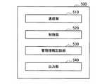
図11に示したように、本開示の一実施形態に係る管理サーバ500は、通信部510と、制御部520と、管理情報記録部530と、出力部540と、を含んで構成される。 As illustrated in FIG. 11, the
通信部510は、管理装置100との間でネットワーク600を介した通信を実行する。通信部510は、管理装置100との間で有線通信を行ってもよく、無線通信を行っても良い。通信部510は、管理装置100との間でネットワーク600を介した通信により取得した情報を制御部520へ供給する。 The
制御部520は、管理サーバ500の動作を制御する。制御部520は、管理装置100との間でネットワーク600を介した通信により通信部510が取得した情報を受け取り、その情報に応じた処理を実行する。 The
上述したような、管理装置100に電気的に接続される電子装置200の管理を行う場合は、制御部520は、管理装置100との間でネットワーク600を介した通信により通信部510が取得した、管理装置100の設置場所に関する情報と、その管理装置100に接続されている電子装置200の情報を用いて、電子装置200の管理を行う。電子装置200の管理を行う際には、制御部510は、管理情報記録部530に記録されている情報を参照することができる。 When managing the
管理情報記録部530は、制御部520による電子装置200の管理の際に用いられる情報が記録されている。管理情報記録部530に記録される情報としては、例えば、管理装置100の位置情報と、その管理装置100に接続しても良い電子装置200との対応関係(管理台帳データ)がある。管理情報記録部530がこのような情報(管理台帳データ)を記録しておくことで、制御部520は、管理装置100に電気的に接続される電子装置200の管理を行なうことが出来る。 In the management
出力部540は、制御部520の制御により、画像、音声、その他の外部に認識可能な情報を出力する。例えば、制御部520による電子装置200の管理により、正しい管理装置100に電子装置200が接続されていないことが分かれば、出力部540は、制御部520の制御により、画像、音声、光その他の外部に認識可能な何らかの情報を出力する。出力部540から画像、音声、光その他の外部に認識可能な何らかの情報を出力することで、管理サーバ500は、正しい管理装置100に電子装置200が接続されていないことを通知することができる。 The
もちろん、正しい管理装置100に電子装置200が接続されていないことを通知する方法はかかる例に限定されるものではない。例えば、制御部520によって、正しい管理装置100に電子装置200が接続されていないことが分かると、制御部520は、正しい管理装置100に電子装置200が接続されていない旨の情報を、通信部510からネットワーク600を通じてその管理装置100に送信してもよい。管理サーバ500から情報を受信した管理装置100は、電気的に接続されている電子装置200が、正しい管理装置100に接続されていないことを把握でき、正しい管理装置100に電子装置200が接続されていないことを、画像、音声、光その他の外部に認識可能な何らかの情報によって外部に通知することができる。 Of course, the method of notifying that the
以上、図11を用いて本開示の一実施形態に係る管理サーバ500の機能構成について説明した。次に、本開示の一実施形態に係る管理サーバ500の動作について説明する。 The functional configuration of the
[管理サーバの動作]
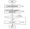
図12は、本開示の一実施形態に係る管理サーバ500の動作を示す流れ図である。図12に示した流れ図は、管理装置100に電気的に接続される電子装置200を、管理サーバ500で管理する際の動作について示したものである。以下、図12を用いて本開示の一実施形態に係る管理サーバ500の動作について説明する。Management server operation
FIG. 12 is a flowchart illustrating an operation of the
まず管理サーバ500は、電子装置200が電気的に接続されている管理装置100からネットワーク600を通じて、電子装置200の接続情報を取得する(ステップS101)。 First, the
上記ステップS101で、ネットワーク600を通じて電子装置200の接続情報を取得すると、続いて管理サーバ500は、上記ステップ101で取得した情報を用いて、電子装置200の接続情報を、保存している管理台帳データと照合する(ステップS102)。この情報の照合は制御部520が実行する。 When the connection information of the
管理サーバ500に保存されている管理台帳データの例を図13に示す。図13には、管理台帳データとして、電子装置200を特定するための機器IDと、その電子装置200が接続できる管理装置100の場所の情報とが対応付けて格納されている。制御部520は、ネットワーク600を通じて取得した電子装置200の接続情報と、管理台帳データとを照合することで、電子装置200が正しい管理装置100に接続されているかどうかを判断することが出来る。 An example of management ledger data stored in the
上記ステップS102で、電子装置200の接続情報を、保存している管理台帳データと照合すると、続いて管理サーバ500は、照合結果が一致しているかどうかを判定する(ステップS103)。この判定は制御部520が実行する。 When the connection information of the
上記ステップS103の判定の結果、電子装置200の接続情報と、保存している管理台帳データとが一致していれば管理サーバ500は特に何もしない。一方、上記ステップS103の判定の結果、電子装置200の接続情報と、保存している管理台帳データとが一致していなければ、続いて管理サーバ500は、電子装置200が正しい管理装置100に接続されていないことを示す何らかのアラートを出力する(ステップS104)。このアラートは、制御部520が出力部540に出力させる。 As a result of the determination in step S103, if the connection information of the
以上、図12を用いて本開示の一実施形態に係る管理サーバ500の動作について説明した。なお、図12に示した流れ図では、電子装置200の接続情報と、保存している管理台帳データとが一致していなければ、管理サーバ500は、電子装置200が正しい管理装置100に接続されていないことを示す何らかのアラートを出力するようにしていたが、本開示はかかる例に限定されるものではない。上述したように、正しい管理装置100に電子装置200が接続されていないことが分かると、管理サーバ500は、正しい管理装置100に電子装置200が接続されていない旨の情報を、通信部510からネットワーク600を通じてその管理装置100に送信してもよい。管理サーバ500から情報を受信した管理装置100は、電気的に接続されている電子装置200が、正しい管理装置100に接続されていないことを把握でき、正しい管理装置100に電子装置200が接続されていないことを、画像、音声、光その他の外部に認識可能な何らかの情報によって外部に通知することができる。また、正しい管理装置100に電子装置200が接続されていなければ、管理サーバ500は、正しくない管理装置100に対し、その接続された電子装置200へ通電しないよう指示してもよい。 The operation of the
管理サーバ500は、管理装置100からネットワーク600を通じて、管理装置100に電気的に接続されている電子装置200の情報を取得することで、電子装置200の状況を推定することができる。例えば、電子装置200がバッテリに蓄えられた電力により動作を行い、管理装置100に電気的に接続されることでそのバッテリを充電できる装置である場合、電子装置200は定期的にバッテリを充電する必要がある。 The
そこで、電子装置200を充電させる管理装置100を予め決めておく。そして、電子装置200のバッテリの時間あたりの使用率がある程度一定であれば、管理サーバ500は、管理装置100からネットワーク600を通じて、管理装置100に電気的に接続されている電子装置200の情報を取得した時間の情報を用いて、その電子装置200の充電率の情報を推定することができる。図13には、管理台帳データに、各電子装置の充電率の情報が記述されている様子が示されている。このように各電子装置の充電率を推定することで、管理サーバ500は、充電率が所定の値以下になった場合にその電子装置200の充電を促すようなアラートを出力することができる。 Therefore, a
また例えば、管理サーバ500は、管理装置100からネットワーク600を通じて、管理装置100に電気的に接続されている電子装置200の情報を取得することで、電子装置200の機能を変化させるようにしてもよい。例えば、電子装置200が複数の機能を有しており、状況に応じて機能を使い分けることができるように構成されている場合は、電子装置200を接続した管理装置100に応じてその中から一の機能を選択するよう、管理サーバ500が電子装置200の機能を変化させるようにしてもよい。 Further, for example, the
このように、管理サーバ500が、ネットワーク600を通じて電子装置200の情報を取得することで、その電子装置200が通電しているか否かにかかわらず、電子装置200の存在場所を特定することが出来る。電子装置200の存在場所を特定することで、管理サーバ500は、電子装置200が所定のエリアに存在しているかどうかを判断できる。また管理サーバ500が、ネットワーク600を通じて電子装置200の情報を取得することで、電子装置200が正常に使用されているかどうかの判別や、電子装置200の使用頻度、負荷を推定できる。また、電子装置200の情報を用いて、電子装置200の維持・メンテナンスや、装置の増設の要否判断などに利用できる。 As described above, the
<2.まとめ>
本実施形態によれば、以上のように、管理装置100と電子装置200との間で電力線を介した通信を行う。管理装置100は、従来の技術と同様に電力線を介して電子装置200と通信を行うことによって、電子装置200から識別情報を取得し、取得された識別情報に基づいて電力線により接続された電子装置200を特定する。ここで、電子装置200は、管理装置100が電力線に重畳させて送信した高周波信号から電力を得て駆動し、負荷変調により応答を行う。よって、管理装置100は、電力線により接続されている電子装置200の中に、電力が供給されていない電子装置200があったとしても、当該電子装置200を認識することができる。したがって、電力線により接続されている電子装置があったとしても電子装置に電力が供給されていない限り当該電子装置を認識することはできない従来の技術よりも、より確実に電力線により接続された電子装置200を特定することができる。<2. Summary>
According to the present embodiment, as described above, communication is performed between the
また、電子装置200は、管理装置100が電力線に重畳させて送信した高周波信号から電力を得て駆動し負荷変調により応答を行うので、電子装置200が電力線を介した通信に係る別途の電源回路を備えなくてよい。また、電子装置200は、NFCによる通信技術やRFID技術などの無線通信技術に用いられる通信デバイスと同様の構成の通信デバイスを用いて、管理装置100との間の電力線を介した通信を実現することが可能である。したがって、既存のPLCにより通信を行う従来の技術を用いる場合よりも、通信に係るデバイスの小型化が容易であり、またコストをより低減することができる。 In addition, since the
さらに、本実施形態に係る電力線を介した通信は、NFCによる通信技術やRFID技術などの無線通信技術と親和性があるので、当該無線通信技術における通信衝突防止技術(いわゆるアンチコリジョン)を用いることが可能である。したがって、既存のPLCにより通信を行う従来の技術を用いる場合において生じうる、電力線により接続された電子装置200に電力が供給されていたとしても当該電子装置200を特定することができないことを、防止することができる。 Furthermore, since communication via the power line according to the present embodiment is compatible with wireless communication technology such as NFC communication technology and RFID technology, communication collision prevention technology (so-called anti-collision) in the wireless communication technology should be used. Is possible. Therefore, it is possible to prevent the
したがって、本実施形態に係る管理装置100と本実施形態に係る電子装置200を有することによって、電力線により接続された電子装置を特定することが可能なシステムが実現される。 Therefore, by having the
そして本実施形態によれば、管理装置100に電子装置200が電気的に接続される際に、管理装置100から管理サーバ500へ、ネットワーク600を通じて、接続された電子装置200の情報を送信する。管理サーバ500は、管理装置100から送られて北情報を用いて、管理装置100に接続された電子装置200を管理することが出来る。 According to the present embodiment, when the
管理サーバ500が行うことができる電子装置200の管理には、上述したように、電子装置200が正しい管理装置100に接続されているかどうかの確認、電子装置200の充電率の推定、電子装置200の機能の変化等がある。管理装置100に電子装置200を接続するだけで、管理サーバ500は、管理装置100から電子装置200へ通電せずとも、電子装置200を管理することができる。 As described above, the management of the
コンピュータを、本実施形態に係る管理装置として機能させるためのプログラム(例えば、本実施形態に係る管理部として機能させるためのプログラム)によって、電力線により接続された電子装置を特定することができる。よって、コンピュータを、本実施形態に係る管理装置として機能させるためのプログラムが用いられることによって、電力線により接続された電子装置を特定することが可能な管理システムを実現することができる。 An electronic device connected by a power line can be specified by a program for causing the computer to function as a management device according to the present embodiment (for example, a program for causing the computer to function as a management unit according to the present embodiment). Therefore, the management system which can specify the electronic device connected by the power line is realizable by using the program for functioning a computer as a management apparatus which concerns on this embodiment.
コンピュータを、本実施形態に係る電子装置として機能させるためのプログラム(例えば、本実施形態に係る装置側電力線通信部として機能させるためのプログラム)によって、電力線を介して本実施形態に係る管理装置と通信を行うことができる。よって、コンピュータを、本実施形態に係る電子装置として機能させるためのプログラムが用いられることによって、電力線により接続された電子装置を特定することが可能な管理システムを実現することができる。 The management apparatus according to the present embodiment via the power line by the program for causing the computer to function as the electronic apparatus according to the present embodiment (for example, the program for functioning as the apparatus-side power line communication unit according to the present embodiment) Communication can be performed. Therefore, the management system which can specify the electronic device connected by the power line is realizable by using the program for functioning the computer as the electronic device according to the present embodiment.
以上、添付図面を参照しながら本開示の好適な実施形態について詳細に説明したが、本開示はかかる例に限定されない。本開示の属する技術の分野における通常の知識を有する者であれば、特許請求の範囲に記載された技術的思想の範疇内において、各種の変更例または修正例に想到し得ることは明らかであり、これらについても、当然に本開示の技術的範囲に属するものと了解される。 The preferred embodiments of the present disclosure have been described in detail above with reference to the accompanying drawings, but the present disclosure is not limited to such examples. It is obvious that a person having ordinary knowledge in the technical field to which the present disclosure belongs can come up with various changes or modifications within the scope of the technical idea described in the claims. Of course, it is understood that these also belong to the technical scope of the present disclosure.
なお、本技術は以下のような構成も取ることができる。
(1)
電力を供給する電力供給端子に、電子機器の機器端子が近接又は接続されたことにより生じる情報を取得する接続状態取得部と、
前記接続状態取得部が取得した情報を用いて、前記電力供給端子への前記機器端子の接続状態を管理する接続状態管理部と、
を備える、機器管理装置。
(2)
前記電力供給端子と前記電子機器との対応関係についての情報を記録する管理情報記録部をさらに備え、
前記接続状態管理部は、前記管理情報記録部に記録されている情報を用いて前記電力供給端子への前記電子機器の端子の接続状態を管理する、前記(1)に記載の機器管理装置。
(3)
前記機器状態管理部は、前記管理情報記録部に記録されている情報を参照した結果、前記電子機器の端子が正しい電力供給端子に接続されていない場合は所定の情報を出力させる、前記(2)に記載の機器管理装置。
(4)
前記機器状態管理部は、前記接続状態取得部が取得した情報を用いて、前記電子機器の充電状態を推定する、前記(1)から(3)のいずれかに記載の機器管理装置。
(5)
前記機器状態管理部は、前記電力供給端子に接続されている各電子機器の充電状態が把握できる情報を作成する、前記(4)に記載の機器管理装置。
(6)
前記機器状態管理部は、前記情報に基づいて、前記電力供給端子に接続されている各電子機器が所定のエリアにあるかを判断する、前記(1)から(5)のいずれかに記載の機器管理装置。
(7)
前記機器状態管理部は、前記接続状態取得部が取得した情報を用いて、前記電子機器の機能を変化させる、前記(1)から(6)のいずれかに記載の機器管理装置。
(8)
前記接続状態取得部は、前記電力供給端子と前記機器端子との接続に応じて行われる負荷変調によって前記電力供給端子と前記機器端子との間で情報が授受された結果生じる情報を取得する、前記(1)から(7)のいずれかに記載の機器管理装置。
(9)
電力を供給する電力供給端子に、電子機器の端子が近接又は接続されたことにより生じる情報を取得する接続状態取得ステップと、
前記接続状態取得部が取得した情報を用いて、前記電力供給端子への前記電子機器の端子の接続状態を管理する接続状態管理ステップと、
を備える、機器管理方法。
(10)
コンピュータに、
電力を供給する電力供給端子に、電子機器の端子が近接又は接続されたことにより生じる情報を取得する接続状態取得ステップと、
前記接続状態取得部が取得した情報を用いて、前記電力供給端子への前記電子機器の端子の接続状態を管理する接続状態管理ステップと、
を実行させる、コンピュータプログラム。In addition, this technique can also take the following structures.
(1)
A connection state acquisition unit that acquires information generated when a device terminal of an electronic device is close to or connected to a power supply terminal that supplies power; and
Using the information acquired by the connection state acquisition unit, a connection state management unit that manages the connection state of the device terminal to the power supply terminal,
A device management apparatus comprising:
(2)
A management information recording unit for recording information about a correspondence relationship between the power supply terminal and the electronic device;
The device management apparatus according to (1), wherein the connection state management unit manages a connection state of a terminal of the electronic device to the power supply terminal using information recorded in the management information recording unit.
(3)
The device state management unit outputs predetermined information when the terminal of the electronic device is not connected to a correct power supply terminal as a result of referring to the information recorded in the management information recording unit, (2 ) Device management device.
(4)
The device management apparatus according to any one of (1) to (3), wherein the device state management unit estimates a state of charge of the electronic device using information acquired by the connection state acquisition unit.
(5)
The device management apparatus according to (4), wherein the device state management unit creates information that allows grasping a charge state of each electronic device connected to the power supply terminal.
(6)
The device state management unit determines whether each electronic device connected to the power supply terminal is in a predetermined area based on the information, according to any one of (1) to (5). Equipment management device.
(7)
The device management apparatus according to any one of (1) to (6), wherein the device state management unit changes the function of the electronic device using information acquired by the connection state acquisition unit.
(8)
The connection state acquisition unit acquires information generated as a result of information exchanged between the power supply terminal and the device terminal by load modulation performed according to the connection between the power supply terminal and the device terminal. The device management apparatus according to any one of (1) to (7).
(9)
A connection state acquisition step of acquiring information generated when a terminal of an electronic device is close to or connected to a power supply terminal that supplies power; and
Using the information acquired by the connection state acquisition unit, a connection state management step of managing the connection state of the terminal of the electronic device to the power supply terminal,
A device management method comprising:
(10)
On the computer,
A connection state acquisition step of acquiring information generated when a terminal of an electronic device is close to or connected to a power supply terminal that supplies power; and
Using the information acquired by the connection state acquisition unit, a connection state management step of managing the connection state of the terminal of the electronic device to the power supply terminal,
A computer program that executes
500 管理サーバ
510 通信部
520 制御部
530 管理情報記録部
500
Claims (10)
Translated fromJapanese前記接続状態取得部が取得した情報を用いて、前記電力供給端子への前記機器端子の接続状態を管理する接続状態管理部と、
を備える、機器管理装置。A connection state acquisition unit that acquires information generated when a device terminal of an electronic device is close to or connected to a power supply terminal that supplies power; and
Using the information acquired by the connection state acquisition unit, a connection state management unit that manages the connection state of the device terminal to the power supply terminal,
A device management apparatus comprising:
前記接続状態管理部は、前記管理情報記録部に記録されている情報を用いて前記電力供給端子への前記電子機器の端子の接続状態を管理する、請求項1に記載の機器管理装置。A management information recording unit for recording information about a correspondence relationship between the power supply terminal and the electronic device;
The device management apparatus according to claim 1, wherein the connection state management unit manages a connection state of the terminal of the electronic device to the power supply terminal using information recorded in the management information recording unit.
前記接続状態取得部が取得した情報を用いて、前記電力供給端子への前記電子機器の端子の接続状態を管理する接続状態管理ステップと、
を備える、機器管理方法。A connection state acquisition step of acquiring information generated when a terminal of an electronic device is close to or connected to a power supply terminal that supplies power; and
Using the information acquired by the connection state acquisition unit, a connection state management step of managing the connection state of the terminal of the electronic device to the power supply terminal,
A device management method comprising:
電力を供給する電力供給端子に、電子機器の端子が近接又は接続されたことにより生じる情報を取得する接続状態取得ステップと、
前記接続状態取得部が取得した情報を用いて、前記電力供給端子への前記電子機器の端子の接続状態を管理する接続状態管理ステップと、
を実行させる、コンピュータプログラム。
On the computer,
A connection state acquisition step of acquiring information generated when a terminal of an electronic device is close to or connected to a power supply terminal that supplies power; and
Using the information acquired by the connection state acquisition unit, a connection state management step of managing the connection state of the terminal of the electronic device to the power supply terminal,
A computer program that executes
Priority Applications (3)
| Application Number | Priority Date | Filing Date | Title |
|---|---|---|---|
| JP2012028648AJP2013165448A (en) | 2012-02-13 | 2012-02-13 | Appliance management apparatus and appliance management method |
| US13/760,427US9581977B2 (en) | 2012-02-13 | 2013-02-06 | Appliance management apparatus and appliance management method |
| CN2013100484490ACN103248400A (en) | 2012-02-13 | 2013-02-06 | Appliance management apparatus and appliance management method |
Applications Claiming Priority (1)
| Application Number | Priority Date | Filing Date | Title |
|---|---|---|---|
| JP2012028648AJP2013165448A (en) | 2012-02-13 | 2012-02-13 | Appliance management apparatus and appliance management method |
Publications (2)
| Publication Number | Publication Date |
|---|---|
| JP2013165448Atrue JP2013165448A (en) | 2013-08-22 |
| JP2013165448A5 JP2013165448A5 (en) | 2015-03-26 |
Family
ID=48927647
Family Applications (1)
| Application Number | Title | Priority Date | Filing Date |
|---|---|---|---|
| JP2012028648APendingJP2013165448A (en) | 2012-02-13 | 2012-02-13 | Appliance management apparatus and appliance management method |
Country Status (3)
| Country | Link |
|---|---|
| US (1) | US9581977B2 (en) |
| JP (1) | JP2013165448A (en) |
| CN (1) | CN103248400A (en) |
Families Citing this family (9)
| Publication number | Priority date | Publication date | Assignee | Title |
|---|---|---|---|---|
| JP5874311B2 (en) | 2011-10-24 | 2016-03-02 | ソニー株式会社 | Electric power demand prediction apparatus, electric power demand prediction method, and electric power demand prediction system |
| US9214988B2 (en)* | 2012-02-06 | 2015-12-15 | Qualcomm Incorporated | Methods and apparatus for improving peer communications using an active communication mode |
| JP2013165447A (en) | 2012-02-13 | 2013-08-22 | Sony Corp | Transmission apparatus, electronic appliance, reception apparatus, and authentication system |
| JP6376919B2 (en)* | 2014-09-22 | 2018-08-22 | キヤノン株式会社 | Power supply device and electronic device |
| JP6494227B2 (en) | 2014-09-22 | 2019-04-03 | キヤノン株式会社 | Power supply apparatus, control method, and program |
| JP6418867B2 (en) | 2014-09-22 | 2018-11-07 | キヤノン株式会社 | Power supply device |
| JP6406955B2 (en) | 2014-09-22 | 2018-10-17 | キヤノン株式会社 | Electronics |
| DE102015008699B4 (en)* | 2015-07-08 | 2017-05-11 | Jenoptik Advanced Systems Gmbh | Residual current sensor for a residual current device for monitoring an electrical load for a vehicle |
| WO2017156675A1 (en)* | 2016-03-14 | 2017-09-21 | 富士通株式会社 | Operation administration maintenance system |
Citations (6)
| Publication number | Priority date | Publication date | Assignee | Title |
|---|---|---|---|---|
| JP2005294991A (en)* | 2004-03-31 | 2005-10-20 | Hitachi Ltd | Power line carrier communication apparatus and power line carrier communication method |
| JP2006279650A (en)* | 2005-03-30 | 2006-10-12 | Kddi Corp | Power line communication management method and system, and power outlet management method and apparatus |
| JP2008153852A (en)* | 2006-12-15 | 2008-07-03 | Mitsubishi Electric Corp | Power line transfer system, power supply device, electric lock device, server |
| JP2009009187A (en)* | 2007-06-26 | 2009-01-15 | Felica Networks Inc | Information processor and data processing method |
| JP2009254052A (en)* | 2008-04-02 | 2009-10-29 | Toyota Motor Corp | Charging service system, charging service station, and electric vehicle |
| JP2010134816A (en)* | 2008-12-08 | 2010-06-17 | Hochiki Corp | Product safety management network system and method |
Family Cites Families (55)
| Publication number | Priority date | Publication date | Assignee | Title |
|---|---|---|---|---|
| KR100261512B1 (en)* | 1998-06-17 | 2000-07-15 | 김철 | Remote control method using bidirectional power-line communication |
| IT1320622B1 (en)* | 2000-09-05 | 2003-12-10 | Wrap Spa | SYSTEM AND DEVICE FOR THE MONITORING OF AT LEAST ONE ELECTRIC HOUSEHOLD, IN PARTICULAR A HOUSEHOLD APPLIANCE. |
| JP2003110471A (en) | 2001-09-26 | 2003-04-11 | Sanyo Electric Co Ltd | Power line connection equipment control system and connection apparatus |
| JP2004094607A (en)* | 2002-08-30 | 2004-03-25 | Matsushita Electric Ind Co Ltd | Portable information device, method and program for optimizing state of charge of battery, battery management server, and method and program for optimizing state of charge of battery-powered electric device |
| JP4248883B2 (en)* | 2003-01-06 | 2009-04-02 | 富士通株式会社 | Battery alarm voltage setting device and battery alarm voltage setting method in battery management server |
| DE102004007904B4 (en)* | 2004-02-18 | 2008-07-03 | Vb Autobatterie Gmbh & Co. Kgaa | Method for determining at least one parameter for the state of an electrochemical storage battery and monitoring device |
| US8427109B2 (en)* | 2004-04-06 | 2013-04-23 | Chevron Technology Ventures Llc | Battery state of charge reset |
| JP3960321B2 (en) | 2004-04-30 | 2007-08-15 | ソニー株式会社 | Electronics |
| CN101080916B (en)* | 2004-12-17 | 2012-07-04 | 国际商业机器公司 | Communication relay device, information processing system, control method, and program |
| JP2006180384A (en)* | 2004-12-24 | 2006-07-06 | Toshiba Corp | Communication unit and communication method thereof |
| US7813842B2 (en)* | 2006-03-09 | 2010-10-12 | Sony Corporation | Systems and methods for use in providing local power line communication |
| US8994276B2 (en)* | 2006-03-28 | 2015-03-31 | Wireless Environment, Llc | Grid shifting system for a lighting circuit |
| US8519566B2 (en)* | 2006-03-28 | 2013-08-27 | Wireless Environment, Llc | Remote switch sensing in lighting devices |
| US8491159B2 (en)* | 2006-03-28 | 2013-07-23 | Wireless Environment, Llc | Wireless emergency lighting system |
| US8829799B2 (en)* | 2006-03-28 | 2014-09-09 | Wireless Environment, Llc | Autonomous grid shifting lighting device |
| JP2007336174A (en)* | 2006-06-14 | 2007-12-27 | Matsushita Electric Ind Co Ltd | Power line communication terminal device and power line communication circuit |
| US7415623B2 (en)* | 2006-07-31 | 2008-08-19 | Motorola, Inc. | System for managing the power source life between multiple individually powered devices in a wired system and method of using same |
| JP4907277B2 (en)* | 2006-09-15 | 2012-03-28 | パナソニック株式会社 | Power line communication apparatus, power line communication method, and power line communication system |
| JP4039451B1 (en)* | 2006-09-20 | 2008-01-30 | 富士ゼロックス株式会社 | Power line communication device, power supply system, and program |
| US8050803B2 (en)* | 2006-09-20 | 2011-11-01 | Fuji Xerox Co., Ltd. | Power feeding system, electrical apparatus, power feeding apparatus, and computer readable storage medium |
| US20080080457A1 (en)* | 2006-09-29 | 2008-04-03 | Cole Terry L | Connection manager responsive to power state |
| US8032150B2 (en)* | 2006-09-29 | 2011-10-04 | Globalfoundries Inc. | Connection manager with location learning |
| US7885222B2 (en)* | 2006-09-29 | 2011-02-08 | Advanced Micro Devices, Inc. | Task scheduler responsive to connectivity prerequisites |
| US20080080419A1 (en)* | 2006-09-29 | 2008-04-03 | Cole Terry L | Connection manager with fast connect |
| US20080081606A1 (en)* | 2006-09-29 | 2008-04-03 | Cole Terry L | Connection manager with branded connection notification |
| US20080080413A1 (en)* | 2006-09-29 | 2008-04-03 | Advanced Micro Devices, Inc. | Connection manager with remote portal service |
| US20080080458A1 (en)* | 2006-09-29 | 2008-04-03 | Cole Terry L | Connection manager with deferred configuration |
| US20080081580A1 (en)* | 2006-09-29 | 2008-04-03 | Cole Terry L | Connection manager with selective support determination based on problem diagnosis |
| US20080080412A1 (en)* | 2006-09-29 | 2008-04-03 | Advanced Micro Devices, Inc. | Connection manager with communication load monitoring |
| US20080081597A1 (en)* | 2006-09-29 | 2008-04-03 | Cole Terry L | Connection manager with prompter for service subscription |
| US7430675B2 (en)* | 2007-02-16 | 2008-09-30 | Apple Inc. | Anticipatory power management for battery-powered electronic device |
| KR100992294B1 (en)* | 2008-02-29 | 2010-11-05 | 김선영 | consent |
| JP5228779B2 (en)* | 2008-10-10 | 2013-07-03 | 富士通株式会社 | Information system, server, service providing method, and program |
| US8674823B1 (en)* | 2009-05-12 | 2014-03-18 | Plug ID, LLC. | Power management system |
| US8775846B2 (en)* | 2009-07-10 | 2014-07-08 | Protonex Technology Corporation | Portable power manager having one or more device ports for connecting with external power loads |
| US20110099507A1 (en)* | 2009-10-28 | 2011-04-28 | Google Inc. | Displaying a collection of interactive elements that trigger actions directed to an item |
| JP5446922B2 (en)* | 2010-01-25 | 2014-03-19 | ソニー株式会社 | Power management apparatus, electronic device, and electronic device registration method |
| JP2011155323A (en)* | 2010-01-25 | 2011-08-11 | Sony Corp | Digital watermark generating apparatus, electronic-watermark verifying apparatus, method of generating digital watermark, and method of verifying digital watermark |
| JP2011154410A (en)* | 2010-01-25 | 2011-08-11 | Sony Corp | Analysis server and method of analyzing data |
| JP2011155711A (en)* | 2010-01-25 | 2011-08-11 | Sony Corp | Power management apparatus and method of providing game contents |
| JP5585097B2 (en) | 2010-01-25 | 2014-09-10 | ソニー株式会社 | Power management apparatus and electronic device registration method |
| JP2011155710A (en)* | 2010-01-25 | 2011-08-11 | Sony Corp | Power management apparatus, electronic apparatus, and method of managing power |
| JP5659506B2 (en)* | 2010-03-03 | 2015-01-28 | 富士通株式会社 | Power leveling control device, power leveling control method, and program |
| JP5510019B2 (en)* | 2010-04-16 | 2014-06-04 | 富士通株式会社 | Power control method, program and apparatus |
| US20120053742A1 (en)* | 2010-08-30 | 2012-03-01 | Sony Corporation | Information processing apparatus, information processing method, information processing system, and transportation means |
| JP2012252580A (en) | 2011-06-03 | 2012-12-20 | Sony Corp | Power control device, power management device and power management system |
| US8326467B2 (en)* | 2011-09-06 | 2012-12-04 | General Electric Company | Controller and method of controlling a power system |
| JP5874311B2 (en) | 2011-10-24 | 2016-03-02 | ソニー株式会社 | Electric power demand prediction apparatus, electric power demand prediction method, and electric power demand prediction system |
| JP5899830B2 (en) | 2011-11-09 | 2016-04-06 | ソニー株式会社 | Power management apparatus, power management method, and demand notification apparatus |
| JP5857646B2 (en) | 2011-11-10 | 2016-02-10 | ソニー株式会社 | Power management apparatus, power management method, and demand notification apparatus |
| JP2013165447A (en) | 2012-02-13 | 2013-08-22 | Sony Corp | Transmission apparatus, electronic appliance, reception apparatus, and authentication system |
| JP2013165461A (en) | 2012-02-13 | 2013-08-22 | Sony Corp | Converter and program |
| JP2013165457A (en) | 2012-02-13 | 2013-08-22 | Sony Corp | Converter and program |
| JP2013165619A (en) | 2012-02-13 | 2013-08-22 | Sony Corp | Power supplying apparatus and power supplying method |
| JP2014017949A (en) | 2012-07-06 | 2014-01-30 | Sony Corp | Power management device, power supply device, power supply system, power management method and power supply method |
- 2012
- 2012-02-13JPJP2012028648Apatent/JP2013165448A/enactivePending
- 2013
- 2013-02-06CNCN2013100484490Apatent/CN103248400A/enactivePending
- 2013-02-06USUS13/760,427patent/US9581977B2/ennot_activeExpired - Fee Related
Patent Citations (6)
| Publication number | Priority date | Publication date | Assignee | Title |
|---|---|---|---|---|
| JP2005294991A (en)* | 2004-03-31 | 2005-10-20 | Hitachi Ltd | Power line carrier communication apparatus and power line carrier communication method |
| JP2006279650A (en)* | 2005-03-30 | 2006-10-12 | Kddi Corp | Power line communication management method and system, and power outlet management method and apparatus |
| JP2008153852A (en)* | 2006-12-15 | 2008-07-03 | Mitsubishi Electric Corp | Power line transfer system, power supply device, electric lock device, server |
| JP2009009187A (en)* | 2007-06-26 | 2009-01-15 | Felica Networks Inc | Information processor and data processing method |
| JP2009254052A (en)* | 2008-04-02 | 2009-10-29 | Toyota Motor Corp | Charging service system, charging service station, and electric vehicle |
| JP2010134816A (en)* | 2008-12-08 | 2010-06-17 | Hochiki Corp | Product safety management network system and method |
Also Published As
| Publication number | Publication date |
|---|---|
| US9581977B2 (en) | 2017-02-28 |
| US20130211606A1 (en) | 2013-08-15 |
| CN103248400A (en) | 2013-08-14 |
Similar Documents
| Publication | Publication Date | Title |
|---|---|---|
| RU2585658C2 (en) | Transmitting device, receiving device and communication system | |
| JP2013165448A (en) | Appliance management apparatus and appliance management method | |
| JP5177270B2 (en) | COMMUNICATION DEVICE, COMMUNICATION SYSTEM, AND COMMUNICATION METHOD | |
| JP5924050B2 (en) | Power feeding device, power receiving device, power feeding method, power receiving method, and program | |
| US9268924B2 (en) | Transmission apparatus, electronic appliance, reception apparatus, and authentication system | |
| JP2013165619A (en) | Power supplying apparatus and power supplying method | |
| JP5899994B2 (en) | Power feeding device, power receiving device, and program | |
| JP6243099B2 (en) | Power feeding device, power receiving device, state management method, and program | |
| JP2013187690A (en) | Communication apparatus, electronic apparatus, relay apparatus, communication method, and communication system | |
| JP5920365B2 (en) | Power receiving device and program | |
| JP6241421B2 (en) | Control device, control method, and program | |
| JP2013187691A (en) | Communication apparatus, electronic apparatus, and communication system | |
| JP2013165449A (en) | Power supply device and power supply method |
Legal Events
| Date | Code | Title | Description |
|---|---|---|---|
| A521 | Request for written amendment filed | Free format text:JAPANESE INTERMEDIATE CODE: A523 Effective date:20150205 | |
| A621 | Written request for application examination | Free format text:JAPANESE INTERMEDIATE CODE: A621 Effective date:20150205 | |
| A977 | Report on retrieval | Free format text:JAPANESE INTERMEDIATE CODE: A971007 Effective date:20160125 | |
| A131 | Notification of reasons for refusal | Free format text:JAPANESE INTERMEDIATE CODE: A131 Effective date:20160202 | |
| A521 | Request for written amendment filed | Free format text:JAPANESE INTERMEDIATE CODE: A523 Effective date:20160328 | |
| A02 | Decision of refusal | Free format text:JAPANESE INTERMEDIATE CODE: A02 Effective date:20160816 | |
| A521 | Request for written amendment filed | Free format text:JAPANESE INTERMEDIATE CODE: A523 Effective date:20171226 |