JP2013165334A - Mobile terminal device - Google Patents
Mobile terminal deviceDownload PDFInfo
- Publication number
- JP2013165334A JP2013165334AJP2012026261AJP2012026261AJP2013165334AJP 2013165334 AJP2013165334 AJP 2013165334AJP 2012026261 AJP2012026261 AJP 2012026261AJP 2012026261 AJP2012026261 AJP 2012026261AJP 2013165334 AJP2013165334 AJP 2013165334A
- Authority
- JP
- Japan
- Prior art keywords
- touch panel
- terminal device
- area
- mobile terminal
- screen
- Prior art date
- Legal status (The legal status is an assumption and is not a legal conclusion. Google has not performed a legal analysis and makes no representation as to the accuracy of the status listed.)
- Pending
Links
- 238000001514detection methodMethods0.000claimsdescription7
- 210000003811fingerAnatomy0.000description29
- 238000010586diagramMethods0.000description2
- 238000010079rubber tappingMethods0.000description2
- 125000002066L-histidyl groupChemical group[H]N1C([H])=NC(C([H])([H])[C@](C(=O)[*])([H])N([H])[H])=C1[H]0.000description1
- 230000001133accelerationEffects0.000description1
- 230000000694effectsEffects0.000description1
- 238000005516engineering processMethods0.000description1
- 210000001145finger jointAnatomy0.000description1
- 230000005057finger movementEffects0.000description1
- 239000004519greaseSubstances0.000description1
- 239000004973liquid crystal related substanceSubstances0.000description1
- 210000004932little fingerAnatomy0.000description1
- 238000000034methodMethods0.000description1
- 210000004243sweatAnatomy0.000description1
Images


Landscapes
- Position Input By Displaying (AREA)
- User Interface Of Digital Computer (AREA)
- Telephone Set Structure (AREA)
- Telephone Function (AREA)
Abstract
Description
Translated fromJapanese本発明は、タッチパネルを備えた携帯端末装置に関する。 The present invention relates to a mobile terminal device provided with a touch panel.
通常、携帯電話やPDA装置などでは、表示パネルの画面に表示されたアイコンやリンク等の上にカーソルを操作ボタンで移動し、その状態で決定ボタンを押すと、アイコンやリンク等に応じた機能が実行されるようになっている。 Normally, in a mobile phone or PDA device, when the cursor is moved with an operation button on an icon or link displayed on the screen of the display panel and the enter button is pressed in that state, a function corresponding to the icon or link etc. Is to be executed.
さらに近年、スマートフォンに代表される持ち運び可能な携帯端末装置では、上記のようなカーソル移動や決定は、表示画面上に搭載されたタッチパネルを指で操作して行われている。 In recent years, in portable terminal devices such as smartphones, the above-described cursor movement and determination are performed by operating a touch panel mounted on a display screen with a finger.
しかし、表示画面上にタッチパネルが搭載されている携帯端末装置は、タッチパネルを操作する指で表示画面が隠れてしまうものである。 However, in a mobile terminal device in which a touch panel is mounted on a display screen, the display screen is hidden by a finger that operates the touch panel.
このため、アイコンやリンク等の被選択画像の領域がもともと小さい場合や、表示画面が小さくて被選択画像の領域を小さくしなければならない場合などにおいては、目的の被選択画像上を指で押したと思った位置と実際に押した位置とが違ってしまうことがある。この結果、操作者は隣接する別の被選択画像を選んでしまい、操作をやり直さねばならなくなる。 For this reason, when the area of the selected image such as an icon or link is originally small, or when the display screen is small and the area of the selected image must be reduced, the user selects the desired selected image with a finger. The position where you thought you were and the position you actually pressed might be different. As a result, the operator must select another adjacent selected image and must perform the operation again.
また、表示画面上にタッチパネルが存在するため、タッチパネルをスライドした又は押したときの指の脂や汗で表示画面が汚れ、表示品位を落としてしまう。 In addition, since the touch panel exists on the display screen, the display screen is soiled by finger grease or sweat when the touch panel is slid or pressed, and the display quality is deteriorated.
上記の課題を解決しえる技術として、特許文献1〜4等には、表示パネルが搭載された表面とは反対側の裏面に、表示画面上のカーソルを操作できるタッチパネルを搭載した携帯端末装置が提案されている。 As technologies that can solve the above problems, Patent Documents 1 to 4 and the like include a portable terminal device that includes a touch panel that can operate a cursor on a display screen on the back surface opposite to the surface on which a display panel is mounted. Proposed.
特許文献1〜4等に開示される携帯端末装置のように、表示画面上にタッチパネルを搭載せずに、表示画面とは反対側の面に搭載すれば、表示画面を指で触らず、かつ、被選択画像上へのカーソル合わせを正確に行えると思われる。 If it is mounted on the surface opposite to the display screen without mounting the touch panel on the display screen, as in the portable terminal devices disclosed in Patent Documents 1 to 4, etc., the display screen is not touched with a finger, and It seems that the cursor can be accurately aligned on the selected image.
しかしながら、特許文献1〜4等に開示される携帯端末装置の場合、背面のタッチパネルの位置は固定されている。例えば、矩形の携帯端末装置において、操作者が装置の長手方向下部を片手で持って背面のタッチパネルをその持ち手の人差し指で操作できるように、該タッチパネルは装置背面の長手方向の上側部に位置している。 However, in the case of the mobile terminal device disclosed in Patent Literatures 1 to 4 and the like, the position of the touch panel on the back is fixed. For example, in a rectangular portable terminal device, the touch panel is positioned on the upper part in the longitudinal direction on the back of the device so that the operator can hold the lower part of the device in the longitudinal direction with one hand and operate the back touch panel with the index finger of the hand. doing.
そのため、近年のスマートフォンのように矩形の筐体を縦長画面の状態から横長画面の状態に変えて使用するものにおいては、装置の長手方向を横方向にした際タッチパネルの位置が持ち手の人差し指の位置に対応しなくなり、片手でタッチパネルを操作し難くなるといった課題が生じる。 For this reason, in the case of using a rectangular casing from a portrait screen to a landscape screen like in recent smartphones, the touch panel position is the index finger of the hand when the longitudinal direction of the device is in the landscape direction. There is a problem that it becomes difficult to operate the touch panel with one hand because it does not correspond to the position.
そこで本発明の目的の一例は、表示パネルの画面上のカーソルを操作できるタッチパネルを該表示パネルとは反対側の面に備えた携帯端末装置において、その装置の使用向きを変えてもタッチパネルの片手操作を可能とすることにある。 Accordingly, an example of the object of the present invention is to provide a portable terminal device having a touch panel that can operate a cursor on the screen of the display panel on the surface opposite to the display panel, even if the direction of use of the device is changed, It is to enable operation.
本発明の一つの態様は、携帯端末装置であって、表示パネルが搭載された第一の面と、タッチパネルが搭載された、該第一の面とは反対側の第二の面とを備える。さらに、この態様は、携帯端末装置を使用する際の、前記第一の面の法線方向を回転軸とする前記携帯端末装置の回転角度に応じて、前記タッチパネルの全領域が有効領域と非有効領域に区分して設定されることを特徴とする。 One aspect of the present invention is a mobile terminal device comprising a first surface on which a display panel is mounted and a second surface on the opposite side of the first surface on which a touch panel is mounted. . Further, in this aspect, when the mobile terminal device is used, the entire area of the touch panel is determined not to be an effective area according to the rotation angle of the mobile terminal apparatus with the normal direction of the first surface as the rotation axis. It is characterized by being divided into effective areas.
本発明によれば、表示パネルの画面上のカーソルを操作できるタッチパネルを該表示パネルとは反対側の面に備えた携帯端末装置において、その装置の使用向きを変えても、片手の指でタッチパネルを容易に操作することが可能となる。 According to the present invention, in a portable terminal device having a touch panel that can operate a cursor on the screen of the display panel on the surface opposite to the display panel, the touch panel can be touched with a finger of one hand even if the direction of use of the device is changed. Can be easily operated.
以下、本発明の実施の形態について図面を参照して説明する。 Hereinafter, embodiments of the present invention will be described with reference to the drawings.
ここでは、本発明の携帯端末装置として、筐体正面に液晶表示パネルが搭載されているスマートフォンを例にとって説明するが、本発明はそれ以外の携帯電話やPDA装置などの携帯端末にも適用可能である。 Here, as an example of the mobile terminal device of the present invention, a smartphone having a liquid crystal display panel mounted on the front surface of the housing will be described as an example. However, the present invention can also be applied to other mobile terminals such as mobile phones and PDA devices. It is.
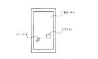
図1は本実施形態のスマートフォンを、表示画面側の第一面から見た平面図であり、図2は図1の表示画面とは反対側の第二面を示した平面図である。 FIG. 1 is a plan view of the smartphone according to the present embodiment as viewed from the first surface on the display screen side, and FIG. 2 is a plan view showing the second surface on the side opposite to the display screen in FIG.
図1に示すように、スマートフォンの第一面(正面)にはLCDや有機ELなどからなる表示パネル1が搭載されている。表示パネル1とは反対側に位置するスマートフォンの第二面(背面)には、図2に示すようにタッチパネル2が搭載されている。表示パネル1の画面には図1のようなアイコン3やカーソル4が表示されており、操作者がタッチパネル2上で指をスライドさせることにより、表示画面上をカーソル4が動く。 As shown in FIG. 1, the display panel 1 which consists of LCD, organic EL, etc. is mounted in the 1st surface (front) of a smart phone. A touch panel 2 is mounted on the second surface (rear surface) of the smartphone located on the opposite side of the display panel 1 as shown in FIG. An icon 3 and a cursor 4 as shown in FIG. 1 are displayed on the screen of the display panel 1. When the operator slides a finger on the touch panel 2, the cursor 4 moves on the display screen.
このような態様のスマートフォンでは、操作者はスマートフォン正面の表示パネル1の画面を見ながらスマートフォン背面のタッチパネル2を指で操作して、表示画面上の被選択画像であるアイコン3に正確にカーソル4を合わせることができる。アイコン3が操作者の指で隠れることがないからである。そして、複数のアイコンのうちの目的のアイコン3上にカーソル4が合ったところで、タッチパネル2を指でタップすると、そのアイコン3が決定され、そのアイコン3に対応する機能が実行される。 In such a smart phone, the operator operates the touch panel 2 on the back of the smart phone with his / her finger while looking at the screen of the display panel 1 on the front of the smart phone, and accurately moves the cursor 4 to the icon 3 which is the selected image on the display screen. Can be combined. This is because the icon 3 is not hidden by the operator's finger. When the cursor 4 is positioned on the target icon 3 among the plurality of icons, when the touch panel 2 is tapped with a finger, the icon 3 is determined and the function corresponding to the icon 3 is executed.
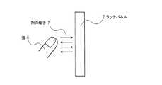
図3と図4はタッチパネル2を横から見た図である。上記したアイコン3の選択方法として、図3に示すようにタッチパネル2を指5で一度タップするという動き6、または、図4に示すようにタッチパネル2を指5で2度タップするという動作7が考えられる。 3 and 4 are views of the touch panel 2 as viewed from the side. As the method for selecting the icon 3, the movement 6 of tapping the touch panel 2 once with the finger 5 as shown in FIG. 3 or the operation 7 of tapping the touch panel 2 twice with the finger 5 as shown in FIG. Conceivable.
上記した実施形態によれば、表示画面が指で隠れないため、操作者が表示画面上の意図しないアイコンやリンクなどの被選択画像を選択してしまうといった間違いを防ぐことができる。 According to the above-described embodiment, since the display screen is not hidden with a finger, it is possible to prevent a mistake that the operator selects an unselected image such as an icon or a link on the display screen.
さらに、被選択画像の領域のサイズに関係なく操作者はその領域に正確にカーソルを合わせられるため、アイコンのような被選択画像の領域を小さく設計することができ、画面設計の自由度が増す。また、表示画面に指を触れることなく画面の操作を行えるため、画面の汚れや表示品位の低下を防ぐことができる。 Further, since the operator can accurately place the cursor on the selected image area regardless of the size of the selected image area, the area of the selected image such as an icon can be designed to be small, and the degree of freedom in screen design is increased. . In addition, since the screen can be operated without touching the display screen, it is possible to prevent the screen from being soiled and the display quality from being deteriorated.
なお、本発明は上記の実施形態に限られない。すなわち、背面のタッチパネル2はカーソルの操作に用いるだけでなく、画面のスクロールや、一部の画像の拡大・縮小にも用いることができる。また、上記した表示パネル1はタッチパネルが搭載されていないものとしたが、本発明はこの限りでない。例えば、正面の表示パネル1上にタッチパネルが搭載されている従来どおりの携帯端末装置において背面に上記タッチパネル2を設け、正面側のタッチパネルと併用するといった態様であってもよい。 The present invention is not limited to the above embodiment. That is, the rear touch panel 2 can be used not only for cursor operation, but also for scrolling the screen and enlarging / reducing some images. Moreover, although the above-mentioned display panel 1 shall not be equipped with the touch panel, this invention is not this limitation. For example, in a conventional portable terminal device in which a touch panel is mounted on the front display panel 1, the touch panel 2 may be provided on the back surface and used in combination with the front touch panel.
上記した実施形態において、タッチパネル2を矩形のスマートフォンの背面に搭載するとき、タッチパネル2を、特に図2に示されるように背面の長手方向の上側部に配置することにより、スマートフォンの長手方向の下部を片手で持った状態で、その持ち手の人差し指でタッチパネル2を操作しやすくなる。また、タッチパネル2の誤操作も防止できる。 In the above-described embodiment, when the touch panel 2 is mounted on the back surface of a rectangular smartphone, the touch panel 2 is arranged on the upper side in the longitudinal direction of the back surface as shown in FIG. With one hand held, the touch panel 2 can be easily operated with the index finger of the hand. Further, erroneous operation of the touch panel 2 can be prevented.
しかしこの配置に限定すると、スマートフォンの表示画面の使用向き(例えば横長画面として使用する場合)によっては、持ち手の人差し指とタッチパネル2の位置が対応しない虞がある。結果、タッチパネル2を片手で操作しづらくなったり、操作する手が限定されたりする。 However, if this arrangement is limited, the index finger of the hand and the position of the touch panel 2 may not correspond to each other depending on the use direction of the display screen of the smartphone (for example, when used as a horizontally long screen). As a result, it becomes difficult to operate the touch panel 2 with one hand, or the hand to operate is limited.
そこで本発明は、背面に搭載するタッチパネルのエリアをより大きくし、該タッチパネルの全領域のうちの、画面の使用向きに応じて上側に来る領域のみを、操作が有効な領域とするといった態様を提案する。 Therefore, the present invention has a mode in which the area of the touch panel mounted on the back surface is made larger, and only the area that comes to the upper side in accordance with the use direction of the screen among the entire area of the touch panel is set as an effective operation area. suggest.
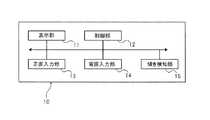
以下、この態様例を詳述する。図5のブロック図で示されるように、この態様の携帯端末装置10は、装置正面側に配置された表示部11と、表示部11上に配置されたタッチパネルを含む正面入力部13と、装置裏面に配置されたタッチパネルとしての背面入力部14と、装置の表示画面の回転角度(ここでは、装置正面の法線方向を回転軸とする回転角度)を検知する傾き検知部15と、それらを制御する制御部12とを有する。傾き検知部15は、例えば加速度センサーで構成されている。 Hereinafter, this embodiment example will be described in detail. As shown in the block diagram of FIG. 5, the mobile
図6は携帯端末装置10の外観の概略図であり、図6(A)は縦長画面の状態での装置正面図、図6(B)はその縦長画面の状態での装置背面図である。図6(C)は横長画面の状態、すなわち図6(A)の縦長画面を右に90度回転させた状態での装置正面図、図6(D)はその横長画面の状態での装置背面図である。また図7は、図6(B)の背面図に、片手で装置10を持っているときの指の位置を示した図である。 6A and 6B are schematic views of the appearance of the mobile
図6に示すように、携帯端末装置10の正面側の表示部11上には、表示部11と同じ形状及び面積のタッチパネルが正面入力部13として配置されている。さらに装置10の背面には、表示部11と同じ形状及び面積のタッチパネルが背面入力部14として配置されている。 As shown in FIG. 6, a touch panel having the same shape and area as the
タッチパネル14は、接触を検知する領域として、4つの領域(a),(b),(c),(d)に論理的に分割されているとする。これら4つの領域は、長方形のタッチパネル全領域を上下に等分し、さらに左右に等分してなる。 It is assumed that the
次に、背面入力部14としてのタッチパネルの動作について、図8を用いて説明する。 Next, the operation of the touch panel as the
略長方形の正面と背面を有する携帯端末装置10について、図6(A)及び図6(B)に示すように装置10の長手方向が上下方向(縦方向)に対応している状態が初期の状態とされる。この状態において操作者は、まず、制御部12に初期値を設定する。初期値として、操作者は、制御部12を用いて領域(a)及び領域(b)を有効にし、領域(c)及び領域(d)を無効にする(図8のステップS100)。また、この状態において傾き検知部15で得られる値が、制御部12により記憶される。 For the mobile
さらに、表示部11の画面の縦横サイズと、タッチパネル14の有効な領域(ここでは、領域(a)と領域(b)を合わせた領域)の縦横サイズとの比に応じて、タッチパネル操作時の操作係数が制御部12で計算される。操作係数とは、タッチパネル上の第一の位置から第二の位置までの操作の距離に掛ける係数であり、例えばタッチパネルの端から端まで指を操作した時にカーソルが画面の端から端まで移動するように、上記の操作係数が決定される。 Further, according to the ratio between the vertical and horizontal size of the screen of the
続いて、装置10が傾いたかどうかが判定される(図8のステップS101)。傾き検知部15で得られる値と初期状態での値との差分に基づいて、傾き角度を計算することができる。ここでは、略90度単位で0度、90度、180度、270度といった4つの傾き(表示画面の法線を中心軸とした装置10の回転角度)が判定される。 Subsequently, it is determined whether or not the
装置10が初期状態から傾いた場合、制御部12は、装置10の傾き角度に応じて、タッチパネル14における有効領域と無効領域を変更する(図8のステップS102,S103)。例えば、図6(A)及び図6(B)に示される装置10が、図6(C)及び図6(D)に示すように正面から見て右に90度傾いたとする。この場合、装置10の背面の上側領域となったのは領域(b)及び領域(d)なので、領域(b)及び領域(d)が有効にされ、領域(a)及び領域(c)は無効にされる。 When the
このとき、表示部11の画面の縦横サイズと、タッチパネル14の有効な領域(ここでは、領域(b)と領域(d)を合わせた領域)の縦横サイズとの比に応じて、タッチパネル操作時の操作係数が制御部12で計算され、再設定される(図8のステップS104)。 At this time, when the touch panel is operated according to the ratio between the vertical and horizontal size of the screen of the
操作者が装置10の動作を継続する場合はステップS101からS104までの設定が繰り返され、そうでなければ当該設定は終了する(図8のステップS105)。 When the operator continues the operation of the
このように、背面のタッチパネルの全領域に対して論理的に有効領域と無効領域を設定することで、装置10の画面の使用向きに応じて上側に来る領域のみを、操作可能領域として使用することができる。 In this way, by setting the effective area and the invalid area logically for the entire area of the touch panel on the back side, only the area that is on the upper side according to the use direction of the screen of the
なお、図6の態様ではタッチパネルの全領域が略均等な4つの領域に分割され、その内の2つの上側領域が有効とされ、画面の回転角度は4段階で判定されるが、本発明はこの態様に限られない。 In the aspect of FIG. 6, the entire area of the touch panel is divided into four substantially equal areas, and the two upper areas are valid, and the rotation angle of the screen is determined in four stages. It is not limited to this aspect.
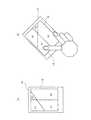
例えば、図9および図10に示すように、タッチパネルの有効/非有効領域を非均等に設定してもよいし、画面の使用向きに応じて装置上側に来る領域が常に所定のサイズの有効領域になるようにしてもよい。例えば、図9に示されるように有効/非有効領域が設定された装置10を天地逆転させると、領域(c)と領域(d)が上側に来て、領域(c)と領域(d)のサイズが狭くなる。 For example, as shown in FIGS. 9 and 10, the valid / invalid area of the touch panel may be set non-uniformly, or the area that is on the upper side of the device according to the use direction of the screen is always an effective area of a predetermined size. It may be made to become. For example, when the
また、有効/非有効領域の設定においてタッチパネルを直線で分割しなくてもよい。さらに、必ずしも2領域が有効とならなくてもよい。 Further, the touch panel may not be divided by a straight line in setting the effective / ineffective area. Furthermore, the two areas do not necessarily have to be effective.
加えて、タッチパネルの有効/非有効とする領域の形としては、図10(A)に示すように指の関節可動域に合わせて変形させてもよい。さらに、図10(A)に示される装置10を、図10(B)に示すように背面から見て右に45度回転させた場合に領域(a)と領域(b)を有効としたり、領域(a)と領域(c)を有効としたり、領域(a)と領域(b)と領域(c)を有効としたりしてもよい。 In addition, as the shape of the area to be valid / invalid of the touch panel, as shown in FIG. 10A, it may be deformed according to the range of motion of the finger joint. Further, when the
以上のように図5〜図10を参照して説明した発明態様においては、以下に記載するような効果を奏する。 As described above, the invention described with reference to FIGS. 5 to 10 has the following effects.
背面入力部であるタッチパネルの上側のみが有効に設定されているので、図7に示したように携帯端末装置を片手で持つときに握る指(中指、薬指、小指)のホールド場所が確保され、操作する指(人差し指)での操作が容易になる。 Since only the upper side of the touch panel, which is the back input unit, is set to be effective, a holding place for a finger (middle finger, ring finger, little finger) gripped when holding the mobile terminal device with one hand as shown in FIG. Operation with the operating finger (index finger) is facilitated.
特に、装置10を傾けた(表示画面を回転させた)場合でも、傾き検知部の出力に応じて、タッチパネルの上側の領域が常に有効領域に設定されるため、上記のように片手での操作が容易に行える。 In particular, even when the
以上説明した実施形態では、携帯端末装置としてスマートフォンを例に挙げたが、本発明はそれ以外の、携帯電話、オーディオプレイヤーなどの持ち運び可能な携帯端末装置に適用可能である。 In the embodiment described above, a smart phone is exemplified as the mobile terminal device. However, the present invention is applicable to other portable terminal devices such as a mobile phone and an audio player.
1 表示パネル
2 タッチパネル
3 アイコン
4 カーソル
5 指
6,7 指の動き
10 携帯端末装置
11 表示部
12 制御部
13 正面入力部(タッチパネル)
14 背面入力部(タッチパネル)
15 傾き検知部
16 人差し指DESCRIPTION OF SYMBOLS 1 Display panel 2 Touch panel 3 Icon 4 Cursor 5 Finger 6, 7
14 Rear input unit (touch panel)
15
Claims (4)
Translated fromJapanese表示パネルが搭載された第一の面と、
タッチパネルが搭載された、該第一の面とは反対側の第二の面とを備え、
前記携帯端末装置を使用する際の、前記第一の面の法線方向を回転軸とする前記携帯端末装置の回転角度に応じて、前記タッチパネルの全領域が有効領域と非有効領域に区分して設定されることを特徴とする携帯端末装置。A portable terminal device,
A first surface on which a display panel is mounted;
A second surface opposite to the first surface, on which a touch panel is mounted,
When using the mobile terminal device, the entire area of the touch panel is divided into an effective region and an ineffective region according to the rotation angle of the mobile terminal device with the normal direction of the first surface as the rotation axis. The portable terminal device is characterized by being set as follows.
Priority Applications (1)
| Application Number | Priority Date | Filing Date | Title |
|---|---|---|---|
| JP2012026261AJP2013165334A (en) | 2012-02-09 | 2012-02-09 | Mobile terminal device |
Applications Claiming Priority (1)
| Application Number | Priority Date | Filing Date | Title |
|---|---|---|---|
| JP2012026261AJP2013165334A (en) | 2012-02-09 | 2012-02-09 | Mobile terminal device |
Publications (1)
| Publication Number | Publication Date |
|---|---|
| JP2013165334Atrue JP2013165334A (en) | 2013-08-22 |
Family
ID=49176459
Family Applications (1)
| Application Number | Title | Priority Date | Filing Date |
|---|---|---|---|
| JP2012026261APendingJP2013165334A (en) | 2012-02-09 | 2012-02-09 | Mobile terminal device |
Country Status (1)
| Country | Link |
|---|---|
| JP (1) | JP2013165334A (en) |
Cited By (4)
| Publication number | Priority date | Publication date | Assignee | Title |
|---|---|---|---|---|
| JP2015106173A (en)* | 2013-11-28 | 2015-06-08 | 京セラ株式会社 | Electronics |
| JP2017537388A (en)* | 2014-10-30 | 2017-12-14 | 楽天株式会社 | Alternative gesture mode and system and method for implementing the mode |
| US10353567B2 (en) | 2013-11-28 | 2019-07-16 | Kyocera Corporation | Electronic device |
| JP2020149353A (en)* | 2019-03-13 | 2020-09-17 | 富士通コネクテッドテクノロジーズ株式会社 | Mobile terminal device, information processing method and information processing program |
Citations (5)
| Publication number | Priority date | Publication date | Assignee | Title |
|---|---|---|---|---|
| JPH0944143A (en)* | 1995-08-01 | 1997-02-14 | Toshiba Corp | Mobile information communication terminal device |
| JPH1139093A (en)* | 1997-07-15 | 1999-02-12 | Toshiba Corp | Information processing device and pointing device |
| JP2011028603A (en)* | 2009-07-28 | 2011-02-10 | Nec Casio Mobile Communications Ltd | Terminal device and program |
| US20110141045A1 (en)* | 2009-12-10 | 2011-06-16 | Samsung Electronics Co. Ltd. | Mobile terminal having multiple touch panels and operation method for the same |
| JP2012242851A (en)* | 2011-05-13 | 2012-12-10 | Lenovo Singapore Pte Ltd | Portable electronic device having touch screen and control method |
- 2012
- 2012-02-09JPJP2012026261Apatent/JP2013165334A/enactivePending
Patent Citations (5)
| Publication number | Priority date | Publication date | Assignee | Title |
|---|---|---|---|---|
| JPH0944143A (en)* | 1995-08-01 | 1997-02-14 | Toshiba Corp | Mobile information communication terminal device |
| JPH1139093A (en)* | 1997-07-15 | 1999-02-12 | Toshiba Corp | Information processing device and pointing device |
| JP2011028603A (en)* | 2009-07-28 | 2011-02-10 | Nec Casio Mobile Communications Ltd | Terminal device and program |
| US20110141045A1 (en)* | 2009-12-10 | 2011-06-16 | Samsung Electronics Co. Ltd. | Mobile terminal having multiple touch panels and operation method for the same |
| JP2012242851A (en)* | 2011-05-13 | 2012-12-10 | Lenovo Singapore Pte Ltd | Portable electronic device having touch screen and control method |
Cited By (5)
| Publication number | Priority date | Publication date | Assignee | Title |
|---|---|---|---|---|
| JP2015106173A (en)* | 2013-11-28 | 2015-06-08 | 京セラ株式会社 | Electronics |
| US10353567B2 (en) | 2013-11-28 | 2019-07-16 | Kyocera Corporation | Electronic device |
| JP2017537388A (en)* | 2014-10-30 | 2017-12-14 | 楽天株式会社 | Alternative gesture mode and system and method for implementing the mode |
| JP2020149353A (en)* | 2019-03-13 | 2020-09-17 | 富士通コネクテッドテクノロジーズ株式会社 | Mobile terminal device, information processing method and information processing program |
| JP7272831B2 (en) | 2019-03-13 | 2023-05-12 | Fcnt株式会社 | Portable terminal device, information processing method and information processing program |
Similar Documents
| Publication | Publication Date | Title |
|---|---|---|
| JP5189197B1 (en) | Portable information terminal | |
| JP5759660B2 (en) | Portable information terminal having touch screen and input method | |
| JP5661547B2 (en) | Portable terminal device and program | |
| US8775966B2 (en) | Electronic device and method with dual mode rear TouchPad | |
| JP3143462U (en) | Electronic device having switchable user interface and electronic device having convenient touch operation function | |
| CN104932809B (en) | Apparatus and method for controlling display panel | |
| RU2541852C2 (en) | Device and method of controlling user interface based on movements | |
| JP6181114B2 (en) | Input / output method and electronic equipment | |
| KR102212830B1 (en) | Method and apparatus for displaying picture on portable devices | |
| JP5855996B2 (en) | Terminal device | |
| JP5429627B2 (en) | Mobile terminal, mobile terminal operation method, and mobile terminal operation program | |
| JP5008707B2 (en) | Input display board and table | |
| US20170075453A1 (en) | Terminal and terminal control method | |
| JP5223784B2 (en) | Mobile terminal device | |
| JP2013165334A (en) | Mobile terminal device | |
| US11354031B2 (en) | Electronic apparatus, computer-readable non-transitory recording medium, and display control method for controlling a scroll speed of a display screen | |
| JP5628991B2 (en) | Display device, display method, and display program | |
| KR20100136289A (en) | Display Control Method of Mobile Terminal | |
| JP2014102557A (en) | Portable terminal | |
| JP5388310B2 (en) | Mobile terminal and information display method | |
| US20200033959A1 (en) | Electronic apparatus, computer-readable non-transitory recording medium, and display control method | |
| JP6367720B2 (en) | Information processing apparatus and program | |
| JP5969320B2 (en) | Mobile terminal device | |
| JP2013080273A (en) | Display input device and display method | |
| US20140191985A1 (en) | Method and device for controlling electronic device |
Legal Events
| Date | Code | Title | Description |
|---|---|---|---|
| RD04 | Notification of resignation of power of attorney | Free format text:JAPANESE INTERMEDIATE CODE: A7424 Effective date:20140515 | |
| A621 | Written request for application examination | Free format text:JAPANESE INTERMEDIATE CODE: A621 Effective date:20150114 | |
| A977 | Report on retrieval | Free format text:JAPANESE INTERMEDIATE CODE: A971007 Effective date:20150824 | |
| A131 | Notification of reasons for refusal | Free format text:JAPANESE INTERMEDIATE CODE: A131 Effective date:20150901 | |
| A02 | Decision of refusal | Free format text:JAPANESE INTERMEDIATE CODE: A02 Effective date:20160105 |