JP2013158591A - Smell generator - Google Patents
Smell generatorDownload PDFInfo
- Publication number
- JP2013158591A JP2013158591AJP2012024828AJP2012024828AJP2013158591AJP 2013158591 AJP2013158591 AJP 2013158591AJP 2012024828 AJP2012024828 AJP 2012024828AJP 2012024828 AJP2012024828 AJP 2012024828AJP 2013158591 AJP2013158591 AJP 2013158591A
- Authority
- JP
- Japan
- Prior art keywords
- odor
- smell
- subject
- ceramic
- generation
- Prior art date
- Legal status (The legal status is an assumption and is not a legal conclusion. Google has not performed a legal analysis and makes no representation as to the accuracy of the status listed.)
- Pending
Links
- 239000000919ceramicSubstances0.000claimsabstractdescription25
- 239000002184metalSubstances0.000claimsabstractdescription12
- 229910052751metalInorganic materials0.000claimsabstractdescription12
- 230000001678irradiating effectEffects0.000claimsdescription3
- 235000019645odorNutrition0.000description135
- 230000035943smellEffects0.000description25
- 230000007177brain activityEffects0.000description19
- 238000002595magnetic resonance imagingMethods0.000description18
- 210000004556brainAnatomy0.000description7
- 244000178870Lavandula angustifoliaSpecies0.000description6
- 235000010663Lavandula angustifoliaNutrition0.000description6
- 239000001102lavandula veraSubstances0.000description6
- 235000018219lavenderNutrition0.000description6
- 238000010586diagramMethods0.000description5
- 230000000694effectsEffects0.000description5
- QGZKDVFQNNGYKY-UHFFFAOYSA-NAmmoniaChemical compoundNQGZKDVFQNNGYKY-UHFFFAOYSA-N0.000description4
- OKTJSMMVPCPJKN-UHFFFAOYSA-NCarbonChemical compound[C]OKTJSMMVPCPJKN-UHFFFAOYSA-N0.000description4
- 238000010438heat treatmentMethods0.000description4
- 239000007788liquidSubstances0.000description4
- 239000002304perfumeSubstances0.000description4
- 239000002775capsuleSubstances0.000description3
- 235000013399edible fruitsNutrition0.000description3
- RYGMFSIKBFXOCR-UHFFFAOYSA-NCopperChemical compound[Cu]RYGMFSIKBFXOCR-UHFFFAOYSA-N0.000description2
- 229910021529ammoniaInorganic materials0.000description2
- 229910052802copperInorganic materials0.000description2
- 239000010949copperSubstances0.000description2
- 239000003205fragranceSubstances0.000description2
- 238000005259measurementMethods0.000description2
- 230000009965odorless effectEffects0.000description2
- 239000002245particleSubstances0.000description2
- 238000007781pre-processingMethods0.000description2
- 238000002360preparation methodMethods0.000description2
- 230000004936stimulating effectEffects0.000description2
- 241000251468ActinopterygiiSpecies0.000description1
- 235000005979Citrus limonNutrition0.000description1
- 244000131522Citrus pyriformisSpecies0.000description1
- LFQSCWFLJHTTHZ-UHFFFAOYSA-NEthanolChemical compoundCCOLFQSCWFLJHTTHZ-UHFFFAOYSA-N0.000description1
- 125000002066L-histidyl groupChemical group[H]N1C([H])=NC(C([H])([H])[C@](C(=O)[*])([H])N([H])[H])=C1[H]0.000description1
- 240000008790Musa x paradisiacaSpecies0.000description1
- 235000018290Musa x paradisiacaNutrition0.000description1
- 238000005481NMR spectroscopyMethods0.000description1
- 235000012970cakesNutrition0.000description1
- 238000004140cleaningMethods0.000description1
- 235000009508confectioneryNutrition0.000description1
- 230000008602contractionEffects0.000description1
- 239000002781deodorant agentSubstances0.000description1
- 230000001877deodorizing effectEffects0.000description1
- 235000019688fishNutrition0.000description1
- 235000013305foodNutrition0.000description1
- 238000002599functional magnetic resonance imagingMethods0.000description1
- 235000013372meatNutrition0.000description1
- 239000000843powderSubstances0.000description1
- 238000003825pressingMethods0.000description1
- 230000029058respiratory gaseous exchangeEffects0.000description1
- 239000004065semiconductorSubstances0.000description1
- 239000007921spraySubstances0.000description1
- 239000000126substanceSubstances0.000description1
- 230000001360synchronised effectEffects0.000description1
- 235000013311vegetablesNutrition0.000description1
- 238000005406washingMethods0.000description1
- 239000002351wastewaterSubstances0.000description1
Images


Landscapes
- Disinfection, Sterilisation Or Deodorisation Of Air (AREA)
Abstract
Description
Translated fromJapanese本発明は、におい発生装置に関する。 The present invention relates to an odor generating apparatus.
従来のにおい発生装置として、におい発生部材を加熱する加熱手段が知られている。また、所定のにおいの分子が印刷されている手のひらサイズのカードに指で圧力を加え、これによって、上記カードから所定のにおいを押し出し、においを発生する(たとえば、非特許文献1参照)。つまり、人が自分の指で直接、操作することによってにおいを発生させている。 As a conventional odor generating device, a heating means for heating an odor generating member is known. Further, pressure is applied by a finger to a palm-sized card on which molecules of a predetermined odor are printed, thereby pushing out a predetermined odor from the card and generating an odor (see, for example, Non-Patent Document 1). That is, a smell is generated when a person directly operates with his / her finger.
しかし、従来の加熱によるにおい発生装置は、加熱の指令を出してからにおいが実際に出るまでに時間がかかり、応答が遅いという問題がある。また、従来のにおいの分子を印刷してあるカードに指で圧力を加えてにおいを発生する場合、においの発生タイミングを外部から任意に制御することが困難であるという問題がある。 However, the conventional heating odor generating apparatus has a problem that it takes a long time from when the heating command is issued until the odor is actually emitted, and the response is slow. In addition, when a smell is generated by applying pressure with a finger to a conventional card on which odor molecules are printed, there is a problem that it is difficult to arbitrarily control the odor generation timing from the outside.
本発明は、におい発生の指令を出してから実際ににおいが発生するまでの応答が早く、また、においの発生タイミングを外部から任意に制御することが容易であるにおい発生装置を提供することを目的とする。 It is an object of the present invention to provide an odor generating apparatus that has a quick response from when an odor generation command is issued until an actual odor is generated, and that it is easy to arbitrarily control the odor generation timing from the outside. Objective.
本発明は、におい発生部材を振動させるセラミックまたは非磁性金属と、上記におい発生部材を振動させるために上記セラミックまたは非磁性金属の振動を制御する制御手段とを有することを特徴とするにおい発生装置である。 The present invention includes a ceramic or nonmagnetic metal that vibrates an odor generating member, and a control unit that controls vibration of the ceramic or nonmagnetic metal to vibrate the odor generating member. It is.
また、本発明は、におい発生部材にレーザーを照射するレーザー照射手段と、上記レーザーをパルス的に発生させるように上記レーザー照射手段を制御するレーザー照射制御手段とを有することを特徴とするにおい発生装置である。 The present invention also includes a laser irradiation means for irradiating the odor generating member with a laser, and a laser irradiation control means for controlling the laser irradiation means so as to generate the laser in a pulsed manner. Device.
本発明によれば、におい発生の指令を出してから実際ににおいが発生するまでの応答が早く、また、においの発生タイミングを外部から任意に制御することが容易であるという効果を奏する。 According to the present invention, there is an effect that the response from the generation of the odor generation command to the actual generation of the odor is quick, and it is easy to arbitrarily control the odor generation timing from the outside.
発明を実施するための形態は、次の実施例である。 The mode for carrying out the invention is the following embodiment.
図1は、本発明の実施例1であるにおい発生装置11を示す図である。 FIG. 1 is a diagram showing an odor generating apparatus 11 that is
におい発生装置11は、セラミック111と、におい発生部材112と、スイッチ手段113と、交流電源114と、制御手段115とを有する。 The odor generating device 11 includes a ceramic 111, an odor generating member 112, a switch unit 113, an AC power source 114, and a control unit 115.
セラミック111は、図示しない端子を有し、この端子に、導線、スイッチ手段113を介して、交流電源114が接続されている。 The ceramic 111 has a terminal (not shown), and an AC power supply 114 is connected to the terminal via a conductive wire and switch means 113.
におい発生部材112は、それを振動すると、所定のにおいが発生するものである。たとえば、アンモニア、アルコール、香水等の液体、これらの液体が封入されているカプセル、果実の皮、実等が考えられる。 The odor generating member 112 generates a predetermined odor when it is vibrated. For example, liquids such as ammonia, alcohol, perfume, capsules in which these liquids are sealed, fruit peels, fruits, and the like are conceivable.
スイッチ手段113は、半導体スイッチ等で構成され、制御手段115によって、そのオン、オフが制御されている。スイッチ手段113がオンしていると、交流電源114がセラミック111に印加される。なお、スイッチ手段113が短時間でオン、オフを繰り返すと、交流電源114の代わりに直流電源を使用しても、セラミック111に交流電圧を印加することができる。 The switch means 113 is composed of a semiconductor switch or the like, and its on / off is controlled by the control means 115. When the switch means 113 is on, the AC power supply 114 is applied to the ceramic 111. If the switch means 113 is repeatedly turned on and off in a short time, an AC voltage can be applied to the ceramic 111 even if a DC power supply is used instead of the AC power supply 114.
次に、におい発生装置11の動作について説明する。 Next, the operation of the odor generating device 11 will be described.
まず、図1に示すように、セラミック111の上に、におい発生部材112を載置し、制御手段115がスイッチ手段113をオンすると、交流電圧がセラミック111に印加され、印加されている間中、セラミック111が振動する。この振動の周期は、交流電源114の周波数と同じである。この振動によって、におい発生部材112も振動し、におい発生部材112が噴霧状、粉末状に変化し、またはにおい発生部材112を構成する(または包んでいる)カプセルが破壊され、封入されていた液体、気体が発散し、これによって、特有のにおいが発生すると考えられる。 First, as shown in FIG. 1, when the odor generating member 112 is placed on the ceramic 111 and the control means 115 turns on the switch means 113, an alternating voltage is applied to the ceramic 111, and while the voltage is being applied. The ceramic 111 vibrates. The period of this vibration is the same as the frequency of the AC power source 114. Due to this vibration, the odor generating member 112 also vibrates, the odor generating member 112 changes to a spray or powder, or the capsule constituting (or enveloping) the odor generating member 112 is destroyed and the encapsulated liquid It is thought that gas diverges and a specific smell is generated.
そして、制御手段115がスイッチ手段113をオフすると、セラミック111が振動を停止し、におい発生部材112からのにおい発生が停止される。 When the control means 115 turns off the switch means 113, the ceramic 111 stops oscillating and the odor generation from the odor generating member 112 is stopped.
上記のように、におい発生装置11は、制御手段115を介して、におい発生の指令を出してから実際ににおいが発生するまでの応答が早く、また、においの発生タイミングを、制御手段115を介して、におい発生装置11の外部から任意に制御することが容易である。 As described above, the odor generating device 11 has a quick response from the issuing of the odor generation command through the control means 115 to the actual generation of the odor, and the odor generation timing is controlled by the control means 115. Therefore, it is easy to arbitrarily control from the outside of the odor generating device 11.
なお、セラミックの代わりに、音叉を構成する金属であって、銅等の非磁性金属を使用するようにしてもよい。音叉を構成する金属であって、銅等の非磁性金属に交流電圧を印加すると、上記音叉を構成する非磁性金属が振動する。 In place of ceramic, a metal constituting the tuning fork and a nonmagnetic metal such as copper may be used. When an AC voltage is applied to a non-magnetic metal such as copper, which is a metal constituting the tuning fork, the non-magnetic metal constituting the tuning fork vibrates.
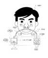
図2は、におい発生装置11で発生したにおいを被験者Pに嗅がせている状態を示す図である。 FIG. 2 is a diagram illustrating a state in which the subject P smells the odor generated by the odor generating device 11.
なお、以下の記載において、においは単独では存在せず、においの分子が空気に含まれ、これが、供給管12、開口H1、H2を通過し、被験者Pの鼻の内部に達し、被験者の呼気とともに、排出管13を介して、吸引装置14に達するが、におい分子が含まれている空気を、説明の都合上、単に「におい」と表現する。 In the following description, the odor does not exist alone, and the odor molecule is contained in the air, passes through the
図3は、図2に示すにおい処理装置10を使用し、におい発生装置11で発生したにおいを被験者Pに嗅がせて脳の活動状態を測定する脳の活動状態測定装置100を示す図である。 FIG. 3 is a diagram showing a brain activity state measurement apparatus 100 that uses the
一般に、f−MRI(fanctional MRI)は、被験者に刺激を与える刺激装置との同期を取って、脳の断層データを取得するMRIであり、脳の活動状態測定装置100は、上記刺激装置として嗅覚刺激を行うものである。また、MRI20は、μ秒オーダーで1枚の断層データを取得する。 In general, f-MRI (functional MRI) is an MRI that acquires brain tomographic data in synchronization with a stimulating device that gives a stimulus to a subject. The brain activity state measuring device 100 is an olfactory sense as the stimulating device. It is a stimulus. Further, the
におい処理装置10は、におい発生装置11と、供給管12と、排出管13と、吸引装置14とを有する。 The
におい処理装置10に供給管12が接続され、供給管12に開口H1、H2が設けられ、開口H1、H2が被験者Pの鼻に挿入(または配置)されている。 A
供給管12は、MRI20における被験者Pの鼻の位置に所定のにおいを供給する経路を形成する管であって、非磁性の管である。つまり、供給管12は、におい発生装置11から、MRI20における被験者Pの鼻の位置に至る経路に設けられている管である。 The
また、供給管12は、入口端121と、開口H1 、H2とを有する。排出管13は、出口端131を有する。 The
入口端121は、供給管12の一端であり、におい発生装置11の筐体に接続されている。 The inlet end 121 is one end of the
開口H1 、H2は、供給管12の途中に設けられ、開口H1 、H2の近傍は突起状を有し、その先端がやや細い断面台形状を有し、被験者Pの鼻に挿入される。なお、上記突起状の先端部分に穴が設けられ、この穴を介して、供給管12に存在するにおい成分が被験者Pの鼻に入り、被験者Pがそのにおいを嗅覚で検知する。また、上記穴を介して、被験者Pの呼気が鼻から吸収される。また、開口H1、H2の近傍の形状は、曲面を有するようにし、たとえば、半球状(断面が半円状)であってもよい。 The openings H1 and H2 are provided in the middle of the
出口端131は、排出管13の他端であり、吸引装置14に接続されている。 The outlet end 131 is the other end of the discharge pipe 13 and is connected to the
吸引装置14は、ポンプ機能を有し、供給管12に存在しているにおい成分と、被験者Pの呼気とを吸引する。また、吸引装置14の内部に活性炭141等のにおい粒子吸着部材が設けられている。活性炭141は、被験者の鼻の近傍に存在している所定のにおいを消去する消臭手段であり、上記所定のにおいを吸着するにおい粒子吸着部材の例である。 The
脳の活動状態測定装置100は、図3に示すように、準備室R1と、MRI室R2とを有する。準備室R1には、におい処理装置10と、記憶装置30と、表示装置40と、制御装置50とが設けられている。 As shown in FIG. 3, the brain activity state measuring apparatus 100 has a preparation room R1 and an MRI room R2. In the preparation room R1, an
MRI室R2には、MRI20が設けられ、この中に被験者Pが横たわっている。なお、MRI20は、核磁気共鳴または磁気共鳴ともいわれるものである。 The MRI room R2 is provided with an
記憶装置30は、におい処理装置10が発生しているにおいのIDであるにおいIDの情報を、におい処理装置10または制御装置50から受信し、記憶する。また、記憶装置30は、におい処理装置10が発生したにおいを被験者Pが嗅いだときにおける脳の活動状態のデータをMRI20から受信し、この脳の活動状態のデータと対応するにおいIDとを記憶する。 The
表示装置40は、記憶装置30に記憶されている脳の活動状態のデータに対応する脳の断層写真を表示する。 The
制御装置50は、CPU等で構成され、脳の活動状態測定装置100の全体を制御する。また、制御装置50は、被験者Pの呼吸に同期して、被験者Pの脳の活動状態のデータを、MRI20に取得させる制御手段である。さらに、制御装置50は、被験者Pの吸気に同期して、被験者Pの脳の活動状態のデータを、MRI20に取得させる制御手段である。この場合、被験者Pの吸気の開始に同期して、被験者Pの脳の活動状態のデータを、MRI20に取得させることが望ましいが、吸気の開始から終了の間の所定のタイミングに同期して、被験者Pの脳の活動状態のデータを、MRI20に取得させるようにしてもよい。 The
そして、制御装置50は、被験者Pの心拍に同期して、被験者Pの脳の活動状態のデータを、MRI20に取得させる制御手段である。この場合、被験者Pの心臓の収縮に同期して、被験者Pの脳の活動状態のデータを、MRI20に取得させることが望ましい。 The
また、においを被験者Pに嗅がせる場合、健常者がにおいを嗅ぎ分ける程度の時間のみ、被験者Pの鼻に上記においを供給する。つまり、健常者がにおいを嗅ぎ分ける程度の時間のみ、におい発生装置11においてにおいを発生し、また、上記時間に多少の時間を加えた時間、吸引装置14がにおいを吸引する。 In addition, when the subject P smells the odor, the odor is supplied to the nose of the subject P only during a period when the healthy person sniffs the odor. In other words, the odor generating device 11 generates odor only during a period of time when the healthy person sniffs the odor, and the
次に、上記実施例の動作について説明する。 Next, the operation of the above embodiment will be described.
図4は、上記実施例における制御装置50の動作を示すフローチャートである。 FIG. 4 is a flowchart showing the operation of the
まず、S0で、前処理を実行する。つまり、被験者Pの心を静めるために、たとえばラベンダーのにおいを、供給管12を介して開口H1、H2に送り、その後に、空気洗浄する(無臭の空気を開口H1 、H2に送る)。開口H1 、H2にラベンダーのにおい、無臭の空気を送る場合、供給管12の入口端121をラベンダー収納ケース(図示せず)、無臭の空気収納ケース(図示せず)に接続し、吸引装置14に吸引させ、空気洗浄が終了すると、吸引を終了する。なお、上記前処理において、ラベンダーの代わりに他の芳香を使用するようにしてもよい。 First, pre-processing is executed at S0. That is, in order to calm the mind of the subject P, for example, the smell of lavender is sent to the openings H1 and H2 through the
そして、S1で、制御装置50が、制御手段115を介してスイッチ手段113を制御し、におい処理装置10におけるセラミック111に通電し、セラミック111が振動を開始し、におい発生部材112がにおいを発生する。S2で、吸引装置14に吸引を開始させる。S3で、吸引開始から第1の所定時間が経過した後に、MRI20に脳の活動状態のデータ(断層写真)を出力させる。つまり、所定のにおいを被験者Pが嗅いでいる動作と、脳の活動状態のデータを出力させる動作(脳の断層写真を撮影する動作)とを同期させる。 In S1, the
S4で、発生したにおいのIDであるにおいIDと、これに対応する脳の活動状態のデータとを記憶装置30に記憶させる。S5で、吸引開始から第2の所定時間が経過した後に、セラミック111への通電を終了し、セラミック111の振動を停止する。 In S4, the odor ID, which is the ID of the generated odor, and the brain activity state data corresponding thereto are stored in the
その後に、S6で、他のにおいについて脳の活動状態のデータを取得する必要がないと判断されれば、S7で、吸引装置14に吸引を終了させる。 Thereafter, if it is determined in S6 that it is not necessary to acquire brain activity state data for other odors, the
上記実施例によれば、制御手段115の制御によってにおいが発生するので、においを発生するタイミングを一定にすることが可能であり、また、においの発生タイミングを任意に制御することができ、したがって、においに対する被験者Pの脳の活動状態のデータの正確性を担保することができる。 According to the above embodiment, since the odor is generated by the control of the control means 115, the odor generation timing can be made constant, and the odor generation timing can be arbitrarily controlled. The accuracy of the data of the activity state of the brain of the subject P with respect to the odor can be ensured.
一方、S6で、他のにおいについて脳の活動状態のデータを取得する必要があると判断されれば、S8で、異なるにおい発生部材112について、上記ステップS1〜S5の処理を実行し、S6に戻る。たとえば、におい処理装置10が、複数のにおい発生装置11を設け、その中に設置されるにおい発生部材112を互いに異なるものにする。たとえば、1つ目のにおい発生部材112は、レモンのにおいを発生する部材であり、2つ目のにおい発生部材112は、バナナのにおいを発生する部材であるとする。においとして、果物のにおいだけでなく、ラベンダー等の花のにおい、酒のにおい、香水のにおい、アンモニア等の薬品のにおい等、種々のにおいを用意するようにしてもよい。 On the other hand, if it is determined in S6 that it is necessary to acquire brain activity state data for other odors, the processing in steps S1 to S5 is executed for different odor generating members 112 in S8. Return. For example, the
このように複数のにおいを使用すれば、複数のにおいのそれぞれを被験者Pが嗅いだときにおける脳の活動状態のデータを、個別に取得することができる。 If a plurality of smells are used in this way, data on the brain activity state when the subject P sniffs each of the plurality of smells can be individually acquired.
なお、複数のにおいについて測定する場合、前処理(S0)と同じ処理を、新たなにおいを発生する前(S1の前)に毎回、実行するようにしてもよい。この場合、新たなにおいを発生する前(S1の前)に、ラベンダーのにおいを被験者Pに嗅がせずに、空気洗浄のみを実行するようにしてもよい。 When measuring a plurality of odors, the same processing as the preprocessing (S0) may be executed every time before a new odor is generated (before S1). In this case, it is possible to perform only air washing without generating a lavender odor to the subject P before generating a new odor (before S1).
新たな香水を評価する際に、上記実施例を利用することができる。 When evaluating a new perfume, the above examples can be used.
また、MRI20の代わりに、MEG(脳磁計)を使用するようにしてもよい。 Further, instead of the
図5は、本発明の実施例2であるにおい発生装置11aを示す図である。 FIG. 5 is a diagram showing an odor generating apparatus 11a that is
におい発生装置11aは、セラミック111a、111bと、におい発生部材112と、スイッチ手段113と、交流電源114と、制御手段115とを有する。なお、図1に示す部材と同一の部材には同一の符号を付してある。におい発生装置11aは、セラミックが2つ設けられ、これら2つのセラミック111a、111bの間に、におい発生部材112が挟まれている。これによって、セラミック111a、111bの振動をにおい発生部材112に確実に伝達するので、においが確実にかつ多量に発生する。 The odor generating device 11a includes ceramics 111a and 111b, an odor generating member 112, a switch unit 113, an AC power source 114, and a control unit 115. In addition, the same code | symbol is attached | subjected to the member same as the member shown in FIG. The odor generating device 11a is provided with two ceramics, and the odor generating member 112 is sandwiched between the two ceramics 111a and 111b. Accordingly, the vibrations of the ceramics 111a and 111b are reliably transmitted to the odor generating member 112, so that the odor is surely generated in a large amount.
におい発生装置11aにおいても、制御手段115を介して、におい発生の指令を出してから実際ににおいが発生するまでの応答が早く、また、においの発生タイミングを、制御手段115を介して、におい発生装置11aの外部から任意に制御することが容易である。 Also in the odor generating device 11a, the response from the generation of the odor generation command through the control means 115 to the actual odor generation is quick, and the odor generation timing is controlled through the control means 115. It is easy to arbitrarily control from the outside of the generator 11a.
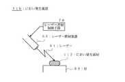
図6は、本発明の実施例3であるにおい発生装置11bを示す図である。 FIG. 6 is a diagram showing an odor generating device 11b that is
におい発生装置11bは、におい発生部材112と、レーザー照射装置60と、レーザー照射制御手段70と、台80とを有する。 The odor generating device 11b includes an odor generating member 112, a laser irradiation device 60, laser irradiation control means 70, and a table 80.
レーザー照射装置60は、におい発生部材112にレーザーを照射する手段である。 The laser irradiation device 60 is means for irradiating the odor generating member 112 with a laser.
レーザー照射制御手段70は、レーザー照射装置60がパルス的にレーザーを発生するように、レーザー照射手段70を制御する手段である。 The laser irradiation control means 70 is a means for controlling the laser irradiation means 70 so that the laser irradiation apparatus 60 generates a laser in a pulse manner.
次に、実施例3の動作について説明する。 Next, the operation of the third embodiment will be described.
まず、図6に示すように、台80の上に、におい発生部材112を載置し、レーザー照射制御手段70によってレーザー照射装置60がパルス的にレーザーを発生し、この発生したレーザーをにおい発生部材112に照射する。この照射によって、におい発生部材112が噴霧状、粉末状に変化し、または上記カプセルが破壊され、封入されていた液体、気体が発散し、これによって、特有のにおいが発生すると考えられる。 First, as shown in FIG. 6, the odor generating member 112 is placed on a table 80, and the laser irradiation control means 70 causes the laser irradiation device 60 to generate a laser pulse, and the generated laser generates an odor. The member 112 is irradiated. By this irradiation, the odor generating member 112 is changed to a sprayed state or a powdered state, or the capsule is broken, and the encapsulated liquid or gas is diffused, thereby generating a specific odor.
そして、レーザー照射制御手段70がレーザー照射装置60によるレーザー照射を停止すると、におい発生部材112からのにおい発生が停止される。 And when the laser irradiation control means 70 stops the laser irradiation by the laser irradiation apparatus 60, the generation of the odor from the odor generating member 112 is stopped.
におい発生装置11bにおいて、レーザー照射制御手段70を介して、におい発生の指令を出してから実際ににおいが発生するまでの応答が早く、また、においの発生タイミングを、レーザー照射制御手段70を介して、におい発生装置11bの外部から任意に制御することが容易である。 In the odor generating device 11b, the response from the generation of the odor generation command through the laser irradiation control means 70 to the actual generation of the odor is quick, and the odor generation timing is determined via the laser irradiation control means 70. Thus, it is easy to arbitrarily control from the outside of the odor generating device 11b.
上記各実施例を使用する場合、におい発生部材112の成分を特定すれば、様々な分野において、においの標準を設定することができる。たとえば、消臭剤、芳香剤、香水等を製造する場合におけるにおいの標準を設定することができる。また、菓子、ケーキ、肉、魚、野菜、各種料理等の食品におけるにおいの標準を設定することができる。また、車の排気ガスの測定、工場廃水等の公害の元となるにおいの標準を設定することができる。 When each of the above embodiments is used, the odor standard can be set in various fields by specifying the components of the odor generating member 112. For example, it is possible to set an odor standard when producing deodorants, fragrances, perfumes and the like. It is also possible to set odor standards for foods such as confectionery, cakes, meat, fish, vegetables and various dishes. In addition, it is possible to set an odor standard that is a source of pollution such as vehicle exhaust gas measurement and factory wastewater.
11、11a、11b…におい発生装置、
111、111a、111b…セラミック、
112…におい発生部材、
113…スイッチ手段、
114…交流電源、
115…制御手段、
60…レーザー照射装置、
70…レーザー照射制御手段。11, 11a, 11b ... odor generating device,
111, 111a, 111b ... ceramic,
112 ... Odor generating member,
113 ... Switch means,
114 ... AC power supply,
115 ... control means,
60 ... Laser irradiation device,
70: Laser irradiation control means.
Claims (3)
Translated fromJapanese上記におい発生部材を振動させるために上記セラミックまたは非磁性金属の振動を制御する制御手段と;
を有することを特徴とするにおい発生装置。Ceramic or non-magnetic metal that vibrates the odor generating member;
Control means for controlling the vibration of the ceramic or non-magnetic metal to vibrate the odor generating member;
An odor generating device comprising:
上記制御手段は、上記セラミックまたは非磁性金属に交流電圧を印加する手段であることを特徴とするにおい発生装置。In claim 1,
The odor generator according to claim 1, wherein the control means is means for applying an AC voltage to the ceramic or nonmagnetic metal.
上記レーザーをパルス的に発生させるように上記レーザー照射手段を制御するレーザー照射制御手段と;
を有することを特徴とするにおい発生装置。Laser irradiation means for irradiating the odor generating member with laser;
Laser irradiation control means for controlling the laser irradiation means so as to generate the laser in a pulsed manner;
An odor generating device comprising:
Priority Applications (1)
| Application Number | Priority Date | Filing Date | Title |
|---|---|---|---|
| JP2012024828AJP2013158591A (en) | 2012-02-08 | 2012-02-08 | Smell generator |
Applications Claiming Priority (1)
| Application Number | Priority Date | Filing Date | Title |
|---|---|---|---|
| JP2012024828AJP2013158591A (en) | 2012-02-08 | 2012-02-08 | Smell generator |
Publications (1)
| Publication Number | Publication Date |
|---|---|
| JP2013158591Atrue JP2013158591A (en) | 2013-08-19 |
Family
ID=49171334
Family Applications (1)
| Application Number | Title | Priority Date | Filing Date |
|---|---|---|---|
| JP2012024828APendingJP2013158591A (en) | 2012-02-08 | 2012-02-08 | Smell generator |
Country Status (1)
| Country | Link |
|---|---|
| JP (1) | JP2013158591A (en) |
Cited By (1)
| Publication number | Priority date | Publication date | Assignee | Title |
|---|---|---|---|---|
| CN110738898A (en)* | 2019-10-28 | 2020-01-31 | 西南大学 | an odor diffuser |
Citations (8)
| Publication number | Priority date | Publication date | Assignee | Title |
|---|---|---|---|---|
| JPH04279171A (en)* | 1991-02-27 | 1992-10-05 | Furuno Electric Co Ltd | Scent generator |
| JPH05317401A (en)* | 1992-05-15 | 1993-12-03 | Matsushita Electric Ind Co Ltd | Fragrance generator |
| JPH06509730A (en)* | 1991-08-16 | 1994-11-02 | ザ リージェンツ オヴ ザ ユニヴァーシティ オヴ カリフォルニア | Measurement of brain activity including characteristics of brain lesions using electroencephalography |
| JPH0747059A (en)* | 1993-08-06 | 1995-02-21 | Hitachi Ltd | Inspection device using magnetic resonance |
| JP2002524206A (en)* | 1998-09-10 | 2002-08-06 | センシート インコーポレイテッド | Method and apparatus for odor regeneration |
| JP2005525897A (en)* | 2002-05-13 | 2005-09-02 | エス.シー. ジョンソン アンド サン、インコーポレイテッド | Harmonious fragrance, light and sound generation |
| JP2008504930A (en)* | 2004-06-30 | 2008-02-21 | エス.シー. ジョンソン アンド サン、インコーポレイテッド | Electromechanical device for distributing multiple volatile substances with a single distribution mechanism and cartridge for holding multiple containers |
| JP2010119562A (en)* | 2008-11-19 | 2010-06-03 | Sanyo Electric Co Ltd | Relaxation float for bathtub |
- 2012
- 2012-02-08JPJP2012024828Apatent/JP2013158591A/enactivePending
Patent Citations (8)
| Publication number | Priority date | Publication date | Assignee | Title |
|---|---|---|---|---|
| JPH04279171A (en)* | 1991-02-27 | 1992-10-05 | Furuno Electric Co Ltd | Scent generator |
| JPH06509730A (en)* | 1991-08-16 | 1994-11-02 | ザ リージェンツ オヴ ザ ユニヴァーシティ オヴ カリフォルニア | Measurement of brain activity including characteristics of brain lesions using electroencephalography |
| JPH05317401A (en)* | 1992-05-15 | 1993-12-03 | Matsushita Electric Ind Co Ltd | Fragrance generator |
| JPH0747059A (en)* | 1993-08-06 | 1995-02-21 | Hitachi Ltd | Inspection device using magnetic resonance |
| JP2002524206A (en)* | 1998-09-10 | 2002-08-06 | センシート インコーポレイテッド | Method and apparatus for odor regeneration |
| JP2005525897A (en)* | 2002-05-13 | 2005-09-02 | エス.シー. ジョンソン アンド サン、インコーポレイテッド | Harmonious fragrance, light and sound generation |
| JP2008504930A (en)* | 2004-06-30 | 2008-02-21 | エス.シー. ジョンソン アンド サン、インコーポレイテッド | Electromechanical device for distributing multiple volatile substances with a single distribution mechanism and cartridge for holding multiple containers |
| JP2010119562A (en)* | 2008-11-19 | 2010-06-03 | Sanyo Electric Co Ltd | Relaxation float for bathtub |
Cited By (1)
| Publication number | Priority date | Publication date | Assignee | Title |
|---|---|---|---|---|
| CN110738898A (en)* | 2019-10-28 | 2020-01-31 | 西南大学 | an odor diffuser |
Similar Documents
| Publication | Publication Date | Title |
|---|---|---|
| US11890535B2 (en) | System and method for generating olfactory stimuli | |
| US6712287B1 (en) | Programmable device for diffusing olfactory peaks | |
| US11351450B2 (en) | Systems and techniques for generating scent | |
| WO2019082836A1 (en) | Odor adjustment system, odor adjustment method, and program | |
| CN102680644B (en) | For measuring the method for the emotional reactions to olfactory stimulus | |
| JP2011512188A (en) | Fragrance dispenser | |
| KR101913729B1 (en) | Apparatus for manufacturing customized aroma perfume | |
| US20210121835A1 (en) | Nano emulsion process for scented liquids | |
| EP3972433A1 (en) | Generating aerosol using vibration and heating in a vaporizer device | |
| JP2013158591A (en) | Smell generator | |
| Lawless | Effects of odors on mood and behavior: aromatherapy and related effects | |
| JP2021525606A (en) | How to monitor the system that produces the droplet output and the wash | |
| JP7227550B2 (en) | Intestinal activity regulation device, intestinal activity regulation system, and intestinal activity regulation program | |
| JP5792437B2 (en) | Brain activity measurement device | |
| JP2016163633A (en) | Odor generation device, odor generation/deodorant device, device for investigating brain reaction to odor | |
| JP7454815B2 (en) | Volatile component supply device, volatile component supply method, and volatile component evaluation method | |
| JP2007054445A (en) | Perfume blowing control device and method | |
| JP3114717U (en) | Liquid atomizer | |
| KR20170064722A (en) | Method for activating olfactory function | |
| TW201922173A (en) | Dispenser | |
| JP2024528622A (en) | Methods for measuring responses to olfactory stimuli | |
| JP2001174371A (en) | Method and apparatus for generating fragrance for olfactometry | |
| JP2005030751A (en) | Air cleaner | |
| Lone et al. | OUTLINE AND IMPLEMENTATION OF A BIOMEDICAL SLEEP INDUCER. | |
| Zhou et al. | E-scent Coach: A Wearable Olfactory System to Guide Deep Breathing Synchronized with Yoga Postures |
Legal Events
| Date | Code | Title | Description |
|---|---|---|---|
| A621 | Written request for application examination | Free format text:JAPANESE INTERMEDIATE CODE: A621 Effective date:20150203 | |
| A977 | Report on retrieval | Free format text:JAPANESE INTERMEDIATE CODE: A971007 Effective date:20160127 | |
| A131 | Notification of reasons for refusal | Free format text:JAPANESE INTERMEDIATE CODE: A131 Effective date:20160205 | |
| A521 | Written amendment | Free format text:JAPANESE INTERMEDIATE CODE: A523 Effective date:20160404 | |
| A131 | Notification of reasons for refusal | Free format text:JAPANESE INTERMEDIATE CODE: A131 Effective date:20160422 | |
| A521 | Written amendment | Free format text:JAPANESE INTERMEDIATE CODE: A523 Effective date:20160621 | |
| A02 | Decision of refusal | Free format text:JAPANESE INTERMEDIATE CODE: A02 Effective date:20161007 |