JP2013158589A - Medical image diagnosis apparatus - Google Patents
Medical image diagnosis apparatusDownload PDFInfo
- Publication number
- JP2013158589A JP2013158589AJP2012024799AJP2012024799AJP2013158589AJP 2013158589 AJP2013158589 AJP 2013158589AJP 2012024799 AJP2012024799 AJP 2012024799AJP 2012024799 AJP2012024799 AJP 2012024799AJP 2013158589 AJP2013158589 AJP 2013158589A
- Authority
- JP
- Japan
- Prior art keywords
- power
- diagnostic apparatus
- medical image
- image diagnostic
- ray
- Prior art date
- Legal status (The legal status is an assumption and is not a legal conclusion. Google has not performed a legal analysis and makes no representation as to the accuracy of the status listed.)
- Pending
Links
Images


Classifications
- H—ELECTRICITY
- H04—ELECTRIC COMMUNICATION TECHNIQUE
- H04B—TRANSMISSION
- H04B5/00—Near-field transmission systems, e.g. inductive or capacitive transmission systems
- H04B5/70—Near-field transmission systems, e.g. inductive or capacitive transmission systems specially adapted for specific purposes
- H04B5/79—Near-field transmission systems, e.g. inductive or capacitive transmission systems specially adapted for specific purposes for data transfer in combination with power transfer
- A—HUMAN NECESSITIES
- A61—MEDICAL OR VETERINARY SCIENCE; HYGIENE
- A61B—DIAGNOSIS; SURGERY; IDENTIFICATION
- A61B6/00—Apparatus or devices for radiation diagnosis; Apparatus or devices for radiation diagnosis combined with radiation therapy equipment
- A61B6/54—Control of apparatus or devices for radiation diagnosis
- A61B6/548—Remote control of the apparatus or devices
- A—HUMAN NECESSITIES
- A61—MEDICAL OR VETERINARY SCIENCE; HYGIENE
- A61B—DIAGNOSIS; SURGERY; IDENTIFICATION
- A61B8/00—Diagnosis using ultrasonic, sonic or infrasonic waves
- A61B8/56—Details of data transmission or power supply
- H—ELECTRICITY
- H02—GENERATION; CONVERSION OR DISTRIBUTION OF ELECTRIC POWER
- H02J—CIRCUIT ARRANGEMENTS OR SYSTEMS FOR SUPPLYING OR DISTRIBUTING ELECTRIC POWER; SYSTEMS FOR STORING ELECTRIC ENERGY
- H02J50/00—Circuit arrangements or systems for wireless supply or distribution of electric power
- H02J50/10—Circuit arrangements or systems for wireless supply or distribution of electric power using inductive coupling
- H02J50/12—Circuit arrangements or systems for wireless supply or distribution of electric power using inductive coupling of the resonant type
- H—ELECTRICITY
- H02—GENERATION; CONVERSION OR DISTRIBUTION OF ELECTRIC POWER
- H02J—CIRCUIT ARRANGEMENTS OR SYSTEMS FOR SUPPLYING OR DISTRIBUTING ELECTRIC POWER; SYSTEMS FOR STORING ELECTRIC ENERGY
- H02J50/00—Circuit arrangements or systems for wireless supply or distribution of electric power
- H02J50/40—Circuit arrangements or systems for wireless supply or distribution of electric power using two or more transmitting or receiving devices
- H02J50/402—Circuit arrangements or systems for wireless supply or distribution of electric power using two or more transmitting or receiving devices the two or more transmitting or the two or more receiving devices being integrated in the same unit, e.g. power mats with several coils or antennas with several sub-antennas
- H—ELECTRICITY
- H02—GENERATION; CONVERSION OR DISTRIBUTION OF ELECTRIC POWER
- H02J—CIRCUIT ARRANGEMENTS OR SYSTEMS FOR SUPPLYING OR DISTRIBUTING ELECTRIC POWER; SYSTEMS FOR STORING ELECTRIC ENERGY
- H02J7/00—Circuit arrangements for charging or depolarising batteries or for supplying loads from batteries
- H02J7/0029—Circuit arrangements for charging or depolarising batteries or for supplying loads from batteries with safety or protection devices or circuits
- H02J7/00302—Overcharge protection
- H—ELECTRICITY
- H04—ELECTRIC COMMUNICATION TECHNIQUE
- H04B—TRANSMISSION
- H04B5/00—Near-field transmission systems, e.g. inductive or capacitive transmission systems
- H04B5/20—Near-field transmission systems, e.g. inductive or capacitive transmission systems characterised by the transmission technique; characterised by the transmission medium
- H04B5/24—Inductive coupling
- H—ELECTRICITY
- H02—GENERATION; CONVERSION OR DISTRIBUTION OF ELECTRIC POWER
- H02J—CIRCUIT ARRANGEMENTS OR SYSTEMS FOR SUPPLYING OR DISTRIBUTING ELECTRIC POWER; SYSTEMS FOR STORING ELECTRIC ENERGY
- H02J2310/00—The network for supplying or distributing electric power characterised by its spatial reach or by the load
- H02J2310/10—The network having a local or delimited stationary reach
- H02J2310/20—The network being internal to a load
- H02J2310/23—The load being a medical device, a medical implant, or a life supporting device
Landscapes
- Engineering & Computer Science (AREA)
- Health & Medical Sciences (AREA)
- Life Sciences & Earth Sciences (AREA)
- Computer Networks & Wireless Communication (AREA)
- Medical Informatics (AREA)
- Power Engineering (AREA)
- Public Health (AREA)
- Surgery (AREA)
- Nuclear Medicine, Radiotherapy & Molecular Imaging (AREA)
- Physics & Mathematics (AREA)
- Pathology (AREA)
- Radiology & Medical Imaging (AREA)
- Biomedical Technology (AREA)
- Heart & Thoracic Surgery (AREA)
- Molecular Biology (AREA)
- Veterinary Medicine (AREA)
- Animal Behavior & Ethology (AREA)
- General Health & Medical Sciences (AREA)
- Biophysics (AREA)
- Signal Processing (AREA)
- High Energy & Nuclear Physics (AREA)
- Optics & Photonics (AREA)
- Apparatus For Radiation Diagnosis (AREA)
- Magnetic Resonance Imaging Apparatus (AREA)
- Charge And Discharge Circuits For Batteries Or The Like (AREA)
Abstract
Description
Translated fromJapaneseこの発明の実施形態は医用画像診断装置に関する。 Embodiments described herein relate generally to a medical image diagnostic apparatus.
医用画像診断装置は、被検体内からの信号を受信して被検体の生体情報を取得するものである。医用画像診断装置には、装置本体と、これに連係して動作するデバイスとを有するものがある。このような医用画像診断装置としては、X線診断装置、MRI(Magnetic Resonance Imaging)装置、超音波診断装置などがある。X線診断装置の当該デバイスの例として無線X線検出器(ワイヤレスFPD(Flat Panel Detector))がある。MRI装置の当該デバイスの例としてRFコイルユニットがある。超音波診断装置の当該デバイスの例として超音波プローブがある。 A medical image diagnostic apparatus receives a signal from within a subject and acquires biological information of the subject. Some medical image diagnostic apparatuses include an apparatus main body and a device that operates in conjunction with the apparatus main body. Examples of such a medical image diagnostic apparatus include an X-ray diagnostic apparatus, an MRI (Magnetic Resonance Imaging) apparatus, and an ultrasonic diagnostic apparatus. As an example of the device of the X-ray diagnostic apparatus, there is a wireless X-ray detector (wireless FPD (Flat Panel Detector)). An example of the device of the MRI apparatus is an RF coil unit. An example of the device of the ultrasonic diagnostic apparatus is an ultrasonic probe.
これらデバイスは、外部から電力の供給を受けて動作する。装置本体に無線接続されたデバイスにはバッテリーが搭載されている。バッテリーの充電方法としては、電磁誘導を用いた非接触の充電方法が知られている。 These devices operate by receiving power from the outside. A battery is mounted on a device wirelessly connected to the apparatus body. As a battery charging method, a non-contact charging method using electromagnetic induction is known.
バッテリーが搭載されたデバイスは、専用の充電器を用いて適宜充電する必要がある。そのため、バッテリーの充電を忘れてしまうと、装置の使用ができず、検査を中止したり、充電の完了まで待機したりしなければならなかった。また、バッテリーを充電する度に、デバイスを専用の充電器に接続又は近接させなければならないという煩わしさがあった。 Devices equipped with a battery need to be charged appropriately using a dedicated charger. For this reason, if the battery is forgotten to be charged, the device cannot be used, and the inspection must be stopped or the charging must be completed. In addition, each time the battery is charged, there is an annoyance that the device must be connected to or close to a dedicated charger.
また、従来の非接触の充電方法では、電磁誘導を用いているため、非接触送電装置(充電器側)に対して非接触受電装置(デバイス側)をたとえば1cm以下の距離まで近接させなければならなかった。したがって、充電を忘れるおそれが少なからずあるといった問題があった。 In addition, since the conventional contactless charging method uses electromagnetic induction, the contactless power receiving device (device side) must be brought close to a distance of, for example, 1 cm or less with respect to the contactless power transmission device (charger side). did not become. Therefore, there is a problem that there is a considerable risk of forgetting to charge.
この実施形態の目的は、装置本体と連係して動作するデバイスへの電力供給を好適に行うことが可能な医用画像診断装置を提供することにある。 An object of this embodiment is to provide a medical image diagnostic apparatus that can suitably supply power to a device that operates in conjunction with the apparatus main body.
実施形態に係る医用画像診断装置は、被検体内からの信号を受信して被検体の生体情報を取得する装置であって、装置本体と、送信コイルと、デバイスとを有する。送信コイルは、外部から電力を受けて振動磁場を発生する。デバイスは、実質的に送信コイルと等しい共振周波数を有し、送信コイルにより発生された振動磁場を受けて電力を発生する受信コイルを含み、受信コイルにより発生された電力により動作する。 A medical image diagnostic apparatus according to an embodiment is an apparatus that receives a signal from within a subject and acquires biological information of the subject, and includes an apparatus body, a transmission coil, and a device. The transmission coil receives an electric power from the outside and generates an oscillating magnetic field. The device includes a receiving coil that has a resonant frequency substantially equal to that of the transmitting coil and generates power in response to an oscillating magnetic field generated by the transmitting coil, and operates with the power generated by the receiving coil.
実施形態に係る医用画像診断装置について図面を参照しつつ説明する。 A medical image diagnostic apparatus according to an embodiment will be described with reference to the drawings.
実施形態に係る医用画像診断装置は、装置本体と、これに連係して動作するデバイスとを有する。このような医用画像診断装置としては、X線診断装置、MRI装置、超音波診断装置などがある。この医用画像診断装置は、後述する電力供給に関する部分を除き、従来と同様に構成されていてよい。 The medical image diagnostic apparatus according to the embodiment includes an apparatus main body and a device that operates in association with the apparatus main body. Examples of such medical image diagnostic apparatuses include an X-ray diagnostic apparatus, an MRI apparatus, and an ultrasonic diagnostic apparatus. This medical image diagnostic apparatus may be configured in the same manner as in the related art except for a portion related to power supply described later.
X線診断装置は、被検体にX線を曝射し、被検体を透過したX線を検出し、その検出データに基づいて被検体のX線画像を形成する。上記デバイスは、たとえば無線X線検出器である。また、上記装置本体は、寝台装置、X線管装置、高電圧発生装置、制御系、画像処理系、表示系、操作系などを有する。 The X-ray diagnostic apparatus emits X-rays to a subject, detects X-rays transmitted through the subject, and forms an X-ray image of the subject based on the detection data. The device is, for example, a wireless X-ray detector. The apparatus main body includes a bed apparatus, an X-ray tube apparatus, a high voltage generation apparatus, a control system, an image processing system, a display system, and an operation system.
MRI装置は、磁気共鳴現象を利用して被検体内のデータを収集し、このデータに基づいて被検体内の画像を再構成する。上記デバイスは、たとえば、被検体の所定部位の撮像に用いられるRFコイルである。また、上記装置本体は、寝台装置、ガントリー、制御系、画像処理系、表示系、操作系などを有する。 The MRI apparatus collects data in the subject using a magnetic resonance phenomenon, and reconstructs an image in the subject based on this data. The device is, for example, an RF coil used for imaging a predetermined part of a subject. The apparatus main body includes a bed apparatus, a gantry, a control system, an image processing system, a display system, an operation system, and the like.
超音波診断装置は、被検体に超音波を照射し、その反射波を受信して得られるエコー信号に基づいて被検体内を画像化する。上記デバイスは、たとえば、超音波の送受信を行う超音波プローブである。また、上記装置本体は、制御系、画像処理系、表示系、操作系などを有する。 The ultrasonic diagnostic apparatus irradiates a subject with ultrasonic waves and images the inside of the subject based on an echo signal obtained by receiving the reflected wave. The device is, for example, an ultrasonic probe that transmits and receives ultrasonic waves. The apparatus main body includes a control system, an image processing system, a display system, an operation system, and the like.
以下、非接触で電力供給を行う手段を有するX線診断装置について特に詳しく説明するが、他のタイプの医用画像診断装置においても同様の非接触電力供給手段を適用することができる。 Hereinafter, an X-ray diagnostic apparatus having a means for supplying power in a non-contact manner will be described in detail. However, the same non-contact power supply means can be applied to other types of medical image diagnostic apparatuses.
[装置構成]
実施形態に係るX線診断装置の構成例を図1〜図4に示す。[Device configuration]
The structural example of the X-ray diagnostic apparatus which concerns on embodiment is shown in FIGS.
(概要)
図1に示すように、このX線診断装置は、天井走行式X線照射装置1と、臥位用撮影台(寝台装置)2と、立位用撮影台3と、無線X線検出器(FPD)4を有する。更に、このX線診断装置は、図2に示す高電圧発生部72、制御系、画像処理系、表示系、操作系などを有する。(Overview)
As shown in FIG. 1, the X-ray diagnostic apparatus includes an overhead traveling X-ray irradiation apparatus 1, a lying position imaging table (bed apparatus) 2, a standing position imaging table 3, and a wireless X-ray detector ( FPD) 4. Further, the X-ray diagnostic apparatus has a
天井走行式X線照射装置1は撮影用X線を出力する。天井走行式X線照射装置1は、レール11と、支持機構12と、撮影条件入力部13と、X線管14と、X線絞り15を有する。レール11は、検査室の天井1000に設けられている。支持機構12は、その上端がレールに係合されており、レール1000に沿って移動可能とされている。支持機構12は、上下方向に伸縮可能に構成されている。支持機構12の下端には、撮影条件入力部13、X線管14及びX線絞り15が設けられている。撮影条件入力部13は、ユーザーによる撮影条件の設定に用いられる。撮影条件とはX線撮影に適用される各種パラメータであり、撮影プロトコルやX線条件などが含まれる。撮影プロトコルは、撮影術式、撮影部位、撮影領域、体厚などに応じて設定される。X線条件には、管電圧(kV)、管電流(mA)、パルス幅(撮影時間、msec)などが含まれる。X線管14は、撮影条件に応じたX線を出力する。X線絞り15は、X線管14から出力されたX線の照射範囲を、撮影部位に応じて制限する。レール11又は天井1000には送電装置61が設けられている。また、X線絞り15には送電装置62が設けられている。送電装置61、62については後述する。 The overhead traveling X-ray irradiation apparatus 1 outputs X-rays for imaging. The overhead traveling X-ray irradiation apparatus 1 includes a
臥位用撮影台2は、臥位状態でのX線撮影に使用される。臥位用撮影台2は、検査室の床1100に設置されている。臥位用撮影台2は、被検体が載置される天板21と、天板21を移動させる駆動部22とを有する。天板21には、FPDホルダー51と、送電装置63が設けられている。FPDホルダー51には、無線X線検出器4が装着される。送電装置63については後述する。 The supine
立位用撮影台3には、立位状態でのX線撮影に使用される。立位用撮影台3は、床1100から上方に延びる支持部31と、支持部31により支持された本体部32とを有する。本体部32には、FPDホルダー52と送電装置64が設けられている。FPDホルダー52には、無線X線検出器4が装着される。送電装置64については後述する。 The standing stand 3 is used for X-ray photography in the standing state. The standing position photographing stand 3 includes a
床1100には、臥位用撮影台2の近傍に配置された送電装置65と、立位用撮影台3の近傍に配置された送電装置66が設けられている。 The
無線X線検出器4は、ワイヤレスX線平面検出器(FPD)であり、X線を検出して電気信号を生成する。無線X線検出器4は、FPDホルダー51、52に装着されて使用される。また、無線X線検出器4は、天板21に載置されて使用される。無線X線検出器4の動作は、装置本体との無線通信により制御される。また、無線X線検出器4により取得されたデータは、無線通信により装置本体に送信される。無線X線検出器4には受電装置41が設けられている。受電装置41は、送電装置61〜66からの振動磁場を受けて電力を生成する。この電力はX線検出等に用いられる。受電装置41の詳細については後述する。 The wireless X-ray detector 4 is a wireless X-ray flat panel detector (FPD) that detects X-rays and generates an electrical signal. The wireless X-ray detector 4 is used by being mounted on the
(制御系)
図2及び図3を更に参照し、X線診断装置の制御系について説明する。X線診断装置の制御系は、メイン制御部70を中心に構成されている。メイン制御部70は、コンピュータプログラムや各種データに基づいて装置各部を制御する。メイン制御部70には、撮影条件入力部13において設定された撮影条件が入力される。メイン制御部70は、この撮影条件に応じた制御を行う。また、メイン制御部70には、画像処理や表示方式に応じたパラメータも入力される。このパラメータとしては、ルックアップテーブル(LUT)の設定、ウィンドウレベル(wl)、ウィンドウ幅(ww)などがある。(Control system)
With further reference to FIGS. 2 and 3, the control system of the X-ray diagnostic apparatus will be described. The control system of the X-ray diagnostic apparatus is configured around the
X線制御部71は、撮影条件に基づく制御信号をメイン制御部70から受けて、高電圧発生部72を制御する。高電圧発生部72は、X線管14にX線を発生させるための高電圧を発生する。X線管14は、高電圧発生部72から高電圧の供給を受けてX線を出力する。 The
機構制御部24は、メイン制御部70からの制御信号と、機構操作部23における設定内容に応じた操作信号が入力される。機構制御部24は、制御信号と操作信号に基づいて、駆動部22のアクチュエーターであるモーター25を動作させる。この制御により、駆動部22は、天板21を3次元的に移動させる。また、機構制御部24は、メイン制御部70からの制御信号に基づいてX線絞り15を制御する。それにより、X線の照射範囲が変更される。 The
画像処理部73は、各種の画像処理を実行する。この画像処理には、LUTやWlやwwなどの表示用処理が含まれる。表示用処理が施された画像データは表示部75に送られ、その画像が表示される。また、画像処理部73により処理された画像データは画像記憶部74に記憶される。 The
送電制御部76は、メイン制御部70による制御に基づいて送電装置60を制御する。なお、図2に示す送電装置60は、図1に示す各送電装置61〜66を示している。送電装置60は、電源制御部67、電源回路68及び送電回路69を有する。電源制御部67は、送電制御部76からの制御信号を受けて電源回路68を制御する。電源回路68は、電源制御部67からの制御信号と、外部電源からの電力供給とを受けて、送電回路69を制御する。送電回路69には、電源回路68からの電力供給を受けて振動磁場Mを発生する送信コイル(共振器)が設けられている。この送信コイルについては、後述の[送電・受電の方法]において説明する。 The power
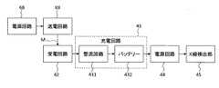
無線X線検出器4の受電装置41は、送電装置60からの振動磁場Mを受けて電力を発生する。受電装置41は、受電回路42、充電回路43及び電源回路44を有する。受電回路42には、振動磁場Mを受けて電力を発生する受信コイル(共振器)が設けられている。受信コイルは、実質的に送信コイルと等しい共振周波数を有する。「実質的に等しい」とは、後述の磁気共鳴を用いて送電・受電を実現するにあたり、支障が無い程度の誤差を許容することを意味する。受信コイルについては、後述の[送電・受電の方法]において説明する。充電回路43は、受電回路42により生成された電力を蓄電する。図3に示すように、充電回路43には、整流回路431とバッテリー432が設けられている。整流回路431は、受電回路42により生成された交流電力を直流電力に変換する。バッテリー432は、この直流電力を蓄電する。電源回路44は、バッテリー432に蓄電された電力をX線検出部45、信号処理部46、制御部47及び送受信部49に供給する。なお、充電監視部48に対してもこの電力を供給するように構成されていてもよい。 The
X線検出部45はFPDである。信号処理部46は、X線検出部45により生成された電気信号に対して所定の処理を施す。この処理やそのパラメータは、メイン制御部70から送受信部77、49を介して入力される制御信号に基づいて決定される。制御部47は、電源回路44、信号処理部46、送受信部49等を制御する。充電監視部48は、バッテリー432の充電レベルを検知する。充電レベルは、たとえばバッテリー432の現在の蓄電量とバッテリー432の最大蓄電量(既定値)との比である。充電監視部48は、バッテリー432の現在の蓄電量を検知するよう構成されていてもよいし、充電時間や振動磁場Mの強度などに基づいて現在の蓄電量を推定するよう構成されていてもよい。後者の場合、装置本体側に充電監視部を設けることができる。送受信部49は、送受信部77との間で無線通信を行う。この無線通信の方式は任意である。 The
[送電・受電の方法]
送電装置60と受電装置41を用いた送電・受電の方法について説明する。[Method of power transmission / reception]
A power transmission / reception method using the power transmission device 60 and the
この実施形態では、実質的に等しい共振周波数を有する送信コイルと受信コイルを使用し、磁気共鳴による非接触の電力供給を行う。磁気共鳴を利用した給電方法は、電磁誘導や電波を利用した他の方法と比較し、遠距離(3〜4m程度)かつ高出力(数W〜数kW程度)での非接触給電を実現できるというメリットがある。これは、医用画像診断装置の無線デバイスにとって特に有効である。また、磁気共鳴による電力供給には、両コイルの軸が多少ずれていても送電・受電が可能である、両コイルの間に障害物が存在しても送電・受電が可能である、共振周波数を違えることにより複数のデバイスへの選択的な給電が可能である、といった利点もある。 In this embodiment, a transmitter coil and a receiver coil having substantially the same resonance frequency are used, and non-contact power supply is performed by magnetic resonance. The power feeding method using magnetic resonance can realize non-contact power feeding at a long distance (about 3 to 4 m) and high output (several W to several kW) as compared with other methods using electromagnetic induction and radio waves. There is a merit. This is particularly effective for the wireless device of the medical image diagnostic apparatus. In addition, power supply by magnetic resonance allows power transmission / reception even if the axes of both coils are slightly deviated from each other. Resonance frequency allows transmission / reception even if there is an obstacle between the coils. There is also an advantage that selective power supply to a plurality of devices is possible by making the difference.
このような送電・受電方法を実現するための送電装置60と受電装置41の回路構成の概要を図4に示す。 FIG. 4 shows an outline of the circuit configuration of the power transmission device 60 and the
送電装置60の電源回路68は、交流電源681と交流抵抗682を有する。交流電源681は、外部の交流電源からの電力を送電装置60に入力する。交流抵抗682は所定のインピーダンスを有する。送電回路69は、送信コイル691と、コンデンサ692と、抵抗693とを有する共振回路(共振器)である。送信コイル691は、交流電力の供給を受けて振動磁場を発生する。 The
受電装置41の受電回路42は、受信コイル241と、コンデンサ422と、抵抗423と、負荷424とを有する共振回路である。受電回路42(受信コイル241)は、実質的に送電回路69(送信コイル691)と等しい共鳴周波数を有する。つまり、送信側の共振回路と受信側の共振回路は、実質的に等しい共鳴周波数を有する。このような構成とすることにより、適当な位置関係に配置された送電装置60と受電装置41との間において、磁気共鳴を用いた非接触の電力供給が可能となる。 The
[使用形態]
以上のような構成を有するX線診断装置の使用形態について説明する。[Usage form]
A usage pattern of the X-ray diagnostic apparatus having the above configuration will be described.
(第1の使用形態)
送電装置60、特に送電装置62は、振動磁場を発生しているものとする。ユーザーが天板21に無線X線検出器4を載置すると、受電回路42は、この振動磁場を受けて電力を発生する。この電力は整流回路431に送られて直流電力に変換され、バッテリー432に蓄電される。十分に充電されたら、ユーザーは所定の操作を行って送電装置62による磁場発生を停止させる。(First usage pattern)
It is assumed that the power transmission device 60, particularly the
ユーザーが所定の操作を行ってX線撮影の開始を指示すると、メイン制御部70は、送受信部77を介して無線X線検出器4に制御信号を送る。無線X線検出器4の制御部47は、電源回路44を制御し、バッテリー432に蓄電された電力をX線検出部45等に供給させる。X線管14からX線が出力されると、X線検出部45は、被検体を透過したX線を検出し、電気信号を出力する。信号処理部46は、この電気信号に対して所定の処理を施す。制御部47は、信号処理部46から出力されるデータを、送受信部49、77を介してメイン制御部70に送る。メイン制御部70は、このデータを画像処理部73に送る。画像処理部73は、このデータに対して所定の画像処理を施し、表示部75に画像を表示させたり、画像記憶部74に画像データを記憶させたりする。 When the user performs a predetermined operation to instruct the start of X-ray imaging, the
なお、無線X線検出器4が給電可能な位置に配置されているか否かを報知する機能を無線X線検出器4に設けることができる。その一例として、受電回路42により発生された電力で点灯する光源(LED等)を設けることができる。また、給電レベル(磁場から電力への変換効率)に応じた個数が点灯される複数の光源を設けたり、給電レベルに応じて発光輝度が変わる光源を設けるなどして、給電レベルを報知するようにしてもよい。給電レベルは、たとえば充電監視部48により検出される。 The wireless X-ray detector 4 can be provided with a function for notifying whether or not the wireless X-ray detector 4 is arranged at a position where power can be supplied. As an example thereof, a light source (LED or the like) that is lit with power generated by the
また、充電レベルを呈示する機能を設けてもよい。充電レベルは充電監視部48により検出される。充電レベルは、無線X線検出器4や装置本体に設けられた呈示部に呈示される。無線X線検出器4に設けられた呈示部としては、光源や表示デバイス(LCD等)がある。また、装置本体に設けられた呈示部としては、撮影条件入力部13(のLCD等)や、表示部75などがある。なお、バッテリー432の充電レベルと残量は同じ概念である。 Moreover, you may provide the function to show a charge level. The charge level is detected by the
(第2の使用形態)
この使用形態では、実際のX線撮影が行われていないときにのみ給電を行うための制御について説明する。特に、この使用形態では、X線撮影の開始トリガーに対応して給電を停止する制御について説明する。この開始トリガーとしては、(1)装置本体への患者情報の入力、(2)検査の開始を指示するための操作の実行、(3)デバイスの所定位置への配置、などがある。この使用形態に係るX線診断装置は、X線撮影の開始トリガーを検知する第1検知部を有する。(Second usage pattern)
In this usage mode, control for supplying power only when actual X-ray imaging is not performed will be described. In particular, in this usage pattern, control for stopping power feeding in response to a start trigger for X-ray imaging will be described. Examples of the start trigger include (1) input of patient information to the apparatus main body, (2) execution of an operation for instructing start of an examination, and (3) arrangement of a device at a predetermined position. The X-ray diagnostic apparatus according to this usage pattern includes a first detection unit that detects an X-ray imaging start trigger.
(1)患者情報の入力に基づく制御について説明する。患者情報の入力は、図示しないコンソールを用いて行われる。コンソールは、患者情報の入力の開始から終了までの間の任意のタイミングで、メイン制御部70に信号を送る。この信号を受けたメイン制御部70は、送電制御部76を介して送電装置62の動作を停止させる。それにより、無線X線検出器4への給電が停止される。なお、充電レベルが閾値以下である場合に、その旨を報知するように構成することが可能である。この場合における第1検知部は、コンソール又はメイン制御部70である。 (1) Control based on patient information input will be described. The patient information is input using a console (not shown). The console sends a signal to the
(2)検査の開始の指示に基づく制御について説明する。検査の開始の指示は、撮影条件入力部13やコンソール、或いは図示しない専用の撮影開始スイッチを操作することによりなされる。撮影開始の操作がなされると、その操作信号がメイン制御部70に入力される。この操作信号を受けたメイン制御部70は、上記と同じ要領で給電を停止させる。この場合における第1検知部は、メイン制御部70である。 (2) Control based on an instruction to start inspection will be described. An instruction to start the inspection is made by operating the imaging
(3)デバイスが所定位置に配置されたことに基づく制御について説明する。この例では、上記構成に加え、当該所定位置のそれぞれにセンサやスイッチ等が設けられる。具体的には、マイクロスイッチなどが設けられる。また、当該所定位置としては、FPDホルダー51、52や、天板21などがある。 (3) The control based on the device being placed at a predetermined position will be described. In this example, in addition to the above configuration, a sensor, a switch, or the like is provided at each of the predetermined positions. Specifically, a micro switch or the like is provided. Further, as the predetermined position, there are
無線X線検出器4が所定位置に配置されると、上記センサ等がこれを検知し、メイン制御部70に検知信号を送る。この検知信号を受けたメイン制御部70は、上記と同じ要領で給電を停止させる。この場合における第1検知部は、上記センサ等である。 When the wireless X-ray detector 4 is disposed at a predetermined position, the sensor or the like detects this and sends a detection signal to the
(第3の使用形態)
この使用形態では、実際のX線撮影が行われていないときにのみ給電を行うための制御の他の例について説明する。具体的には、X線撮影の終了トリガーに対応して給電を開始する制御について説明する。この終了トリガーとしては、(1)検査に関する処理の終了、(2)検査の終了を指示するための操作の実行、(3)装置本体又はデバイスの電源オフ操作の実行、(4)装置本体及びデバイスに対する操作が所定時間以上行われないこと、などがある。この使用形態に係るX線診断装置は、X線撮影の終了トリガーを検知する第2検知部を有する。(Third usage pattern)
In this usage pattern, another example of control for supplying power only when actual X-ray imaging is not performed will be described. Specifically, control for starting power feeding in response to an X-ray imaging end trigger will be described. As the end trigger, (1) the end of the process related to the inspection, (2) the execution of the operation for instructing the end of the inspection, (3) the execution of the power-off operation of the apparatus main body or the device, (4) the apparatus main body and For example, the device may not be operated for a predetermined time. The X-ray diagnostic apparatus according to this usage pattern includes a second detection unit that detects an X-ray imaging end trigger.
(1)検査に関する処理の終了に基づく制御について説明する。検査に関する処理としては、たとえば、X線管14によるX線の照射、X線検出器45によるX線の検出、画像処理部73による画像処理などがある。X線管14や画像処理部73の制御はメイン制御部70が司っている。メイン制御部70は、X線管14等の制御を終了したら、送電制御部76を介して送電装置62の動作を開始させる。それにより、無線X線検出器4への給電が開始される。この場合の第2検知部は、メイン制御部70である。 (1) The control based on the end of the process related to the inspection will be described. As processing related to the inspection, for example, there are X-ray irradiation by the
(2)検査の終了を指示するための操作に基づく制御について説明する。当該指示は、撮影条件入力部13やコンソール、或いは図示しない専用の撮影終了スイッチを操作することによりなされる。撮影終了の操作がなされると、その操作信号がメイン制御部70に入力される。この操作信号を受けたメイン制御部70は、上記と同じ要領で給電を開始させる。この場合における第2検知部は、メイン制御部70である。 (2) The control based on the operation for instructing the end of the inspection will be described. This instruction is made by operating the photographing
(3)電源オフ操作に基づく制御について説明する。装置本体の電源オフ操作は、撮影条件入力部13、コンソール、図示しない専用の電源スイッチを用いてなされる。無線X線検出器4の電源オフ操作は、図示しない電源スイッチを用いてなされる。装置本体の電源オフ操作がなされると、その操作信号がメイン制御部70に送られる。この操作信号を受けたメイン制御部70は、装置各部への電源供給を終了させる処理と、上記要領で給電を開始させる処理とを実行する。この場合における第2検知部は、メイン制御部70である。 (3) Control based on the power-off operation will be described. The power-off operation of the apparatus main body is performed using the photographing
一方、無線X線検出器4の電源オフ操作がなされると、その操作信号は制御部47に送られる。この操作信号を受けた制御部47は、送受信部49、77を介してメイン制御部70に信号を送る。この信号を受けたメイン制御部70は、上記と同じ要領で給電を開始させる。このとき、装置各部への電源供給を終了させる処理も行うようにしてもよい。この場合における第2検知部は、制御部70又はメイン制御部70である。 On the other hand, when the power-off operation of the wireless X-ray detector 4 is performed, the operation signal is sent to the
(4)操作が所定時間以上行われないことに基づく制御について説明する。メイン制御部70は、図示しないタイマー(計時部)を有する。このタイマーの機能は、たとえばマイクロプロセッサが担う。メイン制御部70は、操作がなされる度に、つまり装置各部からの操作信号が入力される度に、タイマーをリセットする。タイマーによる計時時間が所定時間に達すると、メイン制御部70は、上記と同じ要領で給電を開始させる。この場合における第2検知部は、メイン制御部70である。 (4) Control based on the fact that the operation is not performed for a predetermined time or more will be described. The
(第4の使用形態)
この使用形態では、充電レベルに応じて給電を制御する場合について説明する。充電レベルは、前述のように充電監視部48(第3検知部)により検出される。充電監視部48は、所定の時間間隔で送受信部49、77を介して、充電レベルの検出結果をメイン制御部70に送る。メイン制御部70は、この検知結果が所定の第1レベル以下であるか判断する。検知結果が第1レベル以下である場合、メイン制御部70は、上記と同じ要領で給電を開始させる。(Fourth usage pattern)
In this usage pattern, a case where power feeding is controlled according to the charge level will be described. The charge level is detected by the charge monitoring unit 48 (third detection unit) as described above. The
充電レベルが第1レベル以下であるかの判断を充電監視部48が行うようにしてもよい。この場合、充電監視部48は、充電レベルが第1レベル以下である場合にのみ、メイン制御部70に信号を送るように構成できる。 The
逆に、充電レベルの検出結果が所定の第2レベル(たとえば最大蓄電量)以上である場合に、給電を停止させるように構成することも可能である。この判断は、メイン制御部70又は制御部47により実行される。また、撮影の残り時間等の条件が推定できる場合などには、この条件に基づいて第2レベルを算出し、この算出された第2レベルを判断基準とすることができる。 Conversely, it is also possible to configure the power supply to stop when the detection result of the charge level is equal to or higher than a predetermined second level (for example, the maximum charged amount). This determination is performed by the
(第5の使用形態)
この使用形態では、送電装置60と受電装置41(無線X線検出器4)との距離に応じて給電を制御する場合について説明する。この使用形態に係るX線診断装置は、当該距離が所定距離以下になったか否か判定する判定部を有する。判定部は、(1)当該距離を常時監視し、距離の検出結果と閾値とを比較するように構成されていてもよいし、(2)送電装置60に対して所定距離以下の領域に受電装置41が配置されたことを検知するように構成されていてもよい。(Fifth usage pattern)
In this usage pattern, a case where power feeding is controlled according to the distance between the power transmitting device 60 and the power receiving device 41 (wireless X-ray detector 4) will be described. The X-ray diagnostic apparatus according to this usage pattern includes a determination unit that determines whether or not the distance is equal to or less than a predetermined distance. The determination unit may be configured to (1) constantly monitor the distance and compare the detection result of the distance with a threshold value, or (2) receive power in an area below a predetermined distance with respect to the power transmission device 60. You may be comprised so that it may detect that the
(1)における常時監視の機能は、たとえば、検査室内を撮影するテレビカメラと、メイン制御部70とにより実現される。この場合におけるメイン制御部70は、テレビカメラによる撮影画像を解析して無線X線検出器4の位置を検出し、この位置と、既定の送電装置60の位置との間の距離を求める。更に、(1)における比較処理は、メイン制御部70が実行する。当該距離が所定距離以下である場合、メイン制御部70は、上記と同じ要領で給電を開始させる。この場合における判定部は、メイン制御部70とテレビカメラにより構成される。なお、常時監視の手段及び比較処理を行う手段は上記の構成には限定されず、その機能を実現可能な任意の技術であってよい。 The constant monitoring function in (1) is realized by, for example, a television camera that captures an image of the examination room and the
(2)における検知処理についても、テレビカメラとメイン制御部70により実現できる。具体的には、送電装置60に対して所定距離以下の領域のみを撮影するようにテレビカメラを配置・設定すればよい。メイン制御部70は、テレビカメラによる撮影画像を解析し、当該撮影領域内に無線X線検出器4が描画されているか判定する。無線X線検出器4が描画されていると判定された場合、メイン制御部70は、上記と同じ要領で給電を開始させる。この場合における判定部は、メイン制御部70とテレビカメラにより構成される。上記検知処理を行う手段は上記の構成には限定されず、その機能を実現可能な任意の技術であってよい。たとえば、所定強度の信号(電波等)を発信する発信部を無線X線検出器4に設けるとともに、この信号を受信する受信部を送電装置60に設ける。そして、受信部により受信される信号の強度が所定レベル以上になったことに対応して給電を開始するよう構成できる。逆に、受信部により受信される信号の強度が所定レベル未満になったことに対応して給電を停止するように構成することもできる。 The detection process in (2) can also be realized by the television camera and the
[効果]
この実施形態に係るX線診断装置の効果について説明する。[effect]
The effect of the X-ray diagnostic apparatus according to this embodiment will be described.
実施形態に係るX線診断装置は、被検体内からの信号を受信して被検体内の画像(生体情報)を取得する医用画像診断装置である。このX線診断装置は、装置本体と、送電装置60と、受電装置41を含む無線X線検出器4(デバイス)とを有する。送電装置60には、外部から電力を受けて振動磁場を発生する送信コイル691(送電回路69)を有する。受電装置41は、実質的に送信コイル691と等しい共振周波数を有し、送信コイル691により発生された振動磁場を受けて電力を発生する受信コイル241(受電回路42)を含む。無線X線検出器4は、受信コイル241により発生された電力により動作する。 An X-ray diagnostic apparatus according to an embodiment is a medical image diagnostic apparatus that receives a signal from a subject and acquires an image (biological information) in the subject. This X-ray diagnostic apparatus includes an apparatus main body, a power transmission apparatus 60, and a wireless X-ray detector 4 (device) including a
このようなX線診断装置によれば、無線X線検出器4に対する電力供給を、磁気共鳴を用いた給電方法によって行うことができるので、装置本体と連係して動作するデバイスへの電力供給を好適に行うことが可能である。具体的には、たとえば、遠距離かつ高出力(数W〜数kW程度)で給電を行うことができる、両コイルの軸が多少ずれていても給電が可能である、コイル間に障害物があっても給電が可能であるといった効果が得られる。また、従来の給電方法のように、専用の充電器に接続又は近接させる必要もない。よって、バッテリー432の充電をし忘れるおそれが低減される。また、専用の充電器に無線X線検出器4を接続したり近接させたりする手間がなくなり、操作性が向上する。 According to such an X-ray diagnostic apparatus, power can be supplied to the wireless X-ray detector 4 by a power feeding method using magnetic resonance, so that power can be supplied to a device that operates in conjunction with the apparatus main body. It can be suitably performed. Specifically, for example, power can be supplied at a long distance and high output (several W to several kW). Power can be supplied even if the axes of both coils are slightly shifted. There is an obstacle between the coils. Even if it exists, the effect that electric power feeding is possible is acquired. Further, unlike the conventional power supply method, it is not necessary to connect or approach a dedicated charger. Therefore, the risk of forgetting to charge the
また、この実施形態において、送電装置60は、装置本体、検査室の床・天井・壁などに設けられている。なお、送電装置60は、検査時に無線X線検出器4が設置される位置の近傍に設けられる。この「近傍」とは、少なくとも磁気共鳴による給電が可能な距離である。このように構成することにより、バッテリー432の充電をし忘れるおそれを低減することが可能である。 In this embodiment, the power transmission device 60 is provided on the device main body, the floor / ceiling / wall of the examination room, and the like. The power transmission device 60 is provided near the position where the wireless X-ray detector 4 is installed at the time of inspection. This “neighborhood” is a distance at which power can be supplied by at least magnetic resonance. With this configuration, it is possible to reduce the risk of forgetting to charge the
また、この実施形態に係る無線X線検出器4(デバイス)は、受電回路42により発生された電力を蓄電するバッテリー432を有し、このバッテリー432に蓄電された電力によって動作(X線の検出、画像処理等)する。このようにデバイスにバッテリーを搭載することで、送電装置60を常時動作させる必要がなくなる。 Further, the wireless X-ray detector 4 (device) according to this embodiment includes a
また、この実施形態に係るX線診断装置は、バッテリー432の残量を呈示する呈示部を有する。それにより、ユーザーはバッテリー432の残量を把握することができ、必要に応じて充電を開始したり終了したりすることができる。 In addition, the X-ray diagnostic apparatus according to this embodiment includes a presentation unit that presents the remaining amount of the
また、この実施形態のメイン制御部70は、装置本体及びデバイスによる検査(X線撮影)が行われていないときにのみ給電を行わせる。検査を行っているときに給電を行うと、送電装置60が発生した振動磁場Mが検査に悪影響を与える可能性がある。この悪影響としては、装置本体やデバイスの誤動作などが考えられる。なお、このように動作するメイン制御部70は「制御部」に含まれる。 In addition, the
また、この実施形態のX線診断装置は、検査の開始トリガーを検知する第1検知部を有し、この開始トリガーが検知されたことに対応して送電装置60への電力の給電を停止する。それにより、無線X線検出器4への給電が停止される。このような構成により、検査が行われていないときにのみ給電を行うための制御が実現される。なお、開始トリガーは、検査の開始やその準備に相当するタイミングを示す。開始トリガーには、装置本体への患者情報の入力、検査の開始を指示するための操作の実行、及び、デバイスの所定位置への配置のうちの少なくとも1つが含まれる。また、第1検知部は、メイン制御部70とともに「制御部」に含まれる。 In addition, the X-ray diagnostic apparatus according to this embodiment includes a first detection unit that detects a start trigger of an examination, and stops power supply to the power transmission device 60 in response to detection of the start trigger. . Thereby, the power supply to the wireless X-ray detector 4 is stopped. With such a configuration, control for supplying power only when inspection is not performed is realized. The start trigger indicates the timing corresponding to the start of the inspection and its preparation. The start trigger includes at least one of inputting patient information to the apparatus main body, performing an operation for instructing the start of the examination, and disposing the device at a predetermined position. The first detection unit is included in the “control unit” together with the
また、この実施形態のX線診断装置は、検査の終了トリガーを検知する第2検知部を有し、この終了トリガーが検知されたことに対応して送電装置60への電力の供給を開始する。それにより、無線X線検出器4への給電が開始される。このような構成により、検査が行われていないときにのみ給電を行うための制御が実現される。なお、終了トリガーは、検査の終了やその準備、或いは検査終了後の処理に相当するタイミングを示す。終了トリガーには、検査に関する処理の終了、検査の終了を指示するための操作の実行、装置本体又はデバイスの電源オフ操作の実行、並びに、装置本体及びデバイスに対する操作が所定時間以上行われないことのうちの少なくとも1つが含まれる。また、第2検知部は、メイン制御部70とともに「制御部」に含まれる。 In addition, the X-ray diagnostic apparatus of this embodiment has a second detection unit that detects the end trigger of the examination, and starts supplying power to the power transmission apparatus 60 in response to the detection of the end trigger. . Thereby, the power supply to the wireless X-ray detector 4 is started. With such a configuration, control for supplying power only when inspection is not performed is realized. The end trigger indicates the timing corresponding to the end of inspection, its preparation, or processing after the end of inspection. In the end trigger, the end of the processing related to the inspection, the execution of the operation for instructing the end of the inspection, the execution of the power-off operation of the apparatus main body or the device, and the operation of the apparatus main body and the device are not performed for a predetermined time or more. At least one of them. The second detection unit is included in the “control unit” together with the
また、この実施形態のX線診断装置は、バッテリー432の充電レベルを検知する第3検知部と、この充電レベルの検知結果に基づいて送電装置60への電力の供給を制御するメイン制御部70とを有する。この制御は、充電レベル(バッテリー残量)の低下に対応する給電の開始と、充電レベルが十分な状態になったことに対応する給電の停止との少なくとも一方を含む。前者によれば、バッテリー432の充電レベルが大きく低下して検査を中止するといった事態を防止することができる。また、バッテリー432を充電するタイミングを気にする必要がなくなる。一方、後者によれば、バッテリー432の過充電の防止や、節電といった効果が得られる。なお、このように動作するメイン制御部70は「制御部」の一例に相当する。 In addition, the X-ray diagnostic apparatus of this embodiment includes a third detection unit that detects the charge level of the
また、この実施形態のX線診断装置は、送電装置60(送信コイル)と無線X線検出器4との距離が所定距離以下であるか判定する判定部と、この距離の判定結果に基づいて送電装置60への電力の供給を制御するメイン制御部70とを有する。この制御は、当該距離が所定距離以下である場合に給電を行う制御と、当該距離が所定距離を超える場合に給電を行わない制御との少なくとも一方を含む。前者には、当該距離をモニターしている場合において当該距離が所定距離以下に移行したことに対応する給電の開始と、任意のタイミングで検出された当該距離が所定距離以下である場合に給電を開始する制御との少なくとも一方が含まれる。一方、後者には、当該距離をモニターしている場合において当該距離が所定距離を超えたことに対応する給電の停止と、任意のタイミングで検出された当該距離が所定距離を超えている場合に給電を停止する制御との少なくとも一方が含まれる。このような制御によれば、無線X線検出器4の配置や移動に応じて自動的に給電を開始したり停止したりすることができるので、利便性が高まる。 Moreover, the X-ray diagnostic apparatus of this embodiment is based on the determination part which determines whether the distance of the power transmission apparatus 60 (transmission coil) and the radio | wireless X-ray detector 4 is below a predetermined distance, and the determination result of this distance. And a
なお、この実施形態では無線X線検出器4に対する給電について説明したが、給電対象はこれに限定されるものではない。たとえば、支持機構12を伸縮・移動させるアクチュエーターや、表示デバイスや、X線絞り15の絞り羽根を駆動するアクチュエーターや、臥位用撮影台2及び/又は立位用撮影台3のアクチュエーターに対して給電を行うように構成することが可能である。 In addition, although this embodiment demonstrated the electric power feeding with respect to the radio | wireless X-ray detector 4, the electric power feeding object is not limited to this. For example, with respect to an actuator for expanding and contracting the
また、この実施形態に係るX線診断装置は、それぞれ異なる位置に設置された複数の送電装置61〜66を備えている。このように構成することにより、検査室内の様々な位置に配置された無線X線検出器4に給電することができる。 In addition, the X-ray diagnostic apparatus according to this embodiment includes a plurality of
更に、或る位置に配置された無線X線検出器4に対し、送電装置61〜66のうちの2つ以上によって同時に給電を行うことも可能である。たとえば、FPDホルダー51に装着された状態の無線X線検出器4に対し、送電装置63と送電装置65によって同時に給電することができる。また、FPDホルダー52の近傍に無線X線検出器4を水平に配置させることで、つまり各受電装置61、66の送信コイル691の軸に対して、受信コイル421の軸を略平行に配置することで、送電装置61と送電装置66により同時に無線X線検出器4に対して給電することができる。このような給電方法によれば、受電装置41は、送電装置61〜66のうちの2つ以上により発生された振動磁場を同時に受けて電力を発生することができるので、1つの送電装置のみを用いる場合よりも迅速に給電を行うことが可能である(つまり急速充電が可能である。)なお、メイン制御部70は、無線X線検出器4の配置に応じて、送電装置61〜66のうちから幾つか(たとえば当該配置位置に比較的近くに設置されたもの)を選択し、選択された送電装置のみを動作させることができる。 Furthermore, it is also possible to simultaneously feed power to the wireless X-ray detector 4 arranged at a certain position by two or more of the
[変形例]
この発明の実施形態は上記のものには限定されない。以下、各種の変形例について説明する。なお、上記の実施形態における各種構成や、下記の各種変形例を適宜に組み合わせることが可能である。[Modification]
The embodiment of the present invention is not limited to the above. Hereinafter, various modifications will be described. In addition, it is possible to combine suitably the various structures in said embodiment and the following various modifications.
(変形例1)
変形例に係る医用画像診断装置(X線診断装置)を図5に示す。変形例に係るX線診断装置の装置本体は、上記実施形態と同様に構成されている。なお、図5には、図1に示した装置本体の構成の一部のみが記載されている。また、変形例に係るデバイスとしては、2つの無線X線検出器4A、4Bが用いられる。各無線X線検出器4は、上記実施形態の無線X線検出器4と同様の構成を有する。特に、無線X線検出器4Aは受電装置41Aを有し、無線X線検出器4Bは受電装置41Bを有する。(Modification 1)
FIG. 5 shows a medical image diagnostic apparatus (X-ray diagnostic apparatus) according to a modification. The apparatus main body of the X-ray diagnostic apparatus according to the modification is configured in the same manner as in the above embodiment. 5 shows only a part of the configuration of the apparatus main body shown in FIG. As a device according to the modification, two
ユーザーは、給電に適した任意の位置に2つの無線X線検出器4A、4Bを配置させる。図5では、天板2上かつ送電装置62の下方位置に2つの無線X線検出器4A、4Bが配置される。この状態で送電装置62に電力を供給すると、送電装置62により発生された振動磁場によって双方の受電装置41A、41Bが電力を発生し、図示しない双方のバッテリーに蓄電される。 The user places the two
このような手法は、磁気共鳴を利用した給電方法の特性、特に遠距離での給電が可能であること、そして送電側と給電側とのコイルの軸が多少ずれていても給電が可能であることにより実現されるものである。なお、1つの送電装置60により同時に給電される無線X線検出器4の個数は2つには限定されない。 Such a method can supply power even when the power transmission side and the power supply side are slightly deviated from the characteristics of the power supply method using magnetic resonance, particularly power supply at a long distance. Is realized. The number of wireless X-ray detectors 4 that are simultaneously fed by one power transmission device 60 is not limited to two.
このように、変形例に係るX線診断装置は、2つ以上の無線X線検出器(デバイス)を備え、これらデバイスに含まれる2つ以上の受電装置(受信コイル)は、1つの送電装置(送信コイル)により発生された振動磁場を受けて電力を発生するものである。それにより、複数のデバイスが設けられた医用画像診断装置において、2つ以上のデバイスに対して同時に給電を行えるという効果が得られる。 As described above, the X-ray diagnostic apparatus according to the modification includes two or more wireless X-ray detectors (devices), and two or more power receiving apparatuses (receiving coils) included in these devices are one power transmitting apparatus. In response to the oscillating magnetic field generated by the (transmission coil), electric power is generated. Thereby, in the medical image diagnostic apparatus provided with a plurality of devices, there is an effect that power can be supplied to two or more devices simultaneously.
(変形例2)
上記実施形態では、バッテリーを備えたデバイスに対して磁気共鳴を用いて給電する構成、つまりデバイスのバッテリーを非接触で充電する構成について説明した。この変形例では、デバイスがバッテリーを具備しない場合について説明する。なお、この場合においては、デバイスの動作中に常に給電を行う必要がある。(Modification 2)
In the above-described embodiment, the configuration in which power is supplied to the device including the battery using magnetic resonance, that is, the configuration in which the battery of the device is charged in a non-contact manner has been described. In this modification, a case where the device does not include a battery will be described. In this case, it is necessary to always supply power during the operation of the device.
デバイスがバッテリーを具備しない場合においても、装置本体の構成は上記実施形態と同様である(たとえば図1、図2参照)。デバイスが無線X線検出器である場合、図3に示す構成からバッテリー432を除いた構成を適用できる。つまり、受電回路42により生成された交流電力を整流回路431で直流電力に変換し、この直流電力を電源回路44がX線検出部45等に供給する構成を適用することができる。 Even when the device does not include a battery, the configuration of the apparatus main body is the same as that of the above-described embodiment (see, for example, FIGS. 1 and 2). When the device is a wireless X-ray detector, a configuration in which the
この変形例では、少なくとも検査中(X線撮影中)に、無線X線検出器4への電力供給を行う。たとえば、上記実施形態の「開始トリガー」を受けたメイン制御部70は、送電装置60への電力供給を開始する。それにより、送電装置60から無線X線検出器4への給電が開始される。また、上記実施形態「終了トリガー」を受けたメイン制御部70は、送電装置60への電力供給を停止する。それにより、送電装置60から無線X線検出器4への給電が停止される。 In this modification, power is supplied to the wireless X-ray detector 4 at least during inspection (during X-ray imaging). For example, the
この変形例によれば、バッテリーを有しないデバイスに対して好適に電力供給を行うことができる。 According to this modification, it is possible to suitably supply power to a device that does not have a battery.
なお、この変形例において、装置本体等への磁場の悪影響を回避するために、検査時に無線X線検出器4が配置される位置のごく近傍にのみ送電装置60を設置することができる。たとえば、図1に示す送電装置61〜66のうち、天板21近傍に配置可能な送電装置62と、それぞれFPDホルダー51、52の近傍の送電装置63、64のみを設置することが可能である。 In this modification, in order to avoid the adverse effect of the magnetic field on the apparatus main body and the like, the power transmission apparatus 60 can be installed only in the vicinity of the position where the wireless X-ray detector 4 is arranged at the time of inspection. For example, among the
(変形例3)
X線診断装置以外の医用画像診断装置への上記実施形態及び変形例の適用について説明する。このような医用画像診断装置としては、前述のようにMRI装置や超音波診断装置がある。(Modification 3)
The application of the above-described embodiment and modifications to medical image diagnostic apparatuses other than X-ray diagnostic apparatuses will be described. As such a medical image diagnostic apparatus, there are an MRI apparatus and an ultrasonic diagnostic apparatus as described above.
MRI装置におけるデバイスは、たとえば高周波コイルユニットである。たとえば特開2010−207464号公報に記載のように、高周波コイルユニットは、検査時に被検体の所定部位(頭部など)に装着される。上記の実施形態や変形例で説明した給電に関する構成を、高周波コイルユニットに適用することが可能である。 A device in the MRI apparatus is, for example, a high-frequency coil unit. For example, as described in Japanese Patent Application Laid-Open No. 2010-207464, the high frequency coil unit is attached to a predetermined part (such as the head) of the subject at the time of examination. The configuration related to the power supply described in the above embodiments and modifications can be applied to the high-frequency coil unit.
超音波診断装置におけるデバイスは、たとえば超音波プローブである。超音波プローブは、被検体に対して超音波を照射するとともに、その体内からの反射波を受信する。なお、超音波プローブには有線のものと無線のものがあるが(たとえば特開2008−000406号公報を参照)、上記の実施形態や変形例で説明した給電に関する構成は、そのどちらに対しても適用可能である。 The device in the ultrasonic diagnostic apparatus is, for example, an ultrasonic probe. The ultrasonic probe irradiates a subject with ultrasonic waves and receives a reflected wave from the body. Note that there are wired and wireless ultrasonic probes (see, for example, Japanese Patent Application Laid-Open No. 2008-000406). Is also applicable.
なお、上記の実施形態や変形例で説明した給電に関する構成を、これら以外の医用画像診断装置やデバイスに対して適用することが可能である。 Note that the configuration relating to the power supply described in the above-described embodiments and modifications can be applied to other medical image diagnostic apparatuses and devices.
この発明の実施形態を説明したが、上記の実施形態は例として提示したものであり、発明の範囲を限定することを意図していない。これら新規な実施形態は、その他の様々な形態で実施されることが可能であり、発明の要旨を逸脱しない範囲で、種々の省略、置き換え、変更を行うことができる。これら実施形態やその変形は、発明の範囲や要旨に含まれるとともに、特許請求の範囲に記載された発明とその均等の範囲に含まれる。 Although the embodiment of the present invention has been described, the above-described embodiment has been presented as an example, and is not intended to limit the scope of the invention. These novel embodiments can be implemented in various other forms, and various omissions, replacements, and changes can be made without departing from the scope of the invention. These embodiments and modifications thereof are included in the scope and gist of the invention, and are included in the invention described in the claims and the equivalents thereof.
1 天井走行式X線照射装置
14 X線管
15 X線絞り
2 臥位用撮影台
3 立位用撮影台
4、4A、4B 無線X線検出器
41、41A、41B 受電装置
42 受電回路
43 充電回路
431 整流回路
432 バッテリー
44 電源回路
45 X線検出部
46 信号処理部
47 制御部
48 充電監視部
49 送受信部
51、52 FPDホルダー
60、61、62、63、64、65、66 送電装置
67 電源制御部
68 電源回路
69 送電回路
70 メイン制御部
76 送電制御部
77 送受信部
M 振動磁場yDESCRIPTION OF SYMBOLS 1 Ceiling-running
Claims (15)
Translated fromJapanese装置本体と、
外部から電力を受けて振動磁場を発生する送信コイルと、
実質的に前記送信コイルと等しい共振周波数を有し、前記送信コイルにより発生された振動磁場を受けて電力を発生する受信コイルを含み、前記受信コイルにより発生された電力により動作するデバイスと、
を備える医用画像診断装置。A medical image diagnostic apparatus that receives a signal from within a subject and acquires biological information of the subject,
The device body;
A transmitting coil that receives electric power from the outside and generates an oscillating magnetic field;
A device that has a resonance frequency substantially equal to that of the transmission coil, includes a reception coil that receives an oscillating magnetic field generated by the transmission coil and generates electric power, and operates by the electric power generated by the reception coil;
A medical image diagnostic apparatus comprising:
前記充電レベルの検知結果に基づいて前記送信コイルへの電力の供給を制御する制御部と、
を備えることを特徴とする請求項4〜請求項10のいずれか一項に記載の医用画像診断装置。A third detector for detecting a charge level of the battery;
A control unit for controlling the supply of power to the transmission coil based on the detection result of the charge level;
The medical image diagnostic apparatus according to any one of claims 4 to 10, further comprising:
前記距離の判定結果に基づいて前記送信コイルへの電力の供給を制御する制御部と、
を備えることを特徴とする請求項1〜請求項11のいずれか一項に記載の医用画像診断装置。A determination unit for determining whether a distance between the transmission coil and the device is a predetermined distance or less;
A control unit for controlling the supply of power to the transmission coil based on the determination result of the distance;
The medical image diagnostic apparatus according to claim 1, further comprising:
前記2つ以上のデバイスに含まれる2つ以上の前記受信コイルは、1つの前記送信コイルにより発生された振動磁場を受けて電力を発生する、
ことを特徴とする請求項1〜請求項13のいずれか一項に記載の医用画像診断装置。Comprising two or more of the devices,
Two or more of the receiving coils included in the two or more devices receive an oscillating magnetic field generated by one of the transmitting coils and generate electric power;
The medical image diagnostic apparatus according to claim 1, wherein the medical image diagnostic apparatus is a medical image diagnostic apparatus.
Priority Applications (3)
| Application Number | Priority Date | Filing Date | Title |
|---|---|---|---|
| JP2012024799AJP2013158589A (en) | 2012-02-08 | 2012-02-08 | Medical image diagnosis apparatus |
| US13/758,029US9337901B2 (en) | 2012-02-08 | 2013-02-04 | Medical image diagnosis apparatus |
| CN201310047384.8ACN103284735B (en) | 2012-02-08 | 2013-02-06 | Medical diagnostic imaging apparatus |
Applications Claiming Priority (1)
| Application Number | Priority Date | Filing Date | Title |
|---|---|---|---|
| JP2012024799AJP2013158589A (en) | 2012-02-08 | 2012-02-08 | Medical image diagnosis apparatus |
Publications (1)
| Publication Number | Publication Date |
|---|---|
| JP2013158589Atrue JP2013158589A (en) | 2013-08-19 |
Family
ID=48902329
Family Applications (1)
| Application Number | Title | Priority Date | Filing Date |
|---|---|---|---|
| JP2012024799APendingJP2013158589A (en) | 2012-02-08 | 2012-02-08 | Medical image diagnosis apparatus |
Country Status (3)
| Country | Link |
|---|---|
| US (1) | US9337901B2 (en) |
| JP (1) | JP2013158589A (en) |
| CN (1) | CN103284735B (en) |
Cited By (9)
| Publication number | Priority date | Publication date | Assignee | Title |
|---|---|---|---|---|
| WO2014042180A1 (en)* | 2012-09-12 | 2014-03-20 | 株式会社東芝 | Magnetic resonance imaging apparatus and bed device |
| WO2017006535A1 (en)* | 2015-07-07 | 2017-01-12 | 富士フイルム株式会社 | Radiation imaging system, and control method and program for radiation imaging system |
| JP2019033827A (en)* | 2017-08-10 | 2019-03-07 | 富士フイルム株式会社 | Radiation imaging system and operating method thereof |
| JP2019033828A (en)* | 2017-08-10 | 2019-03-07 | 富士フイルム株式会社 | Radiation imaging system and operating method thereof |
| US10469846B2 (en) | 2017-03-27 | 2019-11-05 | Vave Health, Inc. | Dynamic range compression of ultrasound images |
| US10856843B2 (en) | 2017-03-23 | 2020-12-08 | Vave Health, Inc. | Flag table based beamforming in a handheld ultrasound device |
| JP2021502203A (en)* | 2017-11-12 | 2021-01-28 | シーネクス メディカル インコーポレイテッドSynex Medical Inc. | Wearable blood sample measuring device and method for measuring blood sample concentration |
| US11446003B2 (en) | 2017-03-27 | 2022-09-20 | Vave Health, Inc. | High performance handheld ultrasound |
| US11531096B2 (en) | 2017-03-23 | 2022-12-20 | Vave Health, Inc. | High performance handheld ultrasound |
Families Citing this family (7)
| Publication number | Priority date | Publication date | Assignee | Title |
|---|---|---|---|---|
| US10173539B2 (en)* | 2012-08-31 | 2019-01-08 | Siemens Aktiengesellschaft | Battery charging system and method for cableless charging of a battery with voltage and current sensors on both the primary and secondary sides and a DC-DC converter on the primary side involved in an efficiency calibration power loop |
| CN103812230B (en)* | 2014-02-21 | 2016-02-24 | 北京智谷睿拓技术服务有限公司 | Wireless energy transfer method and apparatus |
| US9992853B2 (en) | 2016-08-03 | 2018-06-05 | Samsung Electronics Co., Ltd. | Mobile X-ray apparatus including a battery management system |
| US10751231B2 (en) | 2017-06-01 | 2020-08-25 | Lifeline Mobile, Inc. | System for powering medical imaging systems |
| JP7160937B2 (en)* | 2018-09-27 | 2022-10-25 | 富士フイルム株式会社 | radiography equipment |
| CN111134676B (en)* | 2019-12-30 | 2022-09-27 | 上海联影医疗科技股份有限公司 | Control method of wireless charging system |
| US12285375B2 (en) | 2021-03-31 | 2025-04-29 | Hill-Rom Services, Inc. | Wireless power distribution in patient support surface |
Citations (4)
| Publication number | Priority date | Publication date | Assignee | Title |
|---|---|---|---|---|
| JP2010016977A (en)* | 2008-07-03 | 2010-01-21 | Fujifilm Corp | Charging system and power supply device |
| JP2010158515A (en)* | 2008-12-12 | 2010-07-22 | Fujifilm Corp | Radiation detecting apparatus, radiographic image capturing system and radiographic image capturing method |
| JP2011507481A (en)* | 2007-12-21 | 2011-03-03 | アクセス ビジネス グループ インターナショナル リミテッド ライアビリティ カンパニー | Inductive power transfer |
| WO2011128969A1 (en)* | 2010-04-13 | 2011-10-20 | 富士通株式会社 | Power supply system, power transmitter, and power receiver |
Family Cites Families (30)
| Publication number | Priority date | Publication date | Assignee | Title |
|---|---|---|---|---|
| WO1995007109A1 (en) | 1993-09-10 | 1995-03-16 | Ottawa Heart Institute Research Corporation | Electrohydraulic ventricular assist device |
| US7729742B2 (en)* | 2001-12-21 | 2010-06-01 | Biosense, Inc. | Wireless position sensor |
| US7613497B2 (en)* | 2003-07-29 | 2009-11-03 | Biosense Webster, Inc. | Energy transfer amplification for intrabody devices |
| EP1944623A2 (en) | 2007-01-12 | 2008-07-16 | Konica Minolta Medical & Graphic, Inc. | Radiation image detecting device and radiation image radiographing system |
| JP2008206219A (en) | 2007-02-16 | 2008-09-04 | Konica Minolta Medical & Graphic Inc | Noncontact power supply system |
| US8357908B2 (en) | 2007-07-27 | 2013-01-22 | Fujifilm Corporation | Radiation detecting cassette and radiation image picking-up system |
| ES2876250T3 (en)* | 2007-10-11 | 2021-11-12 | Implantica Patent Ltd | Apparatus for controlling flow in a body organ |
| US7456606B1 (en)* | 2008-04-23 | 2008-11-25 | International Business Machines Corporation | Battery label with wireless battery charging circuit |
| JP5179588B2 (en)* | 2008-08-18 | 2013-04-10 | 株式会社日立メディコ | High frequency coil and magnetic resonance imaging apparatus |
| US8421274B2 (en)* | 2008-09-12 | 2013-04-16 | University Of Pittsburgh-Of The Commonwealth System Of Higher Education | Wireless energy transfer system |
| WO2010042053A1 (en)* | 2008-10-10 | 2010-04-15 | Milux Holding S.A. | Apparatus, system and operation method for the treatment of male sexual dysfunction |
| WO2010042046A1 (en)* | 2008-10-10 | 2010-04-15 | Milux Holding S.A. | Apparatus, system and operation method for the treatment of female sexual dysfunction |
| AU2009310439B2 (en)* | 2008-10-31 | 2016-05-26 | Implantica Patent Ltd. | Device and method for bone adjustment with anchoring function |
| JP2010193598A (en)* | 2009-02-17 | 2010-09-02 | Nippon Soken Inc | Contactless power supply equipment and contactless power supply system |
| JP5533856B2 (en) | 2009-03-30 | 2014-06-25 | 富士通株式会社 | Wireless power supply system, wireless power transmitting apparatus, and wireless power receiving apparatus |
| JP4865001B2 (en)* | 2009-04-13 | 2012-02-01 | 株式会社日本自動車部品総合研究所 | Non-contact power supply equipment, non-contact power receiving device and non-contact power supply system |
| US20110057606A1 (en)* | 2009-09-04 | 2011-03-10 | Nokia Corpation | Safety feature for wireless charger |
| JP5664018B2 (en)* | 2009-10-30 | 2015-02-04 | Tdk株式会社 | Wireless power feeder, wireless power transmission system, and table and table lamp using the same |
| DK2556595T3 (en)* | 2010-04-06 | 2014-11-17 | Widex As | Monitoring devices and method for wireless data and power transfer in monitoring devices |
| CN101879074B (en)* | 2010-07-01 | 2011-09-28 | 深圳市开立科技有限公司 | Wireless power ultrasonic diagnostic apparatus |
| US9178369B2 (en)* | 2011-01-18 | 2015-11-03 | Mojo Mobility, Inc. | Systems and methods for providing positioning freedom, and support of different voltages, protocols, and power levels in a wireless power system |
| US9097769B2 (en)* | 2011-02-28 | 2015-08-04 | Life Services, LLC | Simultaneous TX-RX for MRI systems and other antenna devices |
| US10381874B2 (en)* | 2011-03-25 | 2019-08-13 | Qualcomm Incorporated | Filter for improved driver circuit efficiency and method of operation |
| CN102130514A (en)* | 2011-03-30 | 2011-07-20 | 上海北京大学微电子研究院 | Wireless power supply device of diagnosis and treatment system |
| US9642958B2 (en)* | 2011-08-19 | 2017-05-09 | Leviticus Cardio Ltd. | Coplanar wireless energy transfer |
| US8861678B2 (en)* | 2012-05-11 | 2014-10-14 | General Electric Company | Power and communication interface between a digital X-ray detector and an X-ray imaging system |
| JP5965741B2 (en)* | 2012-06-26 | 2016-08-10 | オリンパス株式会社 | Medical wireless power supply system |
| US8845510B2 (en)* | 2012-12-11 | 2014-09-30 | Leviticus Cardio Ltd. | Flexible galvanic primary and non galvanic secondary coils for wireless coplanar energy transfer (CET) |
| JP6391911B2 (en)* | 2013-01-23 | 2018-09-19 | キヤノンメディカルシステムズ株式会社 | Magnetic resonance imaging apparatus and RF coil apparatus |
| JP2015032927A (en)* | 2013-08-01 | 2015-02-16 | 株式会社東芝 | Biological detection sensor, apparatus including biological detection sensor, and metal detection sensor |
- 2012
- 2012-02-08JPJP2012024799Apatent/JP2013158589A/enactivePending
- 2013
- 2013-02-04USUS13/758,029patent/US9337901B2/ennot_activeExpired - Fee Related
- 2013-02-06CNCN201310047384.8Apatent/CN103284735B/ennot_activeExpired - Fee Related
Patent Citations (4)
| Publication number | Priority date | Publication date | Assignee | Title |
|---|---|---|---|---|
| JP2011507481A (en)* | 2007-12-21 | 2011-03-03 | アクセス ビジネス グループ インターナショナル リミテッド ライアビリティ カンパニー | Inductive power transfer |
| JP2010016977A (en)* | 2008-07-03 | 2010-01-21 | Fujifilm Corp | Charging system and power supply device |
| JP2010158515A (en)* | 2008-12-12 | 2010-07-22 | Fujifilm Corp | Radiation detecting apparatus, radiographic image capturing system and radiographic image capturing method |
| WO2011128969A1 (en)* | 2010-04-13 | 2011-10-20 | 富士通株式会社 | Power supply system, power transmitter, and power receiver |
Cited By (18)
| Publication number | Priority date | Publication date | Assignee | Title |
|---|---|---|---|---|
| US10267874B2 (en) | 2012-09-12 | 2019-04-23 | Toshiba Medical Systems Corporation | Magnetic resonance imaging apparatus and bed device |
| WO2014042180A1 (en)* | 2012-09-12 | 2014-03-20 | 株式会社東芝 | Magnetic resonance imaging apparatus and bed device |
| US10709406B2 (en) | 2015-07-07 | 2020-07-14 | Fujifilm Corporation | Radiography apparatus, method for controlling radiography apparatus, and program |
| WO2017006535A1 (en)* | 2015-07-07 | 2017-01-12 | 富士フイルム株式会社 | Radiation imaging system, and control method and program for radiation imaging system |
| JPWO2017006535A1 (en)* | 2015-07-07 | 2018-04-05 | 富士フイルム株式会社 | Radiographic imaging apparatus, and radiographic imaging apparatus control method and program |
| US11553896B2 (en) | 2017-03-23 | 2023-01-17 | Vave Health, Inc. | Flag table based beamforming in a handheld ultrasound device |
| US11531096B2 (en) | 2017-03-23 | 2022-12-20 | Vave Health, Inc. | High performance handheld ultrasound |
| US10856843B2 (en) | 2017-03-23 | 2020-12-08 | Vave Health, Inc. | Flag table based beamforming in a handheld ultrasound device |
| US11446003B2 (en) | 2017-03-27 | 2022-09-20 | Vave Health, Inc. | High performance handheld ultrasound |
| US10681357B2 (en) | 2017-03-27 | 2020-06-09 | Vave Health, Inc. | Dynamic range compression of ultrasound images |
| US10469846B2 (en) | 2017-03-27 | 2019-11-05 | Vave Health, Inc. | Dynamic range compression of ultrasound images |
| US11020073B2 (en) | 2017-08-10 | 2021-06-01 | Fujifilm Corporation | Radiography system and method for operating radiography system |
| JP2019033828A (en)* | 2017-08-10 | 2019-03-07 | 富士フイルム株式会社 | Radiation imaging system and operating method thereof |
| JP2019033827A (en)* | 2017-08-10 | 2019-03-07 | 富士フイルム株式会社 | Radiation imaging system and operating method thereof |
| JP2021502203A (en)* | 2017-11-12 | 2021-01-28 | シーネクス メディカル インコーポレイテッドSynex Medical Inc. | Wearable blood sample measuring device and method for measuring blood sample concentration |
| JP7291712B2 (en) | 2017-11-12 | 2023-06-15 | シーネクス メディカル インコーポレイテッド | Wearable blood sample measuring device and method for measuring blood sample concentration |
| US11793429B2 (en) | 2017-11-12 | 2023-10-24 | Synex Medical Inc. | Wearable blood analyte measurement device and method for measuring blood analyte concentration |
| US12290356B2 (en) | 2017-11-12 | 2025-05-06 | Synex Medical Inc. | Wearable blood analyte measurement device and method for measuring blood analyte concentration |
Also Published As
| Publication number | Publication date |
|---|---|
| CN103284735B (en) | 2016-06-01 |
| US9337901B2 (en) | 2016-05-10 |
| US20130200842A1 (en) | 2013-08-08 |
| CN103284735A (en) | 2013-09-11 |
Similar Documents
| Publication | Publication Date | Title |
|---|---|---|
| JP2013158589A (en) | Medical image diagnosis apparatus | |
| CN107110933B (en) | Automatic configuration of low-field magnetic resonance imaging systems | |
| JP5639456B2 (en) | System and method for pairing a wireless device with a system via a charging cradle | |
| JP4885788B2 (en) | Wireless power supply system | |
| US8523433B2 (en) | Handheld X-ray system interface device and method | |
| JP2008283792A (en) | Radio power feeding system | |
| CN109846506A (en) | Exposure Avoidance Devices, Medical Devices and Procedures | |
| CN103784144B (en) | The sine alternating magnetic field generating means of many Magnetic Field Source | |
| JP2013153790A (en) | X-ray imaging apparatus, method of controlling the same, and program | |
| KR20150019147A (en) | Method for controlling probe and apparatus thereto | |
| JP2010110533A (en) | Wireless electric supply system | |
| JP2015180242A (en) | Wireless foot switch, and x-ray diagnostic system | |
| US10241164B2 (en) | Status acquisition of a RF coil on or in a magnetic resonance device | |
| JPWO2012033029A1 (en) | X-ray diagnostic imaging equipment | |
| JP4526130B2 (en) | Power conversion device, inverter X-ray high voltage device, X-ray fluoroscopic device, X-ray CT device, MRI device | |
| US20190104603A1 (en) | Adaptive state of charge for portable x-ray device | |
| CN111134676B (en) | Control method of wireless charging system | |
| KR20160059943A (en) | X ray apparatus and system | |
| JP5555836B2 (en) | Ultrasonic probe and its charger | |
| JP5685449B2 (en) | X-ray high voltage apparatus and X-ray CT apparatus | |
| CN211958798U (en) | Charging device and monitor system | |
| JP6374278B2 (en) | Endoscope system | |
| TW201701829A (en) | Automatic configuration of a low field magnetic resonance imaging system | |
| KR101589989B1 (en) | Method for controlling probe and apparatus thereto | |
| JP6462232B2 (en) | X-ray computed tomography apparatus, medical diagnostic imaging apparatus, and medical bed apparatus |
Legal Events
| Date | Code | Title | Description |
|---|---|---|---|
| A621 | Written request for application examination | Free format text:JAPANESE INTERMEDIATE CODE: A621 Effective date:20141208 | |
| A977 | Report on retrieval | Free format text:JAPANESE INTERMEDIATE CODE: A971007 Effective date:20150819 | |
| A131 | Notification of reasons for refusal | Free format text:JAPANESE INTERMEDIATE CODE: A131 Effective date:20150908 | |
| A02 | Decision of refusal | Free format text:JAPANESE INTERMEDIATE CODE: A02 Effective date:20160105 |