JP2013154652A - Hybrid vehicle - Google Patents
Hybrid vehicleDownload PDFInfo
- Publication number
- JP2013154652A JP2013154652AJP2012014208AJP2012014208AJP2013154652AJP 2013154652 AJP2013154652 AJP 2013154652AJP 2012014208 AJP2012014208 AJP 2012014208AJP 2012014208 AJP2012014208 AJP 2012014208AJP 2013154652 AJP2013154652 AJP 2013154652A
- Authority
- JP
- Japan
- Prior art keywords
- deterioration
- value
- threshold value
- battery
- charge rate
- Prior art date
- Legal status (The legal status is an assumption and is not a legal conclusion. Google has not performed a legal analysis and makes no representation as to the accuracy of the status listed.)
- Pending
Links
Images


Classifications
- B—PERFORMING OPERATIONS; TRANSPORTING
- B60—VEHICLES IN GENERAL
- B60W—CONJOINT CONTROL OF VEHICLE SUB-UNITS OF DIFFERENT TYPE OR DIFFERENT FUNCTION; CONTROL SYSTEMS SPECIALLY ADAPTED FOR HYBRID VEHICLES; ROAD VEHICLE DRIVE CONTROL SYSTEMS FOR PURPOSES NOT RELATED TO THE CONTROL OF A PARTICULAR SUB-UNIT
- B60W20/00—Control systems specially adapted for hybrid vehicles
- B60W20/10—Controlling the power contribution of each of the prime movers to meet required power demand
- B60W20/13—Controlling the power contribution of each of the prime movers to meet required power demand in order to stay within battery power input or output limits; in order to prevent overcharging or battery depletion
- B—PERFORMING OPERATIONS; TRANSPORTING
- B60—VEHICLES IN GENERAL
- B60L—PROPULSION OF ELECTRICALLY-PROPELLED VEHICLES; SUPPLYING ELECTRIC POWER FOR AUXILIARY EQUIPMENT OF ELECTRICALLY-PROPELLED VEHICLES; ELECTRODYNAMIC BRAKE SYSTEMS FOR VEHICLES IN GENERAL; MAGNETIC SUSPENSION OR LEVITATION FOR VEHICLES; MONITORING OPERATING VARIABLES OF ELECTRICALLY-PROPELLED VEHICLES; ELECTRIC SAFETY DEVICES FOR ELECTRICALLY-PROPELLED VEHICLES
- B60L3/00—Electric devices on electrically-propelled vehicles for safety purposes; Monitoring operating variables, e.g. speed, deceleration or energy consumption
- B60L3/12—Recording operating variables ; Monitoring of operating variables
- B—PERFORMING OPERATIONS; TRANSPORTING
- B60—VEHICLES IN GENERAL
- B60L—PROPULSION OF ELECTRICALLY-PROPELLED VEHICLES; SUPPLYING ELECTRIC POWER FOR AUXILIARY EQUIPMENT OF ELECTRICALLY-PROPELLED VEHICLES; ELECTRODYNAMIC BRAKE SYSTEMS FOR VEHICLES IN GENERAL; MAGNETIC SUSPENSION OR LEVITATION FOR VEHICLES; MONITORING OPERATING VARIABLES OF ELECTRICALLY-PROPELLED VEHICLES; ELECTRIC SAFETY DEVICES FOR ELECTRICALLY-PROPELLED VEHICLES
- B60L50/00—Electric propulsion with power supplied within the vehicle
- B60L50/10—Electric propulsion with power supplied within the vehicle using propulsion power supplied by engine-driven generators, e.g. generators driven by combustion engines
- B60L50/15—Electric propulsion with power supplied within the vehicle using propulsion power supplied by engine-driven generators, e.g. generators driven by combustion engines with additional electric power supply
- B—PERFORMING OPERATIONS; TRANSPORTING
- B60—VEHICLES IN GENERAL
- B60L—PROPULSION OF ELECTRICALLY-PROPELLED VEHICLES; SUPPLYING ELECTRIC POWER FOR AUXILIARY EQUIPMENT OF ELECTRICALLY-PROPELLED VEHICLES; ELECTRODYNAMIC BRAKE SYSTEMS FOR VEHICLES IN GENERAL; MAGNETIC SUSPENSION OR LEVITATION FOR VEHICLES; MONITORING OPERATING VARIABLES OF ELECTRICALLY-PROPELLED VEHICLES; ELECTRIC SAFETY DEVICES FOR ELECTRICALLY-PROPELLED VEHICLES
- B60L58/00—Methods or circuit arrangements for monitoring or controlling batteries or fuel cells, specially adapted for electric vehicles
- B60L58/10—Methods or circuit arrangements for monitoring or controlling batteries or fuel cells, specially adapted for electric vehicles for monitoring or controlling batteries
- B60L58/12—Methods or circuit arrangements for monitoring or controlling batteries or fuel cells, specially adapted for electric vehicles for monitoring or controlling batteries responding to state of charge [SoC]
- B—PERFORMING OPERATIONS; TRANSPORTING
- B60—VEHICLES IN GENERAL
- B60L—PROPULSION OF ELECTRICALLY-PROPELLED VEHICLES; SUPPLYING ELECTRIC POWER FOR AUXILIARY EQUIPMENT OF ELECTRICALLY-PROPELLED VEHICLES; ELECTRODYNAMIC BRAKE SYSTEMS FOR VEHICLES IN GENERAL; MAGNETIC SUSPENSION OR LEVITATION FOR VEHICLES; MONITORING OPERATING VARIABLES OF ELECTRICALLY-PROPELLED VEHICLES; ELECTRIC SAFETY DEVICES FOR ELECTRICALLY-PROPELLED VEHICLES
- B60L58/00—Methods or circuit arrangements for monitoring or controlling batteries or fuel cells, specially adapted for electric vehicles
- B60L58/10—Methods or circuit arrangements for monitoring or controlling batteries or fuel cells, specially adapted for electric vehicles for monitoring or controlling batteries
- B60L58/16—Methods or circuit arrangements for monitoring or controlling batteries or fuel cells, specially adapted for electric vehicles for monitoring or controlling batteries responding to battery ageing, e.g. to the number of charging cycles or the state of health [SoH]
- B—PERFORMING OPERATIONS; TRANSPORTING
- B60—VEHICLES IN GENERAL
- B60L—PROPULSION OF ELECTRICALLY-PROPELLED VEHICLES; SUPPLYING ELECTRIC POWER FOR AUXILIARY EQUIPMENT OF ELECTRICALLY-PROPELLED VEHICLES; ELECTRODYNAMIC BRAKE SYSTEMS FOR VEHICLES IN GENERAL; MAGNETIC SUSPENSION OR LEVITATION FOR VEHICLES; MONITORING OPERATING VARIABLES OF ELECTRICALLY-PROPELLED VEHICLES; ELECTRIC SAFETY DEVICES FOR ELECTRICALLY-PROPELLED VEHICLES
- B60L2240/00—Control parameters of input or output; Target parameters
- B60L2240/40—Drive Train control parameters
- B60L2240/54—Drive Train control parameters related to batteries
- B60L2240/547—Voltage
- B—PERFORMING OPERATIONS; TRANSPORTING
- B60—VEHICLES IN GENERAL
- B60L—PROPULSION OF ELECTRICALLY-PROPELLED VEHICLES; SUPPLYING ELECTRIC POWER FOR AUXILIARY EQUIPMENT OF ELECTRICALLY-PROPELLED VEHICLES; ELECTRODYNAMIC BRAKE SYSTEMS FOR VEHICLES IN GENERAL; MAGNETIC SUSPENSION OR LEVITATION FOR VEHICLES; MONITORING OPERATING VARIABLES OF ELECTRICALLY-PROPELLED VEHICLES; ELECTRIC SAFETY DEVICES FOR ELECTRICALLY-PROPELLED VEHICLES
- B60L2240/00—Control parameters of input or output; Target parameters
- B60L2240/40—Drive Train control parameters
- B60L2240/54—Drive Train control parameters related to batteries
- B60L2240/549—Current
- B—PERFORMING OPERATIONS; TRANSPORTING
- B60—VEHICLES IN GENERAL
- B60L—PROPULSION OF ELECTRICALLY-PROPELLED VEHICLES; SUPPLYING ELECTRIC POWER FOR AUXILIARY EQUIPMENT OF ELECTRICALLY-PROPELLED VEHICLES; ELECTRODYNAMIC BRAKE SYSTEMS FOR VEHICLES IN GENERAL; MAGNETIC SUSPENSION OR LEVITATION FOR VEHICLES; MONITORING OPERATING VARIABLES OF ELECTRICALLY-PROPELLED VEHICLES; ELECTRIC SAFETY DEVICES FOR ELECTRICALLY-PROPELLED VEHICLES
- B60L2260/00—Operating Modes
- B60L2260/20—Drive modes; Transition between modes
- B60L2260/26—Transition between different drive modes
- B—PERFORMING OPERATIONS; TRANSPORTING
- B60—VEHICLES IN GENERAL
- B60W—CONJOINT CONTROL OF VEHICLE SUB-UNITS OF DIFFERENT TYPE OR DIFFERENT FUNCTION; CONTROL SYSTEMS SPECIALLY ADAPTED FOR HYBRID VEHICLES; ROAD VEHICLE DRIVE CONTROL SYSTEMS FOR PURPOSES NOT RELATED TO THE CONTROL OF A PARTICULAR SUB-UNIT
- B60W10/00—Conjoint control of vehicle sub-units of different type or different function
- B60W10/24—Conjoint control of vehicle sub-units of different type or different function including control of energy storage means
- B60W10/26—Conjoint control of vehicle sub-units of different type or different function including control of energy storage means for electrical energy, e.g. batteries or capacitors
- B—PERFORMING OPERATIONS; TRANSPORTING
- B60—VEHICLES IN GENERAL
- B60W—CONJOINT CONTROL OF VEHICLE SUB-UNITS OF DIFFERENT TYPE OR DIFFERENT FUNCTION; CONTROL SYSTEMS SPECIALLY ADAPTED FOR HYBRID VEHICLES; ROAD VEHICLE DRIVE CONTROL SYSTEMS FOR PURPOSES NOT RELATED TO THE CONTROL OF A PARTICULAR SUB-UNIT
- B60W2510/00—Input parameters relating to a particular sub-units
- B60W2510/24—Energy storage means
- B60W2510/242—Energy storage means for electrical energy
- B60W2510/248—Age of storage means
- B—PERFORMING OPERATIONS; TRANSPORTING
- B60—VEHICLES IN GENERAL
- B60W—CONJOINT CONTROL OF VEHICLE SUB-UNITS OF DIFFERENT TYPE OR DIFFERENT FUNCTION; CONTROL SYSTEMS SPECIALLY ADAPTED FOR HYBRID VEHICLES; ROAD VEHICLE DRIVE CONTROL SYSTEMS FOR PURPOSES NOT RELATED TO THE CONTROL OF A PARTICULAR SUB-UNIT
- B60W2710/00—Output or target parameters relating to a particular sub-units
- B60W2710/24—Energy storage means
- B60W2710/242—Energy storage means for electrical energy
- B60W2710/244—Charge state
- Y—GENERAL TAGGING OF NEW TECHNOLOGICAL DEVELOPMENTS; GENERAL TAGGING OF CROSS-SECTIONAL TECHNOLOGIES SPANNING OVER SEVERAL SECTIONS OF THE IPC; TECHNICAL SUBJECTS COVERED BY FORMER USPC CROSS-REFERENCE ART COLLECTIONS [XRACs] AND DIGESTS
- Y02—TECHNOLOGIES OR APPLICATIONS FOR MITIGATION OR ADAPTATION AGAINST CLIMATE CHANGE
- Y02T—CLIMATE CHANGE MITIGATION TECHNOLOGIES RELATED TO TRANSPORTATION
- Y02T10/00—Road transport of goods or passengers
- Y02T10/60—Other road transportation technologies with climate change mitigation effect
- Y02T10/70—Energy storage systems for electromobility, e.g. batteries
- Y—GENERAL TAGGING OF NEW TECHNOLOGICAL DEVELOPMENTS; GENERAL TAGGING OF CROSS-SECTIONAL TECHNOLOGIES SPANNING OVER SEVERAL SECTIONS OF THE IPC; TECHNICAL SUBJECTS COVERED BY FORMER USPC CROSS-REFERENCE ART COLLECTIONS [XRACs] AND DIGESTS
- Y02—TECHNOLOGIES OR APPLICATIONS FOR MITIGATION OR ADAPTATION AGAINST CLIMATE CHANGE
- Y02T—CLIMATE CHANGE MITIGATION TECHNOLOGIES RELATED TO TRANSPORTATION
- Y02T10/00—Road transport of goods or passengers
- Y02T10/60—Other road transportation technologies with climate change mitigation effect
- Y02T10/7072—Electromobility specific charging systems or methods for batteries, ultracapacitors, supercapacitors or double-layer capacitors
Landscapes
- Engineering & Computer Science (AREA)
- Transportation (AREA)
- Mechanical Engineering (AREA)
- Power Engineering (AREA)
- Life Sciences & Earth Sciences (AREA)
- Sustainable Development (AREA)
- Sustainable Energy (AREA)
- Automation & Control Theory (AREA)
- Hybrid Electric Vehicles (AREA)
- Electric Propulsion And Braking For Vehicles (AREA)
Abstract
Description
Translated fromJapanese本発明は、走行源としての電動機と、走行用の動力を発生する内燃機関とを備える車両に関する。 The present invention relates to a vehicle including an electric motor as a travel source and an internal combustion engine that generates power for travel.
従来、走行用の駆動源として電池から供給される電力によって駆動する電動機と、走行用の動力を発生する内燃機関を備えるハイブリッド電気自動車が提案されている。 Conventionally, a hybrid electric vehicle including an electric motor driven by electric power supplied from a battery as a driving source for traveling and an internal combustion engine that generates traveling power has been proposed.
この種のハイブリッド電気自動車は、走行モードとして、内燃機関が駆動されず電動機のみが駆動されて走行する第1の走行モード(Electric Vehicle 走行モード)と、電動機の発生する動力によって走行するとともに、内燃機関で発電機を駆動して電動機用の電池を充電しながら走行するシリーズ走行モードと、電動機の動力に加えて内燃機関が発生する動力を駆動輪に伝達して走行する第2の走行モードとがある。 This type of hybrid electric vehicle travels as a travel mode by a first travel mode (Electric Vehicle travel mode) in which the internal combustion engine is not driven and only the electric motor is driven, and by the power generated by the electric motor. A series travel mode in which the engine is driven while the generator is driven to charge the battery for the motor, and a second travel mode in which the power generated by the internal combustion engine is transmitted to the drive wheels in addition to the power of the motor. There is.
また、第2の走行モードとしては、内燃機関の発生する動力の一部を駆動輪に伝えるとともに残りを発電に伝達して、充電も同時に行う場合もある。 Moreover, as a 2nd driving | running | working mode, a part of motive power which an internal combustion engine generate | occur | produces may be transmitted to a driving wheel, and the remainder may be transmitted to electric power generation, and charging may also be performed simultaneously.
燃費向上の観点から、ハイブリッド電気自動車は、まず、第1の走行モードで走行し、電池の充電率(SOC:State Of Charge)が、閾値未満になると、シリーズ走行モードに移行する。また、アクセル開度に基づいて算出される要求出力に対して、電動機の出力では足りなくなると第2の走行モードが選択される。 From the viewpoint of improving fuel efficiency, the hybrid electric vehicle first travels in the first travel mode, and shifts to the series travel mode when the state of charge (SOC) of the battery becomes less than the threshold value. In addition, when the output of the electric motor is insufficient with respect to the required output calculated based on the accelerator opening, the second traveling mode is selected.
また、電動車として、電池の劣化に応じて第1の走行モードで走行するEV走行領域が縮小することを防ぐ技術が提案されている(例えば、特許文献1参照。)。 In addition, as an electric vehicle, a technique has been proposed that prevents the EV travel region that travels in the first travel mode from being reduced in accordance with the deterioration of the battery (see, for example, Patent Document 1).
しかしながら、特許文献1に開示される技術のように、電池の劣化が進んだことに対応してEV走行領域を拡大した場合、車両動力性能が低下することが考えられる。この点について、具体的に説明する。 However, as in the technique disclosed in
SOCの値が同じであっても、新品状態での電池の出力に対して、劣化が進んだ状態の電池の出力は、低下する。このため、EV走行状態において、電動機の出力が、運転者が要求する要求出力よりも小さくなり、それゆえ、車両動力性能が低下する。 Even if the SOC value is the same, the output of the battery in a state of advanced deterioration decreases with respect to the output of the battery in the new state. For this reason, in the EV traveling state, the output of the electric motor becomes smaller than the required output requested by the driver, and therefore the vehicle power performance is deteriorated.
本発明は、車両動力性能が低下することを抑制できる電動車を提供することを目的とする。 An object of this invention is to provide the electric vehicle which can suppress that a vehicle motive power performance falls.
請求項1に記載のハイブリッド車両は、内燃機関と、駆動用電池と、前記駆動用電池からの電力で駆動する電動機とを有し、前記電動機が発生する動力のみを用いる第1の走行モードと、前記電動機の発生する動力と前記内燃機関の発生する動力とを用いる第2の走行モードとのいずれか一方の走行モードで走行するハイブリッド車両である。 The hybrid vehicle according to
前記駆動用電池の所定充電率を第1の閾値として、前記駆動用電池の充電率が前記第1の閾値以下になると、前記第1の走行モードから前記第2の走行モードへの切り替えを行う切り替え手段と、前記駆動用電池の劣化度合い値に応じて第1の閾値を定める劣化―充電率マップを記憶する記憶部とを備える。前記劣化―充電率マップは、前記駆動用電池の劣化度合い値が大きくなるに従って高い充電率を前記第1の閾値として設定するとともに、前記劣化度合い値が大きくなるに従って前記第一の閾値の上昇率を大きくなるよう設定されている。The predetermined charging rate of the driving battery is set as a first threshold value, and when the charging rate of the driving battery becomes equal to or lower than the first threshold value, switching from the first driving mode to the second driving mode is performed. A switching unit; and a storage unit that stores a deterioration-charge rate map that defines a first threshold value according to a deterioration degree value of the driving battery. The deterioration-charge rate map sets a high charge rate as the first threshold value as the deterioration degree value of the driving battery increases, and increases the first threshold value as the deterioration degree value increases. Is set to be larger.
請求項2に記載のハイブリッド車両は、請求項1の記載において、アクセル開度を検出するアクセル開度検出手段と、前記駆動用電池の電圧を検出する電圧検出手段と、前記駆動用電池の電流を検出する電流検出手段と、前記アクセル開度検出手段により検出したアクセル開度に基づき前記駆動用電池から電動機へ供給すべき第1の出力値を算出する第1の出力算出手段と、前記電圧検出手段により検出した電圧値と前記電流検出手段により検出した電流値とに基づき、前記駆動用電池から前記電動機へ供給可能な第2の出力値を算出する第2の出力算出手段とを備える。前記切り替え手段は、前記第1の出力値が前記第2の出力値を上回るときは、前記第1の閾値に対応する充電率よりも高い第2の閾値を用いて走行モードの切り替えを行う。A hybrid vehicle according to a second aspect is the hybrid vehicle according to the first aspect, wherein the accelerator opening detecting means for detecting the accelerator opening, the voltage detecting means for detecting the voltage of the driving battery, and the current of the driving battery. Current detection means for detecting the first output value, first output calculation means for calculating a first output value to be supplied from the driving battery to the electric motor based on the accelerator opening detected by the accelerator opening detection means, and the voltage And a second output calculating unit that calculates a second output value that can be supplied from the driving battery to the electric motor based on the voltage value detected by the detecting unit and the current value detected by the current detecting unit. When the first output value exceeds the second output value, the switching means switches the driving mode using a second threshold value that is higher than a charging rate corresponding to the first threshold value.
請求項3に記載のハイブリッド車両では、請求項2の記載において、前記記憶部は、前記劣化−充電率マップをアクセル開度に応じて複数記憶している。前記複数の劣化−充電率マップの内、一つの劣化−充電率マップを使用している最中に前記第2閾値を用いた場合は、他のアクセル開度における劣化−充電率マップに移行するまで前記第2閾値を維持し、前記他のアクセル開度における劣化−充電率マップに移行した際に第1、第2閾値のいずれかを使用するかを前記第1、第2の出力で再度判断する。 In the hybrid vehicle according to a third aspect, in the second aspect, the storage unit stores a plurality of the deterioration-charge rate maps according to the accelerator opening. If the second threshold value is used while one deterioration-charge rate map is used among the plurality of deterioration-charge rate maps, the process proceeds to a deterioration-charge rate map at another accelerator opening. Until the second threshold value is maintained, and when the shift to the deterioration-charge rate map at the other accelerator opening is made, whether to use the first threshold value or the second threshold value is again determined based on the first and second outputs. to decide.
請求項4に記載のハイブリッド車両では、請求項2または3の記載において、前記切り替え手段は、前記第1の出力値と前記第2の出力値の差が所定の値を下回るときには、前記第2の閾値の使用を禁止して第1の閾値を用いる。 According to a fourth aspect of the present invention, in the hybrid vehicle according to the second or third aspect, when the difference between the first output value and the second output value is less than a predetermined value, the switching unit is configured to perform the second operation. The first threshold is used while prohibiting the use of the first threshold.
請求項5に記載のハイブリッド車両は、請求項1〜4の記載うちのいずれか1つの記載において、前記駆動用電池の温度検出手段を有する。前記記憶部は前記駆動用電池の温度に応じた劣化―充電率マップを複数記憶し、前記切り替え手段は、前記駆動用電池の温度に応じた前記劣化―充電率マップの閾値を用いて走行モードの切り替えを行う。 According to a fifth aspect of the present invention, the hybrid vehicle according to any one of the first to fourth aspects includes a temperature detection unit of the driving battery. The storage unit stores a plurality of deterioration-charge rate maps according to the temperature of the driving battery, and the switching unit uses a threshold value of the deterioration-charge rate map according to the temperature of the driving battery. Switch.
請求項6に記載のハイブリッド車両では、請求項5の記載において、前記駆動用電池の温度に対応した複数の劣化―充電率マップは、同一の劣化度合い値に対応する前記第1の閾値を前記駆動用電池の温度が低くなるに従い高く設定するとともに、上昇率が大きくなるよう設定する。 The hybrid vehicle according to
本発明によれば、車両動力性能が低下することを抑制できるハイブリッド車両を提供できる。 ADVANTAGE OF THE INVENTION According to this invention, the hybrid vehicle which can suppress that a vehicle motive power performance falls can be provided.
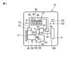
本発明の第1の実施形態に係るハイブリッド車両を、図1〜6を用いて説明する。図1は、ハイブリッド車両の一例である、ハイブリッド電気自動車10の構成を示す概略図である。図1に示すように、ハイブリッド電気自動車10は、走行用の電動機20と、内燃機関60と、電動機20の回転数を走行に適した回転数に変換する電動機用変速機30と、内燃機関60の出力軸の回転数を走行に適した回転数に変換する内燃機関用変速機130と、電動機用インバータ40と、発電機50と、内燃機関60と、発電機用インバータ70と、電池80と、BMU(Battery Management Unit)90と、内燃機関用制御部100と、アクセル開度検出部140と、ハイブリッド電気自動車10の全体を統括する制御部110とを備えている。 A hybrid vehicle according to a first embodiment of the present invention will be described with reference to FIGS. FIG. 1 is a schematic diagram illustrating a configuration of a hybrid
電動機20が発生する動力、言い換えると電動機20の出力軸の回転は、電動機用変速機30によって変速された後、車輪5に伝達される。図中は、車輪5は、1つのみ記載されているが、ハイブリッド電気自動車10は、実際は、一対の前輪と、一対の後輪とを備えている。車輪5は、これら、前輪と後輪とを含む概念である。 The power generated by the
電動機20は、電動機用インバータ40を介して、電池80から電力が供給される。電動機20は、電池80から供給された電力によって駆動する。電池80は、複数の電池セル81を備えており、これら電池セル81が例えば直列接続されることによって、構成されている。 Electric power is supplied from the
各電池セル81には、CMU(Cell Monitor Unit)82が設けられている。CMU82は、電池セル81の状態を検出する。電池セル81の状態とは、電池セル81の温度、電池セル81の電圧、電池セル81の放電電流である。 Each
BMU90は、各CMU82に接続されており、各CMU82の検出結果が送信される。BMU90は、各CMU82の検出結果より、複数の電池セル81の温度のうち最も低い温度の電池セル81の温度を電池80の温度として設定するとともに、複数の電池セル81の電圧のうち最も低い電圧値を、電池セル81の電圧値として設定する。BMU90は、複数の電池セル81の放電電流値から電池80全体の放電電流を算出する。また、BMU90は、電池セル81の電圧値に基づいて、電池80の充電率(SOC:State Of Charge)を検出する。 The BMU 90 is connected to each
内燃機関60は、例えばガソリンなどの燃料を燃焼することによって動力を発生する、言い換えると出力軸を回転する。内燃機関60は、発電機50を駆動するための動力装置として用いられるとともに、車輪5を回転して走行するための走行用の駆動源として用いられる。 The
内燃機関60の出力軸と発電機の回転軸とは、伝達機構51を介して、互いに連結されており、内燃機関60の出力軸の回転が、発電機50の回転軸に伝達される。このことによって、発電機50が駆動される。発電機50は、駆動されることによって、発電する。発電機50が発電した電力は、発電機用インバータ70を介して、電動機用インバータ40に供給される。 The output shaft of the
発電機50は、上記のように、内燃機関60によって駆動されて発電する機能の他に、内燃機関60のスタータとして機能する。具体的には、内燃機関60の動作が停止している状態、つまり内燃機関60の出力軸が回転していない状態で発電機50が動作すると、発電機50の軸の回転が伝達機構51を介して内燃機関60の出力軸に伝達される。このことによって、内燃機関60が始動する。 The
内燃機関用制御部100は、後述される制御部110からの指示によって、内燃機関60の燃焼室内に供給される燃料の量などの制御を行う。 The internal combustion
内燃機関60の出力を、発電ではなく車輪5に伝達する場合、内燃機関60の出力軸の回転は、内燃機関用変速機130を介して車輪5に伝達される。内燃機関用変速機130内には、クラッチ装置150が設けられている。クラッチ装置150は、クラッチ板151,152と、クラッチ板駆動部153とを備えている。 When the output of the
クラッチ板151とクラッチ板152とは、内燃機関用変速機130内の、内燃機関60の出力軸の回転が伝達する伝達経路C内に設けられている。クラッチ板151とクラッチ板152とが互いに接触していない状態は、伝達経路Cが切断されている状態であり、それゆえ、内燃機関60の出力軸の回転は、車輪5に伝達されない。 The clutch plate 151 and the
クラッチ板151とクラッチ板152とが互いに接触している状態では、クラッチ板151とクラッチ板152とが互いに一体に回転することによって伝達経路Cが接続状態になり、それゆえ、内燃機関60の回転軸の回転は、車輪5に伝達される。 In a state where the clutch plate 151 and the
クラッチ板駆動部153は、クラッチ板151とクラッチ板152とを互いに接触するべく動作するとともに、クラッチ板151とクラッチ板152とが離間するように動作する。 The clutch
上記構成を有するハイブリッド電気自動車10は、走行モードとして、第1の走行モードと、第2の走行モードとを有する。第1の走行モードは、内燃機関60は駆動せず、電池80から供給される電力によってのみ電動機20が駆動することによって走行する走行モードである。 The hybrid
第2の走行モードは、電池80から電動機20に電力が供給されて電動機20が駆動するとともに、クラッチ板151,152が接続されて車輪5の回転をアシストするために内燃機関60が駆動する走行モードである。なお、本実施形態の第2の走行モードでは、一例として、発電機50を駆動する場合と、駆動しない場合とがある。 In the second traveling mode, electric power is supplied from the
第2の走行モードにおいて、電池80のSOCが充電開始閾値以下になると、後述される制御部110の制御によって、発電機50と発電機用インバータ70とが制御されて、発電される。なお、第2の走行モードになると、常に発電機で充電するようにしてもよい。 In the second traveling mode, when the SOC of the
制御部110は、アクセル開度検出部140から検出結果が送信される。アクセル開度検出部140は、アクセルペダルの踏み込み量を検出する。アクセルペダルは、ハイブリッド電気自動車10を走行する際に運転者が踏み込むペダルである。制御部110は、アクセル開度検出部140の検出結果を受けて、検出結果に応じた走行ができるように電池80に対して要求する出力値を算出する。この出力を第1の出力値とする。 The
制御部110は、BMU90の検出結果が送信される。制御部110は、BMU90からの受信結果に基づいて、電池80の電池セル81の電圧値と、電池80の電流値とから、電池80が出力できる最大値である第2の出力値を算出する。第2の出力値は、放電中の電池セルの電圧値に、電池80が放電している電流値を乗算したものです。 The
また、制御部110は、電池80のSOCに応じて、第1の走行モードから、第2の走行モードへ移行するべく、走行に係る走行システム200を制御する。走行に係るシステム200とは、車輪5、内燃機関60と、電動機20と、発電機50と、電池80と、電動機用インバータ40と、発電機用インバータ70と、内燃機関用制御部100とである。走行システム200は、ハイブリッド電気自動車10を走行可能とするための手段の一例である。
具体的には、ハイブリッド電気自動車10は、電池80のSOCが、予め設定される閾値より大きい場合では、第1の走行モードで走行するべく、内燃機関60は駆動せず、電動機20を駆動するとともに電動機用インバータ40を制御する。電動機用インバータ40は、制御部110から要求される第1の出力値を、つまり電池80から電動機20に供給すべき第1の出力値を電池80から電動機20に出力するべく動作する。 Specifically, the hybrid
制御部110は、電池80のSOCが閾値以下になると、第2の走行モードで走行するべく、発電機用インバータ70を制御して発電機50をスタートとして駆動して内燃機関60を駆動する。さらに、クラッチ板駆動部153を制御して、クラッチ板151とクラッチ板152とを接続状態にする。なお、電池80のSOCが、上記した充電開始閾値以下になっていない場合では、発電機50はスタータとして用いられた後は動作を停止し、発電することはない。 When the SOC of the
そして、内燃機関60は、電池80に要求される第1の出力値に対する電池80が出力可能な第2の出力値の不足分を補い、ハイブリッド電気自動車10が、アクセル開度検出部の検出結果に応じた走行を可能とするように、運転される。内燃機関60の運転状態と、内燃機関60による出力のアシスト量との関係は、事前に実験などによって求められており、記憶部120に記憶されている。制御部110は、記憶部120に記憶されている情報に基づいて、内燃機関用制御部100を制御する。このことによって、内燃機関用制御部100は、上記のように内燃機関60の運転を制御する。 Then, the
第1の走行モードから第2の走行モードに切り替える閾値は、電池80の劣化状態によって変化する。記憶部120は、電池80の劣化状態に応じた閾値を示す劣化―充電率マップを記憶している。マップは、アクセル開度ごとに設定されている
本実施形態では、アクセル開度は、一例として、小状態、中状態、大状態の3つの状態に分けられている。なお、アクセル開度状態は、例えば、より細かく分けられてもよい。アクセル開度状態のわけ方は、複数のグループに分けられればよい。アクセルペダルの踏み込み量と小状態と中状態と大状態との関係は、予め、決定されており、記憶部120に記憶されている。制御部110は、アクセル開度検出部140の検出結果に基づいてアクセル開度状態を選択する。The threshold value for switching from the first travel mode to the second travel mode varies depending on the deterioration state of the
また、各アクセル開度状態に設定される劣化―充電率マップは、温度に応じて分けられている。本実施形態では、温度は、一例として5つの範囲に分けられている。なお、温度を5つの範囲に分けることは、温度を複数の範囲に分けることの一例である。例えば、6、7つの範囲に分けてもよい。 Further, the deterioration-charge rate map set for each accelerator opening state is divided according to the temperature. In this embodiment, the temperature is divided into five ranges as an example. Note that dividing the temperature into five ranges is an example of dividing the temperature into a plurality of ranges. For example, it may be divided into 6 or 7 ranges.
第1の温度範囲は、25℃より大きい範囲である。第2の温度範囲は、10℃より大きく、かつ、25℃以下の範囲である。第3範囲は、0℃より大きくかつ、10℃以下の範囲である。第4の温度範囲は、−10℃より大きく、かつ、0℃以下の範囲である。第5の範囲は、−25℃より大きく、かつ、−10℃以下の範囲である。 The first temperature range is a range greater than 25 ° C. The second temperature range is greater than 10 ° C and less than or equal to 25 ° C. The third range is a range greater than 0 ° C. and 10 ° C. or less. The fourth temperature range is greater than −10 ° C. and less than or equal to 0 ° C. The fifth range is a range greater than −25 ° C. and not greater than −10 ° C.
本実施形態では、各アクセル開度状態に設定される劣化―充電率マップは、温度の各範囲に設定された部分を全て含む概念である。このため、異なる劣化―充電率マップとは、異なるアクセル開度状態の劣化―充電率マップを示す。 In the present embodiment, the deterioration-charge rate map set for each accelerator opening state is a concept including all the portions set for each range of temperature. For this reason, different deterioration-charge rate maps indicate deterioration-charge rate maps of different accelerator opening states.
図2は、アクセル開度が小状態のときに用いられる小状態用劣化―充電率マップM1を示している。小状態用劣化―充電率マップM1は、第1の温度範囲のときに用いられる第1の温度範囲用参照部131aと、第2の温度範囲のときに用いられる第2の温度範囲用参照部132aと。第3の温度範囲のときに用いられる第3の温度範囲用参照部133aと、第4の温度範囲のときに用いられる第4の温度範囲用参照部134aと、第5の温度範囲のときに用いられる第5の温度範囲用参照部135aとを備えている。 FIG. 2 shows a small-state deterioration-charge rate map M1 used when the accelerator opening is in a small state. The small-state deterioration-charge rate map M1 includes a first temperature
小状態用劣化―充電率マップM1の横軸は、劣化判定度合い値を示している。縦軸は、電池80のSOCを示している。縦軸は、矢印に沿って進むにつれて、値が大きくなる。 The horizontal axis of the small state deterioration-charge rate map M1 represents the deterioration determination degree value. The vertical axis represents the SOC of the
図2に示すように、小状態用劣化―充電率マップM1は、第1の走行モードから第2の走行モードに移行する閾値となる電池80のSOCを、電池80の劣化判定度合い値ごとに示している。本実施形態では、一例として、劣化判定度合い値は、1〜13まで設定している。劣化判定度合い値1は、新品の状態であり、劣化判定度合い値13は、劣化が最も進んだ状態である。劣化判定度合い値が上がるにつれて、電池80の劣化が進んでいることを示す。 As shown in FIG. 2, the small-state deterioration-charge rate map M1 indicates the SOC of the
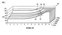
図3は、アクセル開度が中状態のときに用いられる中状態用劣化―充電率マップM2を示している。中状態用劣化―充電率マップM2は、第1の温度範囲のときに用いられる第1の温度範囲用参照部131bと、第2の温度範囲のときに用いられる第2の温度範囲用参照部132bと。第3の温度範囲のときに用いられる第3の温度範囲用参照部133bと、第4の温度範囲のときに用いられる第4の温度範囲用参照部134bと、第5の温度範囲のときに用いられる第5の温度範囲用参照部135bとを備えている。 FIG. 3 shows a middle state deterioration-charge rate map M2 used when the accelerator opening is in the middle state. The deterioration for middle state-charge rate map M2 includes a first temperature
中状態用劣化―充電率マップM2の横軸と縦軸とは、小状態用劣化―充電率マップM1と同じである。 The horizontal and vertical axes of the medium state deterioration-charge rate map M2 are the same as the small state deterioration-charge rate map M1.
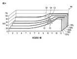
図4は、アクセル開度が大状態のときに用いられる大状態用劣化―充電率マップM3を示している。大状態用劣化―充電率マップM3は、第1の温度範囲のときに用いられる第1の温度範囲用参照部131cと、第2の温度範囲のときに用いられる第2の温度範囲用参照部132cと。第3の温度範囲のときに用いられる第3の温度範囲用参照部133cと、第4の温度範囲のときに用いられる第4の温度範囲用参照部134cと、第5の温度範囲のときに用いられる第5の温度範囲用参照部135cとを備えている。 FIG. 4 shows a large state deterioration-charge rate map M3 used when the accelerator opening is in a large state. The large-state deterioration-charge rate map M3 includes a first temperature
大状態用劣化―充電率マップM3の横軸と縦軸は、小状態用劣化―充電率マップM1と同じである。 The horizontal axis and the vertical axis of the large state deterioration-charge rate map M3 are the same as the small state deterioration-charge rate map M1.
図2〜4に示すように、閾値は、電池80の劣化状態に応じて変化する。ここで、電池80の劣化について、説明する。電池80は、充電と放電とを繰り返すことによって、劣化する。劣化することによって、同じSOCの値であっても、電池80からの出力が低下する。より具体的には、例えば、SOCが60パーセントであっても、新品の状態で電池80からの出力に対して、劣化が進んだ状態での出力は、小さくなる。 As shown in FIGS. 2 to 4, the threshold value changes according to the deterioration state of the
このため、小状態用劣化―充電率マップM1の各参照部131a〜135aの各々、中状態用劣化―充電率マップM2の各参照部131b〜135bの各々、大状態用劣化―充電率マップM3の各参照部131c〜135cの各々において、新品時から劣化が進むにつれて、第1の走行モードから第2の走行モードに移行する閾値が、大きくなる。 For this reason, each of the
また、各アクセル開度状態においていずれの劣化判定度合い値であっても、温度が高い温度範囲になるほど閾値は小さくなる。このため、温度が高い温度範囲になるほど、閾値の変化の幅は、大きくなる。この点について具体的に説明する。まず、アクセル開度が小状態のときについて、説明する。 In addition, the threshold value becomes smaller as the temperature is higher in any deterioration determination degree value in each accelerator opening state. For this reason, the width of the change in the threshold value increases as the temperature increases. This point will be specifically described. First, the case where the accelerator opening is small will be described.
アクセル開度が小状態であり、電池80の温度が第1の温度範囲内にあるとき、つまり、小状態用劣化―充電率マップM1の第1の温度範囲用参照部131aが示すように、新品の状態での閾値は、40パーセントである。第2の温度範囲では、第2の温度範囲用参照部132aが示すように、新品の状態での閾値は、48パーセントである。第3の温度範囲では、第3の温度範囲用参照部133aが示すように、新品の状態での閾値は、56パーセントである。第4の温度範囲では、第4の温度範囲用参照部134aが示すように、新品の状態での閾値は、62パーセントである。第5の温度範囲では、第5の温度範囲用参照部135aが示すように、新品の状態での閾値は、78パーセントである。 When the accelerator opening is in a small state and the temperature of the
このように、温度が高い温度範囲の方が、劣化判定度合い値が1のときの閾値が小さくなるので、温度が温度範囲の方が閾値の変化の幅が大きくなる。いずれの劣化判定度合い値であっても、上記と同様になる。 As described above, the temperature range in which the temperature is higher has a smaller threshold value when the deterioration determination degree value is 1. Therefore, the range of change in the threshold value is larger in the temperature range of temperature. Any deterioration determination degree value is the same as described above.
つぎに、アクセル開度が中状態のときについて説明する。図3に示すように、第1の温度範囲では、第1の温度範囲用参照部131bが示すように、新品の状態での閾値は、32パーセントである。第2の温度範囲では、第2の温度範囲用参照部132bが示すように、新品の状態での閾値は、37パーセントである。第3の温度範囲では、第3の温度範囲用参照部133bが示すように、新品の状態での閾値は、44パーセントである。第4の温度範囲では、第4の温度範囲用参照部134bが示すように、新品の状態での閾値は、52パーセントである。第5の温度範囲では、第5の温度範囲用参照部135bが示すように、新品の状態での閾値は、70パーセントである。 Next, the case where the accelerator opening is in the middle state will be described. As shown in FIG. 3, in the first temperature range, as indicated by the first temperature
このように、温度が高い温度範囲の方が、劣化判定度合い値が1のときの閾値が小さくなるので、温度が高い温度範囲の方が閾値の変化の幅が大きくなる。いずれの劣化判定度合い値であっても、上記と同様になる。 As described above, the temperature range in which the temperature is higher has a smaller threshold value when the deterioration determination degree value is 1. Therefore, the range of change in the threshold value is larger in the temperature range in which the temperature is higher. Any deterioration determination degree value is the same as described above.
つぎに、アクセル開度が大状態のときについて説明する。図4に示すように、第1の温度範囲では、第1の温度範囲用参照部131cが示すように、新品状態での閾値は、20パーセントである。第2の温度範囲では、第2の温度範囲用参照部132cが示すように、新品状態での閾値は、28パーセントである。第3の温度範囲では、第3の温度範囲用参照部133cが示すように、新品状態での閾値は、36パーセントである。第4の温度範囲では、第4の温度範囲用参照部134cが示すように、新品状態での閾値は、42パーセントである。第5の温度範囲では、第5の温度範囲用参照部135cが示すように、新品状態での閾値は、58パーセントである。 Next, the case where the accelerator opening is in a large state will be described. As shown in FIG. 4, in the first temperature range, as indicated by the first temperature
このように、温度が高い温度範囲の方が、劣化判定度合い値が1のときの閾値が小さくなるので、温度が高い温度範囲の方が閾値の変化の幅が大きくなる。いずれの劣化判定度合い値であっても、上記と同様になる。 As described above, the temperature range in which the temperature is higher has a smaller threshold value when the deterioration determination degree value is 1. Therefore, the range of change in the threshold value is larger in the temperature range in which the temperature is higher. Any deterioration determination degree value is the same as described above.
また、各アクセル開度状態において、いずれの劣化判定度合い値であっても、低い温度の温度範囲になるほど、閾値は大きくなる。一例を具体的に説明する。例えば、アクセル開度が小状態であって劣化判定度合い値が10であるとき、第1の温度範囲のときの閾値よりも第2の温度範囲のときの閾値の方が大きく、第2の温度範囲のときの閾値よりも第3の温度範囲のときの閾値の方が大きく、第3の温度範囲のときの閾値よりも第4の温度範囲のときの閾値の方が大きく、第4の温度範囲のときの閾値よりも第5の温度範囲のときの閾値の方が大きい。上記したように、このことは、いずれのアクセル開度状態のいずれの劣化判定度合い値であっても、同じである。 Further, in each accelerator opening state, the threshold value increases as the temperature range becomes lower, regardless of the deterioration determination degree value. An example will be specifically described. For example, when the accelerator opening is small and the deterioration determination degree value is 10, the threshold value in the second temperature range is larger than the threshold value in the first temperature range, and the second temperature The threshold value for the third temperature range is greater than the threshold value for the range, the threshold value for the fourth temperature range is greater than the threshold value for the third temperature range, and the fourth temperature. The threshold value in the fifth temperature range is larger than the threshold value in the range. As described above, this is the same regardless of the deterioration determination degree value in any accelerator opening state.
また、温度が低い温度範囲になるほど、閾値の変化の傾きが大きくなる。この点について、具体的に説明する。まず、アクセル開度が小状態のときについて説明する。図2に示すように、各参照部131a〜135aでは、いずれも、劣化判定度合い値6に達すると閾値が高くなり始める。そして、第1の温度範囲用参照部131aでは、劣化判定度合い値12になると、閾値が100パーセントになる。第2の温度範囲用参照部132aでは、劣化判定度合い値12になると、閾値が100パーセントになる。第3の温度範囲用参照部133aでは、劣化判定度合い値10になると、閾値が100パーセントになる。第4の温度範囲用参照部134aでは、劣化判定度合い値9になると、閾値が100パーセントになる。第5の温度範囲用参照部135aでは、劣化判定度合い値8になると、閾値が100パーセントになる。 Further, the lower the temperature range, the greater the slope of the change in threshold value. This point will be specifically described. First, the case where the accelerator opening is small will be described. As illustrated in FIG. 2, in each of the
第1の温度範囲用参照部131aにおいて、閾値が上がり始めてから100パーセントに達するまでの変化の平均を示す傾きをA1とし、第2の温度範囲用参照部132aにおいて閾値が上がり始めてから100パーセントに達するまでの変化の平均を示す傾きをA2とし、第3の温度範囲用参照部133aにおいて閾値が上がり始めてから100パーセントに達するまでの変化の平均を示す傾きをA3とし、第4の温度範囲用参照部134aにおいて閾値が上がり始めてから100パーセントに達するまでの変化の平均を示す傾きをA4とし、第5の温度範囲用参照部135aにおいて閾値が上がり始めてから100パーセントに達するまでの変化の平均を示す傾きをA5とすると、A1<A2<A3<A4<A5となる。このように、電池80の温度が低くなるにつれて、劣化の進みかたに対する閾値の変化量が大きくなることがわかる。閾値の変化の傾きは、劣化の進み方に対する閾値の変化を示す。 In the first temperature
また、各温度範囲用参照部131a〜135aは、劣化度合い値が大きくなるにつれて、閾値の増加量も大きくなる。このことは、劣化判定度合い値が大きくなるにつれて閾値の上昇率が大きくなることを示す。 In addition, each of the temperature
つぎに、アクセル開度が中状態について説明する。アクセル開度が中状態のときについて説明する。図3に示すように、各第1〜5の温度範囲用参照部131b〜135bでは、いずれも、劣化判定度合い値6近傍で閾値が高くなり始める。そして、第1の温度範囲用参照部131bでは、劣化判定度合い値11になると、閾値が100パーセントになる。第2の温度範囲用参照部132bでは、劣化判定度合い値11になると、閾値が100パーセントになる。第3の温度範囲用参照部133bでは、劣化判定度合い値9になると、閾値が100パーセントになる。第4の温度範囲用参照部134bでは、劣化判定度合い値8になると、閾値が100パーセントになる。第5の温度範囲用参照部135aでは、劣化判定度合い値7になると、閾値が100パーセントになる。 Next, a description will be given of a state where the accelerator opening is in the middle state. The case where the accelerator opening is in the middle state will be described. As shown in FIG. 3, in each of the first to fifth temperature
第1の温度範囲用参照部131bにおいて、閾値が上がり始めてから100パーセントに達するまでの変化の平均を示す傾きをB1とし、第2の温度範囲用参照部132bにおいて閾値が上がり始めてから100パーセントに達するまでの変化の平均を示す傾きをB2とし、第3の温度範囲用参照部133bにおいて閾値が上がり始めてから100パーセントに達するまでの変化の平均を示す傾きをB3とし、第4の温度範囲用参照部134bにおいて閾値が上がり始めてから100パーセントに達するまでの変化の平均を示す傾きをB4とし、第5の温度範囲用参照部135bにおいて閾値が上がり始めてから100パーセントに達するまでの変化の平均を示す傾きをB5とすると、B1<B2<B3<B4<B5となる。このように、電池80の温度が低くなるにつれて、劣化の進みかたに対する閾値の変化の割合が大きくなることがわかる。 In the first temperature
また、各温度範囲用参照部131b〜135bは、劣化度合い値が大きくなるにつれて、閾値の増加量が大きくなる。このことは、劣化判定度合い値が大きくなるに従い閾値の上昇率が大きくなることを示す。 In addition, each of the temperature
つぎに、アクセル開度が大状態のときについて説明する。図4に示すように、各参照部131c〜135cでは、いずれも、劣化判定度合い値6に達すると閾値が高くなり始める。そして、第1の温度範囲用参照部131cでは、劣化判定度合い値12になると、閾値が100パーセントになる。第2の温度範囲用参照部132cでは、劣化判定度合い値12になると、閾値が100パーセントになる。第3の温度範囲用参照部133cでは、劣化判定度合い値10になると、閾値が100パーセントになる。第4の温度範囲用参照部134cでは、劣化判定度合い値9になると、閾値が100パーセントになる。第5の温度範囲用参照部135cでは、劣化判定度合い値8になると、閾値が100パーセントになる。 Next, the case where the accelerator opening is in a large state will be described. As illustrated in FIG. 4, in each of the
第1の温度範囲用参照部131cにおいて、閾値が上がり始めてから100パーセントに達するまでの変化の平均を示す傾きをC1とし、第2の温度範囲用参照部132cにおいて閾値が上がり始めてから100パーセントに達するまでの変化の平均を示す傾きをC2とし、第3の温度範囲用参照部133cにおいて閾値が上がり始めてから100パーセントに達するまでの変化の平均を示す傾きをC3とし、第4の温度範囲用参照部134cにおいて閾値が上がり始めてから100パーセントに達するまでの変化の平均を示す傾きをC4とし、第5の温度範囲用参照部135cにおいて閾値が上がり始めてから100パーセントに達するまでの変化の平均を示す傾きをC5とすると、C1<C2<C3<C4<C5となる。このように、電池80の温度が低くなるにつれて、劣化の進みかたに対する閾値の変化の割合が大きくなることがわかる。 In the first temperature
また、各温度範囲用参照部131c〜135cは、劣化度合い値が大きくなるにつれて、閾値の増加量が大きくなる。このことは、劣化判定度合い値が大きくなるに従い閾値の上昇率が大きくなることを示す。 Further, each of the temperature
制御部110の説明に戻る。制御部110は、第1の出力値が第2の出力値より大きくなったことを検出すると、電池80の劣化判定度合い値が1つあがったと判定して、電池80の劣化判定度合い値を更新する。 Returning to the description of the
このように、劣化判定度合い値が変更されることによって、閾値が変更される。このように、変更前と変更後という相対関係において、変更前の閾値を第1の閾値とし、当該第1の閾値に対して変更された後の閾値を第2の閾値とする。また、劣化判定度合い値に変更がなくても、温度範囲が変化することによって閾値が変化する。劣化判定度合い値が変更しないときの低い温度範囲への変更前と変更後という相対関係において、変更前の閾値を第1の閾値とし、低い温度範囲への変更後の閾値を第2の閾値とする。 Thus, the threshold value is changed by changing the deterioration determination degree value. As described above, in the relative relationship before and after the change, the threshold before the change is set as the first threshold, and the threshold after the change with respect to the first threshold is set as the second threshold. Even if the deterioration determination degree value is not changed, the threshold value changes as the temperature range changes. In the relative relationship between before and after the change to the low temperature range when the deterioration determination degree value does not change, the threshold value before the change is set as the first threshold value, and the threshold value after the change to the low temperature range is set as the second threshold value. To do.
また、制御部110は、いずれかのアクセル開度状態において閾値が第1の閾値から第2の閾値に更新された後、つまり、劣化判定度合い値が更新された後、アクセル開度状態が異なる状態に変更されると、閾値としては、第1の閾値に対応する劣化判定度合い値に対応する値を用いる。言い換えると、更新前の劣化判定度合い値に対応する閾値を用いる。 In addition, after the threshold value is updated from the first threshold value to the second threshold value in any accelerator opening state, that is, after the deterioration determination degree value is updated, the
上記したように、アクセル開度状態が大きくなるように変化した場合、例えば、小状態から中状態に変化した場合、または、中状態から大状態に変化した場合、同じ劣化判定度合い値であっても、閾値は、下がる。 As described above, when the accelerator opening state changes so as to increase, for example, when the small state changes to the middle state, or when the intermediate state changes to the large state, the same deterioration determination degree value is obtained. However, the threshold is lowered.
このため、第1の閾値から第2の閾値に変更された後にアクセル開度状態が変更された場合、アクセル開度状態の変更後においては第1の閾値に対応する劣化判定度合い値に対応する値を用いても、電池80のそのときの充電率は、第1の閾値に対応する劣化判定度合い値に対応する値より大きい場合がある。 For this reason, when the accelerator opening state is changed after being changed from the first threshold value to the second threshold value, it corresponds to the deterioration determination degree value corresponding to the first threshold value after the change of the accelerator opening state. Even if the value is used, the current charging rate of the
このような場合では、第1の閾値に対応する劣化判定度合い値に対応する値を閾値として用いても、第1の走行モードが維持されるので、電池80の電力を有効に利用することができる。つまり、燃費を向上することができる。このような場合に、閾値として第2の閾値に対応する劣化判定度合い値に対応する値がそのまま用いられていると、電池80としては第1の走行モードで走行することが十分可能な状態にも関わらず、第2の走行モードに移行してしまい、電池80の電力を有効に用いなくなってしまう。 In such a case, even if the value corresponding to the deterioration determination degree value corresponding to the first threshold value is used as the threshold value, the first traveling mode is maintained, so that the power of the
さらに言いかえると、制御部110は、あるアクセル開度状態において劣化判定度合い値が大きくなるように変化した後にアクセル開度状態が変更すると、電池80の劣化判定度合い値は、上記変更前の値に戻す。 In other words, when the accelerator opening state changes after the change so that the deterioration determination degree value increases in a certain accelerator opening state, the
具体的な例で説明する。一例として、アクセル開度状態が中状態であるときに、劣化判定度合い値が6から7に変化したとする。このとき、劣化判定度合い値が6のときの閾値が第1の閾値となり、劣化判定度合い値が7のときの閾値が第2の閾値となる。アクセル開度状態が中状態では、中状態用劣化―充電率マップM2に示される劣化判定度合い値7の閾値を用いる
そして、劣化判定度合い値7に変更された後、アクセル開度状態が中状態から大状態に変更される。アクセル開度が大状態に変更されるときに用いる閾値は、大状態用劣化―充電率マップM3に示される劣化判定度合い値が7の閾値ではなく、第1の閾値に対応する劣化判定度合い値に対応する値である。つまり、第1の閾値に対応する劣化判定度合い値は6であり、アクセル開度が大状態に変更されたときには、大状態用劣化―充電率マップM3に示される劣化判定度合い値が6の閾値を用いる。A specific example will be described. As an example, it is assumed that the deterioration determination degree value changes from 6 to 7 when the accelerator opening state is the middle state. At this time, the threshold value when the deterioration determination degree value is 6 is the first threshold value, and the threshold value when the deterioration determination degree value is 7 is the second threshold value. When the accelerator opening state is in the middle state, the threshold value of the deterioration
図5は、制御部110の動作を示すフローチャートである。図6は、動作を示すブロック図である。図5,6を用いて制御部110の動作を説明する。走行開始後、図5に示すように、制御部110は、ステップST1で、アクセル開度検出部140の検出結果に基づいて、アクセルペダルが踏み込まれたことを検出すると、ステップST2に進む。アクセルペダルの開度が0、つまり、アクセルペダルが踏み込まれていない状態では、ハイブリッド電気自動車10に対して走行の要求がない状態である。アクセル開度が0の場合は、再びステップST1に戻る。 FIG. 5 is a flowchart showing the operation of the
ステップST2では、制御部110は、アクセル開度検出部140の検出結果に基づいて電池80に対して要求する第1の出力値を算出する。ついで、ステップST3に進む。この処理は、図6においてブロックBK1で示されている。 In step ST <b> 2,
ステップST3では、制御部110は、BMU90の検出結果に基づいて、電池80が出力可能な第2の出力値を算出する。第2の出力値は、電池セル81の電圧値に、電池80の放電電流を乗算したものである。つまり、(第2の出力値)=(放電中のセル電圧値)×(電池80全体の放電電流)となる。演算が終了すると、ついで、ステップST4に進む。この処理は、図6において、ブロックBK2で示されている。 In step ST <b> 3, the
ステップST4では、制御部110は、ステップST2で算出された第1の出力値と、ステップST3で算出された第2の出力値との出力値差を演算する。出力差値は、第2の出力から第1の出力値を除算して求められる。つまり、(出力差)=(第2の出力値)−(第1の出力値)となる。この処理は、図6においてブロックBK3で示されている。演算が終了すると、ついで、ステップST5に進む。 In step ST4, the
ステップST5では、制御部110は、ステップST4で算出した出力差が0以上であるか否かを判定する。出力差が0以上ということは、電池80は、要求された第1の出力値を出力することができるということである。出力差が0未満の場合は、電池80は、要求される第1の出力値を出力することができない状態である。出力差が0未満の場合は、電池80が劣化したことを示す。 In step ST5,
まず、出力差が0以上である場合を説明する。制御部110は、出力差が0以上であると判定すると、ついで、ステップST7に進む。ステップST7では、制御部110は、アクセル開度状態が変更されたか否かを判定する。アクセル開度状態が変更された場合は、ステップST8に進む。ステップST8では、制御部110は、劣化判定度合い値を、前回の値に戻す。言い換えると、第1の閾値に対応する劣化判定度合い値に戻す。 First, a case where the output difference is 0 or more will be described. If
これは、上述したように、アクセル開度状態が変更することによって、第1の閾値に対応する劣化判定度合い値に対応する値を閾値とすることによって、電池80の電力を有効にしようできる場合があるためである。 As described above, when the accelerator opening state is changed, the value corresponding to the deterioration determination degree value corresponding to the first threshold value is used as the threshold value, so that the power of the
ステップST7において、制御部110は、アクセル開度状態が変更されていないと判定すると、ステップST9に進む。ステップST9では、制御部110は、劣化―充電率マップM1〜M3の中から、アクセル開度状態に対応する劣化―充電率マップを選択する。選択すると、ついで、ステップST10に進む
ステップST10では、制御部110は、ステップST9で選択した劣化―充電率マップのうち対応する温度範囲の参照部を参照して、電池80のSOCが閾値以下になっているか否かを判定する。SOCが閾値より大きい場合はステップST11に進み、SOCが閾値以下である場合は、ステップST12に進む。In step ST7, if the
ステップST11では、制御部110は、第1の走行モードを選択し、第1の走行モードで走行するべく、走行システム200を制御する。ステップST12では、第2の走行モードを選択し、第2の走行モードで走行するべく、走行システム200を制御する。ステップST11,ST12の処理が終了すると、ついで、ステップST1に戻る。 In step ST11, the
つぎに、ステップST5で、出力差が0未満であると判定した場合を説明する。出力差が0未満の場合は、電池80は、制御部110が要求する出力値を出力可能な状態である。このため、ステップST5からステップST6に進む。ステップST6では、劣化判定度合い値を1つ上げる。この処理は、図6においてブロックBK4で示されている。 Next, the case where it is determined in step ST5 that the output difference is less than 0 will be described. When the output difference is less than 0, the
このように構成されるハイブリッド電気自動車10では、電池80の劣化度合い値が大きくなるに従い、閾値として用いる充電率の値を大きくするので、電池80の劣化進むことによって、電池80の出力が低下しても、内燃機関60のアシストを加えることによって、ハイブリッド電気自動車10の走行に必要な出力を確保することができる。このため、車両動力性能が低下することを抑制できる。 In the hybrid
また、劣化判定度合い進行を判定するために、第1,2の出力値を比較する。第1,2の出力値を比較することは、電池80が、走行に要する出力をまかなえるか否かを判定することであるので、このように判定された劣化判定度合い値は、ハイブリッド電気自動車10の車両動力性能の低下を抑制するために有効である。 Further, the first and second output values are compared to determine the progress of the deterioration determination degree. Since the comparison between the first and second output values is to determine whether or not the
また、あるアクセル開度状態で劣化判定度合い値が更新された後にアクセル開度状態が変化して用いる劣化―充電率マップが変更されると、第1の閾値、つまり上記更新前の閾値に対応する劣化判定度合い値に対応する値が閾値として用いられる。さらに言い換えると、更新前の劣化判定度合い値の閾値が用いられる。このため、電池80の電量を有効に利用することができる。 Also, when the deterioration-charging rate map is changed after the accelerator opening state changes after the deterioration determination degree value is updated in a certain accelerator opening state, it corresponds to the first threshold, that is, the threshold before the update. A value corresponding to the deterioration determination degree value to be used is used as a threshold value. In other words, the threshold value of the deterioration determination degree value before update is used. For this reason, the electric charge of the
また、各温度範囲用参照部131a〜135a,131b〜135b,131c,135cは、電池80の温度に対する特性に対応するべく、温度範囲が低くなるに従い、閾値をより大きい値に変更している。 Further, each of the temperature
このため、電池80の特性に合わせて閾値が変更されるようになり、運転者の要求出力に合致する出力を、電動機20から出すことができる。 For this reason, the threshold value is changed according to the characteristics of the
また、電池80の温度が低くなるに従って、第1の閾値を高く設定するとともに、前記第1の閾値の上昇率を大きくしている。つまり、傾きA1,A2,A3,A4,A5はこの順番に沿って大きくなり、傾きB1,B2,B3,B4,B5は、この順番に沿って大きくなり、傾きC1,C2,C3,C4,C5は、この順番に沿って大きくなる。これは、各マップを、電池80の特性の変化に合わせるものである。言い換えると、各マップを電池80の特性に合わせていることにより、電池80を有効に利用することができる。 Further, as the temperature of the
つぎに、本発明の第2の実施形態に係るハイブリッド車両を、図7,8を用いて説明する。なお、第1の実施形態と同様の機能を有する構成は、第1の実施形態と同一の符号を付して説明を省略する。本実施形態では、制御部110の動作が異なる。ハイブリッド電気自動車の構造は、第1の実施形態と同じである。上記異なる点について説明する。 Next, a hybrid vehicle according to a second embodiment of the present invention will be described with reference to FIGS. In addition, the structure which has the same function as 1st Embodiment attaches | subjects the code | symbol same as 1st Embodiment, and abbreviate | omits description. In the present embodiment, the operation of the
図7は、本実施形態の制御部110の動作を示すフローチャートである。図8は、本実施形態での動作を示すブロック図である。図7,8に示すように、本実施形態では、ステップST5に代えて、ステップST13が用いられる。ステップST3では、制御部110は、出力差が、予め設定される所定値より大きいか否かを判定する。所定値をαとすると、(第2の出力値)−(第1の出力値)>αが成り立つか否かを判定する。この処理は、図8においてブロックBK5で示されている。 FIG. 7 is a flowchart showing the operation of the
所定値αは、制御部110が出力差を算出するために必要なデータを検出する検出部の検出誤差を吸収するために予め決定される値であり、実験などによって求めることができる。つまり、所定値αは、劣化判定出力差である。 The predetermined value α is a value determined in advance in order to absorb the detection error of the detection unit that detects data necessary for the
本実施形態では、第1の形態の効果に加えて、出力差の検出誤差などを吸収することができる。検出誤差は、例えば、アクセル開度検出部140の検出結果、CMU82の検出結果などの検出誤差である。なお、アクセル開度検出部140とCMU82とは、出力差を算出するために必要なデータを検出する検出部の一例である。出力差を算出するために必要なデータを検出する検出部として他の検出部を用いる場合であっても、本実施形態のように検出部の検出結果の誤差を吸収することができる。 In this embodiment, in addition to the effect of the first embodiment, it is possible to absorb an output difference detection error and the like. The detection error is, for example, a detection error such as a detection result of the accelerator
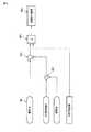
つぎに、本発明の第3の実施形態に係るハイブリッド車両を説明する。なお、第1の実施形態と同様の機能を有する構成は、第1の実施形態と同一の符号を付して説明を省略する。本実施形態では、内燃機関60は、発電機50を駆動するのみに用いられる。このため、ハイブリッド電気自動車10は、内燃機関用伝達機構155を備えていない。また、第2の走行モードが第1の実施形態と異なる。他の構造は、第1の実施形態と同じである。上記異なる点について、具体的に説明する。 Next, a hybrid vehicle according to a third embodiment of the present invention will be described. In addition, the structure which has the same function as 1st Embodiment attaches | subjects the code | symbol same as 1st Embodiment, and abbreviate | omits description. In the present embodiment, the
本実施形態では、ハイブリッド電気自動車10は、上記したように、第1の実施形態の構成に対して、内燃機関用伝達機構155を備えていない。本実施形態では、内燃機関60は、発電機50を駆動するための動力を発生するためだけに用いられる。 In the present embodiment, as described above, the hybrid
このため、本実施形態の第2の走行モードは、内燃機関60によって発電機50を駆動して発電し、発電された電力を、電池80に充電する走行モードである。第2の走行モードは、電動機20と内燃機関60の発生する動力を用いる走行モードである。内燃機関60の発生する動力を用いることは、一例は、第1の実施形態で説明したように、内燃機関用伝達機構130を用いて内燃機関60の出力軸の回転を車輪5に伝達することと、他の例としては、本実施形態で説明したように、内燃機関60によって発電機50を駆動して発電し、発電された電力で電動機20を駆動して走行することである。なお、本実施形態では、発電機50で発電された電力は電池80に充電されたが、電池80を介さすに直接電動機用インバータ40に供給されて電動機20に供給されてもよい。 For this reason, the second traveling mode of the present embodiment is a traveling mode in which the
本実施形態であっても、第1の実施形態と同様の効果が得られる。また、本実施形態であっても、制御部110は、第2の実施形態と同じ動作を行ってもよい。この場合、第2の実施形態と同様の効果が得られる。 Even in the present embodiment, the same effect as in the first embodiment can be obtained. Also in the present embodiment, the
第1〜3の実施形態では、走行システム200は、前記第1の走行モードと前記第2の走行モードとのいずれか一方でハイブリッド電気自動車10を走行可能とする走行手段の一例である。走行手段は、車両を第1,2の走行モードのいずれか一方の走行可能とする機能を有していればよい。そして、第1の走行モードで走行する状態、第2の走行モードで走行する状態を切り替え可能であればよい。 In the first to third embodiments, the traveling
制御部110は、駆動用電池の所定充電率を第1の閾値として、駆動用電池の充電率が第1の閾値以下になると、第1の走行モードから第2の走行モードへの切り替えを行う切り替え手段の一例である。制御部110は、第1〜3の実施形態では、ハイブリッド電気自動車10を統括するメイン制御部である。他の例としては、制御部110とは別に、駆動用電池の劣化度合い値が大きくなるに従って高い充電率を第1の閾値として設定するとともに、劣化度合い値が大きくなるに従って充電率の上昇率を大きくする機能のみを有する専用の制御部が設けられてもよい。 The
アクセル開度検出部140は、アクセル開度検出手段の一例である。CMU82とBMU90とは、駆動用電池の電圧を検出する電圧検出手段の一例を構成している。他の装置を用いて駆動用電池の電圧を検出してもよい。CMU82とBMU90とは、駆動用電池の電流を検出する電流検出手段の一例を構成している。他の装置を用いて駆動用電池の電流を検出してもよい。 The
制御部110は、アクセル開度検出手段により検出したアクセル開度に基づき駆動用電池から電動機へ供給すべき第1の出力値を算出する第1の出力算出手段の一例であるとともに、電圧検出手段により検出した電圧値と電流検出手段により検出した電流値に基づき駆動用電池から電動機へ供給可能な第2の出力値を算出する第2の出力算出手段の一例である。他の例としては、制御部110とは別に、第1の出力算出手段として機能する装置が設けられ、第2の出力算出手段として機能する装置が設けられてもよい。 The
また、CMU82とBMU90とは、駆動用電池の温度検出手段の一例を構成している。他の装置によって駆動用電池の温度を検出するようにしてもよい。 Further, the
また、第1〜3の実施形態では、アクセル開度状態は、小状態、中状態、大状態の3つの状態に分けられている。これは、一例であり、例えば、2つの状態に分けられてもよい、または4つ以上に分けられてもよい。言い換えると、複数のグループに分けられてもよい。 In the first to third embodiments, the accelerator opening state is divided into three states, a small state, a medium state, and a large state. This is an example, and for example, it may be divided into two states, or may be divided into four or more. In other words, it may be divided into a plurality of groups.
また、第1〜3の実施形態では、各アクセル開度状態において、温度範囲は、第1〜5の温度範囲の5つの範囲に分けられている。これは一例である。例えば、より細かく分けられてもよい。 In the first to third embodiments, in each accelerator opening state, the temperature range is divided into five ranges of first to fifth temperature ranges. This is an example. For example, it may be divided more finely.
第1〜3の実施形態では、ハイブリッド電気自動車10は、ハイブリッド車両の一例である。他の例としては、例えば、線路上を走行する電車などの車両に適用されてもよい。 In the first to third embodiments, the hybrid
この発明は、上述した実施の形態そのままに限定されるものではなく、実施段階ではその要旨を逸脱しない範囲で構成要素を変形して具体化できる。また、上述した実施の形態に開示されている複数の構成要素の適宜な組み合わせにより種々の発明を形成できる。例えば、上述した実施の形態に示される全構成要素から幾つかの構成要素を削除しても良い。 The present invention is not limited to the above-described embodiments as they are, and can be embodied by modifying the constituent elements without departing from the scope of the invention in the implementation stage. Various inventions can be formed by appropriately combining a plurality of constituent elements disclosed in the above-described embodiments. For example, you may delete some components from all the components shown by embodiment mentioned above.
10…ハイブリッド電気自動車(ハイブリッド車両)、20…電動機、60…内燃機関、80…電池(駆動用電池)、82…CMU(電圧検出手段、電流検出手段、温度検出手段)、90…BMU(電圧検出手段、電流検出手段、温度検出手段)、110…制御部(切り替え手段、第1の出力値算出手段、第2の出力値算出手段)、120…記憶部、140…アクセル開度検出部(アクセル開度検出手段)、M1…小状態用劣化―充電率マップ(劣化―充電率マップ)、M2…中状態用劣化―充電率マップ(劣化―充電率マップ)、M3…大状態劣化―充電率マップ(劣化―充電率マップ)。 DESCRIPTION OF
Claims (6)
Translated fromJapanese前記駆動用電池の所定充電率を第1の閾値として、前記駆動用電池の充電率が前記第1の閾値以下になると、前記第1の走行モードから第2の走行モードへの切り替えを行う切り替え手段と、
前記駆動用電池の劣化度合い値に応じて第1の閾値を定める劣化―充電率マップを記憶する記憶部と
を備え、
前記劣化―充電率マップは、前記駆動用電池の劣化度合い値が大きくなるに従って高い充電率を前記第1の閾値として設定するとともに、前記劣化度合い値が大きくなるに従って前記第1の閾値の上昇率を大きくするよう設定されている
ことを特徴とするハイブリッド車両。A first traveling mode having an internal combustion engine, a driving battery, and an electric motor driven by electric power from the driving battery, and using only the power generated by the electric motor; the power generated by the electric motor; and the internal combustion A hybrid vehicle that travels in one of the second travel modes using the power generated by the engine,
Switching for switching from the first travel mode to the second travel mode when the predetermined charge rate of the drive battery is a first threshold value and the charge rate of the drive battery is equal to or less than the first threshold value. Means,
A storage unit that stores a deterioration-charge rate map that determines a first threshold value in accordance with a deterioration degree value of the driving battery;
The deterioration-charge rate map sets a high charge rate as the first threshold value as the deterioration degree value of the driving battery increases, and an increase rate of the first threshold value as the deterioration degree value increases. The hybrid vehicle is characterized by being set to be large.
前記駆動用電池の電圧を検出する電圧検出手段と、
前記駆動用電池の電流を検出する電流検出手段と、
前記アクセル開度検出手段により検出したアクセル開度に基づき前記駆動用電池から電動機へ供給すべき第1の出力値を算出する第1の出力算出手段と、
前記電圧検出手段により検出した電圧値と前記電流検出手段により検出した電流値に基づき、前記駆動用電池から前記電動機へ供給可能な第2の出力値を算出する第2の出力算出手段と
を備え、
前記切り替え手段は、前記第1の出力値が前記第2の出力値を上回るときは、前記第1の閾値に対応する充電率よりも高い値の第2の閾値を用いて走行モードの切り替えを行う
ことを特徴とする請求項1に記載のハイブリッド車両。An accelerator opening detecting means for detecting the accelerator opening;
Voltage detecting means for detecting the voltage of the driving battery;
Current detecting means for detecting the current of the driving battery;
First output calculating means for calculating a first output value to be supplied from the driving battery to the electric motor based on the accelerator opening detected by the accelerator opening detecting means;
Second output calculating means for calculating a second output value that can be supplied from the driving battery to the electric motor based on the voltage value detected by the voltage detecting means and the current value detected by the current detecting means. ,
When the first output value exceeds the second output value, the switching means switches the driving mode using a second threshold value that is higher than a charging rate corresponding to the first threshold value. The hybrid vehicle according to claim 1, wherein the hybrid vehicle is performed.
前記複数の劣化―充電率マップの内、一つの劣化−充電率マップを使用している最中に前記第2の閾値を用いた場合は、他のアクセル開度における劣化―充電率マップに移行するまで前記第2閾値を維持し、前記他のアクセル開度における劣化−充電率マップに移行した際に第1、第2閾値のいずれかを使用するかを前記第1、第2の出力で再度判断することを特徴とする請求項2に記載のハイブリッド車両。The storage unit stores a plurality of deterioration-charge rate maps according to the accelerator opening,
If the second threshold is used while one deterioration-charge rate map is being used among the plurality of deterioration-charge rate maps, the process proceeds to a deterioration-charge rate map at another accelerator opening degree. The first and second outputs indicate whether to use the first threshold value or the second threshold value when shifting to the deterioration-charge rate map at the other accelerator opening until the second threshold value is maintained. The hybrid vehicle according to claim 2, wherein the determination is made again.
ことを特徴とする請求項2または3に記載のハイブリッド車両。The switching means prohibits the use of the second threshold and uses the first threshold when the difference between the first output value and the second output value falls below a predetermined value. The hybrid vehicle according to claim 2 or 3.
前記記憶部は前記駆動用電池の温度に応じた劣化―充電率マップを複数記憶し、
前記切り替え手段は、前記駆動用電池の温度に応じた前記劣化―充電率マップの閾値を用いて走行モードの切り替えを行う
ことを特徴とする請求項1〜4のうちのいずれか1項に記載のハイブリッド車両。Having temperature detecting means for the driving battery;
The storage unit stores a plurality of deterioration-charge rate maps according to the temperature of the driving battery,
5. The switching mode according to claim 1, wherein the switching unit performs switching of a driving mode using a threshold value of the deterioration-charge rate map corresponding to a temperature of the driving battery. Hybrid vehicle.
ことを特徴とする請求項5に記載のハイブリッド車両。In the plurality of deterioration-charge rate maps according to the temperature of the driving battery, the first threshold value corresponding to the same deterioration degree value is set higher as the temperature of the driving battery decreases, and the rate of increase is increased. It sets so that it may become large. The hybrid vehicle of Claim 5 characterized by the above-mentioned.
Priority Applications (1)
| Application Number | Priority Date | Filing Date | Title |
|---|---|---|---|
| JP2012014208AJP2013154652A (en) | 2012-01-26 | 2012-01-26 | Hybrid vehicle |
Applications Claiming Priority (1)
| Application Number | Priority Date | Filing Date | Title |
|---|---|---|---|
| JP2012014208AJP2013154652A (en) | 2012-01-26 | 2012-01-26 | Hybrid vehicle |
Publications (1)
| Publication Number | Publication Date |
|---|---|
| JP2013154652Atrue JP2013154652A (en) | 2013-08-15 |
Family
ID=49050309
Family Applications (1)
| Application Number | Title | Priority Date | Filing Date |
|---|---|---|---|
| JP2012014208APendingJP2013154652A (en) | 2012-01-26 | 2012-01-26 | Hybrid vehicle |
Country Status (1)
| Country | Link |
|---|---|
| JP (1) | JP2013154652A (en) |
Cited By (3)
| Publication number | Priority date | Publication date | Assignee | Title |
|---|---|---|---|---|
| JP2018504322A (en)* | 2014-12-22 | 2018-02-15 | ルノー エス.ア.エス. | Method for Energy Management of Rechargeable Hybrid Vehicle Traction Battery |
| JP2019137103A (en)* | 2018-02-06 | 2019-08-22 | トヨタ自動車株式会社 | Electric vehicle |
| CN112566810A (en)* | 2018-08-27 | 2021-03-26 | 松下知识产权经营株式会社 | Vehicle power supply system and vehicle allocation system |
- 2012
- 2012-01-26JPJP2012014208Apatent/JP2013154652A/enactivePending
Cited By (5)
| Publication number | Priority date | Publication date | Assignee | Title |
|---|---|---|---|---|
| JP2018504322A (en)* | 2014-12-22 | 2018-02-15 | ルノー エス.ア.エス. | Method for Energy Management of Rechargeable Hybrid Vehicle Traction Battery |
| EP3237258B1 (en)* | 2014-12-22 | 2023-11-15 | Renault s.a.s | Method for energy management of a rechargeable traction battery of a hybrid vehicle |
| JP2019137103A (en)* | 2018-02-06 | 2019-08-22 | トヨタ自動車株式会社 | Electric vehicle |
| CN112566810A (en)* | 2018-08-27 | 2021-03-26 | 松下知识产权经营株式会社 | Vehicle power supply system and vehicle allocation system |
| CN112566810B (en)* | 2018-08-27 | 2024-05-24 | 松下知识产权经营株式会社 | Vehicle power system and vehicle dispatch system |
Similar Documents
| Publication | Publication Date | Title |
|---|---|---|
| US9233613B2 (en) | Electrically powered vehicle and method for controlling electrically powered vehicle | |
| US10384667B2 (en) | Systems and methods for implementing dynamic operating modes and control policies for hybrid electric vehicles | |
| JP6406215B2 (en) | Vehicle control device | |
| JP6436071B2 (en) | Vehicle control device | |
| JP3560867B2 (en) | Hybrid vehicle battery control device | |
| US6891279B2 (en) | Vehicle control system and control method | |
| JP5608747B2 (en) | Storage capacity management device | |
| JP7020144B2 (en) | Electric vehicle and control method of electric vehicle | |
| JP5741153B2 (en) | Charge control device | |
| WO2013031491A1 (en) | Control device for hybrid vehicle | |
| JP2009248822A (en) | Charging amount controller | |
| JP5552944B2 (en) | Control device for hybrid vehicle | |
| US20100051366A1 (en) | Method for controlling energy in the traction chain of a hybrid vehicle and hybrid vehicle | |
| JP5413606B2 (en) | Control device for hybrid vehicle | |
| JP5024558B2 (en) | Charge control device | |
| JP2013060056A (en) | Control device for hybrid vehicle | |
| JP2013154652A (en) | Hybrid vehicle | |
| JP2006077641A (en) | Control device for hybrid electric automobile | |
| JP7047408B2 (en) | Electric vehicle | |
| JP2017100473A (en) | Motor assist control device of hybrid vehicle | |
| JP5434416B2 (en) | Control device for hybrid vehicle | |
| JP2008163867A (en) | Vehicle control device | |
| JP2006136131A (en) | Vehicle control device | |
| JP5699841B2 (en) | Hybrid car | |
| JP2016043760A (en) | Vehicle control unit |
Legal Events
| Date | Code | Title | Description |
|---|---|---|---|
| RD02 | Notification of acceptance of power of attorney | Free format text:JAPANESE INTERMEDIATE CODE: A7422 Effective date:20130719 |