Movatterモバイル変換


[0]ホーム

URL:


JP2013153816A - Disposable diaper - Google Patents

Disposable diaper
Download PDF

Info

Publication number
JP2013153816A
JP2013153816AJP2012014941AJP2012014941AJP2013153816AJP 2013153816 AJP2013153816 AJP 2013153816AJP 2012014941 AJP2012014941 AJP 2012014941AJP 2012014941 AJP2012014941 AJP 2012014941AJP 2013153816 AJP2013153816 AJP 2013153816A
Authority
JP
Japan
Prior art keywords
fastening
folded
main body
disposable diaper
tape
Prior art date
Legal status (The legal status is an assumption and is not a legal conclusion. Google has not performed a legal analysis and makes no representation as to the accuracy of the status listed.)
Granted
Application number
JP2012014941A
Other languages
Japanese (ja)
Other versions
JP5999906B2 (en
Inventor
Hironobu Yokogawa
廣伸 横川
Current Assignee (The listed assignees may be inaccurate. Google has not performed a legal analysis and makes no representation or warranty as to the accuracy of the list.)
Livedo Corp
Original Assignee
Livedo Corp
Priority date (The priority date is an assumption and is not a legal conclusion. Google has not performed a legal analysis and makes no representation as to the accuracy of the date listed.)
Filing date
Publication date
Application filed by Livedo CorpfiledCriticalLivedo Corp
Priority to JP2012014941ApriorityCriticalpatent/JP5999906B2/en
Publication of JP2013153816ApublicationCriticalpatent/JP2013153816A/en
Application grantedgrantedCritical
Publication of JP5999906B2publicationCriticalpatent/JP5999906B2/en
Activelegal-statusCriticalCurrent
Anticipated expirationlegal-statusCritical

Links

Images

Landscapes

Abstract

Translated fromJapanese

【課題】接続部の共通基部の端部が本体部から離間することを抑制する。
【解決手段】本体部2の後方部の両側部に一対の接続部4が設けられた使い捨ておむつでは、使用前の状態における一対の接続部4のそれぞれが、第1折り返し線451にて折り返された第1折り返し部46と2本の第2折り返し線452にて折り返された2つの第2折り返し部47とを含み、2つの第2折り返し部47の本体長手方向における両側および間において、第1折り返し部46に仮止着用接着剤48が設けられて第1折り返し部46が本体部2に仮止着されている。このように、共通基部42の最外エッジ近傍の部位が本体部2に仮止着されることにより、共通基部42の左右方向の端部が捲れることを抑制することができる。その結果、第1折り返し部46が本体部2から剥離して離間してしまうことを抑制することができる。
【選択図】図5
An end portion of a common base portion of a connection portion is prevented from being separated from a main body portion.
In a disposable diaper in which a pair of connection portions 4 are provided on both sides of a rear portion of a main body portion 2, each of the pair of connection portions 4 in a state before use is folded back at a first folding line 451. The first folded portion 46 and two second folded portions 47 folded by two second folded lines 452, the first folded portion 47 on both sides and in the longitudinal direction of the main body of the two second folded portions 47. An adhesive 48 for temporary fixing is provided on the folded portion 46 so that the first folded portion 46 is temporarily fixed to the main body portion 2. As described above, the portion in the vicinity of the outermost edge of the common base portion 42 is temporarily fixed to the main body portion 2, so that it is possible to prevent the end portion of the common base portion 42 in the left-right direction from curling. As a result, the first folded portion 46 can be prevented from being separated from the main body portion 2 and separated.
[Selection] Figure 5

Description

Translated fromJapanese

本発明は、使い捨ておむつに関する。  The present invention relates to a disposable diaper.

従来より、着用者からの排泄物を受ける使い捨ておむつの一つとして、着用者の腹側に接する部位と背側に接する部位とを止着テープにより腰周りで止着して着用するテープタイプのものが利用されている。テープタイプの使い捨ておむつでは、製造時等に止着テープが意図しない部位に止着してしまうことを防止するために、面ファスナ等の止着部を内側にして止着テープが折り返されて仮止着されていることが多い。  Conventionally, as a disposable diaper that receives excrement from the wearer, it is a type of tape that is worn around the waist with a fastening tape between the part contacting the abdomen and the part contacting the back of the wearer Things are being used. In a tape-type disposable diaper, the fastening tape is folded back with the fastening part such as a hook-and-loop fastener inside to prevent the fastening tape from being attached to an unintended part during production. It is often fastened.

例えば、特許文献1の紙おむつでは、一対のサイドパネルが、紙おむつの左右の後身頃サイドフラップから左右方向に突出しており、各サイドパネルは、不織布からなる基材シートと、前身頃に止着するメカニカルファスナのオス材からなる止着部とを備える。基材シートは、略矩形の固定端部と、固定端部から左右方向に突出する2つの自由端部とを備え、各自由端部上に上記止着部が1つずつ設けられる。  For example, in the paper diaper ofpatent document 1, a pair of side panels protrudes from the left and right rear body side flaps of the paper diaper in the left-right direction, and each side panel is fastened to the base material sheet made of nonwoven fabric and the front body. And a fastening portion made of a male material of a mechanical fastener. The base sheet includes a substantially rectangular fixed end portion and two free end portions protruding in the left-right direction from the fixed end portion, and one fastening portion is provided on each free end portion.

特許文献1の紙おむつの製造工程では、サイドパネルの自由端部が、自由端部と固定端部との境界にて、止着部を内側にして固定端部側へと折り返される。固定端部では、折り返された止着部と重なる部位に接着剤が予め塗布されており、当該接着剤により、止着部が固定端部上に剥離可能に固定される。また、自由端部の止着部の裏側に接着剤が塗布され、後身頃サイドフラップの左右方向のエッジ(すなわち、後身頃サイドフラップとサイドパネルとの境界)近傍において、後身頃サイドフラップに接着剤が塗布される。そして、上記エッジにてサイドパネルが後身頃サイドフラップ上に折り返され、自由端部上の接着剤および後身頃サイドフラップ上の接着剤により、サイドパネルが後身頃サイドフラップ上に剥離可能に固定される。  In the manufacturing process of the paper diaper ofPatent Document 1, the free end portion of the side panel is folded back toward the fixed end portion with the fastening portion inside, at the boundary between the free end portion and the fixed end portion. In the fixed end portion, an adhesive is applied in advance to a portion overlapping with the folded-back fastening portion, and the fastening portion is detachably fixed on the fixed end portion by the adhesive. Adhesive is applied to the back side of the fastening part at the free end, and it adheres to the rear body side flaps in the vicinity of the left and right edges of the rear body side flaps (ie, the boundary between the rear body side flaps and the side panel). The agent is applied. Then, the side panel is folded back on the rear body side flap at the edge, and the side panel is detachably fixed on the rear body side flap by the adhesive on the free end and the adhesive on the rear body side flap. The

また、特許文献2の使い捨ておむつでは、おむつ本体の後身頃の両測縁部にファスニングテープが配置され、各ファスニングテープの先端部に機械的ファスナのフック部材が設けられる。使い捨ておむつの使用前の状態では、ファスニングテープの先端部が、フック部材を内側にしてファスニングテープの中央部と重なるように折り返され、当該中央部に予め塗布された接着剤によりフック部材が仮止めされる。ファスニングテープは、さらに、中央部よりも内側にて折り返され、ファスニングテープのフック部材の裏側、あるいは、ファスニングテープの中央部よりも内側に塗布された接着剤により仮止めされる。  Moreover, in the disposable diaper ofpatent document 2, a fastening tape is arrange | positioned in the both edge measuring part of the back body of a diaper main body, and the hook member of a mechanical fastener is provided in the front-end | tip part of each fastening tape. In the state before using the disposable diaper, the front end of the fastening tape is folded back so as to overlap the central portion of the fastening tape with the hook member inside, and the hook member is temporarily fixed by the adhesive previously applied to the central portion. Is done. The fastening tape is further folded back on the inner side of the central portion, and temporarily fixed by an adhesive applied on the back side of the hook member of the fastening tape or on the inner side of the central portion of the fastening tape.

特開2004−298445号公報JP 2004-298445 A特開2005−296603号公報JP 2005-296603 A

ところで、特許文献1の紙おむつでは、後身頃サイドフラップ上に固定されたサイドパネルにおいて、後身頃サイドフラップのエッジから離れた端部に接着剤が塗布されていないため、紙おむつの製造途上において、サイドパネルの当該端部が捲れてしまい、サイドパネルの後身頃サイドフラップからの意図しない剥離が生じてしまうおそれがある。また、特許文献2の使い捨ておむつにおいても同様に、折り返されたファスニングテープの端部に接着剤が塗布されていないため、ファスニングテープが端部から捲れて意図しない剥離が生じてしまうおそれがある。さらに、特許文献1および特許文献2のおむつでは、メカニカルファスナのオス材の裏側に接着剤が塗布されるが、オス材が設けられる部位は周囲の部位よりも厚くなるため、接着剤を塗布しにくい。  By the way, in the paper diaper ofpatent document 1, in the side panel fixed on the back body side flap, since the adhesive is not applied to the end part away from the edge of the back body side flap, There is a possibility that the end of the panel will be rolled up and unintentional peeling from the side flaps of the rear body of the side panel may occur. Similarly, in the disposable diaper ofPatent Document 2, since the adhesive is not applied to the end portion of the folded fastening tape, the fastening tape may fall from the end portion and unintentional peeling may occur. Furthermore, in the diapers ofPatent Document 1 andPatent Document 2, an adhesive is applied to the back side of the male material of the mechanical fastener. However, since the part where the male material is provided is thicker than the surrounding part, the adhesive is applied. Hateful.

本発明は、上記課題に鑑みなされたものであり、本体部の後方部の両側部に一対の接続部が設けられた使い捨ておむつにおいて、接続部の共通基部の端部が本体部から離間することを抑制することを目的としている。  The present invention has been made in view of the above problems, and in a disposable diaper in which a pair of connection portions are provided on both sides of the rear portion of the main body portion, the end of the common base portion of the connection portion is separated from the main body portion. The purpose is to suppress.

請求項1に記載の発明は、使い捨ておむつであって、前方部、股下部および後方部を第1の方向に順に有する略シート状の本体部と、前記後方部の両側部に取り付けられ、前記前方部の外面に止着されることにより、前記後方部の前記両側部を前記前方部の両側部に接続する一対の接続部とを備え、展開状態における前記一対の接続部のそれぞれが、前記後方部から前記第1の方向に垂直な左右方向である第2の方向へと延びる共通基部と、前記第1の方向に配列されるとともにそれぞれが前記共通基部から前記第2の方向へと延びる2つの止着テープとを備え、前記2つの止着テープのそれぞれが、テープ状のテープ基部と、前記テープ基部の内面に設けられ、前記前方部の前記外面に対して止着可能な止着部とを備え、使用前の状態における前記一対の接続部のそれぞれが、前記共通基部の内面と前記本体部とが対向するように前記共通基部が折り返されることにより前記本体部に対向する第1折返し部と、前記止着部と前記共通基部の前記内面とが対向するように前記2つの止着テープが折り返されることにより前記本体部と前記第1折返し部との間に位置する2つの第2折返し部とを含み、少なくとも、前記2つの第2折返し部の前記第1の方向における両側および間において、前記第1折返し部に仮止着用接着剤が設けられて前記第1折返し部が前記本体部に仮止着されている。  The invention according toclaim 1 is a disposable diaper, which is attached to a substantially sheet-like main body portion having a front portion, a crotch portion and a rear portion in order in a first direction, and both sides of the rear portion, A pair of connecting parts that connect the both side parts of the rear part to both side parts of the front part by being fastened to the outer surface of the front part, and each of the pair of connecting parts in the unfolded state is A common base extending from a rear part in a second direction which is a left-right direction perpendicular to the first direction, and arranged in the first direction and each extending from the common base in the second direction Two fastening tapes, and each of the two fastening tapes is provided on a tape-shaped tape base and an inner surface of the tape base, and can be fastened to the outer surface of the front portion. In the state before use. Each of the pair of connection portions is configured such that the common base portion is folded back so that the inner surface of the common base portion and the main body portion face each other, so that the first folding portion faces the main body portion, and the fastening portion. Including two second folded parts positioned between the main body part and the first folded part by folding the two fastening tapes so that the inner surface of the common base part faces, Between both sides in the first direction of the two second folded portions and between the two, the first folded portion is provided with an adhesive for temporarily fixing, and the first folded portion is temporarily fixed to the main body portion. .

請求項2に記載の発明は、請求項1に記載の使い捨ておむつであって、前記仮止着用接着剤が、前記2つの第2折返し部にも設けられ、使用前の状態において、前記第1折返し部と共に前記2つの第2折返し部も前記本体部に仮止着されている。  Invention ofClaim 2 is the disposable diaper ofClaim 1, Comprising: The said adhesive for temporary fixing is provided also in the said 2nd 2nd folding | turning part, In the state before use, said 1st The two second folded portions as well as the folded portions are temporarily fixed to the main body portion.

請求項3に記載の発明は、請求項2に記載の使い捨ておむつであって、前記仮止着用接着剤が、前記第1折返し部および前記2つの第2折返し部上において前記第1の方向に連続して設けられている。  Invention ofClaim 3 is a disposable diaper ofClaim 2, Comprising: The said adhesive for temporary fixing is a said 1st direction on the said 1st folding | turning part and the said 2nd folding | turning part in the said 1st direction. It is provided continuously.

請求項4に記載の発明は、請求項1に記載の使い捨ておむつであって、使用前の状態において、前記2つの第2折返し部と前記本体部との間に前記仮止着用接着剤が存在しない。  Invention ofClaim 4 is a disposable diaper ofClaim 1, Comprising: In the state before use, the said adhesive for temporary fixing exists between the said 2nd 2nd folding | turning part and the said main-body part. do not do.

請求項5に記載の発明は、請求項1ないし4のいずれかに記載の使い捨ておむつであって、前記共通基部が略矩形状であり、展開状態における前記共通基部の前記本体部から最も離れた最外エッジにおいて、前記最外エッジの前記第1の方向の両端から離れた位置から、前記2つの止着テープが前記第2の方向へと延び、前記最外エッジと前記仮止着用接着剤との間の前記第2の方向における距離が、前記最外エッジの前記両端から最寄りの止着テープの付け根位置までの前記第1の方向における距離よりも小さい。  Invention of Claim 5 is a disposable diaper in any one ofClaim 1 thru | or 4, Comprising: The said common base is a substantially rectangular shape, The furthest away from the said main-body part of the said common base in an unfolded state At the outermost edge, the two fastening tapes extend in the second direction from positions away from both ends of the outermost edge in the first direction, and the outermost edge and the temporary fastening adhesive In the second direction is smaller than the distance in the first direction from the both ends of the outermost edge to the base position of the nearest fastening tape.

請求項6に記載の発明は、請求項1ないし5のいずれかに記載の使い捨ておむつであって、前記一対の接続部の各止着テープが、前記テープ基部の前記内面において前記止着部と前記共通基部との間に設けられて前記前方部の前記外面に対して止着可能なもう1つの止着部をさらに備え、使用前の状態における前記各止着テープが、前記止着部と前記もう1つの止着部との間にて折り返されている。  Invention of Claim 6 is a disposable diaper in any one ofClaim 1 thru | or 5, Comprising: Each fastening tape of a pair of said connection part is the said fastening part in the said inner surface of the said tape base part. And further comprising another fastening portion provided between the common base portion and fastened to the outer surface of the front portion, wherein each fastening tape in a state before use is the fastening portion. It is folded between the other fastening portion.

請求項7に記載の発明は、請求項6に記載の使い捨ておむつであって、使用前の状態において、前記仮止着用接着剤が、前記第2の方向に関して前記各止着テープの前記止着部と前記もう1つの止着部との間に位置する。  Invention of Claim 7 is a disposable diaper of Claim 6, Comprising: In the state before use, the said adhesive for temporary fixing is the said fastening of each said fastening tape regarding the said 2nd direction. And the other fastening portion.

請求項8に記載の発明は、請求項6または7に記載の使い捨ておむつであって、前記各止着テープの前記止着部および前記もう1つの止着部が、前記前方部の前記外面に対して止着可能な微細フック構造を有し、前記第1の方向における前記各止着テープの前記テープ基部の幅が、前記共通基部から離れるに従って漸次減少し、前記もう1つの止着部が、前記第1の方向における前記テープ基部の全幅に亘って設けられる。  Invention of Claim 8 is a disposable diaper of Claim 6 or 7, Comprising: The said fastening part and each said other fastening part of each said fastening tape are on the said outer surface of the said front part. A width of the tape base of each fastening tape in the first direction gradually decreases as the distance from the common base increases, and the other fastening portion , Provided across the entire width of the tape base in the first direction.

請求項9に記載の発明は、請求項1ないし7のいずれかに記載の使い捨ておむつであって、互いに係合する微細フック構造および微細ループ構造のうち一方が前記本体部の前記前方部に設けられ、他方が前記止着部に設けられる。  The invention according to claim 9 is the disposable diaper according to any one ofclaims 1 to 7, wherein one of a fine hook structure and a fine loop structure that are engaged with each other is provided at the front portion of the main body. And the other is provided at the fastening portion.

本発明では、接続部の共通基部の端部が本体部から離間することを抑制することができる。  In this invention, it can suppress that the edge part of the common base of a connection part leaves | separates from a main-body part.

第1の実施の形態に係る使い捨ておむつの平面図である。It is a top view of the disposable diaper which concerns on 1st Embodiment.使い捨ておむつの断面図である。It is sectional drawing of a disposable diaper.使い捨ておむつの斜視図である。It is a perspective view of a disposable diaper.接続部近傍の平面図である。It is a top view of a connection part vicinity.接続部近傍の平面図である。It is a top view of a connection part vicinity.接続部近傍の断面図である。It is sectional drawing of a connection part vicinity.接続部の平面図である。It is a top view of a connection part.第2の実施の形態に係る使い捨ておむつの接続部の平面図である。It is a top view of the connection part of the disposable diaper which concerns on 2nd Embodiment.接続部近傍の平面図である。It is a top view of a connection part vicinity.他の接続部の平面図である。It is a top view of another connection part.

図1は、本発明の第1の実施の形態に係る使い捨ておむつ1を広げた状態にて示す平面図である。使い捨ておむつ1は、着用者の腹側に当接する部位と背側に当接する部位とを、左右両側の接続部4により腰周りで止着して着用するテープタイプの使い捨ておむつであり、着用者からの排泄物を受ける。図1では、着用時に着用者に接する側(すなわち、着用者側)の面を手前にして使い捨ておむつ1を描いている。  FIG. 1 is a plan view showing thedisposable diaper 1 according to the first embodiment of the present invention in an unfolded state. Thedisposable diaper 1 is a tape-type disposable diaper in which a part that abuts on the abdomen side of a wearer and a part that abuts on the back side are fastened around the waist by connectingportions 4 on both left and right sides. Receive excretion from. In FIG. 1, thedisposable diaper 1 is drawn with the surface on the side in contact with the wearer at the time of wearing (that is, the wearer side) facing forward.

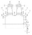
図2は、使い捨ておむつ1を図1中に示すA−Aの位置で長手方向(すなわち、図1中における上下方向)に垂直な面で切断した断面図である。図1および図2に示すように、使い捨ておむつ1は、略シート状の本体部2、および、本体部2の両側部(すなわち、左右方向の両側)上に配置されて本体部2の長手方向のおよそ全長に亘る一対のサイドシート3を備える。ここで、上述の長手方向を第1の方向とすると、左右方向は、第1の方向に垂直、かつ、本体部2の主面に略平行な第2の方向である。  FIG. 2 is a cross-sectional view of thedisposable diaper 1 cut along a plane perpendicular to the longitudinal direction (that is, the vertical direction in FIG. 1) at the position AA shown in FIG. As shown in FIG. 1 and FIG. 2, thedisposable diaper 1 is disposed on a substantially sheet-likemain body 2 and on both sides of the main body 2 (that is, on both sides in the left-right direction). A pair ofside seats 3 is provided over substantially the entire length. Here, when the above-described longitudinal direction is the first direction, the left-right direction is a second direction that is perpendicular to the first direction and substantially parallel to the main surface of themain body 2.

本体部2の図1中における上側の部位201および下側の部位203はそれぞれ、着用者の腹側および背側の肌に接する部位であり、以下の説明では、「前方部201」および「後方部203」と呼ぶ。また、前方部201と後方部203との間において前方部201および後方部203から連続するとともに着用者の股間部に対向する部位202を「股下部202」と呼ぶ。使い捨ておむつ1では、本体部2が前方部201、股下部202および後方部203を長手方向に順に有し、前方部201および後方部203の幅が、股下部202の幅よりも大きい。  Theupper part 201 and thelower part 203 in FIG. 1 of themain body 2 are parts that contact the skin of the wearer's abdomen and dorsal side, respectively. In the following description, “front part 201” and “rear part”Part 203 ". Further, aportion 202 that is continuous from thefront portion 201 and therear portion 203 between thefront portion 201 and therear portion 203 and faces the crotch portion of the wearer is referred to as a “crotch portion 202”. In thedisposable diaper 1, themain body 2 has afront part 201, acrotch part 202, and arear part 203 in order in the longitudinal direction, and the width of thefront part 201 and therear part 203 is larger than the width of thecrotch part 202.

使い捨ておむつ1は、後方部203の両側部に取り付けられた一対の接続部4をさらに備える。使い捨ておむつ1が着用者に装着される際には、本体部2の前方部201および後方部203をそれぞれ着用者の腹側および背側に当接させた状態で、一対の接続部4が、図3に示すように、前方部201の外面(すなわち、着用者に接する面とは反対側の面)の被止着部26に止着されることにより、後方部203の両側部が前方部201の両側部に接続される。  Thedisposable diaper 1 further includes a pair ofconnection parts 4 attached to both sides of therear part 203. When thedisposable diaper 1 is attached to the wearer, the pair ofconnection parts 4 are in a state where thefront part 201 and therear part 203 of themain body part 2 are brought into contact with the abdomen side and the back side of the wearer, respectively. As shown in FIG. 3, both sides of therear portion 203 are moved to the front portion by being fastened to the to-be-attached portion 26 on the outer surface of the front portion 201 (that is, the surface opposite to the surface in contact with the wearer). Connected to both sides of 201.

図1および図2に示すように、本体部2は、透液性のトップシート21、撥水性または不透液性のバックシート23、および、トップシート21とバックシート23との間に配置された吸収コア22を備える。図2では、図示の都合上、使い捨ておむつ1の各構成を厚さ方向に離して描いている。また、図1では、図の理解を容易にするために、吸収コア22の輪郭を太破線にて描いている。図1に示すように、前方部201および後方部203における吸収コア22の幅は、股下部202における吸収コア22の幅よりも大きい。換言すれば、吸収コア22は、いわゆる砂時計型である。  As shown in FIGS. 1 and 2, themain body 2 is disposed between a liquid-permeable top sheet 21, a water-repellent or liquid-impervious back sheet 23, and thetop sheet 21 and theback sheet 23. Anabsorbent core 22 is provided. In FIG. 2, for convenience of illustration, each component of thedisposable diaper 1 is drawn away in the thickness direction. Moreover, in FIG. 1, the outline of theabsorption core 22 is drawn with the thick broken line, in order to make an understanding of a figure easy. As shown in FIG. 1, the width of theabsorbent core 22 in thefront part 201 and therear part 203 is larger than the width of theabsorbent core 22 in thecrotch part 202. In other words, theabsorption core 22 has a so-called hourglass shape.

図3に示す被止着部26は、バックシート23の外面(すなわち、吸収コア22と対向する面とは反対側の面)上に、平面視において吸収コア22(図1および図2参照)と重なるように接合される。被止着部26は、バックシート23上にホットメルト接着剤等により接合される面ファスナのループ部材であり、樹脂等により形成されたベースシート、および、ベースシートのバックシート23に接合される面とは反対側の面に設けられる微細ループ構造を有する。微細ループ構造とは、多数の微細なループ要素の集合を意味する。  3 is an absorbent core 22 (see FIGS. 1 and 2) in plan view on the outer surface of the back sheet 23 (that is, the surface opposite to the surface facing the absorbent core 22). It is joined so as to overlap. The to-be-fixed part 26 is a loop member of a hook-and-loop fastener that is bonded onto theback sheet 23 by a hot melt adhesive or the like, and is bonded to the base sheet formed of resin or the like, and theback sheet 23 of the base sheet. It has a fine loop structure provided on the surface opposite to the surface. The fine loop structure means a set of many fine loop elements.

図2に示すように、トップシート21は、吸収コア22の周りにおいてホットメルト接着剤を介してバックシート23に接合される。また、サイドシート3の左右方向の外側の部位は、バックシート23のトップシート21から露出する部位、および、トップシート21の左右方向のエッジ近傍の部位に、長手方向の全長に亘ってホットメルト接着剤を介して接合される。サイドシート3は、サイドシート本体31、および、サイドシート本体31の左右方向の内縁部である自由端にホットメルト接着剤により接合されて長手方向に伸びる弾性部材32aを備える。  As shown in FIG. 2, thetop sheet 21 is joined to theback sheet 23 via a hot melt adhesive around theabsorbent core 22. Further, the laterally outer portion of theside sheet 3 is hot melted over the entire length in the longitudinal direction at a portion exposed from thetopsheet 21 of thebacksheet 23 and a portion in the vicinity of the lateral edge of thetopsheet 21. Joined via an adhesive. Theside sheet 3 includes a side sheetmain body 31 and anelastic member 32a that is joined to a free end that is an inner edge portion in the left-right direction of the side sheetmain body 31 by a hot melt adhesive and extends in the longitudinal direction.

図1に示す本体部2の長手方向の両端部では、各サイドシート3の左右方向の内側の部位(すなわち、本体部2の左右方向の中心軸側の部位)が、トップシート21の着用者側の面にホットメルト接着剤を介して接合される。また、本体部2の股下部202では、サイドシート3の左右方向の外縁近傍の部位において、長手方向に伸びる2本の弾性部材32bが、サイドシート3とバックシート23とに挟まれてホットメルト接着剤により接合されている。これらのホットメルト接着剤としては、ポリオレフィン系、ゴム系、酢酸ビニル系等のものが利用される。なお、トップシート21とバックシート23との接合やサイドシート3とトップシート21との接合は、熱融着接合や超音波接合等により行われてもよい。  At both ends in the longitudinal direction of themain body 2 shown in FIG. 1, the inner portions in the left-right direction of each side seat 3 (that is, the portion on the central axis side in the left-right direction of the main body 2) are worn by the wearer of thetop sheet 21. Bonded to the side surface via a hot melt adhesive. Further, in thecrotch part 202 of themain body 2, twoelastic members 32 b extending in the longitudinal direction are sandwiched between theside sheet 3 and theback sheet 23 in the vicinity of the outer edge in the left-right direction of theside sheet 3. Bonded with adhesive. As these hot melt adhesives, polyolefin-based, rubber-based, vinyl acetate-based and the like are used. Note that the bonding between thetop sheet 21 and theback sheet 23 and the bonding between theside sheet 3 and thetop sheet 21 may be performed by heat fusion bonding, ultrasonic bonding, or the like.

図1および図2に示す各サイドシート3では、サイドシート本体31の長手方向の両端部の間(すなわち、長手方向の中央部)における内側の部位313が、トップシート21(および他の構成)とは非接合とされており、弾性部材32aが収縮することにより、当該部位313が、図2に示すように、着用者に向かって立ち上がり、着用者の脚の付け根近傍に当接する側壁部(いわゆる、立体ギャザー)となる。また、弾性部材32bが収縮することにより、サイドシート3およびバックシート23が着用者側かつ内側に向かって立ち上がってレッグギャザーが形成され、使い捨ておむつ1の着用時に着用者の足の付け根近傍に密着する。  In eachside seat 3 shown in FIG. 1 and FIG. 2, theinner portion 313 between both ends in the longitudinal direction of the side seat body 31 (that is, the central portion in the longitudinal direction) is the top sheet 21 (and other configurations). As shown in FIG. 2, when theelastic member 32a contracts, theportion 313 rises toward the wearer and comes into contact with the vicinity of the base of the wearer's leg as shown in FIG. So-called three-dimensional gather). Further, when theelastic member 32b contracts, theside sheet 3 and theback sheet 23 rise toward the wearer side and inward to form a leg gather, and when thedisposable diaper 1 is worn, theside sheet 3 and theback sheet 23 are in close contact with the vicinity of the base of the wearer's foot. To do.

図1に示すように、本体部2の長手方向の両端部にはそれぞれ、トップシート21とバックシート23とに挟まれるとともに左右方向に伸びる複数の弾性部材25が設けられる。使い捨ておむつ1では、伸張状態にてトップシート21およびバックシート23に接合された弾性部材25が収縮することによりウエストギャザーが形成され、使い捨ておむつ1の着用時に本体部2が着用者の腰周りに密着する。使い捨ておむつ1では、弾性部材32a,32b、並びに、弾性部材25により本体部2が着用者に密着することにより、脚周りおよび腰周りからの尿等の漏出が防止される。  As shown in FIG. 1, a plurality ofelastic members 25 that are sandwiched between atop sheet 21 and aback sheet 23 and extend in the left-right direction are provided at both ends in the longitudinal direction of themain body 2. In thedisposable diaper 1, a waist gather is formed by theelastic member 25 joined to thetop sheet 21 and theback sheet 23 being contracted in the stretched state, and themain body 2 is placed around the waist of the wearer when thedisposable diaper 1 is worn. In close contact. In thedisposable diaper 1, leakage of urine or the like from around the legs and around the waist is prevented by theelastic members 32 a and 32 b and theelastic member 25 causing themain body 2 to be in close contact with the wearer.

トップシート21は、透液性のシート材料であり、着用者からの排泄物の水分を速やかに捕捉して吸収コア22へと移動させる。トップシート21は、例えば、表面を界面活性剤により親水処理した疎水性繊維(ポリプロピレン、ポリエチレン、ポリエステル、ポリアミド、ナイロン等)にて形成された透液性の不織布であり、当該不織布として、例えば、ポイントボンド不織布やエアスルー不織布、スパンボンド不織布が利用される。なお、トップシート21として、セルロースやレーヨン、コットン等の親水性繊維により形成された不織布(例えば、スパンレース不織布)が利用されてもよい。  Thetop sheet 21 is a liquid-permeable sheet material that quickly captures the moisture of excrement from the wearer and moves it to theabsorbent core 22. Thetop sheet 21 is, for example, a liquid-permeable nonwoven fabric formed of hydrophobic fibers (polypropylene, polyethylene, polyester, polyamide, nylon, etc.) whose surfaces are hydrophilically treated with a surfactant. Point bond nonwoven fabric, air-through nonwoven fabric, and spunbond nonwoven fabric are used. In addition, as thetop sheet 21, a nonwoven fabric (for example, a spunlace nonwoven fabric) formed of hydrophilic fibers such as cellulose, rayon, or cotton may be used.

吸収コア22は、粉砕したパルプ繊維やセルロース繊維等の親水性繊維に粒状の高吸収性ポリマー(SAP(Super Absorbent Polymer))や高吸収性ファイバー等の高吸収性材料を混合したものをティッシュペーパーや透液性不織布等により包み込んで形成され、トップシート21を透過した水分を吸収して迅速に固定する。親水性繊維を包むティッシュペーパーや透液性不織布等は、親水性繊維および吸水性材料とホットメルト接着剤により接合されて、親水性繊維の型崩れ、および、吸水性材料の脱落(特に、吸水後における脱落)を防止する。本実施の形態では、吸収コア22はパルプ繊維およびSAPを含む。  Theabsorbent core 22 is made by mixing a hydrophilic fiber such as pulverized pulp fiber or cellulose fiber with a superabsorbent polymer (SAP (Super Absorbent Polymer)) or a superabsorbent material such as a superabsorbent fiber. It is formed by wrapping with a liquid-permeable nonwoven fabric or the like, and absorbs moisture that has passed through thetop sheet 21 and quickly fixes it. Tissue paper, liquid-permeable nonwoven fabric, etc. that wraps hydrophilic fibers are joined to the hydrophilic fibers and water-absorbing material with a hot-melt adhesive, and the shape of the hydrophilic fibers is lost. Prevent later dropout). In the present embodiment, theabsorbent core 22 includes pulp fibers and SAP.

バックシート23としては、疎水性繊維にて形成された撥水性または不透液性の不織布(例えば、スパンボンド不織布やメルトブロー不織布、SMS(スパンボンド・メルトブロー・スパンボンド)不織布)や、撥水性または不透液性のプラスチックフィルム、あるいは、これらの不織布とプラスチックフィルムとが積層された積層シートが利用され、バックシート23に到達した排泄物の水分等が、本体部2の外側にしみ出すことが防止される。バックシート23にプラスチックフィルムが利用される場合、使い捨ておむつ1のムレを防止して着用者の快適性を向上するという観点からは、透湿性(通気性)を有するプラスチックフィルムが利用されることが好ましい。  As theback sheet 23, a water-repellent or liquid-impervious nonwoven fabric (for example, a spunbond nonwoven fabric, a meltblown nonwoven fabric, an SMS (spunbond / meltblown / spunbond) nonwoven fabric) formed of hydrophobic fibers, A liquid-impermeable plastic film or a laminated sheet obtained by laminating these non-woven fabrics and a plastic film is used, and the water content of excreta reaching theback sheet 23 may ooze out of themain body 2. Is prevented. When a plastic film is used for theback sheet 23, a plastic film having moisture permeability (breathability) may be used from the viewpoint of preventing thedisposable diaper 1 from being stuffy and improving the wearer's comfort. preferable.

サイドシート本体31としては、例えば、疎水性繊維にて形成された撥水性または不透液性の不織布(スパンボンド不織布やメルトブロー不織布、SMS不織布等)が利用される。弾性部材32a,32b,25としては、例えば、ポリウレタン糸、帯状のポリウレタンフィルム、糸状または帯状の天然ゴム等が利用され、本実施の形態では、ポリウレタン糸が各弾性部材として利用される。  As the side sheetmain body 31, for example, a water-repellent or liquid-impervious nonwoven fabric (spunbond nonwoven fabric, melt blown nonwoven fabric, SMS nonwoven fabric, or the like) formed of hydrophobic fibers is used. As theelastic members 32a, 32b, and 25, for example, polyurethane yarn, belt-like polyurethane film, yarn-like or belt-like natural rubber, and the like are used. In the present embodiment, polyurethane yarn is used as each elastic member.

図4は、一対の接続部4のうち一方の接続部4近傍を拡大して示す平面図であり、他方の接続部4の構造も図4に示すものと同様である。一対の接続部4はそれぞれ、本体部2の後方部203から左右方向へと延びる略矩形状の共通基部42と、本体部2の長手方向(すなわち、図1および図4中の上下方向であり、以下、「本体長手方向」ともいう。)に配列されるとともにそれぞれが共通基部42から左右方向へと延びる2つの止着テープ41とを備える。2つの止着テープ41の構造および形状は同様である。図4では、止着テープ41や共通基部42を折り畳まずに展開した展開状態における接続部4を示す。2つの止着テープ41は、展開状態における共通基部42の本体部2から最も離れた最外エッジ421(すなわち、図4中の右側のエッジ)において、最外エッジ421の本体長手方向の両端423から離れた位置から左右方向へと延びる。各止着テープ41の左右方向の長さは、共通基部42の本体部2から露出している部位の左右方向の長さよりも長い。  FIG. 4 is an enlarged plan view showing the vicinity of one connectingportion 4 of the pair of connectingportions 4, and the structure of the other connectingportion 4 is the same as that shown in FIG. Each of the pair ofconnection parts 4 has a substantially rectangularcommon base 42 extending in the left-right direction from therear part 203 of themain body part 2 and the longitudinal direction of the main body part 2 (that is, the vertical direction in FIGS. 1 and 4). , Hereinafter also referred to as “main body longitudinal direction”), and twofastening tapes 41 each extending from thecommon base portion 42 in the left-right direction. The structure and shape of the twofastening tapes 41 are the same. In FIG. 4, theconnection part 4 in the expansion | deployment state which expanded without fixing thefastening tape 41 and thecommon base 42 is shown. The twofastening tapes 41 have bothends 423 in the longitudinal direction of the main body of theoutermost edge 421 at theoutermost edge 421 farthest from themain body 2 of thecommon base 42 in the unfolded state (that is, the right edge in FIG. 4). It extends in the left-right direction from a position away from the center. The length of eachfastening tape 41 in the left-right direction is longer than the length in the left-right direction of the portion exposed from themain body 2 of thecommon base portion 42.

各接続部4では、2つの止着テープ41のそれぞれが、テープ状のテープ基部413、並びに、テープ基部413の一方の主面414(すなわち、図4中における手前側の面)上に設けられる2つの止着部411,412を備える。以下の説明では、共通基部42から遠い側の止着部411を「第1止着部411」といい、もう1つの止着部412を「第2止着部412」という。図4では、図の理解を容易にするために、第1止着部411および第2止着部412に平行斜線を付す。テープ基部413の主面414は、使い捨ておむつ1を着用者に装着する際に本体部2の前方部201(図3参照)に対向する面であり、以下、「内面414」という。  In each connectingportion 4, each of the twofastening tapes 41 is provided on a tape-shapedtape base 413 and onemain surface 414 of the tape base 413 (that is, the front surface in FIG. 4). Twofastening portions 411 and 412 are provided. In the following description, thefastening portion 411 on the side far from thecommon base 42 is referred to as a “first fastening portion 411”, and theother fastening portion 412 is referred to as a “second fastening portion 412”. In FIG. 4, in order to facilitate understanding of the drawing, thefirst fastening part 411 and thesecond fastening part 412 are given a diagonal line. Themain surface 414 of thetape base 413 is a surface that faces the front portion 201 (see FIG. 3) of themain body 2 when thedisposable diaper 1 is attached to the wearer, and is hereinafter referred to as an “inner surface 414”.

第1止着部411は、テープ基部413の先端部418に設けられ、第2止着部412は、テープ基部413の内面414において第1止着部411と共通基部42との間に、第1止着部411と離間して設けられる。各テープ基部413の内面414では、第1止着部411および第2止着部412が、テープ基部413を本体長手方向に横断するように設けられる。換言すれば、第1止着部411および第2止着部412は、テープ基部413の幅方向(すなわち、本体長手方向に一致する方向)においてテープ基部413の全幅に亘って設けられる。  Thefirst fastening portion 411 is provided at thetip portion 418 of thetape base 413, and thesecond fastening portion 412 is disposed between thefirst fastening portion 411 and thecommon base 42 on theinner surface 414 of thetape base 413. 1 is provided apart from thefastening portion 411. On theinner surface 414 of eachtape base 413, afirst fastening portion 411 and asecond fastening portion 412 are provided so as to cross thetape base 413 in the longitudinal direction of the main body. In other words, thefirst fastening portion 411 and thesecond fastening portion 412 are provided over the entire width of thetape base 413 in the width direction of the tape base 413 (that is, the direction matching the longitudinal direction of the main body).

第1止着部411および第2止着部412はそれぞれ、本体部2の前方部201の外面に設けられた被止着部26(図3参照)に対して止着可能な面ファスナのフック部材であり、テープ基部413の内面414上にホットメルト接着剤等により接合される。第1止着部411および第2止着部412はそれぞれ、樹脂等により形成されたベースシート、および、ベースシートのテープ基部413に接合される面とは反対側の面に設けられる微細フック構造を有する。第1止着部411および第2止着部412にそれぞれ設けられた微細フック構造は、多数の微細なフック要素の集合であり、被止着部26の微細ループ構造と互いに係合する(すなわち、被止着部26に対して止着可能である。)。  Thefirst fastening part 411 and thesecond fastening part 412 are hooks of a hook-and-loop fastener that can be fastened to the fastened part 26 (see FIG. 3) provided on the outer surface of thefront part 201 of themain body part 2. It is a member and is joined onto theinner surface 414 of thetape base 413 by a hot melt adhesive or the like. Thefirst fastening portion 411 and thesecond fastening portion 412 are each a base sheet formed of resin or the like, and a fine hook structure provided on a surface of the base sheet opposite to the surface joined to thetape base 413 Have The fine hook structures respectively provided in thefirst fastening part 411 and thesecond fastening part 412 are a collection of a large number of fine hook elements and engage with each other with the fine loop structure of the fastened part 26 (that is, And can be fixed to the fixed portion 26).

各接続部4では、2つの止着テープ41の2つのテープ基部413、および、共通基部42は樹脂や不織布等により形成された1つの接続部シート40の一部であり、2つのテープ基部413はそれぞれ、共通基部42から左右方向の外側(すなわち、本体部2とは反対側)に向かって突出する。また、共通基部42の内端部(接続部シート40の内端部でもある。)は、本体部2のサイドシート3とバックシート23との間に挟まれて接合される。  In eachconnection portion 4, the twotape base portions 413 of the twofastening tapes 41 and thecommon base portion 42 are a part of oneconnection portion sheet 40 formed of resin, nonwoven fabric, or the like, and the twotape base portions 413. Respectively protrude from thecommon base 42 toward the outside in the left-right direction (that is, the side opposite to the main body 2). Further, the inner end portion of the common base portion 42 (which is also the inner end portion of the connection portion sheet 40) is sandwiched and joined between theside sheet 3 and theback sheet 23 of themain body portion 2.

換言すれば、2つのテープ基部413は、本体部2側にて連続する1つの接続部シート40の一部であり、接続部シート40における2つのテープ基部413の接続部分である共通基部42は、本体部2の側方エッジ27から側方へとはみ出している。なお、トップシート21(図2参照)の外縁がバックシート23の外縁に比較的近い位置に位置している場合には、共通基部42の内端部は、トップシート21とバックシート23との間に接合されてもよい。  In other words, the twotape base parts 413 are a part of one connectingpart sheet 40 continuous on themain body part 2 side, and thecommon base part 42 that is a connecting part of the twotape base parts 413 in the connectingpart sheet 40 is Themain body 2 protrudes laterally from theside edge 27. When the outer edge of the top sheet 21 (see FIG. 2) is located at a position relatively close to the outer edge of theback sheet 23, the inner end portion of thecommon base portion 42 is between thetop sheet 21 and theback sheet 23. It may be joined in between.

各止着テープ41では、テープ基部413の幅(すなわち、図4中の上下方向である本体長手方向におけるテープ基部413の幅)が、共通基部42から離れてテープ基部413の先端部418に向かうに従って漸次減少する。第2止着部412の第1止着部411側のエッジ4121(以下、「外エッジ4121」という。)と本体部2の側方エッジ27との間の左右方向の距離は、外エッジ4121とテープ基部413の先端との間の左右方向の距離よりも大きい。また、第2止着部412の共通基部42側のエッジ4122(以下、「内エッジ4122」という。)と本体部2の側方エッジ27との間の左右方向の距離は、内エッジ4122とテープ基部413の先端との間の左右方向の距離よりも小さい。  In eachfastening tape 41, the width of the tape base portion 413 (that is, the width of thetape base portion 413 in the longitudinal direction of the main body, which is the vertical direction in FIG. 4) is separated from thecommon base portion 42 toward thefront end portion 418 of thetape base portion 413. It gradually decreases as The distance in the left-right direction between theedge 4121 on thefirst fastening part 411 side of the second fastening part 412 (hereinafter referred to as “outer edge 4121”) and theside edge 27 of themain body part 2 is theouter edge 4121. Greater than the distance in the left-right direction between the tape and the tip of thetape base 413. Further, the distance in the left-right direction between theedge 4122 on thecommon base 42 side of the second fastening portion 412 (hereinafter referred to as “inner edge 4122”) and theside edge 27 of themain body portion 2 is the same as theinner edge 4122. The distance between the front end of thetape base 413 and the horizontal direction is smaller.

使用前の状態における使い捨ておむつ1では、図5に示すように、一対の接続部4が左右方向の内側(すなわち、本体部2側)に折り返されて本体部2に仮止着されている。図5は、使用前の状態における使い捨ておむつ1の一方の接続部4近傍を拡大して示す平面図であり、他方の接続部4も図5と同様に折り返されて本体部2に仮止着されている。図6は、接続部4近傍の部位を図5中のB−Bの位置にて切断した断面図である。なお、仮止着とは、2つの部位を、剥離可能な状態で互いに止着することであり、剥離する際には、当該2つの部位は、破損することなく容易に剥離される。  In thedisposable diaper 1 in a state before use, as shown in FIG. 5, the pair ofconnection portions 4 are folded back to the inner side in the left-right direction (that is, themain body portion 2 side) and temporarily fixed to themain body portion 2. FIG. 5 is an enlarged plan view showing the vicinity of oneconnection part 4 of thedisposable diaper 1 in a state before use, and theother connection part 4 is also folded back similarly to FIG. Has been. FIG. 6 is a cross-sectional view of a portion in the vicinity of the connectingportion 4 cut at a position BB in FIG. In addition, temporary fixing is to fix two parts to each other in a peelable state, and when peeling, the two parts are easily peeled without being damaged.

図5および図6に示すように、接続部4は、本体長手方向に延びる第1折り返し線451および2本の第2折り返し線452にて折り返される。第1折り返し線451は、共通基部42上において本体部2の側方エッジ27近傍に位置する。2本の第2折り返し線452は、2つの止着テープ41の第1止着部411と第2止着部412との間のテープ基部413上において、第2止着部412の外エッジ4121近傍に位置する。本実施の形態では、第1折り返し線451は、本体部2の側方エッジ27とおよそ重なり、第2折り返し線452は、第2止着部412の外エッジ4121とおよそ重なる。  As shown in FIG. 5 and FIG. 6, the connectingportion 4 is folded at afirst folding line 451 and twosecond folding lines 452 extending in the longitudinal direction of the main body. Thefirst folding line 451 is located in the vicinity of theside edge 27 of themain body 2 on thecommon base 42. The twosecond folding lines 452 are arranged on thetape base 413 between thefirst fastening part 411 and thesecond fastening part 412 of the twofastening tapes 41, and theouter edge 4121 of thesecond fastening part 412. Located in the vicinity. In the present embodiment, thefirst fold line 451 approximately overlaps theside edge 27 of themain body 2, and thesecond fold line 452 approximately overlaps theouter edge 4121 of thesecond fastening part 412.

以下の説明では、接続部4の第1折り返し線451と第2折り返し線452との間の部位を「第1折り返し部46」といい、2本の第2折り返し線452よりも先端部418側の2つの部位をそれぞれ「第2折り返し部47」という。第1折り返し部46および2つの第2折り返し部47は、使用前の状態における一対の接続部4のそれぞれに含まれる。第1折り返し部46は、共通基部42の内面422と本体部2の着用者側の面とが対向するように共通基部42が第1折り返し線451にて折り返されることにより形成される。2つの第2折り返し部47は、それぞれの第1止着部411と共通基部42の内面422とが対向するように2つの止着テープ41が2本の第2折り返し線452にて折り返されることにより形成される。第1折り返し部46は本体部2に対向し、2つの第2折り返し部47は本体部2と第1折り返し部46との間に位置する。各第2折り返し部47の左右方向の長さは、第1折り返し部46の左右方向の長さよりも短い。  In the following description, a portion between thefirst fold line 451 and thesecond fold line 452 of theconnection portion 4 is referred to as a “first fold portion 46”, and thetip 418 side from the two second fold lines 452. These two parts are referred to as “second folding part 47”, respectively. The first foldedportion 46 and the two second foldedportions 47 are included in each of the pair ofconnection portions 4 in a state before use. The first foldedportion 46 is formed by folding thecommon base portion 42 along a first foldedline 451 so that theinner surface 422 of thecommon base portion 42 and the wearer side surface of themain body portion 2 face each other. In the two second foldedportions 47, the twofastening tapes 41 are folded at the two second foldedlines 452 so that thefirst fastening portions 411 and theinner surface 422 of thecommon base portion 42 face each other. It is formed by. The first foldedportion 46 faces themain body 2, and the two second foldedportions 47 are located between themain body 2 and the first foldedportion 46. The length of each second foldedportion 47 in the left-right direction is shorter than the length of the first foldedportion 46 in the left-right direction.

図7は、第1折り返し部46を左右方向に展開した状態、すなわち、接続部4の2つの止着テープ41を2本の第2折り返し線452のみにて折り返した状態を示す一方の接続部4の平面図である。使い捨ておむつ1の製造工程では、図7に示す状態の接続部4に仮止着用接着剤48が塗布される。図7では、図の理解を容易にするために、仮止着用接着剤48に平行斜線を付す(図5においても同様)。なお、他方の接続部4においても、図7と同様の位置に仮止着用接着剤48が塗布される。  FIG. 7 shows one connecting portion showing a state in which the first foldedportion 46 is expanded in the left-right direction, that is, a state in which the twofastening tapes 41 of the connectingportion 4 are folded only by the two second folding lines 452. 4 is a plan view of FIG. In the manufacturing process of thedisposable diaper 1, the adhesive 48 for temporary fixing is apply | coated to theconnection part 4 of the state shown in FIG. In FIG. 7, in order to facilitate understanding of the drawing, a parallel oblique line is given to the temporary fixing adhesive 48 (the same applies to FIG. 5). In addition, also in theother connection part 4, the adhesive 48 for temporary fixing is apply | coated to the same position as FIG.

仮止着用接着剤48は、共通基部42の最外エッジ421近傍において本体長手方向に平行な帯状にコータ等により塗布される。仮止着用接着剤48は、第1折り返し部46および2つの第2折り返し部47上において、本体長手方向に連続して設けられている。換言すれば、接続部4では、第1折り返し部46の本体長手方向の全長に亘って、仮止着用接着剤48が第1折り返し部46および2つの第2折り返し部47上に設けられる。  Thetemporary fixing adhesive 48 is applied by a coater or the like in a strip shape parallel to the longitudinal direction of the main body in the vicinity of theoutermost edge 421 of thecommon base 42. The temporarily wearingadhesive 48 is continuously provided in the longitudinal direction of the main body on the first foldedportion 46 and the two second foldedportions 47. In other words, in theconnection part 4, the temporary wearing adhesive 48 is provided on the first foldedpart 46 and the two second foldedparts 47 over the entire length of the first foldedpart 46 in the longitudinal direction of the main body.

仮止着用接着剤48の本体長手方向の両端部は、共通基部42の最外エッジ421近傍の角部に位置する。仮止着用接着剤48と共通基部42の最外エッジ421との間の左右方向の距離L1(すなわち、仮止着用接着剤48と最外エッジ421との間の仮止着用接着剤が設けられていない領域の幅)は、最外エッジ421の両端423から最寄りの止着テープ41の付け根位置までの本体長手方向における距離L2よりも小さい。  Both ends in the longitudinal direction of the main body of the adhesive 48 for temporary fixing are located at corners in the vicinity of theoutermost edge 421 of thecommon base 42. A distance L1 in the left-right direction between the temporary wearing adhesive 48 and theoutermost edge 421 of the common base portion 42 (that is, the temporary wearing adhesive between the temporary wearing adhesive 48 and theoutermost edge 421 is provided). The width of the non-overlapping region is smaller than the distance L2 in the longitudinal direction of the main body from both ends 423 of theoutermost edge 421 to the nearest root position of thefastening tape 41.

仮止着用接着剤48は、2つの第2折り返し部47の間において第1折り返し部46の内面422に設けられており、また、2つの第2折り返し部47の本体長手方向における両側(すなわち、図7中の上側の第2折り返し部47の上側、および、図7中の下側の第2折り返し部47の下側)において、第1折り返し部46の内面422に設けられている。仮止着用接着剤48は、2つの第2折り返し部47の外面415(すなわち、テープ基部413の内面414とは反対側の主面)にも設けられている。仮止着用接着剤48は、左右方向に関して、各止着テープ41の第1止着部411と第2止着部412との間に位置する。  Thetemporary fixing adhesive 48 is provided on theinner surface 422 of the first foldedportion 46 between the two second foldedportions 47, and both sides of the two second foldedportions 47 in the longitudinal direction of the main body (that is, 7 is provided on theinner surface 422 of the first foldedportion 46 on the upper side of the second foldedportion 47 on the upper side in FIG. 7 and on the lower side of the second foldedportion 47 on the lower side in FIG. Thetemporary fixing adhesive 48 is also provided on theouter surfaces 415 of the two second folded portions 47 (that is, the main surface opposite to theinner surface 414 of the tape base 413). Thetemporary fastening adhesive 48 is located between thefirst fastening part 411 and thesecond fastening part 412 of eachfastening tape 41 in the left-right direction.

仮止着用接着剤48としては、例えば、ホットメルト接着剤が利用される。仮止着用接着剤48は、例えば、スチレン系、オレフィン系、塩化ビニル系等の熱可塑性エラストマーを主剤として含む。本実施の形態では、スチレン・ブタジエン系熱可塑性エラストマーに粘着付与剤および可塑剤を添加した接着剤が、仮止着用接着剤48として利用される。  As thetemporary fixing adhesive 48, for example, a hot melt adhesive is used. The adhesive 48 for temporary fixing includes, for example, a thermoplastic elastomer such as styrene, olefin, or vinyl chloride as a main agent. In the present embodiment, an adhesive obtained by adding a tackifier and a plasticizer to a styrene / butadiene-based thermoplastic elastomer is used as the adhesive 48 for temporary fixing.

使用前の状態における使い捨ておむつ1では、図5および図6に示すように、仮止着用接着剤48により、第1折り返し部46が本体部2に仮止着されており、2つの第2折り返し部47も第1折り返し部46と共に本体部2に仮止着されている。そして、使い捨ておむつ1が使用される際には、接続部4が本体部2から離れるように引っ張られることにより、仮止着用接着剤48による仮止着が解除され、接続部4が図4に示す展開状態とされる。  In thedisposable diaper 1 in a state before use, as shown in FIGS. 5 and 6, the first foldedportion 46 is temporarily fastened to themain body portion 2 by the temporarily fasteningadhesive 48, and the two second folded backs are provided. Theportion 47 is also temporarily fixed to themain body portion 2 together with the first foldedportion 46. Then, when thedisposable diaper 1 is used, theconnection part 4 is pulled away from themain body part 2 to release the temporary attachment by the temporary attachment adhesive 48, and theconnection part 4 is shown in FIG. The expanded state is shown.

以上に説明したように、使い捨ておむつ1では、使用前の状態における一対の接続部4のそれぞれが、第1折り返し部46と2つの第2折り返し部47とを含み、2つの第2折り返し部47の本体長手方向における両側および間において、第1折り返し部46に仮止着用接着剤48が設けられて第1折り返し部46が本体部2に仮止着されている。このように、共通基部42の最外エッジ421近傍の部位が本体部2に仮止着されることにより、共通基部42の左右方向の端部が捲れることを抑制することができる。その結果、第1折り返し部46が本体部2から剥離して離間してしまうことを抑制することができる。  As described above, in thedisposable diaper 1, each of the pair ofconnection parts 4 in the state before use includes the first foldedpart 46 and the two second foldedparts 47, and the two second foldedparts 47. Are attached to the first foldedportion 46 and the first foldedportion 46 is temporarily fixed to themain body portion 2. As described above, when the portion of thecommon base portion 42 near theoutermost edge 421 is temporarily fixed to themain body portion 2, it is possible to prevent the end portion of thecommon base portion 42 in the left-right direction from being curled. As a result, the first foldedportion 46 can be prevented from being separated from themain body portion 2 and separated.

また、2つの第2折り返し部47にも仮止着用接着剤48が設けられ、第2折り返し部47も本体部2に仮止着されることにより、接続部4の本体部2に対する仮止着の強度を増大することができる。その結果、第1折り返し部46および第2折り返し部47が本体部2から剥離して離間してしまうことをより抑制することができる。さらに、仮止着用接着剤48が、第1折り返し部46および2つの第2折り返し部47上において本体長手方向に連続して設けられることにより、共通基部42の端部のうち特に捲れやすい最外エッジ421の両端423近傍の部位(すなわち、共通基部42の角部)が捲れることを抑制することができる。その結果、第1折り返し部46および第2折り返し部47が本体部2から剥離して離間してしまうことをより一層抑制することができる。また、仮止着用接着剤48が本体長手方向に連続しているため、コータ等により仮止着用接着剤48を容易に塗布することができる。  In addition, the two second foldedportions 47 are also provided with an adhesive 48 for temporary fixing, and the second foldedportion 47 is also temporarily fixed to themain body portion 2, thereby temporarily fixing theconnection portion 4 to themain body portion 2. The strength of the can be increased. As a result, it is possible to further suppress the first foldedportion 46 and the second foldedportion 47 from being separated from themain body portion 2 and separated. Further, thetemporary fastening adhesive 48 is continuously provided in the longitudinal direction of the main body on the first foldedportion 46 and the two second foldedportions 47, so that the outermost end of thecommon base portion 42 is particularly liable to be rolled. It can suppress that the site | part (namely, corner | angular part of the common base 42) near the both ends 423 of theedge 421 is curled. As a result, it is possible to further suppress the first foldedportion 46 and the second foldedportion 47 from being separated from themain body portion 2 and separated. Further, since thetemporary fixing adhesive 48 is continuous in the longitudinal direction of the main body, the temporary fixing adhesive 48 can be easily applied by a coater or the like.

上述のように、接続部4では、共通基部42の最外エッジ421と仮止着用接着剤48との間の距離L1が、最外エッジ421の両端423から最寄りの止着テープ41の付け根位置までの距離L2よりも小さい。このように、仮止着用接着剤48が、共通基部42の両端423近傍の部位にも設けられることにより、共通基部42の角部が捲れることをより一層抑制することができる。その結果、第1折り返し部46および第2折り返し部47が本体部2から剥離して離間してしまうことをさらに抑制することができる。  As described above, in theconnection portion 4, the distance L1 between theoutermost edge 421 of thecommon base 42 and the adhesive 48 for temporary fixing is the base position of thenearest fastening tape 41 from both ends 423 of theoutermost edge 421. Is smaller than the distance L2. As described above, thetemporary fastening adhesive 48 is also provided in the vicinity of the both ends 423 of thecommon base portion 42, so that the corner portion of thecommon base portion 42 can be further prevented from being bent. As a result, it is possible to further suppress the first foldedportion 46 and the second foldedportion 47 from being separated from themain body portion 2 and separated.

接続部4では、各止着テープ41に左右方向に離間する第1止着部411および第2止着部412が設けられる。止着テープ41において、第1止着部411および第2止着部412が設けられた部位は、止着部が設けられていない部位に比べて比較的剛性が高く、かつ、比較的厚い。接続部4では、使用前の状態における各止着テープ41が、第1止着部411と第2止着部412との間の比較的剛性が低い部位にて折り返されることにより、止着テープ41を容易に折り返して第2折り返し部47を容易に形成することができる。  In theconnection part 4, eachfastening tape 41 is provided with afirst fastening part 411 and asecond fastening part 412 that are separated in the left-right direction. In thefastening tape 41, the portion where thefirst fastening portion 411 and thesecond fastening portion 412 are provided is relatively rigid and relatively thick compared to the portion where the fastening portion is not provided. In theconnection part 4, eachfastening tape 41 in a state before use is folded back at a portion having a relatively low rigidity between thefirst fastening part 411 and thesecond fastening part 412. 41 can be easily folded and the second foldedportion 47 can be easily formed.

また、仮止着用接着剤48が、第1止着部411と第2止着部412との間の比較的薄い部位に位置するため、コータ等により仮止着用接着剤48を容易に塗布することができる。さらに、第1折り返し部46および第2折り返し部47において仮止着用接着剤48が設けられる部位の剛性が比較的低く、本体部2の仮止着用接着剤48と接触する部位の剛性も比較的低いため、両部位のうち一方の部位が捩れた場合、他方の部位が容易に変形して捩れに追従する。その結果、仮止着用接着剤48による仮止着の意図しない剥離を抑制し、第1折り返し部46および第2折り返し部47が本体部2から離間してしまうことをさらに抑制することができる。  Further, since thetemporary fixing adhesive 48 is located at a relatively thin portion between thefirst fixing portion 411 and thesecond fixing portion 412, thetemporary fixing adhesive 48 is easily applied by a coater or the like. be able to. Furthermore, the rigidity of the part where the temporary wearing adhesive 48 is provided in the first foldedpart 46 and the second foldedpart 47 is relatively low, and the rigidity of the part contacting the temporary wearingadhesive 48 of themain body part 2 is also relatively high. Therefore, when one of the two parts is twisted, the other part easily deforms to follow the twist. As a result, it is possible to suppress unintended peeling of the temporary fastening by the temporary wearing adhesive 48 and further suppress the first foldedportion 46 and the second foldedportion 47 from being separated from themain body portion 2.

上述のように、2つの止着テープ41はそれぞれ、第2止着部412の外エッジ4121近傍にて折り返される。このため、図5に示す使用前の状態の使い捨ておむつ1において、第1折り返し部46の左右方向の内側の端部(すなわち、本体部2の側方エッジ27から左右方向に最も離れた部位)に第2止着部412が位置する。これにより、比較的剛性が高い第2止着部412を把持して、仮止着用接着剤48による仮止着を容易に解除することができる。また、テープ基部413が例えば不織布により形成されている場合、折り返された第2折り返し部47が第2止着部412により仮止着されるため、第1折り返し部46と第2折り返し部47とをまとめて容易に取り扱うことができる。  As described above, the twofastening tapes 41 are folded back in the vicinity of theouter edge 4121 of thesecond fastening portion 412. For this reason, in thedisposable diaper 1 in the state before use shown in FIG. 5, the inner end portion in the left-right direction of the first folded portion 46 (that is, the portion farthest from theside edge 27 of themain body portion 2 in the left-right direction). Thesecond fastening portion 412 is located at the top. Thereby, thesecond fastening part 412 having relatively high rigidity can be gripped, and the temporary fastening by the temporary fastening adhesive 48 can be easily released. Further, when thetape base 413 is made of, for example, a nonwoven fabric, the folded second foldedportion 47 is temporarily fixed by the second fixedportion 412, and therefore the first foldedportion 46 and the second foldedportion 47 Can be easily handled together.

さらに、各止着テープ41では、テープ基部413の幅が、共通基部42から離れてテープ基部413の先端部418に向かうに従って漸次減少する。このため、第2折り返し部47の本体長手方向の両側に第2止着部412の一部がはみ出る。そして、第2折り返し部47の両側に露出する第2止着部412の一部が本体部2に仮止着されることにより、第1折り返し部46および第2折り返し部47が本体部2から剥離して離間してしまうことをより一層抑制することができる。  Further, in eachfastening tape 41, the width of thetape base 413 gradually decreases as it moves away from thecommon base 42 and toward thetip 418 of thetape base 413. For this reason, a part of2nd fastening part 412 protrudes in the both sides of the main body longitudinal direction of the 2nd folding | returningpart 47. FIG. Then, a part of thesecond fastening part 412 exposed on both sides of the second foldedpart 47 is temporarily secured to themain body part 2, whereby the first foldedpart 46 and the second foldedpart 47 are removed from themain body part 2. It is possible to further suppress the separation and separation.

次に、本発明の第2の実施の形態に係る使い捨ておむつについて説明する。図8は、第2の実施の形態に係る使い捨ておむつの一方の接続部4aを拡大して示す平面図である。図8では、図7と同様に、第1折り返し部46を左右方向に展開した状態、すなわち、接続部4aの2つの止着テープ41を2本の第2折り返し線452のみにて折り返した状態を示す図である。接続部4aでは、2つの第2折り返し部47の本体長手方向の両側および間に仮止着用接着剤48が設けられ、2つの第2折り返し部47上には仮止着用接着剤は設けられない。その他の構成は、図1ないし図7に示す使い捨ておむつ1と同様であり、以下の説明では、対応する構成に同符号を付す。  Next, the disposable diaper which concerns on the 2nd Embodiment of this invention is demonstrated. FIG. 8 is an enlarged plan view showing oneconnection portion 4a of the disposable diaper according to the second embodiment. In FIG. 8, as in FIG. 7, the first foldedportion 46 is unfolded in the left-right direction, that is, the twofastening tapes 41 of the connectingportion 4a are folded only by the two second foldedlines 452. FIG. In theconnection portion 4 a, thetemporary fixing adhesive 48 is provided between both sides of the two second foldedportions 47 in the longitudinal direction of the main body, and no temporary fixing adhesive is provided on the two second foldedportions 47. . Other configurations are the same as those of thedisposable diaper 1 shown in FIGS. 1 to 7, and in the following description, the same reference numerals are given to the corresponding configurations.

接続部4aでは、第2折り返し部47が第1折り返し部46上に折り返された状態で、仮止着用接着剤48が本体長手方向に間欠的に塗布されることにより、仮止着用接着剤48が第1折り返し部46上のみに設けられる。仮止着用接着剤48は、第2折り返し部47上(すなわち、第2折り返し部47の第1折り返し部46とは反対側)、および、第1折り返し部46と第2折り返し部47との間には設けられない。接続部4aでは、また、第2折り返し部47が第1折り返し部46上に折り返されるよりも前に、第1折り返し部46の本体長手方向の全長に亘って仮止着用接着剤48が塗布され、その後、第2折り返し部47が折り返されてもよい。これにより、仮止着用接着剤48は、第1折り返し部46上に設けられ、第2折り返し部47上には設けられない。この場合、第2折り返し部47は、第1折り返し部46と第2折り返し部47との間の図示省略の仮止着用接着剤48により、第1折り返し部46上に仮止着される。  In theconnection portion 4a, the temporary wearing adhesive 48 is intermittently applied in the longitudinal direction of the main body in a state in which the second foldedportion 47 is folded on the first foldedportion 46, whereby the temporary wearing adhesive 48 is provided. Is provided only on the first foldedportion 46. The temporarily wearingadhesive 48 is on the second folded portion 47 (that is, on the side opposite to the first foldedportion 46 of the second folded portion 47) and between the first foldedportion 46 and the second foldedportion 47. Is not provided. In the connectingportion 4a, the temporary wearing adhesive 48 is applied over the entire length of the first foldedportion 46 in the longitudinal direction of the main body before the second foldedportion 47 is folded on the first foldedportion 46. Thereafter, the second foldedportion 47 may be folded. Accordingly, thetemporary fixing adhesive 48 is provided on the first foldedportion 46 and is not provided on the second foldedportion 47. In this case, the second foldedportion 47 is temporarily fixed onto the first foldedportion 46 by a temporary fastening adhesive 48 (not shown) between the first foldedportion 46 and the second foldedportion 47.

図9は、図5と同様に、使用前の状態(すなわち、接続部4aが第1折り返し線451および2本の第2折り返し線452にて折り返された状態)における接続部4a近傍を拡大して示す平面図である。図9に示すように、第1折り返し部46上において、仮止着用接着剤48は、第1の実施の形態と同様の位置に設けられる。このように、少なくとも、2つの第2折り返し部47の本体長手方向の両側および間に仮止着用接着剤48が設けられることにより、第1の実施の形態と同様に、共通基部42の左右方向の端部が捲れることを抑制し、第1折り返し部46が本体部2から剥離して離間してしまうことを抑制することができる。  FIG. 9 is an enlarged view of the vicinity of theconnection portion 4a in a state before use (that is, a state in which theconnection portion 4a is folded at thefirst folding line 451 and the two second folding lines 452), as in FIG. FIG. As shown in FIG. 9, on the first foldedportion 46, thetemporary fixing adhesive 48 is provided at the same position as in the first embodiment. As described above, by providing the temporary fixing adhesive 48 at least between both sides in the longitudinal direction of the main body of the two second foldedportions 47, the left and right direction of thecommon base 42 is the same as in the first embodiment. It is possible to suppress the end portion of themain body 2 from curling and to prevent the first foldedportion 46 from being separated from themain body portion 2.

また、使用前の状態において、2つの第2折り返し部47と本体部2との間には仮止着用接着剤は存在しない。これにより、使い捨ておむつ1を着用者に装着した際に、接続部4aの外面(すなわち、本体部2に対向する主面とは反対側の主面)に仮止着用接着剤が存在せず、接続部4aの外面が着衣に付着してしまうことを防止することができる。  In addition, there is no temporary fixing adhesive between the two second foldedportions 47 and themain body 2 in a state before use. Thereby, when thedisposable diaper 1 is attached to the wearer, there is no temporary wearing adhesive on the outer surface of theconnection portion 4a (that is, the main surface opposite to the main surface facing the main body portion 2), It can prevent that the outer surface of theconnection part 4a adheres to clothing.

以上、本発明の実施の形態について説明してきたが、本発明は上記実施の形態に限定されるものではなく、様々な変更が可能である。  As mentioned above, although embodiment of this invention has been described, this invention is not limited to the said embodiment, A various change is possible.

仮止着用接着剤48は、必ずしも上述の実施の形態にて示した位置に設けられる必要はなく、例えば、図10に示す接続部4bのように、仮止着用接着剤48が、左右方向に関して各止着テープ41の第1止着部411と重なる位置において、第1折り返し部46および2つの第2折り返し部47上に本体長手方向に連続して設けられてもよい。  The temporary wearing adhesive 48 does not necessarily have to be provided at the position shown in the above-described embodiment. For example, like the connectingportion 4b shown in FIG. In the position which overlaps with the1st fastening part 411 of eachfastening tape 41, you may provide in the main body longitudinal direction continuously on the 1st folding | returningpart 46 and the 2nd folding | returningpart 47. FIG.

第1折り返し線451は、例えば、本体部2の側方エッジ27から左右方向の外側に離間して設けられてもよい。第2折り返し線452は、例えば、第1止着部411と第2止着部412との間において、第2止着部412の外エッジ4121から離間して設けられてもよく、第2止着部412と共通基部42との間に設けられてもよい。  For example, thefirst folding line 451 may be provided to be separated from thelateral edge 27 of themain body 2 to the outside in the left-right direction. For example, thesecond folding line 452 may be provided between thefirst fastening portion 411 and thesecond fastening portion 412 and spaced from theouter edge 4121 of thesecond fastening portion 412. It may be provided between the wearingpart 412 and thecommon base part 42.

各止着テープ41では、テープ基部413の内面414に微細フック構造が直接形成されて第1止着部411および第2止着部412が形成されてもよく、本体部2では、前方部201の外面に微細ループ構造が直接形成されて被止着部26とされてもよい。また、止着テープ41の第1止着部411および第2止着部412は、必ずしも面ファスナのフック部材である必要はなく、例えば、面ファスナのループ部材であってもよい。この場合、本体部2の前方部201の外面に設けられた被止着部26が面ファスナのフック部材となる。換言すれば、互いに係合する微細フック構造および微細ループ構造のうち一方が本体部2の前方部201に設けられ、他方が第1止着部411および第2止着部412に設けられていればよい。  In eachfastening tape 41, a fine hook structure may be directly formed on theinner surface 414 of thetape base 413 to form thefirst fastening portion 411 and thesecond fastening portion 412. A fine loop structure may be directly formed on the outer surface of the substrate to form the securedportion 26. Moreover, the1st fastening part 411 and the2nd fastening part 412 of thefastening tape 41 do not necessarily need to be a hook member of a hook-and-loop fastener, for example, may be a loop member of a hook-and-loop fastener. In this case, the to-be-fixed part 26 provided in the outer surface of thefront part 201 of the main-body part 2 becomes a hook member of a hook-and-loop fastener. In other words, one of the fine hook structure and the fine loop structure that engage with each other is provided on thefront portion 201 of themain body 2, and the other is provided on thefirst fastening portion 411 and thesecond fastening portion 412. That's fine.

第1止着部411および第2止着部412は、例えば粘着材の層であり、本体部2の前方部201に当該粘着材が止着されるプラスチックフィルム等の被止着部26が設けられてもよい。各止着テープ41に設けられる止着部の個数は2つには限定されず、1つまたは3つ以上の止着部が設けられてもよい。各止着テープ41の本体長手方向の幅は、例えば、テープ基部413の左右方向のおよそ全長に亘って一定であってもよい。各接続部では、3つ以上の止着テープ41が設けられてもよい。  Thefirst fastening part 411 and thesecond fastening part 412 are, for example, layers of adhesive material, and asecured part 26 such as a plastic film to which the adhesive material is secured is provided on thefront part 201 of themain body part 2. May be. The number of fastening portions provided on eachfastening tape 41 is not limited to two, and one or three or more fastening portions may be provided. For example, the width of eachfastening tape 41 in the longitudinal direction of the main body may be constant over substantially the entire length of thetape base 413 in the left-right direction. In each connection portion, three ormore fastening tapes 41 may be provided.

上記実施の形態および各変形例における構成は、相互に矛盾しない限り適宜組み合わされてよい。  The configurations in the above-described embodiments and modifications may be combined as appropriate as long as they do not contradict each other.

1 使い捨ておむつ
2 本体部
4,4a,4b 接続部
26 被止着部
41 止着テープ
42 共通基部
46 第1折り返し部
47 第2折り返し部
48 仮止着用接着剤
201 前方部
202 股下部
203 後方部
411 第1止着部
412 第2止着部
413 テープ基部
414 内面
421 最外エッジ
422 内面
423 両端
DESCRIPTION OFSYMBOLS 1Disposable diaper 2 Main-body part 4,4a,4b Connection part 26 Fastenedpart 41Fastening tape 42Common base 46First return part 47Second return part 48 Adhesive for temporarily fixing 201Front part 202Crotch part 203Back part 411First fastening portion 412Second fastening portion 413Tape base 414Inner surface 421Outermost edge 422Inner surface 423 Both ends

Claims (9)

Translated fromJapanese
使い捨ておむつであって、
前方部、股下部および後方部を第1の方向に順に有する略シート状の本体部と、
前記後方部の両側部に取り付けられ、前記前方部の外面に止着されることにより、前記後方部の前記両側部を前記前方部の両側部に接続する一対の接続部と、
を備え、
展開状態における前記一対の接続部のそれぞれが、
前記後方部から前記第1の方向に垂直な左右方向である第2の方向へと延びる共通基部と、
前記第1の方向に配列されるとともにそれぞれが前記共通基部から前記第2の方向へと延びる2つの止着テープと、
を備え、
前記2つの止着テープのそれぞれが、
テープ状のテープ基部と、
前記テープ基部の内面に設けられ、前記前方部の前記外面に対して止着可能な止着部と、
を備え、
使用前の状態における前記一対の接続部のそれぞれが、
前記共通基部の内面と前記本体部とが対向するように前記共通基部が折り返されることにより前記本体部に対向する第1折返し部と、
前記止着部と前記共通基部の前記内面とが対向するように前記2つの止着テープが折り返されることにより前記本体部と前記第1折返し部との間に位置する2つの第2折返し部と、
を含み、
少なくとも、前記2つの第2折返し部の前記第1の方向における両側および間において、前記第1折返し部に仮止着用接着剤が設けられて前記第1折返し部が前記本体部に仮止着されていることを特徴とする使い捨ておむつ。
Disposable diapers,
A substantially sheet-like main body having a front portion, a crotch portion and a rear portion in order in the first direction;
A pair of connecting portions that are attached to both side portions of the rear portion and fastened to the outer surface of the front portion, thereby connecting the both side portions of the rear portion to both side portions of the front portion, and
With
Each of the pair of connection portions in the unfolded state is
A common base extending from the rear portion to a second direction that is a left-right direction perpendicular to the first direction;
Two fastening tapes arranged in the first direction and each extending from the common base to the second direction;
With
Each of the two fastening tapes is
A tape-shaped tape base;
A fastening portion which is provided on the inner surface of the tape base and can be fastened to the outer surface of the front portion;
With
Each of the pair of connection portions in the state before use is
A first folded portion facing the main body portion by folding the common base portion so that the inner surface of the common base portion and the main body portion face each other;
Two second folding portions positioned between the main body portion and the first folding portion by folding the two fastening tapes so that the fastening portion and the inner surface of the common base portion are opposed to each other; ,
Including
At least on both sides and between the two second folded portions in the first direction, an adhesive for temporarily fastening is provided on the first folded portion, and the first folded portion is temporarily secured to the main body portion. Disposable diapers characterized by
請求項1に記載の使い捨ておむつであって、
前記仮止着用接着剤が、前記2つの第2折返し部にも設けられ、使用前の状態において、前記第1折返し部と共に前記2つの第2折返し部も前記本体部に仮止着されていることを特徴とする使い捨ておむつ。
The disposable diaper according to claim 1,
The adhesive for temporarily fixing is also provided on the two second folded portions, and the two second folded portions are also temporarily secured to the main body portion together with the first folded portion in a state before use. A disposable diaper characterized by that.
請求項2に記載の使い捨ておむつであって、
前記仮止着用接着剤が、前記第1折返し部および前記2つの第2折返し部上において前記第1の方向に連続して設けられていることを特徴とする使い捨ておむつ。
The disposable diaper according to claim 2,
The disposable diaper characterized in that the temporary fixing adhesive is continuously provided in the first direction on the first folded portion and the two second folded portions.
請求項1に記載の使い捨ておむつであって、
使用前の状態において、前記2つの第2折返し部と前記本体部との間に前記仮止着用接着剤が存在しないことを特徴とする使い捨ておむつ。
The disposable diaper according to claim 1,
A disposable diaper characterized in that the adhesive for temporary fixing does not exist between the two second folded portions and the main body in a state before use.
請求項1ないし4のいずれかに記載の使い捨ておむつであって、
前記共通基部が略矩形状であり、
展開状態における前記共通基部の前記本体部から最も離れた最外エッジにおいて、前記最外エッジの前記第1の方向の両端から離れた位置から、前記2つの止着テープが前記第2の方向へと延び、
前記最外エッジと前記仮止着用接着剤との間の前記第2の方向における距離が、前記最外エッジの前記両端から最寄りの止着テープの付け根位置までの前記第1の方向における距離よりも小さいことを特徴とする使い捨ておむつ。
The disposable diaper according to any one of claims 1 to 4,
The common base is substantially rectangular;
At the outermost edge of the common base portion that is farthest from the main body portion in the unfolded state, the two fastening tapes are moved in the second direction from positions away from both ends of the outermost edge in the first direction. And
The distance in the second direction between the outermost edge and the temporary fixing adhesive is a distance in the first direction from the both ends of the outermost edge to the base position of the nearest fastening tape. A disposable diaper characterized by its small size.
請求項1ないし5のいずれかに記載の使い捨ておむつであって、
前記一対の接続部の各止着テープが、前記テープ基部の前記内面において前記止着部と前記共通基部との間に設けられて前記前方部の前記外面に対して止着可能なもう1つの止着部をさらに備え、
使用前の状態における前記各止着テープが、前記止着部と前記もう1つの止着部との間にて折り返されていることを特徴とする使い捨ておむつ。
The disposable diaper according to any one of claims 1 to 5,
Another fastening tape of each of the pair of connecting portions is provided between the fastening portion and the common base portion on the inner surface of the tape base portion and can be fastened to the outer surface of the front portion. It further includes a fastening part,
The disposable diaper characterized in that each fastening tape in a state before use is folded between the fastening portion and the other fastening portion.
請求項6に記載の使い捨ておむつであって、
使用前の状態において、前記仮止着用接着剤が、前記第2の方向に関して前記各止着テープの前記止着部と前記もう1つの止着部との間に位置することを特徴とする使い捨ておむつ。
The disposable diaper according to claim 6,
Disposable characterized in that, in a state before use, the temporary fixing adhesive is located between the fixing portion and the another fixing portion of each fixing tape in the second direction. Diapers.
請求項6または7に記載の使い捨ておむつであって、
前記各止着テープの前記止着部および前記もう1つの止着部が、前記前方部の前記外面に対して止着可能な微細フック構造を有し、
前記第1の方向における前記各止着テープの前記テープ基部の幅が、前記共通基部から離れるに従って漸次減少し、
前記もう1つの止着部が、前記第1の方向における前記テープ基部の全幅に亘って設けられることを特徴とする使い捨ておむつ。
A disposable diaper according to claim 6 or 7,
The fastening part and the other fastening part of each fastening tape have a fine hook structure that can be fastened to the outer surface of the front part;
The width of the tape base of each fastening tape in the first direction gradually decreases with increasing distance from the common base;
The disposable diaper characterized in that the other fastening portion is provided over the entire width of the tape base in the first direction.
請求項1ないし7のいずれかに記載の使い捨ておむつであって、
互いに係合する微細フック構造および微細ループ構造のうち一方が前記本体部の前記前方部に設けられ、他方が前記止着部に設けられることを特徴とする使い捨ておむつ。
The disposable diaper according to any one of claims 1 to 7,
A disposable diaper characterized in that one of a fine hook structure and a fine loop structure that are engaged with each other is provided at the front portion of the main body, and the other is provided at the fastening portion.
JP2012014941A2012-01-272012-01-27 Disposable diapersActiveJP5999906B2 (en)

Priority Applications (1)

Application NumberPriority DateFiling DateTitle
JP2012014941AJP5999906B2 (en)2012-01-272012-01-27 Disposable diapers

Applications Claiming Priority (1)

Application NumberPriority DateFiling DateTitle
JP2012014941AJP5999906B2 (en)2012-01-272012-01-27 Disposable diapers

Publications (2)

Publication NumberPublication Date
JP2013153816Atrue JP2013153816A (en)2013-08-15
JP5999906B2 JP5999906B2 (en)2016-09-28

Family

ID=49049650

Family Applications (1)

Application NumberTitlePriority DateFiling Date
JP2012014941AActiveJP5999906B2 (en)2012-01-272012-01-27 Disposable diapers

Country Status (1)

CountryLink
JP (1)JP5999906B2 (en)

Cited By (2)

* Cited by examiner, † Cited by third party
Publication numberPriority datePublication dateAssigneeTitle
JP2021126248A (en)*2020-02-122021-09-02株式会社リブドゥコーポレーションDisposable diaper
JP2021126247A (en)*2020-02-122021-09-02株式会社リブドゥコーポレーション Disposable diapers

Citations (3)

* Cited by examiner, † Cited by third party
Publication numberPriority datePublication dateAssigneeTitle
JP2005296603A (en)*2003-12-252005-10-27Oji Nepia Kk Disposable diapers
JP2008161300A (en)*2006-12-272008-07-17Oji Nepia Kk Elastic fastening tape, method for producing the same, and tape-type diaper
JP2011147712A (en)*2010-01-252011-08-04Livedo CorporationDisposable diaper

Patent Citations (3)

* Cited by examiner, † Cited by third party
Publication numberPriority datePublication dateAssigneeTitle
JP2005296603A (en)*2003-12-252005-10-27Oji Nepia Kk Disposable diapers
JP2008161300A (en)*2006-12-272008-07-17Oji Nepia Kk Elastic fastening tape, method for producing the same, and tape-type diaper
JP2011147712A (en)*2010-01-252011-08-04Livedo CorporationDisposable diaper

Cited By (2)

* Cited by examiner, † Cited by third party
Publication numberPriority datePublication dateAssigneeTitle
JP2021126248A (en)*2020-02-122021-09-02株式会社リブドゥコーポレーションDisposable diaper
JP2021126247A (en)*2020-02-122021-09-02株式会社リブドゥコーポレーション Disposable diapers

Also Published As

Publication numberPublication date
JP5999906B2 (en)2016-09-28

Similar Documents

PublicationPublication DateTitle
KR101582713B1 (en)Disposable diaper
JP7147912B2 (en) tape type disposable diaper
JP5977928B2 (en) Absorbent articles
US8945080B2 (en)Disposable diaper
JP4823956B2 (en) Absorbent article manufacturing method and absorbent article
JP5907603B2 (en) Disposable wearing items
JP5511587B2 (en) Disposable diapers
JP5647461B2 (en) Disposable diapers
JP5999906B2 (en) Disposable diapers
JP5643026B2 (en) Disposable diapers
JP5520620B2 (en) Disposable diapers
JP5525286B2 (en) Disposable diapers
JP6185266B2 (en) Disposable diapers
JP5599502B2 (en) Disposable diapers
JP5498761B2 (en) Disposable diapers
JP6389421B2 (en) Disposable diapers
JP6350337B2 (en) Absorbent articles
JP4526407B2 (en) Absorbent article and method for manufacturing absorbent article
JP2011045522A (en)Disposable diaper
JP2018094296A (en)Absorbent article
JP6150875B2 (en) Disposable wearing items
JP6185265B2 (en) Disposable diapers
JP2013027647A (en)Absorbent article

Legal Events

DateCodeTitleDescription
A621Written request for application examination

Free format text:JAPANESE INTERMEDIATE CODE: A621

Effective date:20140912

A977Report on retrieval

Free format text:JAPANESE INTERMEDIATE CODE: A971007

Effective date:20150605

A131Notification of reasons for refusal

Free format text:JAPANESE INTERMEDIATE CODE: A131

Effective date:20150611

A521Request for written amendment filed

Free format text:JAPANESE INTERMEDIATE CODE: A523

Effective date:20150806

A131Notification of reasons for refusal

Free format text:JAPANESE INTERMEDIATE CODE: A131

Effective date:20160125

A521Request for written amendment filed

Free format text:JAPANESE INTERMEDIATE CODE: A523

Effective date:20160316

TRDDDecision of grant or rejection written
A01Written decision to grant a patent or to grant a registration (utility model)

Free format text:JAPANESE INTERMEDIATE CODE: A01

Effective date:20160808

A61First payment of annual fees (during grant procedure)

Free format text:JAPANESE INTERMEDIATE CODE: A61

Effective date:20160830

R150Certificate of patent or registration of utility model

Ref document number:5999906

Country of ref document:JP

Free format text:JAPANESE INTERMEDIATE CODE: R150

R250Receipt of annual fees

Free format text:JAPANESE INTERMEDIATE CODE: R250

R250Receipt of annual fees

Free format text:JAPANESE INTERMEDIATE CODE: R250

R250Receipt of annual fees

Free format text:JAPANESE INTERMEDIATE CODE: R250

R250Receipt of annual fees

Free format text:JAPANESE INTERMEDIATE CODE: R250

R250Receipt of annual fees

Free format text:JAPANESE INTERMEDIATE CODE: R250

R250Receipt of annual fees

Free format text:JAPANESE INTERMEDIATE CODE: R250

R250Receipt of annual fees

Free format text:JAPANESE INTERMEDIATE CODE: R250


[8]ページ先頭

©2009-2025 Movatter.jp