JP2013150687A - Aneurysm treatment device and aneurysm treatment method - Google Patents
Aneurysm treatment device and aneurysm treatment methodDownload PDFInfo
- Publication number
- JP2013150687A JP2013150687AJP2012012622AJP2012012622AJP2013150687AJP 2013150687 AJP2013150687 AJP 2013150687AJP 2012012622 AJP2012012622 AJP 2012012622AJP 2012012622 AJP2012012622 AJP 2012012622AJP 2013150687 AJP2013150687 AJP 2013150687A
- Authority
- JP
- Japan
- Prior art keywords
- balloon
- aneurysm
- shaft
- treatment device
- aneurysm treatment
- Prior art date
- Legal status (The legal status is an assumption and is not a legal conclusion. Google has not performed a legal analysis and makes no representation as to the accuracy of the status listed.)
- Pending
Links
- 206010002329AneurysmDiseases0.000titleclaimsabstractdescription160
- 238000000034methodMethods0.000titleabstractdescription33
- 230000007246mechanismEffects0.000claimsabstractdescription44
- 210000004204blood vesselAnatomy0.000claimsabstractdescription12
- 238000000926separation methodMethods0.000claimsdescription24
- 230000006870functionEffects0.000claimsdescription16
- 230000008878couplingEffects0.000claimsdescription8
- 238000010168coupling processMethods0.000claimsdescription8
- 238000005859coupling reactionMethods0.000claimsdescription8
- 239000000155meltSubstances0.000claimsdescription5
- 230000008602contractionEffects0.000claimsdescription2
- 230000002093peripheral effectEffects0.000description21
- 239000012530fluidSubstances0.000description14
- 201000008450Intracranial aneurysmDiseases0.000description12
- 238000002844meltingMethods0.000description11
- 230000008018meltingEffects0.000description11
- 239000008280bloodSubstances0.000description9
- 210000004369bloodAnatomy0.000description9
- 239000000463materialSubstances0.000description7
- 230000004048modificationEffects0.000description7
- 238000012986modificationMethods0.000description7
- 239000000853adhesiveSubstances0.000description6
- 230000001070adhesive effectEffects0.000description6
- 239000011248coating agentSubstances0.000description6
- 238000000576coating methodMethods0.000description6
- 229910052751metalInorganic materials0.000description5
- 239000002184metalSubstances0.000description5
- 229910045601alloyInorganic materials0.000description4
- 239000000956alloySubstances0.000description4
- 238000010586diagramMethods0.000description4
- BASFCYQUMIYNBI-UHFFFAOYSA-NplatinumChemical compound[Pt]BASFCYQUMIYNBI-UHFFFAOYSA-N0.000description4
- 239000004952PolyamideSubstances0.000description3
- 230000009471actionEffects0.000description3
- 230000017531blood circulationEffects0.000description3
- 230000036772blood pressureEffects0.000description3
- 238000007599dischargingMethods0.000description3
- 229920001971elastomerPolymers0.000description3
- 239000000203mixtureSubstances0.000description3
- 229920002647polyamidePolymers0.000description3
- 229920000728polyesterPolymers0.000description3
- 229920005989resinPolymers0.000description3
- 239000011347resinSubstances0.000description3
- 230000001225therapeutic effectEffects0.000description3
- PPBRXRYQALVLMV-UHFFFAOYSA-NStyreneChemical compoundC=CC1=CC=CC=C1PPBRXRYQALVLMV-UHFFFAOYSA-N0.000description2
- 210000001367arteryAnatomy0.000description2
- 238000007428craniotomyMethods0.000description2
- 239000000806elastomerSubstances0.000description2
- 229920001477hydrophilic polymerPolymers0.000description2
- 229910052697platinumInorganic materials0.000description2
- -1polyethylenePolymers0.000description2
- 239000002861polymer materialSubstances0.000description2
- 229920002635polyurethanePolymers0.000description2
- 239000004814polyurethaneSubstances0.000description2
- NIXOWILDQLNWCW-UHFFFAOYSA-MAcrylateChemical compound[O-]C(=O)C=CNIXOWILDQLNWCW-UHFFFAOYSA-M0.000description1
- 229910000531Co alloyInorganic materials0.000description1
- 229920012753Ethylene IonomersPolymers0.000description1
- 244000043261Hevea brasiliensisSpecies0.000description1
- 239000005062PolybutadieneSubstances0.000description1
- 239000004698PolyethyleneSubstances0.000description1
- 239000002202Polyethylene glycolSubstances0.000description1
- 239000004642PolyimideSubstances0.000description1
- 239000004743PolypropyleneSubstances0.000description1
- 239000004372Polyvinyl alcoholSubstances0.000description1
- 208000032851Subarachnoid HemorrhageDiseases0.000description1
- 150000001336alkenesChemical class0.000description1
- 208000007474aortic aneurysmDiseases0.000description1
- 210000005013brain tissueAnatomy0.000description1
- 229920005549butyl rubberPolymers0.000description1
- 239000003575carbonaceous materialSubstances0.000description1
- 210000001627cerebral arteryAnatomy0.000description1
- 230000008859changeEffects0.000description1
- 238000004891communicationMethods0.000description1
- 239000000470constituentSubstances0.000description1
- 239000002872contrast mediaSubstances0.000description1
- 229920001577copolymerPolymers0.000description1
- 208000006331coronary aneurysmDiseases0.000description1
- 238000003795desorptionMethods0.000description1
- 230000000694effectsEffects0.000description1
- 238000005868electrolysis reactionMethods0.000description1
- 230000010102embolizationEffects0.000description1
- 239000005038ethylene vinyl acetateSubstances0.000description1
- 238000002594fluoroscopyMethods0.000description1
- PCHJSUWPFVWCPO-UHFFFAOYSA-NgoldChemical compound[Au]PCHJSUWPFVWCPO-UHFFFAOYSA-N0.000description1
- 229910052737goldInorganic materials0.000description1
- 239000010931goldSubstances0.000description1
- 239000000017hydrogelSubstances0.000description1
- KHYBPSFKEHXSLX-UHFFFAOYSA-NiminotitaniumChemical compound[Ti]=NKHYBPSFKEHXSLX-UHFFFAOYSA-N0.000description1
- 238000003780insertionMethods0.000description1
- 230000037431insertionEffects0.000description1
- 238000013152interventional procedureMethods0.000description1
- 229920003049isoprene rubberPolymers0.000description1
- 239000003550markerSubstances0.000description1
- 229920003052natural elastomerPolymers0.000description1
- 229920001194natural rubberPolymers0.000description1
- 229910001000nickel titaniumInorganic materials0.000description1
- 229910000510noble metalInorganic materials0.000description1
- JRZJOMJEPLMPRA-UHFFFAOYSA-NolefinNatural productsCCCCCCCC=CJRZJOMJEPLMPRA-UHFFFAOYSA-N0.000description1
- 210000000056organAnatomy0.000description1
- 230000000704physical effectEffects0.000description1
- 239000002504physiological saline solutionSubstances0.000description1
- 229920001200poly(ethylene-vinyl acetate)Polymers0.000description1
- 229920000747poly(lactic acid)Polymers0.000description1
- 229920002857polybutadienePolymers0.000description1
- 229920001083polybutenePolymers0.000description1
- 229920000573polyethylenePolymers0.000description1
- 229920001223polyethylene glycolPolymers0.000description1
- 229920002338polyhydroxyethylmethacrylatePolymers0.000description1
- 229920001721polyimidePolymers0.000description1
- 239000004626polylactic acidSubstances0.000description1
- 229920000098polyolefinPolymers0.000description1
- 229920001155polypropylenePolymers0.000description1
- 229920003225polyurethane elastomerPolymers0.000description1
- 229920002451polyvinyl alcoholPolymers0.000description1
- 239000004800polyvinyl chlorideSubstances0.000description1
- 229920000915polyvinyl chloridePolymers0.000description1
- 229920000036polyvinylpyrrolidonePolymers0.000description1
- 239000001267polyvinylpyrrolidoneSubstances0.000description1
- 235000013855polyvinylpyrrolidoneNutrition0.000description1
- 230000008569processEffects0.000description1
- 239000005060rubberSubstances0.000description1
- 229910001285shape-memory alloyInorganic materials0.000description1
- 229920002379silicone rubberPolymers0.000description1
- 239000004945silicone rubberSubstances0.000description1
- 229910001220stainless steelInorganic materials0.000description1
- 239000010935stainless steelSubstances0.000description1
- 229920003048styrene butadiene rubberPolymers0.000description1
- 239000000126substanceSubstances0.000description1
- 229920002725thermoplastic elastomerPolymers0.000description1
- 210000000115thoracic cavityAnatomy0.000description1
- WFKWXMTUELFFGS-UHFFFAOYSA-NtungstenChemical compound[W]WFKWXMTUELFFGS-UHFFFAOYSA-N0.000description1
- 229910052721tungstenInorganic materials0.000description1
- 239000010937tungstenSubstances0.000description1
Images


Landscapes
- Surgical Instruments (AREA)
- Media Introduction/Drainage Providing Device (AREA)
Abstract
Description
Translated fromJapanese本発明は、生体器官に発生した瘤を治療するための瘤治療デバイス及び瘤治療方法に関する。 The present invention relates to an aneurysm treatment device and aneurysm treatment method for treating an aneurysm generated in a living organ.
血管の一部が膨らんで弱くなっている部分は瘤と呼ばれ、特に脳の動脈に生じるものは脳動脈瘤と呼ばれる。脳動脈瘤が破裂した場合、クモ膜下出血が起こる。このような破裂を予防するための治療方法としては、いくつかの方法がある。ひとつは、脳神経外科的に開頭し、脳動脈瘤と親動脈との間(動脈瘤の根元部分)をクリップで留める「ネッククリップ術」である。別の治療方法は、開頭することなく治療をするものであり、血管内を通してカテーテルを脳動脈瘤の中に入れ、当該カテーテルを通してプラチナ等の金属からなる柔軟なコイルを脳動脈瘤内に埋め込む「塞栓術」と呼ばれる方法である(下記特許文献1参照)。また、長尺状のプッシャの先端に連結されたバルーンを動脈内で拡張させた後、拡張させたバルーンをプッシャから離脱させ、動脈瘤内にバルーンを留置する方法もある(下記特許文献2参照)。 A portion where a part of a blood vessel is swollen and weakened is called an aneurysm, and particularly, a portion occurring in a cerebral artery is called a cerebral aneurysm. Subarachnoid hemorrhage occurs when a cerebral aneurysm ruptures. There are several methods for treating such rupture. One is a “neck clip technique” in which a neurosurgical craniotomy is performed, and a clip is attached between the cerebral aneurysm and the parent artery (the root portion of the aneurysm) with a clip. In another treatment method, treatment is performed without craniotomy. A catheter is inserted into the cerebral aneurysm through the blood vessel, and a flexible coil made of a metal such as platinum is implanted into the cerebral aneurysm through the catheter. This is a method called “embolization” (see Patent Document 1 below). There is also a method in which a balloon connected to the tip of a long pusher is expanded in an artery, the expanded balloon is detached from the pusher, and the balloon is placed in the aneurysm (see
本発明は、血管を介して(血管内インターベンション的な手技により)瘤を治療するための方法に関連してなされたものであり、瘤内圧の上昇を効果的に抑制することができ且つ周辺組織への影響を低減することが可能な瘤治療デバイス及び瘤治療方法を提供することを目的とする。 The present invention has been made in connection with a method for treating an aneurysm via a blood vessel (by an intravascular interventional procedure), and can effectively suppress an increase in the intraluminal pressure and An object of the present invention is to provide an aneurysm treatment device and an aneurysm treatment method capable of reducing the influence on a tissue.
本発明は、上記の目的を達成するため、本発明の瘤治療デバイスは、可撓性を有する線状のシャフトと、前記シャフトの先端部に連結され、拡張及び収縮が可能なバルーンと、前記シャフトと前記バルーンとを離脱可能に連結する離脱機構とを備え、生体内に生じた瘤内で前記バルーンが拡張した際に前記バルーンが前記瘤の内表面の少なくとも一部に密着し、前記瘤の内表面に密着した前記バルーンが収縮した際に前記瘤が前記バルーンとともに収縮するように構成されていることを特徴とする。 In order to achieve the above object, the aneurysm treatment device of the present invention comprises a flexible linear shaft, a balloon connected to the tip of the shaft and capable of expanding and contracting, A disengagement mechanism for releasably connecting the shaft and the balloon, and when the balloon is expanded in the aneurysm formed in the living body, the balloon is in close contact with at least a part of the inner surface of the aneurysm, The aneurysm is configured to contract with the balloon when the balloon in close contact with the inner surface of the balloon contracts.
上記の構成によれば、カテーテル内に瘤治療デバイスを挿通して血管に発生した瘤にアクセスし、瘤内でバルーンを拡張させることでバルーンを瘤の内表面に密着させ、その後、バルーンと瘤の内表面と密着させたまま、バルーンとともに瘤を収縮させる手技を行うことができる。このような手技により、瘤内から血液が排出されることから、瘤内部の血圧を下げて瘤の破裂の危険性を効果的に低減できる。また、瘤の内容積が減少するので、周辺組織への影響を低減することができる。 According to the above configuration, the aneurysm treatment device is inserted into the catheter to access the aneurysm generated in the blood vessel, and the balloon is expanded within the aneurysm so that the balloon is brought into close contact with the inner surface of the aneurysm. A technique of contracting the aneurysm together with the balloon can be performed while being in close contact with the inner surface. Since blood is discharged from the aneurysm by such a procedure, the blood pressure inside the aneurysm can be lowered to effectively reduce the risk of the rupture of the aneurysm. Moreover, since the volume of the aneurysm is reduced, the influence on the surrounding tissue can be reduced.
上記の瘤治療デバイスにおいて、前記バルーンの外表面は、前記瘤の内表面に接着する接着性を有するとよい。 In the above-described aneurysm treatment device, the outer surface of the balloon may have adhesiveness that adheres to the inner surface of the aneurysm.
上記の構成によれば、バルーンを瘤の内表面に密着させた後、バルーンを収縮させる際に、バルーンの収縮とともに瘤を確実に収縮させることができる。このため、瘤内への血液の再流入が防止され、高い治療効果が得られる。 According to the above configuration, when the balloon is contracted after the balloon is brought into close contact with the inner surface of the aneurysm, the aneurysm can be reliably contracted together with the contraction of the balloon. For this reason, reflow of blood into the aneurysm is prevented, and a high therapeutic effect is obtained.
上記の瘤治療デバイスにおいて、前記シャフトと前記バルーンとの結合部は、前記シャフトの先端に対して基端方向に離間した位置に設けられ、前記シャフトの先端面と前記結合部との間は、前記バルーンの収納部として構成されているとよい。 In the aneurysm treatment device, the coupling portion between the shaft and the balloon is provided at a position spaced in the proximal direction with respect to the distal end of the shaft, and between the distal end surface of the shaft and the coupling portion, It is good to be comprised as a storage part of the balloon.
上記の構成によれば、瘤治療デバイスをカテーテルに挿通させる際に、バルーンを収縮させた状態でシャフトの先端部内に確実に保持しておくことができるので、カテーテル内壁とシャフトとの間にバルーンが入り込むことが防止される。従って、バルーンの損傷を防止することができるとともに、手技を円滑に遂行することができる。 According to the above configuration, when the aneurysm treatment device is inserted through the catheter, the balloon can be securely held in the distal end portion of the shaft in a contracted state, so that the balloon is interposed between the catheter inner wall and the shaft. Is prevented from entering. Therefore, damage to the balloon can be prevented and the procedure can be performed smoothly.
上記の瘤治療デバイスにおいて、前記離脱機構は、前記バルーンの根元部を絞る絞り部と、前記根元部が絞られた前記バルーンを溶融させるヒータとを備える構成であってもよい。 In the aneurysm treatment device, the detachment mechanism may include a throttle portion that squeezes a root portion of the balloon and a heater that melts the balloon in which the root portion is squeezed.
この構成によれば、バルーンの根元部を絞ったうえで、当該根元部を溶融させるので、シャフトからバルーンを確実に離脱させることができる。 According to this configuration, since the root portion of the balloon is squeezed and then melted, the balloon can be reliably detached from the shaft.
上記の瘤治療デバイスにおいて、前記離脱機構は、前記バルーンの根元部を絞るための絞り部として機能するとともに前記バルーンの根元部を溶融させるヒータとして機能する分離ワイヤを備える構成であってもよい。 In the aneurysm treatment device, the detachment mechanism may include a separation wire that functions as a constriction unit for constricting the base portion of the balloon and also functions as a heater for melting the base portion of the balloon.
この構成によれば、上記ワイヤがバルーンの根元部を絞る機能と、バルーンの絞られた根元部を溶融させる機能とを兼ね備えるため、離脱機構を簡素な構成で実現できる。 According to this configuration, the wire has both a function of constricting the root portion of the balloon and a function of melting the constricted root portion of the balloon, so that the detachment mechanism can be realized with a simple configuration.
本発明に係る瘤治療方法は、血管内に挿通されたカテーテル内を通して、シャフトの先端に離脱機構を介して拡張及び収縮が可能なバルーンが連結された構成を備えた瘤治療デバイスを治療対象部位である瘤がある位置まで送達する第1ステップと、前記瘤内に前記バルーンを挿入する第2ステップと、前記瘤内で前記バルーンを拡張させ、前記バルーンの外表面を前記瘤の内表面に密着させる第3ステップと、前記バルーンの外表面を前記瘤の内表面に密着させた状態で、前記バルーンを前記瘤とともに収縮させる第4ステップと、前記バルーンを前記シャフトから離脱させる第5ステップとを含むことを特徴とする。 An aneurysm treatment method according to the present invention includes an aneurysm treatment device having a configuration in which a balloon that can be expanded and contracted is connected to a distal end of a shaft through a detachment mechanism through a catheter inserted into a blood vessel. A first step of delivering the aneurysm to a position, a second step of inserting the balloon into the aneurysm, expanding the balloon within the aneurysm, and bringing the outer surface of the balloon to the inner surface of the aneurysm A third step of closely contacting, a fourth step of contracting the balloon together with the aneurysm in a state where the outer surface of the balloon is adhered to the inner surface of the aneurysm, and a fifth step of detaching the balloon from the shaft; It is characterized by including.
上記の瘤治療方法において、前記バルーンの外表面は、前記瘤の内表面に接着する接着性を有し、前記第3ステップでは、前記バルーンの外表面を前記瘤の内表面に接着させるとよい。 In the aneurysm treatment method, the outer surface of the balloon has adhesiveness to adhere to the inner surface of the aneurysm, and in the third step, the outer surface of the balloon may be adhered to the inner surface of the aneurysm. .
上記の瘤治療方法において、前記第1ステップでは、前記シャフトの先端部内に収縮した前記バルーンを収納した状態で、前記瘤治療デバイスを前記カテーテル内に挿通させるとよい。 In the aneurysm treatment method, in the first step, the aneurysm treatment device may be inserted into the catheter in a state where the deflated balloon is accommodated in the distal end portion of the shaft.
上記の瘤治療方法において、前記第5ステップは、前記バルーンの根元部を絞る絞りステップと、前記根元部が絞られた前記バルーンを溶融破断させる溶融ステップとを含むとよい。前記第5ステップは、バルーンが瘤とともに収縮した状態で前記バルーンの根元部を溶融破断させるとよい。 In the aneurysm treatment method, the fifth step may include a squeezing step of squeezing a root portion of the balloon and a melting step of melting and breaking the balloon squeezed of the root portion. In the fifth step, the base portion of the balloon may be melted and fractured in a state where the balloon is contracted together with the aneurysm.
上記の瘤治療方法において、前記瘤は、脳動脈瘤であってもよい。 In the aneurysm treatment method, the aneurysm may be a cerebral aneurysm.
本発明の瘤治療デバイス及び瘤治療方法によれば、瘤内圧の上昇を効果的に抑制することができ且つ周辺組織への影響を低減することができる。 According to the aneurysm treatment device and the aneurysm treatment method of the present invention, it is possible to effectively suppress an increase in the internal pressure of the aneurysm and reduce the influence on the surrounding tissue.
以下、本発明に係る瘤治療デバイスについて好適な実施形態を挙げ、添付の図面を参照しながら説明する。 Hereinafter, preferred embodiments of the aneurysm treatment device according to the present invention will be described with reference to the accompanying drawings.
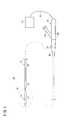
図1は、本発明の一実施形態に係る瘤治療デバイス10の構成を示す一部省略側面図である。この瘤治療デバイス10は、カテーテル11(図4A等参照)に挿通可能なシャフト12と、シャフト12に連結されたバルーン14と、シャフト12とバルーン14とを離脱可能に連結する離脱機構16とを備え、処置対象の瘤内でバルーン14を拡張させて当該バルーン14を瘤の内表面の少なくとも一部に密着させ、瘤の内表面に密着させたバルーン14を瘤とともに収縮させ、その後、バルーン14を瘤とともに収縮させた状態でシャフト12からバルーン14を離脱させることにより、瘤内部の血圧を下げて瘤の破裂を予防する治療をするためのデバイスである。以下、各構成要素の構成を説明する。 FIG. 1 is a partially omitted side view showing the configuration of an
図1に示すように、シャフト12は、可撓性を有する長尺で線状(ワイヤ状)の部材であり、瘤治療デバイス10の使用に際して、シャフト12の先端部にバルーン14が連結された状態でカテーテル11内に挿通され、カテーテル11内でバルーン14を先端方向に進めるためのプッシャとして機能するとともに、バルーン14の拡張及び収縮を行うための拡張用流体(例えば、造影剤や生理食塩液)を流すためのチューブとして機能する。 As shown in FIG. 1, the
図3A及び図3Bに示すように、シャフト12には、第1のルーメンとして、拡張用流体の流路として機能する拡張用ルーメン20が設けられるとともに、第2のルーメンとして、後述する離脱機構16の駆動ワイヤ40が挿通された駆動部材用ルーメン22とが設けられている。拡張用ルーメン20は、駆動部材用ルーメン22よりも大径である。拡張用ルーメン20と駆動部材用ルーメン22とは、シャフト12内でシャフト12の軸線に沿って、シャフト12の基端部まで並列に延在している。 As shown in FIGS. 3A and 3B, the
シャフト12は、生体内の管腔(血管等)に挿入されて管腔内を走行する際にカテーテル11とともに管腔の湾曲に容易に追従できる程度の柔軟性を有するとともに、カテーテル11からバルーン14を押し出すことができるような適度の剛性を有することが好ましい。 The
そこで、シャフト12は、金属や樹脂が挙げられる。金属としては、例えば、Ni−Ti系合金のような擬弾性合金(超弾性合金を含む)、形状記憶合金、ステンレス鋼(例えば、SUS304、SUS303、SUS316、SUS316L、SUS316J1、SUS316J1L、SUS405、SUS430、SUS434、SUS444、SUS429、SUS430F、SUS302等、SUSの全品種)、コバルト系合金、金、白金のような貴金属、タングステン系合金、炭素系材料(ピアノ線を含む)等が挙げられる。樹脂としては、例えば、ポリオレフィン(例えば、ポリエチレン、ポリプロピレン、ポリブテン、エチレン−プロピレン共重合体、エチレン−酢酸ビニル共重合体、アイオノマー、或いはこれら二種以上の混合物等)、ポリ塩化ビニル、ポリアミド、ポリアミドエラストマー、ポリエステル、ポリエステルエラストマー、ポリウレタン、ポリウレタンエラストマー、ポリイミド、フッ素樹脂等の高分子材料或いはこれらの混合物、或いは上記2種以上の高分子材料の多層チューブ等により構成され得る。 Therefore, the
シャフト12の寸法は、治療対象部位に応じて適宜選択されるが、例えば、脳動脈瘤の治療に使用される場合には、全長が800〜1500mm、外径が0.6〜3mm程度に設定される。シャフト12の先端にはX線透視下で認識可能なようにX線非透過性マーカーが設置されていてもよい。 The dimensions of the
図1に示すように、シャフト12の基端部には、操作者が把持するための、シャフト12よりも大径のグリップ部18(ハブ)が接続されている。グリップ部18は、グリップ本体24と、グリップ本体24から分岐した拡張用ポート26とを有している。拡張用ポート26は、拡張用流体を圧送可能な図示しないインデフレーター等の圧力印加装置が接続可能である。拡張用ポート26に圧力印加装置が接続された状態で、当該圧力印加装置は拡張用ポートの内腔及び拡張用ルーメン20を介してバルーン14の内部に連通する。 As shown in FIG. 1, a grip portion 18 (hub) having a diameter larger than that of the
グリップ部18には、さらに、離脱機構16を動作させる際に操作する操作子28(操作ノブ)が設けられている。本実施形態において、操作子28は、グリップ部18において操作者が手指で容易に操作可能な位置に、グリップ本体24に対して軸線方向に変位自在に設けられ、離脱機構16の駆動ワイヤ40に連結されている。操作子28の作用については、後述する。 The
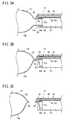
バルーン14は、シャフト12の先端部に連結されており、拡張用ルーメン20からの拡張用流体による内圧の変化によって拡張及び収縮(折り畳み)が可能となっている。図3Aに示すように、バルーン14は、バルーン14の本体を構成する袋状の拡張部14aと、シャフト12に固定され流通口15aを有する基端部14bと、拡張部14aと基端部14bとの間を構成する根元部14cとからなり、基端部14bが、固定リング30を介してシャフト12の拡張用ルーメン20の内周面に固定され、当該基端部14bに設けられた流通口15aを介して、バルーン14内と拡張用ルーメン20とが連通している(図3A参照)。基端部14bの外周面が固定リング30の内周面に液密に固着され、固定リング30の外周面が拡張用ルーメン20の内周面に液密に固着されることにより、シャフト12とバルーン14とが液密に連結されている。さらに、バルーン14の基端部の内周面に別の固定リング(図示しない)が固定されていてもよい。バルーン14の基端部は内外から固定リングで固着されることにより、より強固に固定される。 The
拡張用ポート26に図示しない圧力印加装置を接続し、圧力印加装置を操作して拡張用流体を拡張用ポート26の内腔及び拡張用ルーメン20を介してバルーン14内に導入すると、バルーン14が拡張する。一方、当該圧力印加装置を操作して拡張用流体を拡張用ルーメン20及び拡張用ポート26の内腔を介してバルーン14内から排出すると、バルーン14が収縮する。図1では、収縮状態のバルーン14を実線で、拡張状態のバルーン14を仮想線で示している。 When a pressure application device (not shown) is connected to the
バルーン14を瘤内で拡張させた際にバルーン14の外表面と瘤の内表面とが接着するように、バルーン14の外表面の一部又は全体に、接着性コーティング32が施されることが好ましい。接着性コーティング32としては、例えば、ハイドロゲル等の親水性ポリマーがある。親水性ポリマーとしては、例えば、ポリヒドロキシエチルメタクリレート、ポリヒドロキシエチルアクリレート、ポリビニルアルコール、ポリビニルピロリドン、ポリ乳酸、ポリエチレングリコールが挙げられる。 An
バルーン14は、その内部に対する拡張用流体の供給及び排出により拡張及び収縮が可能な程度の柔軟性を有し、且つ実用上適度な強度を有するものであれば、特にその構成材料は限定されないが、例えば、シャフト12の構成材料として例示したものから構成され得る。或いは、バルーン14は、シャフト12よりも柔軟で伸縮性を有する材料により構成されてもよく、例えば、天然ゴム、ブチルゴム、イソプレンゴム、ブタジエンゴム、スチレン−ブタジエンゴム、シリコーンゴムのような各種ゴム材料や、ポリウレタン系、ポリエステル系、ポリアミド系、オレフィン系、スチレン系等の各種熱可塑性エラストマー、あるいはそれらの混合物等により構成され得る。 The material of the
バルーン14の寸法は、治療対象部位に応じて適宜選択されるが、例えば、脳動脈瘤の治療に使用される場合には、全長が2〜50mm、収縮時の外径が0.4〜2mm程度、拡張部14aの拡張時の外径が5〜50mm程度、バルーン14を構成する壁部の厚さが0.05〜0.3mmに設定される。 The dimensions of the
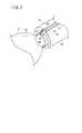
図2、図3A及び図3Bに示すように、離脱機構16は、バルーン14の根元部14cを絞るための絞り部36と、根元部14cが絞られたバルーン14を溶融させるヒータ38とを備える。絞り部36は、駆動ワイヤ40における、駆動部材用ルーメン22の先端から引き出されてループ状とされた部分により形成されており、バルーン14の根元部14cを囲うように配置されている。換言すれば、駆動ワイヤ40のループ状の内側に、バルーン14の根元部14cが挿通されている。 As shown in FIGS. 2, 3A and 3B, the
駆動ワイヤ40は、駆動部材用ルーメン22内に挿通されて、その基端側はシャフト12の基端面から突出し、図1に示すように、グリップ本体24内で、操作子28の一部と連結されている。このため、操作子28を基端方向にスライド操作すると、当該操作子28に連結された駆動ワイヤ40が基端方向に引っ張られる。なお、本実施形態では、操作子28の操作方向とそれに連動する駆動ワイヤ40の移動方向とは同じであるが、操作子28の操作方向と駆動ワイヤ40の移動方向とが異なるように構成してもよい。例えば、操作子28を先端方向にスライド操作すると、駆動ワイヤ40が基端方向に移動するように構成してもよい。 The
ヒータ38は、バルーン14の根元部14cに接触する位置、具体的には、絞り部36によりバルーン14の根元部14cが絞られた際に当該絞られた根元部14cを加熱して溶融させることができる位置に配置されている。ヒータ38には、第1の導線42と第2の導線43の先端部が連結されており、当該第1及び第2の導線42、43を介してヒータ38に通電することにより、ヒータ38が加熱する。第1及び第2の導線42、43は、シャフト12に沿って、グリップ部18まで配設され、さらに、ケーブル19を介して電源21に接続されている。電源21は、直流、交流のいずれでもよい。 The
なお、図3A及び図3Bでは、図示の便宜上、第1及び第2の導線42、43が拡張用ルーメン20の内面に沿って配設された状態が示されているが、第1及び第2の導線42、43を挿通させる独立したルーメンをシャフト12に設けてもよく、或いは、第1及び第2の導線42、43をシャフト12に埋設してもよい。 3A and 3B show a state in which the first and second
なお、図3Cではバルーン14が拡張した状態で離脱しているが、本発明の治療方法においては後述のとおり、瘤と共に収縮した状態でバルーン14がシャフト12から離脱する。 In FIG. 3C, the
このように構成された離脱機構16は、以下のように動作する。操作子28に対する操作によって駆動ワイヤ40が基端方向に引っ張られると、駆動ワイヤ40の先端部に形成されたループ状の絞り部36が縮小していく。その際、絞り部36の内側に配置されたバルーン14の根元部14cは、縮小していく絞り部36によって絞られていく。駆動ワイヤ40の引き量がある程度まで達すると、図3Bに示すように、バルーン14は、根元部14cで内部流路が完全に閉塞した状態となる。そして、この状態でヒータ38に通電して発熱させると、絞られたバルーン14の根元部14cが加熱されることで、図3Cに示すように溶融し分断されるに至る。これにより、シャフト12からバルーン14が離脱される。これらの絞り部36やヒータ38は交互に隣接して複数が配置されていてもよい。なお、本発明において、離脱機構16は、バルーン14をシャフト12から分離できるものであれば上述した構成に限られず、種々の構成を採用し得る。離脱機構16の代替的構成については、後述する。 The
本実施形態に係る瘤治療デバイス10は、基本的には以上のように構成されるものであり、以下では、瘤治療デバイス10の使用方法(瘤治療方法)との関係で、瘤治療デバイス10の作用及び効果について説明する。瘤治療デバイス10を用いた瘤治療方法は、以下の工程を有する。 The
(1) アクセスステップ(第1ステップ)
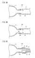
図4Aに示すように、カテーテル11内を通して、瘤治療デバイス10を治療対象部位である瘤の近傍に配置する。治療対象となる瘤62は中空の袋状組織である。瘤62は管腔組織から一部が外側に向かって膨大するように外表面が突出した部分からなる。突出した部分は内部に空間を有し、この空間が管腔内に開口部を介して連通している。瘤62は外部に突出した部分が袋状の構造を形成し、袋状の内部の空間は組織の一部により形成される膜状組織により外部と内部が隔てられている。瘤62は管腔との開口部が狭くなり頸部を形成していたり、または開口部が比較的大きく頸部を有さないものもある。瘤62の例としては、例えば、脳動脈瘤、腹部動脈瘤、胸部動脈瘤、冠状動脈瘤、膝窩動脈瘤、大腿動脈瘤、頸動脈瘤等である。このアクセスステップでは、具体的には、ガイドワイヤを挿通したカテーテル11を血管60内に走行させ、カテーテル11の先端が瘤62の開口部近傍又は瘤62内部まで到達させる。ガイドワイヤは先端がアングル付けされており、当該ガイドワイヤを押し引き操作することによりカテーテル11先端の向きを調整し、カテーテル11の先端を瘤62の開口部又は瘤62内部に配置する。その後、カテーテル11からガイドワイヤを抜去し、瘤治療デバイス10をカテーテル11に挿入する。(1) Access step (first step)
As shown in FIG. 4A, the
(2) バルーン挿入ステップ(第2ステップ)
次に、図4Bに示すように、カテーテル11の位置を保持した状態で、シャフト12を先端方向に進めることにより、バルーン14をカテーテル11から押し出し、バルーン14を瘤62内に挿入する。瘤62に頸部がある場合、シャフト12は狭い頸部の内径を押し広げるようにして頸部に進入する。(2) Balloon insertion step (second step)
Next, as shown in FIG. 4B, the
(3) バルーン拡張ステップ(第3ステップ)
バルーン14を瘤内に挿入したら、次に、図4Cに示すように、バルーン14を瘤内で拡張させ、バルーン14の外表面を瘤62の内表面に密着させる。具体的には、図示しない圧力印加装置をグリップ部18(図1参照)に設けられた拡張用ポート26に接続し、圧力印加装置により、グリップ部18及びシャフト12を介してバルーン14内に拡張用流体を導入する。これにより、バルーン14が拡張する。バルーン14が拡張していく過程で、バルーン14と瘤62との間に存在する血液は、瘤62の開口部(根元)から血管(親血管)へと流出する。やがてバルーン14の外表面が瘤62の内表面に接触又は密着し、バルーン14と瘤62との間から血液が排出された状態となる。この場合、バルーン14の外表面の全体が瘤62の内表面に接触している必要はなく、バルーン14の外表面の大部分が瘤62の内表面に接触し、密着すればよい。バルーン14を拡張させる際、瘤62内の血液をほぼ排除するために、瘤62が破裂しない程度に瘤62内部よりもわずかに大きくバルーン14を拡張(過拡張)させてもよい。(3) Balloon expansion step (third step)
Once the
(4) バルーン収縮ステップ(第4ステップ)
バルーン14の外表面を瘤62の内表面に密着させたら、次に、図5A及び図5Bに示すように、バルーン14を収縮させる。具体的には、圧力印加装置を操作して、バルーン14内から拡張用流体を排出することにより、バルーン14を収縮させる。この場合、バルーン14の外表面と瘤62の内表面とは密着しているので、バルーン14の収縮とともに瘤62も一緒に収縮する。従って、血管60からの血液がバルーン14と瘤62の間に再流入することなく、バルーン14と瘤62とが同時に収縮していく。瘤62に頸部がある場合、収縮したバルーン14が頸部の径よりも大きくなることがある。このような場合、収縮したバルーン14は頸部内で頸部の圧力に押されて固定される。このとき、頸部で圧迫固定されたバルーン14の根元部ではバルーン拡張用流体の流通は阻止されている。またバルーン14の根元部の外側と頸部の内側での血液の流通も阻止されている。(4) Balloon deflation step (fourth step)
Once the outer surface of the
本実施形態の場合、バルーン14の外表面に接着性コーティング32が施されていてもよいので、その場合バルーン14の外表面が瘤62の内表面によく接着する。なお、バルーン14の外表面に接着性コーティング32が施されていない場合でも、バルーン14の外表面を瘤62の内表面に十分に密着させることにより、バルーン14と瘤62との間に血液が流入することが阻止されるため、バルーン14とともに瘤62を同時に収縮させることができる。 In the present embodiment, the
(5) 離脱ステップ(第5ステップ)
バルーン14内から拡張用流体を略完全に排出することにより、バルーン14及び瘤62を図5Bのように収縮させたら、次に、図5Cに示すように、離脱機構16の作用下に、シャフト12からバルーン14を離脱させる。シャフト12からバルーン14を離脱させるとき、瘤62はバルーン14とともに収縮している。離脱機構16の場合、図3Bに示したように、先ず絞り部36でバルーン14の根元部14cを絞る(絞りステップ)。この絞りステップにより、バルーン14とシャフト12との連通が遮断された状態となる。次に、絞られた根元部14cをヒータ38で加熱して、当該根元分を溶融破断させる(溶融ステップ)。これにより、シャフト12からバルーン14を離脱させることができる。シャフト12からバルーン14を離脱させた後も、瘤62はバルーン14とともに収縮した状態で保持されている。瘤62に頸部がある場合、収縮したバルーン14の根元部が頸部で固定され、バルーン拡張用流体の流通も阻止されているため、頸部付近から血液が瘤62の内部に流入することが阻止されている。またこの状態でバルーン14の根元部の外側と頸部の内側での血液の流通も阻止されている。(5) Leave step (fifth step)
When the
以上説明したように、本実施形態に係る瘤治療デバイス10によれば、カテーテル11内に瘤治療デバイス10を挿通して血管に発生した瘤62にアクセスし、瘤62内でバルーン14を拡張させることでバルーン14を瘤62の内表面に密着させ、その後、バルーン14と瘤62の内表面と密着させたまま、バルーン14とともに瘤62を収縮させる手技を行うことができる。このような手技により、瘤62内から血液が排出されることから、瘤62内の血圧を下げて瘤62の破裂の危険性を効果的に低減できる。 As described above, according to the
本実施形態の場合、瘤62を収縮させることで瘤62の内容積が減少するので、周辺組織への影響を低減することができる。すなわち、例えば、脳動脈瘤の場合、脳動脈瘤の大きさが縮小することにより、脳動脈瘤の周囲にある脳組織への圧迫を軽減でき、治療効果を一層高めることができる。 In the case of the present embodiment, the inner volume of the
また、本実施形態の場合、バルーン14の外表面に接着性コーティング32が施されていてもよいので、瘤62の内表面に密着させたバルーン14を収縮させる際に、バルーン14の収縮とともに瘤62を確実に収縮させることができる。このため、瘤62内への血液の再流入が防止され、高い治療効果が得られる。 In the present embodiment, since the
さらに、本実施形態の場合、離脱機構16は、バルーン14の根元部14cを絞るための絞り部36と、根元部14cが絞られた前記バルーン14を溶融させるヒータ38とを備えるので、バルーン14の根元部14cを絞ったうえで根元部14cを溶融させるので、シャフト12からバルーン14を確実に離脱させることができる。 Further, in the case of the present embodiment, the
次に、瘤治療デバイス10について、いくつかの変形例を説明する。図6に示す第1変形例に係るシャフト12aのように、拡張用ルーメン20及び駆動部材用ルーメン22に平行してガイドワイヤルーメン44をシャフト12aの軸線方向に沿って設けてもよい。このように構成されたシャフト12aによれば、ガイドワイヤルーメン44にガイドワイヤを挿通させた状態で使用することにより、瘤治療デバイス10をカテーテル11内で進め易くなり、操作性を向上させることができる。 Next, some modified examples of the
図7A及び図7Bに示す第2変形例に係るシャフト12bのように、シャフト12bの先端部にバルーン14の収納部46を設けてもよい。具体的には、シャフト12bとバルーン14との結合部(固定リング30)は、シャフト12bの先端面に対して基端方向に離間した位置に設けられている。シャフト12bの先端面と結合部との間が、バルーン14の収納部46として構成されている。すなわち、シャフト12bの先端部を構成する筒状の管壁47の内側に、シャフト12bの軸線方向に所定長さ延在する収納部46が構成されている。図7Aでは、バルーン14は、螺旋状にねじられてシャフト12bの軸線方向に沿う寸法が小さくされた状態で収納部46に収納されている。シャフト12bにおいて、図6に示したシャフト12aと同様に、ガイドワイヤルーメン44を設けてもよい。 As in the
上記のように構成されたシャフト12bによれば、瘤治療デバイス10をカテーテルに挿通させる際に、バルーン14を収縮させた状態でシャフト12bの先端部に確実に保持しておくことができるので、カテーテル内壁とシャフト12bとの間にバルーン14が入り込むことが防止される。従って、バルーン14の損傷を防止することができるとともに、手技を円滑に遂行することができる。バルーン14内に拡張用流体が導入されると、図7Bに示すように、バルーン14は、拡張用流体によって軸線方向に伸張して拡張部14aがシャフト12の先端部から突出するとともに、シャフトの先端部から突出した拡張部14aが拡張する。 According to the
図8A〜図8Cに示す離脱機構16aは、バルーン14の根元部14cを絞るための絞り部として機能するとともにバルーン14の根元部14cを溶融させるヒータとして機能する、導電性を有する分離ワイヤ50を備える。この離脱機構16aは、図3A等に示した離脱機構16と異なり、バルーン14の根元部14cを絞る機構とは別個独立したヒータを備えておらず、分離ワイヤ50が、バルーン14の根元部14cを絞る機能と、根元部14cを溶融させるヒータとしての機能を兼ね備えている。従って、分離ワイヤ50のうち、駆動部材用ルーメン22の先端から引き出されてループ状に形成された分離部50aは、通電によってバルーン14の根元部14cを溶融できる程度に発熱可能な材料からなり、バルーン14の根元部14cを囲うように形成されている。分離ワイヤ50のうち、駆動部材用ルーメン22に挿通された引張部50bは、主として分離部50aへの電力を供給する動力線として機能する部分であるため、通電による発熱でシャフト12を溶融することがない材料からなるのがよい。分離ワイヤ50は、その基端で、図1の構成と同様に、グリップ部18に設けられた操作子28に連結される。 The
このように構成された離脱機構16aは、以下のように動作する。操作子28に対する操作によって分離ワイヤ50が基端方向に引っ張られると、分離ワイヤ50の先端部に形成されたループ状の分離部50aが縮小していく。その際、分離部50aの内側に配置されたバルーン14の根元部14cは、縮小していく分離部50aによって絞られていく。分離ワイヤ50の引き量がある程度まで達すると、図8Bに示すように、バルーン14は、根元部14cで内部流路が完全に閉塞した状態となる。そして、この状態で分離部50aに通電して発熱させると、絞られたバルーン14の根元部14cが加熱されることで、図8Cに示すように溶融し分断されるに至る。これにより、シャフト12からバルーン14が離脱される。 The
上記のように構成された離脱機構16aによれば、分離ワイヤ50が、バルーン14の根元部14cを絞る機能と、バルーン14の絞られた根元部14cを溶融させる機能とを兼ね備えるため、シャフト12からバルーン14を離脱させるための機構を簡素な構成で実現できる。 According to the
なお、図8Cではバルーン14が拡張した状態で離脱しているが、本発明の治療方法においては前述のとおり、瘤62とともに収縮した状態でバルーン14がシャフト12から離脱する。 8C, the
離脱機構16の変形例としては、上記した離脱機構16aの他、別々に構成された2つの部材を物理的な係合(嵌合、引っ掛かり等)により離脱可能に連結した構成や、ある部材を何らかの物理的作用(熱的作用、化学的作用等)により分断することにより離脱可能に連結した構成を採用し得る。これらの変形例では、バルーン14の根元部を絞る機構(絞り部)が省略されているが、前出の絞り部の具体例を採用することができる。 As a modified example of the
図9Aに示す第2変形例に係る離脱機構16bは、バルーン14の基端部14bの外周面に固着された嵌合リング52とシャフト12とが嵌合する構成となっている。嵌合リング52とシャフト12との嵌合力(結合力)は、両者を離脱させようとする力が所定未満までは嵌合して連結状態を維持するが、所定以上の力が作用した際には、嵌合が外れることで、バルーン14とシャフト12とが離脱するような嵌合力に設定されている。 The
このように構成された離脱機構16bによれば、バルーン14を瘤62とともに収縮させ且つカテーテル11を固定した状態で、シャフト12を周方向に回転させるか又は後退移動させることにより、シャフト12の先端部と嵌合リング52との嵌合力を超える力がかかると、嵌合が外れるので、バルーン14をシャフト12から離脱させることができる。 According to the
なお、図9Aでは、嵌合リング52がシャフト12の拡張用ルーメン20に先端側から挿入され、両者が嵌合するように構成されているが、嵌合のオスメスの関係を逆にした構成であってもよい。すなわち、基端部14bの内周面に嵌合リングを固着し、当該嵌合リングにシャフト12の先端を内嵌した構成でもよい。 In FIG. 9A, the
図9Bに示す第3変形例に係る離脱機構16cは、バルーンの基端部14bの外周面に固着された螺合リング54とシャフト12とが螺合する構成となっている。具体的には、螺合リング54の外周部に雄ネジ54aが形成され、シャフト12の内周部に雌ネジ55が形成されている。螺合リング54とシャフト12との螺合力(結合力)は、両者間に作用するトルクが所定未満までは螺合を維持するが、所定以上のトルクが作用した際には、螺合が外れることで、バルーン14とシャフト12とが離脱するように設定されている。 The
このように構成された離脱機構16cによれば、バルーン14を瘤62とともに収縮させ且つカテーテル11を固定した状態で、シャフト12を周方向に回転させることにより、シャフト12の先端部と螺合リング54との螺合が外れるので、バルーン14をシャフト12から離脱させることができる。 According to the
なお、図9Bでは、螺合リング54に設けられた雄ネジ54aがシャフト12に設けられた雌ネジ55に螺合することで、バルーン14とシャフト12とが連結するように構成されているが、螺合のオスメスの関係を逆にした構成であってもよい。すなわち、内周面に雌ネジが形成された螺合リングを基端部14bの内周面に固着し、シャフト12の先端部の外周面に、当該雌ネジと螺合する雄ネジを形成した構成であってもよい。 9B, the
図9Cに示す第4変形例に係る離脱機構16dは、バルーン14の基端部14bとシャフト12の先端とを連結する連結部56と、連結部56の外周にコイル状に巻きつけられたヒータ57と、ヒータ57に接続された第1及び第2の導線58、59とを備える。連結部56は、加熱されることにより溶融して破断することが可能な材料(例えば、樹脂、低融点金属等)からなる。第1の導線58はヒータ57の一端に接続され、第2の導線59はヒータ57の他端に接続され、第1及び第2の導線58、59はシャフト12内に挿通されてヒータ57に接続された側とは反対側の端部にて電源21(図1参照)に接続されている。このように構成された離脱機構16dによれば、第1及び第2の導線58、59を介してヒータ57に通電して発熱させることで、連結部56を溶融破断させることにより、バルーン14をシャフト12から離脱させることができる。 9C includes a connecting
離脱機構16の他の変形例としては、バルーン14とシャフト12の先端とを金属製の連結部で連結し、当該連結部を電気分解することによりシャフト12からバルーン14を離脱させる構成や、接続部分に流体圧をかけ、シャフト12からバルーン14の基端部14bを押し出して離脱させる構成を採用し得る。 Other modified examples of the
上記において、本発明について好適な実施形態を挙げて説明したが、本発明は前記実施形態に限定されるものではなく、本発明の要旨を逸脱しない範囲において、種々の改変が可能なことは言うまでもない。 In the above description, the present invention has been described with reference to preferred embodiments. However, the present invention is not limited to the above-described embodiments, and various modifications can be made without departing from the scope of the present invention. Yes.
10…瘤治療デバイス 11…カテーテル
12、12a、12b…シャフト 14…バルーン
14a…拡張部 14b…基端部
14c…根元部 16、16a〜16d…離脱機構
32…接着性コーティング 36…絞り部
38…ヒータ 40…駆動ワイヤ
46…収納部 50…分離ワイヤDESCRIPTION OF
Claims (5)
Translated fromJapanese前記シャフトの先端部に連結され、拡張及び収縮が可能なバルーンと、
前記シャフトと前記バルーンとを離脱可能に連結する離脱機構とを備え、
生体内に生じた瘤内で前記バルーンが拡張した際に前記バルーンが前記瘤の内表面の少なくとも一部に密着し、前記瘤の内表面に密着した前記バルーンが収縮した際に前記瘤が前記バルーンとともに収縮するように構成されている
ことを特徴とする瘤治療デバイス。A linear shaft having flexibility;
A balloon connected to the tip of the shaft and capable of expansion and contraction;
A release mechanism for releasably connecting the shaft and the balloon;
When the balloon is expanded in the aneurysm formed in the living body, the balloon is in close contact with at least a part of the inner surface of the aneurysm, and the aneurysm is in contact with the inner surface of the aneurysm when the balloon is contracted. An aneurysm treatment device configured to contract with a balloon.
前記シャフトと前記バルーンとの結合部は、前記シャフトの先端に対して基端方向に離間した位置に設けられ、
前記シャフトの先端面と前記結合部との間は、前記バルーンの収納部として構成されている
ことを特徴とする瘤治療デバイス。The aneurysm treatment device according to claim 1, wherein
The joint between the shaft and the balloon is provided at a position spaced in the proximal direction with respect to the distal end of the shaft,
An aneurysm treatment device characterized in that a space between the distal end surface of the shaft and the coupling portion is configured as a housing portion for the balloon.
前記離脱機構は、前記バルーンの根元部を絞る絞り部と、前記根元部が絞られた前記バルーンを溶融させるヒータとを備える
ことを特徴とする瘤治療デバイス。The aneurysm treatment device according to claim 1 or 2,
The aneurysm treatment device comprising: a squeezing part that squeezes a base part of the balloon; and a heater that melts the balloon in which the base part is squeezed.
前記離脱機構は、前記バルーンの根元部を絞るための絞り部として機能するとともに前記バルーンの根元部を溶融させるヒータとして機能する分離ワイヤを備える
ことを特徴とする瘤治療デバイス。The aneurysm treatment device according to any one of claims 1 to 3,
The detachment mechanism includes a separation wire that functions as a constriction unit for constricting the root part of the balloon and also functions as a heater that melts the base part of the balloon.
前記瘤内に前記バルーンを挿入する第2ステップと、
前記瘤内で前記バルーンを拡張させ、前記バルーンの外表面を前記瘤の内表面に密着させる第3ステップと、
前記バルーンの外表面を前記瘤の内表面に密着させた状態で、前記バルーンを前記瘤とともに収縮させる第4ステップと、
前記バルーンを前記シャフトから離脱させる第5ステップとを含む
ことを特徴とする瘤治療方法。An aneurysm treatment device having a configuration in which a balloon that can be expanded and contracted is connected to the tip of a shaft through a detachment mechanism through a catheter inserted into a blood vessel and delivered to a position where the aneurysm is a treatment target site The first step;
A second step of inserting the balloon into the aneurysm;
A third step of expanding the balloon within the aneurysm and bringing the outer surface of the balloon into intimate contact with the inner surface of the aneurysm;
A fourth step of shrinking the balloon together with the aneurysm with the outer surface of the balloon in close contact with the inner surface of the aneurysm;
And a fifth step of detaching the balloon from the shaft.
Priority Applications (1)
| Application Number | Priority Date | Filing Date | Title |
|---|---|---|---|
| JP2012012622AJP2013150687A (en) | 2012-01-25 | 2012-01-25 | Aneurysm treatment device and aneurysm treatment method |
Applications Claiming Priority (1)
| Application Number | Priority Date | Filing Date | Title |
|---|---|---|---|
| JP2012012622AJP2013150687A (en) | 2012-01-25 | 2012-01-25 | Aneurysm treatment device and aneurysm treatment method |
Publications (1)
| Publication Number | Publication Date |
|---|---|
| JP2013150687Atrue JP2013150687A (en) | 2013-08-08 |
Family
ID=49047620
Family Applications (1)
| Application Number | Title | Priority Date | Filing Date |
|---|---|---|---|
| JP2012012622APendingJP2013150687A (en) | 2012-01-25 | 2012-01-25 | Aneurysm treatment device and aneurysm treatment method |
Country Status (1)
| Country | Link |
|---|---|
| JP (1) | JP2013150687A (en) |
- 2012
- 2012-01-25JPJP2012012622Apatent/JP2013150687A/enactivePending
Similar Documents
| Publication | Publication Date | Title |
|---|---|---|
| JP2013153810A (en) | Knob treatment device and knob treatment method | |
| JP6463817B2 (en) | Detachable metal balloon delivery device and method | |
| US7208003B2 (en) | Reattachable introducer for a medical device deployment system | |
| EP1400209B1 (en) | Detachable introducer for a medical device deployment system | |
| US10653869B2 (en) | Balloon catheter | |
| JP2002017736A (en) | Hydraulic arrangement system for small-diameter plugging coil | |
| JPH07265431A (en) | Wire for medical treatment having in-vivo indwelling member | |
| CN105392447A (en) | Expandable body devices and methods of use | |
| KR20130111420A (en) | Embolic coil detachment mechanism with flexible distal member and resistive electrical heating element | |
| JP2013527001A (en) | Balloon catheter | |
| JP5208380B2 (en) | Chemical-based placement of vaso-occlusive devices | |
| EP1307145B1 (en) | Intravascular delivery system | |
| JP2003265614A (en) | Balloon catheter | |
| JP2014200371A (en) | Balloon catheter and use method thereof | |
| JP2013150687A (en) | Aneurysm treatment device and aneurysm treatment method | |
| US7670353B2 (en) | Modified headpiece for hydraulic coil deployment system | |
| JPH01238874A (en) | Inductor capable of separating storage member in vivo from its tip | |
| JP2013179963A (en) | Bump treatment device and bump treatment method | |
| JP2013154087A (en) | Device assembly for aneurysm treatment and aneurysm treatment method | |
| JP2013183803A (en) | Bump treating device assembly and bump treating method | |
| KR101196730B1 (en) | Balloon catheter | |
| JP2013150694A (en) | Aneurysm treatment device and aneurysm treatment method | |
| JP2013150686A (en) | Aneurysm treatment device and aneurysm treatment method | |
| EP3313467B1 (en) | Catheter comprising a detachable polymer bond | |
| JP2013154028A (en) | Knob treatment device assembly and knob treatment method |