JP2013149907A - Wiring connection structure between two substrates - Google Patents
Wiring connection structure between two substratesDownload PDFInfo
- Publication number
- JP2013149907A JP2013149907AJP2012011115AJP2012011115AJP2013149907AJP 2013149907 AJP2013149907 AJP 2013149907AJP 2012011115 AJP2012011115 AJP 2012011115AJP 2012011115 AJP2012011115 AJP 2012011115AJP 2013149907 AJP2013149907 AJP 2013149907A
- Authority
- JP
- Japan
- Prior art keywords
- electronic circuit
- wiring
- circuit board
- housing
- board
- Prior art date
- Legal status (The legal status is an assumption and is not a legal conclusion. Google has not performed a legal analysis and makes no representation as to the accuracy of the status listed.)
- Pending
Links
Images


Landscapes
- Power Steering Mechanism (AREA)
- Combinations Of Printed Boards (AREA)
Abstract
Translated fromJapaneseDescription
Translated fromJapaneseこの発明は、2つの基板間の配線接続構造に関する。 The present invention relates to a wiring connection structure between two substrates.
電動パワーステアリング装置は、操舵補助力を発生する電動モータを備えている。この電動モータが、トルクセンサによって検出される操舵トルクに基づいて駆動制御されることにより、操舵状況に応じた適切な操舵補助が実現される。電動モータを制御するための制御回路が搭載された制御基板とトルクセンサとは、信号線によって接続されている。 The electric power steering apparatus includes an electric motor that generates a steering assist force. The electric motor is driven and controlled based on the steering torque detected by the torque sensor, thereby realizing appropriate steering assistance according to the steering situation. A control board on which a control circuit for controlling the electric motor is mounted and the torque sensor are connected by a signal line.
本願発明者は、トルクセンサと制御基板とをフレキシブル基板によって接続することを考案した。この場合、フレキシブル基板の回路配線によって、トルクセンサと制御基板の回路配線とが接続される。フレキシブル基板と制御基板との配線接続は、フレキシブル基板の一端側に形成された接続端子が制御基板の回路配線に半田接合されることによって行なわれる。そうすると、水、油等の液体が制御基板の表面を伝って半田接合部に侵入し、半田接合部が劣化したり、隣接する半田接合部が短絡したりするおそれがある。 The inventor of the present application devised connecting the torque sensor and the control board by a flexible board. In this case, the torque sensor and the circuit wiring of the control board are connected by the circuit wiring of the flexible board. The wiring connection between the flexible board and the control board is performed by soldering connection terminals formed on one end of the flexible board to the circuit wiring of the control board. If it does so, liquids, such as water and oil, penetrate | invade into a solder joint part along the surface of a control board, and there exists a possibility that a solder joint part may deteriorate or an adjacent solder joint part may short-circuit.
この発明の目的は、第1電子回路基板の回路配線とフレキシブル基板からなる第2電子回路基板の接続端子との接合部に液体が浸入するのを防止できる2つの基板間の配線接続構造を提供することである。
この明細書において、「電子回路基板」には、「電子部品が半田付けされておらず、配線だけの状態のもの」および「電子部品が半田付けされて電子回路として動作するようになったもの」のいずれも含まれるものとする。An object of the present invention is to provide a wiring connection structure between two substrates that can prevent liquid from entering the joint between the circuit wiring of the first electronic circuit board and the connection terminal of the second electronic circuit board made of a flexible substrate. It is to be.
In this specification, "electronic circuit board" includes "electronic components not soldered, only in the state of wiring" and "electronic components are soldered to operate as electronic circuits""Is included.
請求項1に記載の発明は、第1電子回路基板(60)と第2電子回路基板(70)とからなる2つの基板間の配線接続構造であって、前記第2電子回路基板は、一端側に前記第1電子回路基板の回路配線(621)に接続される接続端子(72a)を有するフレキシブル基板からなり、前記第2電子回路基板における前記接続端子を含む一端部が前記第1電子回路基板の一表面内の一部分に重ね合わされた状態で、前記接続端子が前記第1電子回路基板の回路配線(621)に接合されており、前記第1電子回路基板の前記一表面には、前記第2電子回路基板における前記第1電子回路基板への重ね合わせ部(70A)を取り囲むように、前記重ね合わせ部への液体の浸入を防止する液体侵入防止壁(80)が設けられている、2つの基板間の配線接続構造である。なお、括弧内の英数字は、後述の実施形態における対応構成要素等を表すが、むろん、この発明の範囲は当該実施形態に限定されない。以下、この項において同じ。 The invention according to claim 1 is a wiring connection structure between two substrates including a first electronic circuit board (60) and a second electronic circuit board (70), wherein the second electronic circuit board has one end. A flexible substrate having a connection terminal (72a) connected to the circuit wiring (621) of the first electronic circuit board on the side, and one end including the connection terminal in the second electronic circuit board is the first electronic circuit The connection terminal is bonded to the circuit wiring (621) of the first electronic circuit board in a state of being overlapped with a part of one surface of the board, and the one surface of the first electronic circuit board includes the A liquid intrusion prevention wall (80) for preventing liquid from entering the superposed part is provided so as to surround the superposed part (70A) of the second electronic circuit board to the first electronic circuit board. Between two substrates It is a wiring connection structure. In addition, although the alphanumeric character in parentheses represents a corresponding component in an embodiment described later, of course, the scope of the present invention is not limited to the embodiment. The same applies hereinafter.
この発明では、液体進入防止壁によって、水、油等の液体が第1電子回路基板の表面を伝って第2電子回路基板の重ね合わせ部に侵入するのを防止できる。これにより、第2電子回路基板の接続端子と第1電子回路基板の回路配線との接合部に、水、油等の液体が第1電子回路基板の表面を伝って侵入するのを防止できるから、それらの接合部が液体によって劣化したり、隣り合う接合部が短絡したりするのを防止することができる。 In this invention, it is possible to prevent liquid such as water or oil from entering the overlapping portion of the second electronic circuit board through the surface of the first electronic circuit board by the liquid intrusion prevention wall. As a result, it is possible to prevent liquid such as water and oil from entering the junction between the connection terminal of the second electronic circuit board and the circuit wiring of the first electronic circuit board through the surface of the first electronic circuit board. These junctions can be prevented from being deteriorated by the liquid, and adjacent junctions can be short-circuited.
請求項2に記載の発明は、前記液体侵入防止壁は、前記第2電子回路基板の前記重ね合わせ部から遠ざかるほど前記第1電子回路基板との間隔が大きくなるように、前記第1電子回路基板に対して傾斜している請求項1に記載の2つの基板間の配線接続構造である。 According to a second aspect of the present invention, in the first electronic circuit, the liquid intrusion prevention wall is spaced apart from the first electronic circuit board as the distance from the overlapping portion of the second electronic circuit board increases. The wiring connection structure between two substrates according to claim 1, which is inclined with respect to the substrate.
以下では、この発明の実施形態を、添付図面を参照して詳細に説明する。
図1は、本発明の一実施形態に係る2つの基板間の配線接続構造が適用された電動パワーステアリング装置の概略構成を示す模式図である。
電動パワーステアリング装置1は、車両を操向するための操舵部材としてのステアリングホイール2と、このステアリングホイール2の回転に連動して転舵輪3を転舵する転舵機構4と、運転者の操舵を補助するための操舵補助機構5とを備えている。ステアリングホイール2と転舵機構4とは、ステアリングシャフト6および中間軸7を介して機械的に連結されている。Hereinafter, embodiments of the present invention will be described in detail with reference to the accompanying drawings.
FIG. 1 is a schematic diagram showing a schematic configuration of an electric power steering apparatus to which a wiring connection structure between two substrates according to an embodiment of the present invention is applied.
The electric power steering apparatus 1 includes a
ステアリングシャフト6は、ステアリングホイール2に連結された入力軸8と、中間軸7に連結された出力軸9とを含む。入力軸8と出力軸9とは、トーションバー10を介して相対回転可能に連結されている。
ステアリングシャフト6の周囲には、トルクセンサ11が配置されている。トルクセンサ11は、入力軸8および出力軸9の相対回転変位量に基づいて、ステアリングホイール2に与えられた操舵トルクを検出する。The
A
転舵機構4は、ピニオン軸13と、転舵軸としてのラック軸14とを含むラックアンドピニオン機構からなる。ラック軸14の各端部には、タイロッド15およびナックルアーム(図示略)を介して転舵輪3が連結されている。ピニオン軸13は、中間軸7に連結されている。ピニオン軸13は、ステアリングホイール2の操舵に連動して回転するようになっている。ピニオン軸13の先端には、ピニオン16が連結されている。 The steered
ラック軸14は、自動車の左右方向(直進方向に直交する方向)に沿って直線状に延びている。ラック軸14の軸方向の中間部には、ピニオン16に噛み合うラック17が形成されている。このピニオン16およびラック17によって、ピニオン軸13の回転がラック軸14の軸方向移動に変換される。ラック軸14を軸方向に移動させることによって、転舵輪3を転舵することができる。 The
ステアリングホイール2が操舵(回転)されると、この回転が、ステアリングシャフト6および中間軸7を介して、ピニオン軸13に伝達される。そして、ピニオン軸13の回転は、ピニオン16およびラック17によって、ラック軸14の軸方向移動に変換される。これにより、転舵輪3が転舵される。
操舵補助機構5は、操舵補助用の電動モータ18と、電動モータ18の出力トルクを転舵機構4に伝達するための減速機構19とを含む。電動モータ18は、この実施形態では、三相ブラシレスモータからなる。電動モータ18の近傍には、電動モータ18のロータの回転角を検出するための、例えばレゾルバからなる回転角センサ23が配置されている。減速機構19は、ウォーム軸20と、このウォーム軸20と噛み合うウォームホイール21とを含むウォームギヤ機構からなる。減速機構19は、ギヤハウジング32に収容されている。When the
The
ウォーム軸20は、電動モータ18によって回転駆動される。また、ウォームホイール21は、ステアリングシャフト6とは同方向に回転可能に連結されている。ウォームホイール21は、ウォーム軸20によって回転駆動される。
電動モータ18によってウォーム軸20が回転駆動されると、ウォームホイール21が回転駆動され、ステアリングシャフト6が回転する。そして、ステアリングシャフト6の回転は、中間軸7を介してピニオン軸13に伝達される。ピニオン軸13の回転は、ラック軸14の軸方向移動に変換される。これにより、転舵輪3が転舵される。すなわち、電動モータ18によってウォーム軸20を回転駆動することによって、転舵輪3が転舵されるようになっている。The
When the
電動モータ18は、モータ制御装置としてのECU(電子制御ユニット:Electronic Control Unit)12によって制御される。ECU12には、トルクセンサ11によって検出される操舵トルク、回転角センサ23の出力信号、車速センサ24によって検出される車速等が入力されている。ECU12は、電動モータ18の駆動回路と、駆動回路を制御する制御回路とを備えている。駆動回路は、三相インバータ回路からなる。制御回路は、マイクロコンピュータを含んでいる。制御回路は、例えば、操舵トルクと電動モータ18の目標電流値(目標アシストトルク)との関係を車速毎に記憶したマップを用いて、操舵トルクおよび車速に応じた目標電流値を設定し、電動モータ18のモータ電流が目標電流値に等しくなるように駆動回路を駆動する。 The
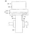
図2は、操舵補助機構5の概略斜視図である。図3は、図2のA方向から見た模式的な矢視図である。
ECU12を収容するためのハウジングHは、互いに接触する第1のハウジング33および第2のハウジング34によって構成されている。第1のハウジング33および第2のハウジング34は、一端が開放した概ね四角箱形に形成されている。第1および第2のハウジング33,34の互いの端部は突き合わされており、固定ねじ51により互いに締結されている。FIG. 2 is a schematic perspective view of the steering assist
The housing H for housing the
一方、電動モータ18を収容するためのモータハウジング35は、筒状のモータハウジング本体36と前記第1のハウジング33とにより構成されている。具体的には、ECU12を収容するためのハウジングHの一部である第1のハウジング33が、電動モータ18のモータハウジング35の少なくとも一部とは単一の材料で一体に形成されている。なお、モータハウジング35には、回転角センサ23も収容されている。 On the other hand, the
また、減速機構19を収容するためのギヤハウジング32は、ウォーム軸20が収容された筒状の駆動ギヤ収容ハウジング37と、ウォームホイール21が収容された筒状の従動ギヤ収容ハウジング38と、前記第2のハウジング34とにより構成されている。具体的には、ECU12を収容するためのハウジングHの一部である第2のハウジング34が、ギヤハウジング32の駆動ギヤ収容ハウジング37および従動ギヤ収容ハウジング38とは単一の材料で一体に形成されている。 The
第1のハウジング33の側壁としての外周壁52の外周には、筒状突起53が突出形成されており、その筒状突起53内には、第1のハウジング33の外部に臨む電気コネクタ54が配置されている。図示していないが、電気コネクタ54には、バッテリーからECU12に電源供給するための端子や、外部からの信号の入出力用の端子が設けられている。 A
モータハウジング本体36は、円筒状の周壁39と、周壁39の一端を閉塞する底壁40と、周壁39の他端からその径方向外方に張り出した環状のフランジ41とを含む。環状のフランジ41の周方向の一部から径方向外方に張り出したブラケット42が設けられている。そのブラケット42のねじ挿通孔43に挿通された固定ねじ44が、第1のハウジング33のねじ孔にねじ込まれることにより、モータハウジング本体36と第1のハウジング33とが一体に固定されている。 The
ギヤハウジング32の従動ギヤ収容ハウジング38には、トルクセンサ11が収容された筒状のセンサハウジング45が連結されており、従動ギヤ収容ハウジング38およびセンサハウジング45は、固定ねじ46を用いて互いに固定されている。ステアリングシャフト6が、従動ギヤ収容ハウジング38およびセンサハウジング45内に挿通されている。 A
図3を参照して、ハウジングH内には、ECU12の一部を構成するパワー基板(図示略)および制御基板60が収容されている。パワー基板には、電動モータ18の駆動回路が実装されている。制御基板60には、電動モータ18の駆動回路を制御するための制御回路が実装されている。制御基板60は、硬質プリント基板(PWB(Printed Wining Board)。リジッド基板)から構成されている。 Referring to FIG. 3, a power board (not shown) and a
トルクセンサ11は、帯状のフレキシブル・プリント基板(FPC(Flexible Printed circuits)。以下、「フレキシブル基板」という。)70を介して、制御基板60の回路配線に電気的に接続されている。フレキシブル基板70の一方の端部はセンサハウジング45内に収容されており、センサハウジング45内おいてフレキシブル基板70の回路配線にトルクセンサ11が電気的に接続されている。フレキシブル基板70の他方の端部は、センサハウジング45内から従動ギヤ収容ハウジング38を通って第2のハウジング34内に進入し、第2のハウジング34内において制御基板60の一端部を廻るように湾曲して制御基板60上に延びている。 The
以下、図4〜図7を参照して、制御基板60とフレキシブル基板70との間の配線接続構造について説明する。図4は、制御基板60とフレキシブル基板70との間の配線接続構造を概略的に示す斜視図である。図5は、図4の平面図である。図6は、図5のVI−VI線に沿う断面図である。図7は、図5のVII−VII線に沿う断面図である。
フレキシブル基板70における制御基板60側の先端寄り部分は、制御基板60の表面に重ね合わされている先端部(以下、「重ね合わせ部70A」という)と、重ね合わせ部70Aの基端から斜め上方に向かって延びた傾斜部70Bと、傾斜部70Bの上端から制御基板60と平行に延びた平行部70Cとを有している。Hereinafter, a wiring connection structure between the
A portion of the
フレキシブル基板70は、基材71と、基材71上に形成された回路配線72と、これらの表面上に形成されたカバーレイフィルム73とを備えている。カバーレイフィルム73は、半田付けが必要な部分には形成されていない。したがって、半田付けが必要な部分においては、回路配線72が露出している。基材71およびカバーレイフィルム73はポリイミド等の絶縁材料からなる。回路配線72は例えば銅箔からなる。 The
この実施形態では、基材71上には、基材71の長さ方向に延びかつ互いに平行な4つの回路配線72が形成されている。各回路配線72は、重ね合わせ部70A側の先端部に幅広の接続端子72aを有している。この実施形態では、接続端子72aが形成されているフレキシブル基板70の先端部においては、カバーレイフィルム73は形成されていない。したがって、接続端子72aの基材71とは反対側の表面は露出している。重ね合わせ部70Aは、接続端子72aの露出面側が制御基板60の表面に対向した状態で、制御基板60の表面に重ね合わされている。 In this embodiment, four
制御基板60は、基材61と、基材61の内部および表面に形成された回路配線62と、基材61およびその表面上に形成された回路配線62の表面を覆うソルダーレジスト63と、図示しない電子部品とを備えている。ソルダーレジスト63は、半田付けが必要な部分には形成されていない。したがって、半田付けが必要な部分においては、回路配線62が露出している。基材61およびカバーレイフィルム73はポリイミド等の絶縁材料からなる。回路配線62は例えば銅箔からなる。制御基板60は、回路配線62として、フレキシブル基板70の各接続端子72aが接続される端子接続用配線621と、後述する液体進入防止壁80を制御基板60に固定するために利用される液体進入防止壁固定用配線622と、その他の回路配線(図示略)を有している。 The
端子接続用配線621における接続端子72aが接合されるべき部分(以下、「被接合部621a」という)にはソルダーレジスト63が形成されておらず、端子接続用配線621の被接合部621aは露出している。そして、半田91によって、各接続端子72aが対応する端子接続用配線621の被接合部621aに接合されている。
制御基板60上には、フレキシブル基板70の重ね合わせ部70Aを取り囲むように、額縁状の液体進入防止壁80が形成されている。液体進入防止壁80は、フレキシブル基板70の長さ方向に延びた台形状の一対の傾斜壁81,82と、これらの傾斜壁81,82の端部どうしをそれぞれ連結する台形状の一対の傾斜壁83,84とから構成されている。これらの傾斜壁81〜84は、重ね合わせ部70Aから遠ざかるほど制御基板60との間隔が大きくなるように制御基板60に対して傾斜している。各傾斜壁81〜84と基板60とのなす角度は、例えば30度である。The solder resist 63 is not formed on the portion of the
On the
各傾斜壁81〜84は、ポリイミド等のフィルムで形成されており、下端部全体に対応する傾斜壁の延長方向に突出した接合用金属部材85を有している。接合用金属部材85は例えば銅板からなる。この接合用金属部材85の基部は各傾斜壁81〜84の下端部の内部に埋め込まれており、基部よりも下側の部分は各傾斜壁81〜84の下端から突出している。隣り合う傾斜壁81〜84に設けられた接合用金属部材85どうしは連結されている。つまり、額縁状の液体進入防止壁80の下端部に、額縁状の接合用金属部材85が設けられている。 Each inclined wall 81-84 is formed of a film such as polyimide, and has a joining
制御基板60の液体進入防止壁固定用配線622は、基材61の表面に形成されており、平面視において、額縁状の接合用金属部材85に対応した矩形枠状に形成されている。液体進入防止壁固定用配線622上にはソルダーレジスト63が形成されておらず、液体進入防止壁固定用配線622の表面は露出している。そして、液体進入防止壁80の下端から突出した接合用金属部材85が、半田92によって、液体進入防止壁固定用配線622に接合されている。これにより、液体進入防止壁80が制御基板60に固定されている。 The liquid intrusion prevention
この液体進入防止壁80によって、水、油等の液体が制御基板60の表面を伝ってフレキシブル基板70の重ね合わせ部70Aに侵入するのを防止できる。これにより、フレキシブル基板70の接続端子72aと制御基板60の端子接続用配線621との半田接合部に、水、油等の液体が制御基板60の表面を伝って侵入するのを防止できるから、それらの半田接合部が液体によって劣化したり、隣り合う半田接合部が短絡したりするのを防止することができる。 The liquid
以上、この発明の一実施形態について説明したが、この発明はさらに他の形態で実施することもできる。たとえば、前述の実施形態では、液体進入防止壁80は、その下端部に設けられた接合用金属部材85が制御基板60の液体進入防止壁固定用配線622に半田接合されることによって、制御基板60に固定されている。しかし、液体進入防止壁80を他の方法によって制御基板60に固定してもよい。たとえば、液体進入防止壁80として、接合用金属部材85を備えていない液体進入防止壁を用い、液体進入防止壁の下端部を制御基板60上のソルダーレジスト63に接着または溶着するようにしてもよい。この場合には、制御基板60に液体進入防止壁固定用配線622を設けなくてよい。 As mentioned above, although one Embodiment of this invention was described, this invention can also be implemented with another form. For example, in the above-described embodiment, the liquid
また、液体進入防止壁の形状は額縁状でなくてもよい。たとえば、液体進入防止壁の形状は、矩形枠状または筒状であってもよいし、楕円錐台または円錐台の側面に対応した形状であってもよい。
また、前述の実施形態では、電動パワーステアリング装置の制御基板と、トルクセンサを制御基板に接続するためのフレキシブル基板との間の配線接続構造にこの発明を適用した場合について説明したが、この発明は電動パワーステアリング装置以外の用途にも適用することができる。The shape of the liquid intrusion prevention wall may not be a frame shape. For example, the shape of the liquid intrusion prevention wall may be a rectangular frame shape or a cylindrical shape, or may be a shape corresponding to the side surface of the elliptical truncated cone or the truncated cone.
In the above-described embodiment, the case where the present invention is applied to the wiring connection structure between the control board of the electric power steering apparatus and the flexible board for connecting the torque sensor to the control board has been described. Can also be applied to uses other than electric power steering devices.
その他、特許請求の範囲に記載された事項の範囲で種々の設計変更を施すことが可能である。 In addition, various design changes can be made within the scope of matters described in the claims.
60…制御基板(第1電子回路基板)、70…フレキシブル基板(第2電子回路基板)、72a…接続端子、80…液体進入防止壁、621…端子接続用配線 60 ... Control board (first electronic circuit board), 70 ... Flexible board (second electronic circuit board), 72a ... Connection terminal, 80 ... Liquid ingress prevention wall, 621 ... Terminal connection wiring
Claims (2)
Translated fromJapanese前記第2電子回路基板は、一端側に前記第1電子回路基板の回路配線に接続される接続端子を有するフレキシブル基板からなり、
前記第2電子回路基板における前記接続端子を含む一端部が前記第1電子回路基板の一表面内の一部分に重ね合わされた状態で、前記接続端子が前記第1電子回路基板の回路配線に接合されており、
前記第1電子回路基板の前記一表面には、前記第2電子回路基板における前記第1電子回路基板への重ね合わせ部を取り囲むように、前記重ね合わせ部への液体の浸入を防止する液体侵入防止壁が設けられている、2つの基板間の配線接続構造。A wiring connection structure between two substrates comprising a first electronic circuit board and a second electronic circuit board,
The second electronic circuit board is composed of a flexible board having a connection terminal connected to the circuit wiring of the first electronic circuit board on one end side,
The connection terminal is joined to the circuit wiring of the first electronic circuit board in a state where one end portion including the connection terminal in the second electronic circuit board is overlapped with a part of one surface of the first electronic circuit board. And
A liquid intrusion that prevents liquid from entering the overlapping portion of the first electronic circuit board so as to surround the overlapping portion of the second electronic circuit board on the first electronic circuit substrate. A wiring connection structure between two substrates provided with a prevention wall.
Priority Applications (1)
| Application Number | Priority Date | Filing Date | Title |
|---|---|---|---|
| JP2012011115AJP2013149907A (en) | 2012-01-23 | 2012-01-23 | Wiring connection structure between two substrates |
Applications Claiming Priority (1)
| Application Number | Priority Date | Filing Date | Title |
|---|---|---|---|
| JP2012011115AJP2013149907A (en) | 2012-01-23 | 2012-01-23 | Wiring connection structure between two substrates |
Publications (1)
| Publication Number | Publication Date |
|---|---|
| JP2013149907Atrue JP2013149907A (en) | 2013-08-01 |
Family
ID=49047104
Family Applications (1)
| Application Number | Title | Priority Date | Filing Date |
|---|---|---|---|
| JP2012011115APendingJP2013149907A (en) | 2012-01-23 | 2012-01-23 | Wiring connection structure between two substrates |
Country Status (1)
| Country | Link |
|---|---|
| JP (1) | JP2013149907A (en) |
- 2012
- 2012-01-23JPJP2012011115Apatent/JP2013149907A/enactivePending
Similar Documents
| Publication | Publication Date | Title |
|---|---|---|
| US10971976B2 (en) | Electric drive device and electric power steering device | |
| US8872025B2 (en) | Waterproof structure of electronic unit | |
| US8681506B2 (en) | Motor control device and vehicle steering system | |
| JP6863875B2 (en) | Electric drive device and electric power steering device | |
| KR101506732B1 (en) | Manifold sensing apparatus for steering | |
| US20210221426A1 (en) | Electric drive device of electric power steering apparatus | |
| US20130299269A1 (en) | Electric Power Steering Apparatus | |
| KR100646404B1 (en) | Electronic control device and electric power assist steering device of automobile | |
| CN116902054A (en) | Steering column assembly for a vehicle and vehicle including the steering column assembly | |
| US20210265899A1 (en) | Electrical drive device and electrical power steering device | |
| KR102050724B1 (en) | Substrate for torque angle sensor and torque angle sensor having the same | |
| US10617018B2 (en) | Circuit board and control device | |
| JP2013149907A (en) | Wiring connection structure between two substrates | |
| JP6220537B2 (en) | Electronic control unit for electric power steering | |
| WO2021059796A1 (en) | Electronic control device | |
| JP2013198332A (en) | Electric actuator and method for manufacturing electric actuator | |
| US11370476B2 (en) | Drive device | |
| US12071182B2 (en) | Electrical drive device and electrical power steering device | |
| JP2009046050A (en) | Electric power steering device | |
| JP2014008796A (en) | Electric power steering device | |
| JP6956682B2 (en) | Electric drive device and electric power steering device | |
| JP5672935B2 (en) | Electric power steering device | |
| JP6583027B2 (en) | Connection structure between electric motor and substrate housed in its control device | |
| JP5011924B2 (en) | Transmission ratio variable device | |
| KR101188467B1 (en) | Electric Power Steering Apparatus Equipped With One Board Type of Electronic Control Unit |