JP2013149201A - Information processing system and method for controlling information processing system - Google Patents
Information processing system and method for controlling information processing systemDownload PDFInfo
- Publication number
- JP2013149201A JP2013149201AJP2012011231AJP2012011231AJP2013149201AJP 2013149201 AJP2013149201 AJP 2013149201AJP 2012011231 AJP2012011231 AJP 2012011231AJP 2012011231 AJP2012011231 AJP 2012011231AJP 2013149201 AJP2013149201 AJP 2013149201A
- Authority
- JP
- Japan
- Prior art keywords
- server
- activation
- information
- virtualization
- standby
- Prior art date
- Legal status (The legal status is an assumption and is not a legal conclusion. Google has not performed a legal analysis and makes no representation as to the accuracy of the status listed.)
- Granted
Links
- 230000010365information processingEffects0.000titleclaimsabstractdescription52
- 238000000034methodMethods0.000titleclaimsdescription16
- 238000012544monitoring processMethods0.000claimsabstractdescription59
- 238000001994activationMethods0.000claimsdescription97
- 230000004913activationEffects0.000claimsdescription93
- 238000012545processingMethods0.000claimsdescription30
- 238000010586diagramMethods0.000description18
- 230000007958sleepEffects0.000description12
- 230000008569processEffects0.000description10
- 230000006870functionEffects0.000description8
- 238000004891communicationMethods0.000description7
- 230000008859changeEffects0.000description5
- 238000005192partitionMethods0.000description4
- 238000012360testing methodMethods0.000description2
- 241001522296Erithacus rubeculaSpecies0.000description1
- 238000012790confirmationMethods0.000description1
- 239000000835fiberSubstances0.000description1
- 230000006872improvementEffects0.000description1
- 238000013101initial testMethods0.000description1
- 238000012423maintenanceMethods0.000description1
- 230000007704transitionEffects0.000description1
Images


Landscapes
- Hardware Redundancy (AREA)
Abstract
Description
Translated fromJapanese本発明は、情報処理システム、特に、情報処理システムのフェイルオーバの動作に関する。 The present invention relates to an information processing system, and more particularly to a failover operation of the information processing system.
情報処理システムの利用の増加に伴い、情報処理システムで使用されるサーバの数は、増加している。また、処理の中断が問題となる基幹システムで使用されるサーバの数も、増加している。そのため、サーバの信頼性の向上が、望まれている。 As the use of information processing systems increases, the number of servers used in information processing systems has increased. In addition, the number of servers used in the backbone system where interruption of processing is a problem is increasing. Therefore, improvement of server reliability is desired.
そこで、サーバは、起動時に、ハードウェアの不具合の確認として、POST(Power On Self Test)を行う。 Therefore, the server performs a POST (Power On Self Test) at the time of startup as confirmation of a hardware failure.
さらに、サーバは、サーバのハードウェアの監視、遠隔操作、及び、ハードウェア・イベントを記録する管理用のコントローラ(BMC:Base Management Controller)を備える。なお、サーバの機能を実現するハードウェアとは、CPU(Central Processing Unit)、BIOS(Basic Input Output system)、メモリなどである。 Further, the server includes a management controller (BMC: Base Management Controller) that records server hardware monitoring, remote control, and hardware events. The hardware that realizes the server function includes a CPU (Central Processing Unit), a BIOS (Basic Input Output System), a memory, and the like.
しかし、サーバの構成部品は、常に高度化及び集積化が進んでいる。そのため、ハードウェアなど部品レベルでの信頼性の確保は、限界がある。 However, server components are constantly becoming more sophisticated and integrated. For this reason, there is a limit to ensuring reliability at the component level such as hardware.
そこで、業務を運用するために使用されているサーバ(運用サーバ)のほかに、障害が発生した運用サーバの業務の処理を引き継ぐサーバを備えた情報処理システムが用いられている。業務の処理を引き継ぐサーバは、「待機サーバ」と言われる。 Therefore, in addition to a server (operation server) used to operate a business, an information processing system including a server that takes over the business processing of the operation server in which a failure has occurred is used. A server that takes over business processing is called a “standby server”.
なお、運用サーバの障害時に待機サーバが運用を引き継ぐことは、「フェイルオーバ」と言われる。(例えば、特許文献1参照)
一般的に、待機サーバは、運用サーバとは機能や仕様は同じであるが、物理的に異なる装置やボードで構成される。そのため、運用サーバに搭載されているハードウェアに固定の設定情報は、待機サーバに搭載されているハードウェアの設定情報と異なる。例えば、運用サーバのNIC(Network Interface Card)のMAC(Medium Access Control)アドレスやHBA(Host Bus Adapter)のWWN(World Wide Name)は、待機サーバのNICのMACアドレスやHBAのWWNと異なる。そのため、運用サーバから待機サーバに業務が切り替わると、運用サーバを使用している装置(クライアント装置)は、接続先の切り替えが必要となる。しかし、クライアント装置は、一般的に、サーバと物理的にも離れており、数も多い。そのため、情報処理システムの管理者や利用者がすべてのクライアント装置の設定を変更することは、実質的に困難である。In addition, when the standby server takes over the operation when the operation server fails, it is called “failover”. (For example, see Patent Document 1)
In general, the standby server has the same functions and specifications as the operation server, but is configured by physically different devices and boards. Therefore, the setting information fixed to the hardware mounted on the operation server is different from the hardware setting information mounted on the standby server. For example, the MAC (Medium Access Control) address of the NIC (Network Interface Card) of the operation server and the WWN (World Wide Name) of the HBA (Host Bus Adapter) are different from the MAC address of the NIC of the standby server and the WWN of the HBA. For this reason, when a job is switched from the operation server to the standby server, a device (client device) using the operation server needs to switch the connection destination. However, the client device is generally physically separated from the server, and there are many numbers. Therefore, it is practically difficult for an administrator or user of the information processing system to change the settings of all client devices.
つまり、フェイルオーバを適用する情報処理システムは、クライアント装置の接続先を、自動的に、運用サーバから待機サーバに変更するできることが望ましい。 In other words, it is desirable that the information processing system to which failover is applied can automatically change the connection destination of the client device from the active server to the standby server.
サーバ側がクライアント装置に接続先の変更を通知できる場合、通知を受け取ったクライアント装置は、接続先を変更できる。しかし、フェイルオーバする際、運用サーバは、障害を発生しているため、クライアント装置に通知できない。また、待機サーバは、クライアント装置と接続を確保できていないため、クライアント装置に通知できない。つまり、運用サーバ及び待機サーバは、クライアント装置に、接続先の変更を通知できない。 When the server side can notify the client device of the change of the connection destination, the client device that has received the notification can change the connection destination. However, when a failover occurs, the operation server cannot notify the client device because a failure has occurred. In addition, since the standby server cannot secure a connection with the client device, it cannot notify the client device. That is, the operation server and the standby server cannot notify the client device of the change of the connection destination.
そこで、クライアント装置側が設定を変更せずにフェイルオーバを実現できる情報処理システムが用いられている。このような情報処理システムは、いろいろの種類がある。例えば、運用サーバ及び待機サーバの設定を仮想化し、仮想化した設定のための情報(以下、「仮想化情報」と言う。)を引き継ぐ情報処理システムが用いられている。この仮想化情報は、BIOSの設定なども含む。なお、仮想化したBIOSは、「仮想BIOS」と言われる。 Therefore, an information processing system is used in which failover can be realized without changing the setting on the client device side. There are various types of such information processing systems. For example, an information processing system that virtualizes the settings of the operation server and the standby server and takes over information for virtualized settings (hereinafter referred to as “virtualized information”) is used. This virtualization information includes BIOS settings and the like. The virtualized BIOS is referred to as “virtual BIOS”.
このような情報処理システムの運用サーバは、仮想化情報をハードウェアに設定して動作する。そして、運用サーバに障害が発生し、待機サーバが業務の処理を引き継ぐとき、待機サーバは、運用サーバと同じ仮想化情報をハードウェアに設定して処理を引き継ぐ。つまり、待機サーバは、仮想化情報を用いて、クライアント装置にとって、運用サーバと同様の接続先として動作する。そのため、クライアント装置は、設定を変更しなくても、フェイルオーバした待機サーバに接続可能である。 The operation server of such an information processing system operates by setting virtualization information in hardware. When a failure occurs in the operation server and the standby server takes over the business process, the standby server takes over the process by setting the same virtualization information as the operation server in the hardware. That is, the standby server operates as a connection destination similar to the operation server for the client device using the virtualization information. Therefore, the client device can connect to the standby server that has failed over without changing the setting.
仮想化された運用サーバ及び待機サーバを管理するサーバは、「管理サーバ」と言われる。管理サーバは、各サーバの起動時、サーバに仮想化を実現するために必要な情報(仮想化情報)を通知する。 A server that manages the virtualized operation server and standby server is referred to as a “management server”. The management server notifies the server of information (virtualization information) necessary for realizing virtualization when each server is activated.
運用サーバ及び待機サーバは、起動時に、管理サーバから仮想化情報を受け取り、仮想化情報をハードウェアに設定して、運用を開始する。(例えば、特許文献2参照) When the operation server and the standby server are activated, the operation server and the standby server receive virtualization information from the management server, set the virtualization information in hardware, and start operation. (For example, see Patent Document 2)
フェイルオーバにおける運用サーバから待機サーバへの移行において、待機サーバは、ハードウェアの初期化を含む起動処理を行う。しかし、サーバの高度化に伴い、サーバに搭載されているCPUの数やメモリの容量などハードウェアの規模は、増加している。そのため、サーバの起動処理におけるハードウェアの初期化の時間は、増加している。 In the transition from the active server to the standby server in the failover, the standby server performs a startup process including initialization of hardware. However, with the advancement of servers, the scale of hardware such as the number of CPUs mounted on the servers and the memory capacity is increasing. For this reason, the hardware initialization time in the server startup process is increasing.
つまり、フェイルオーバにおける待機サーバの起動の時間が、増大し、問題となっている。 That is, the standby server startup time in failover increases, which is a problem.
例えば、上述の特許文献2の発明は、運用サーバが障害時に、待機サーバに運用サーバの設定を引き継がせるものである。つまり、特許文献2の発明は、運用サーバが障害を発生してから、待機サーバが起動するものであり、待機サーバの起動処理の時間が増加するという問題点があった。 For example, the above-described invention of Patent Document 2 allows the standby server to take over the setting of the operation server when the operation server fails. That is, the invention of Patent Document 2 has a problem that the standby server is started after a failure occurs in the operation server, and the standby server startup processing time is increased.
そこで、上述の特許文献1においては、記憶装置の論理区画を用意し、待機サーバは、OS(Operating System)の読み込む前の状態で停止する。そして、運用サーバが故障すると、待機サーバは、OSの論理区画への読み込みから再開し、起動時間の短縮を図っている。 Therefore, in Patent Document 1 described above, a logical partition of the storage device is prepared, and the standby server is stopped in a state before the OS (Operating System) is read. When the operation server fails, the standby server restarts from reading the OS into the logical partition to shorten the startup time.
しかし、待機サーバは、情報処理システムの冗長性を確保するための構成であり、待機中に業務処理しない。また、障害の発生する運用サーバは、運用サーバの一部である。そのため、情報処理システムは、運用サーバと同じ台数の待機サーバを含む必要はなく、運用サーバより少ない台数の待機サーバで冗長性を確保できる。 However, the standby server is a configuration for ensuring redundancy of the information processing system, and does not perform business processing during standby. In addition, the operation server in which a failure occurs is a part of the operation server. Therefore, the information processing system does not need to include the same number of standby servers as the active servers, and redundancy can be ensured with a smaller number of standby servers than the active servers.
ただし、待機サーバの数が運用サーバより数が少ない場合、待機サーバは、引き継ぐ運用サーバが事前に決まらない。 However, when the number of standby servers is smaller than that of the active server, the standby server is not determined in advance as the active server to take over.
しかし、特許文献1は、運用サーバに対応した待機サーバを選定して、NICやホストバスアダプタなどI/Oデバイスを初期化して、論理区画を確保して、OSの読み込む前の状態で停止するものである。そのため、上述の特許文献1は、ネットワークに接続した運用サーバに対応した数だけ、OSを読み込む前の状態にした待機サーバを備えることが必要である。つまり、上述の特許文献1に記載の発明は、運用サーバより少ない待機サーバに対応できないという問題点があった。 However, Patent Document 1 selects a standby server corresponding to an operation server, initializes an I / O device such as a NIC or a host bus adapter, secures a logical partition, and stops in a state before reading the OS. Is. Therefore, Patent Document 1 described above needs to include as many standby servers that are in a state before the OS is read, corresponding to the number of operation servers connected to the network. That is, the above-described invention described in Patent Document 1 has a problem that it cannot cope with fewer standby servers than the operation server.
本発明の目的は、上記問題点を解決し、運用サーバより少ない待機サーバを含む情報処理システムにおいて、待機サーバの起動時間を短縮する情報処理システム、及び、情報処理システムの制御方法を提供することにある。 An object of the present invention is to solve the above-described problems and provide an information processing system and a control method for the information processing system that reduce the startup time of the standby server in an information processing system that includes fewer standby servers than operating servers. It is in.
本発明の情報処理システムは、業務を運用するための情報処理を実行する運用サーバと、前記運用サーバの障害時に業務の処理を引き継ぐ待機サーバと、前記運用サーバと前記待機サーバとの引き継ぎを管理する管理サーバと、前記運用サーバの障害を検出する監視サーバとを含み、前記待機サーバは、前記待機サーバの少なくとも一部のハードウェアを初期化した後に停止する第1の起動と、前記ハードウェアの仮想化の設定を含む第2の起動とを制御する入出力手段と、前記管理サーバからの第1の起動の指示を受けとり、前記入力手段に前記第1の起動を指示し、前記管理サーバから前記ハードウェアを仮想化するための仮想化情報と、前記第2の起動の指示とを受けとり、前記入出力手段に前記仮想化情報を渡し、前記第2の起動を指示する管理制御手段とを含み、前記監視サーバは、所定のタイミングで前記管理サーバに前記待機サーバの前記第1の起動のための指示を出し、前記運用サーバの障害を検出したときに前記管理サーバに所定の指示を出力し、前記管理サーバは、前記監視サーバから前記第1の起動のための指示を受けとり、前記待機サーバに前記第1の起動を指示し、前記監視サーバから前記所定の指示を受けとり、前記待機サーバに前記仮想化情報と、前記第2の起動の指示を送信する。 An information processing system according to the present invention manages an operation server that executes information processing for operating a business, a standby server that takes over processing of a business when the operation server fails, and takes over between the operation server and the standby server A first server that stops after initializing at least a part of the hardware of the standby server, and the hardware An input / output unit that controls the second activation including the virtualization setting; and a first activation instruction from the management server; the input unit is instructed to perform the first activation; and the management server The virtualization information for virtualizing the hardware and the second activation instruction are received, the virtualization information is passed to the input / output means, and the second activation is performed. The monitoring server issues an instruction for the first activation of the standby server to the management server at a predetermined timing, and the management server detects a failure of the operation server. A predetermined instruction is output to the server, and the management server receives the instruction for the first activation from the monitoring server, instructs the standby server to perform the first activation, and receives the predetermined activation from the monitoring server. An instruction is received, and the virtualization information and the second activation instruction are transmitted to the standby server.
本発明の情報処理システムの制御方法は、業務を運用するための情報処理を実行する運用サーバと、前記運用サーバの障害時に業務の処理を引き継ぐ待機サーバと、前記運用サーバと前記待機サーバとの引き継ぎを管理する管理サーバと、前記運用サーバの障害を検出する監視サーバとを含み、前記監視サーバは、所定のタイミングで前記管理サーバに前記待機サーバの第1の起動のための指示を出力し、前記運用サーバの障害を検出したときに前記管理サーバに所定の指示を出力し、前記管理サーバは、前記監視サーバから前記第1の起動のための指示を受けとり、前記待機サーバに第1の起動を指示し、前記監視サーバから前記所定の指示を受けとり、前記待機サーバに仮想化情報を送り、第2の起動を指示し、前記待機サーバは、前記管理サーバからの前記第1の起動の指示を受けとり、ハードウェアを初期化した後に停止し、前記管理サーバから前記仮想化情報と前記第2の起動の指示とを受けとり、前記仮想化情報を設定してハードウェアを起動する。 An information processing system control method according to the present invention includes: an operation server that executes information processing for operating a business; a standby server that takes over business processing when the operation server fails; and the operation server and the standby server A management server that manages takeover; and a monitoring server that detects a failure of the operation server, and the monitoring server outputs an instruction for first activation of the standby server to the management server at a predetermined timing. When a failure of the operation server is detected, a predetermined instruction is output to the management server, the management server receives the instruction for the first activation from the monitoring server, and the standby server receives the first instruction Instructing activation, receiving the predetermined instruction from the monitoring server, sending virtualization information to the standby server, instructing second activation, and the standby server Receives the first activation instruction from the management server, stops after initializing the hardware, receives the virtualization information and the second activation instruction from the management server, and sets the virtualization information Then start the hardware.
本発明の待機サーバは、ハードウェアを初期化した後に停止する第1の起動と、ハードウェアの仮想化を含む第2の起動とを制御する入出力手段と、管理サーバからの前記第1の起動の指示を受けとり、前記入力手段に前記第1の起動を指示し、前記管理サーバから前記ハードウェアの仮想化のためお仮想化情報と前記第2の起動の指示とを受けとり、前記入出力手段に前記仮想化情報を渡し、前記第2の起動を指示する管理制御手段とを含む。 The standby server according to the present invention includes an input / output unit that controls a first activation that stops after initialization of hardware and a second activation that includes hardware virtualization, and the first server from the management server. Receiving an activation instruction, instructing the input means to perform the first activation, receiving virtualization information and the second activation instruction for virtualization of the hardware from the management server; Management control means for passing the virtualization information to the means and instructing the second activation.
本発明の待機サーバの起動方法は、管理サーバからの第1の起動の指示を受けとり、ハードウェアを初期化した後に停止する第1の起動を行い、前記管理サーバからハードウェアの仮想化のための仮想化情報と第2の起動の指示とを受けると前記ハードウェアの仮想化を含む第2の起動を行う。 The standby server activation method of the present invention receives a first activation instruction from the management server, performs a first activation that stops after initializing the hardware, and for hardware virtualization from the management server When the virtualization information and the second activation instruction are received, the second activation including the hardware virtualization is performed.
本発明の待機サーバのプログラムは、管理サーバからの第1の起動の指示を受け取り、ハードウェアを初期化した後に停止する第1の起動処理と、前記管理サーバからハードウェアの仮想化するための仮想化情報と第2の起動の指示とを受けとり、ハードウェアの仮想化を含む第2の起動処理とをコンピュータに実行させる。 The standby server program according to the present invention receives a first activation instruction from the management server, and initializes the hardware and then stops, and the hardware virtualization from the management server The computer receives the virtualization information and the second activation instruction, and causes the computer to execute a second activation process including hardware virtualization.
本発明によれば、運用サーバより少ない台数の待機サーバを含む情報処理システムにおいて、待機サーバの起動時間を短縮できる。 According to the present invention, in the information processing system including a smaller number of standby servers than the operation server, it is possible to shorten the startup time of the standby server.
また、本発明によれば、待機サーバの起動時間が短くなるため、フェイルオーバの処理を高速化できる。 Further, according to the present invention, the startup time of the standby server is shortened, so that the failover process can be speeded up.
次に、本発明の実施形態について図面を参照して詳細に説明する。 Next, embodiments of the present invention will be described in detail with reference to the drawings.
なお、各図面は、本発明の実施形態を説明するものである。そのため、本発明は、各図面の記載に限られるわけではない。また、各図面の同様の構成には、同じ番号を付し、同様の説明を省略することがある。 Each drawing explains an embodiment of the present invention. Therefore, the present invention is not limited to the description of each drawing. Moreover, the same number is attached | subjected to the same structure of each drawing, and the same description may be abbreviate | omitted.
(第1の実施形態)
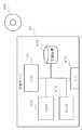
図1は、本発明のおける第1の実施形態に係る情報処理システム10の構成の一例を示すブロック図である。(First embodiment)
FIG. 1 is a block diagram showing an example of the configuration of an
情報処理システム10は、管理サーバ20と、運用サーバ30と、待機サーバ40と、監視サーバ50とを含む。なお、管理サーバ20、運用サーバ30、待機サーバ40、及び、監視サーバ50は、LAN(Local Area Network)やファイバーチャネルのようなネットワーク、又は、装置の内部バスなど一般的な通信路を介して接続している。 The
管理サーバ20は、運用サーバ30と待機サーバ40との業務のための動作の引き継ぎ(フェイルオーバ)を管理する。 The
運用サーバ30は、情報処理ステム10で運用される、図示しないクライアント装置のための業務(サービス)を運用するための情報処理(以下、単に「業務の処理」とも言う)を実行する。 The
待機サーバ40は、運用サーバ30が故障などで動作できなくなった場合、運用サーバ30の業務の処理を引き継ぐ。 When the
監視サーバ50は、運用サーバ30及び待機サーバ40の状態を監視し、管理サーバ20に通知する。 The monitoring
なお、図1は、図面の煩雑さを避けるため、説明に関係する構成を記載したものである。本実施形態の情報処理システム10は、図1の記載に限られるわけではない。例えば、運用サーバ30及び待機サーバ40は、情報処理システム10に2台以上含まれても良い。待機サーバ40が2台以上含まれる場合、管理サーバ20は、運用サーバ30の業務の処理を引き継ぐ待機サーバ40を所定の順番で選択して、フェイルオーバすればよい。例えば、管理サーバ20は、ラウンドロビンのように、順番に待機サーバ40を選択して、フェイルオーバしても良い。さらに、運用サーバ30が論理的に複数のサーバとして動作している場合、管理サーバ20は、複数の待機サーバ40を用いてフェイルオーバしても良い。また、管理サーバ20は、フェイルオーバする運用サーバ30の付加状況を基に、1台の待機サーバ40に複数台の運用サーバ30の業務の処理を引き継がせても良い。 FIG. 1 shows a configuration related to the description in order to avoid complexity of the drawing. The
また、管理サーバ20及び監視サーバ50は、1つのサーバで実現しても良い。あるいは、情報処理システム10は、管理サーバ20又は監視サーバ50を、2台以上含んでも良い。 Further, the
続いて、各サーバの構成について説明する。 Next, the configuration of each server will be described.
まず、管理サーバ20の構成について説明する。 First, the configuration of the
図2は、管理サーバ20の機能的な構成の一例を示すブロック図である。 FIG. 2 is a block diagram illustrating an example of a functional configuration of the
なお、図2は、本実施形態の説明に関連する構成を記載したものである。例えば、表示部など説明に関係しない構成の記載は、省略した。 FIG. 2 describes a configuration related to the description of the present embodiment. For example, description of components that are not related to the description such as a display unit is omitted.
管理サーバ20は、管理処理部210を含む。 The
管理処理部210は、運用サーバ30と待機サーバ40とのフェイルオーバを管理する。そのため、管理処理部210は、運用サーバ30及び待機サーバ40に設定する仮想化情報と、仮想化情報を設定した運用サーバ30又は待機サーバ40に関する情報を含む紐付け情報とを保持(格納)する。 The
管理サーバ20は、監視サーバ50からフェイルオーバの指示を受信すると、紐付け情報を参照して障害が発生した運用サーバ30の仮想化情報を取得する。そして、管理サーバ20は、待機サーバ40に取得した仮想化情報を通知して、フェイルオーバにおける、運用サーバ30から待機サーバ40への切り替えを管理する。なお、本実施形態に用いる仮想化情報に、特に制限は無い。例えば、仮想化情報は、特許文献2に記載されている仮想化情報である。 When receiving the failover instruction from the monitoring
図3は、管理サーバ20のハードウェア構成の一例を示すブロック図である。 FIG. 3 is a block diagram illustrating an example of a hardware configuration of the
なお、図3は、本実施形態の説明に関連する構成を記載したものである。例えば、キーボード、マウス、及び、ディスプレイといった、説明に関係しない構成の記載は、省略した。 FIG. 3 shows a configuration related to the description of the present embodiment. For example, descriptions of components that are not related to the description such as a keyboard, a mouse, and a display are omitted.
管理サーバ20は、CPU220と、ROM(Read Only Memory)222と、RAM(Random Access Memory)224と、記憶装置226と、NIC(ネットワークインターフェース回路又はネットワークインタフェースカード)228とを含む。 The
CPU220は、ROM222又は記憶装置226に含まれるプログラムを読み出して実行し、管理サーバ20としての機能を実行する。CPU220は、プログラムを実行する際、RAM224及び記憶装置226を一時記憶として使用してもよい。また、CPU220は、NIC228を用いて図3には示していないネットワーク(通信路)を介して他の装置又はサーバとデータをやり取りする。なお、CPU220は、NIC228を介して図示しない他の装置からプログラムを取得してもよい。また、CPU220は、コンピュータで読み取り可能な記憶媒体230に含まれるプログラムを、図示しない読み取り装置を用いて読み出して動作しても良い。 The
ROM222は、CPU220が実行するプログラム及び固定データを保持する。 The
RAM224は、CPU220を作業領域としてデータ又はプログラムを一時記憶する。 The
記憶装置226は、CPU220が実行するプログラムやデータを記憶する。また、記憶装置226は、CPU220の作業領域となる場合もある。 The
NIC228は、CPU220と図3には示していないネットワークを介した他の装置とのデータのやり取りを中継する。 The
さらに、管理サーバ20は、個別のサーバとしてではなく、装置の一部の論理構成として実現しても良い。例えば、個々のサーバを1つのブレード(ブレードサーバ)として構成し、抜き差し可能な複数のブレードサーバを搭載できる筐体を備えたブレードサーバ装置が用いられている。このブレードサーバ装置の管理サーバ20の機能は、いずれかのブレードサーバが実現しても良く、ブレードサーバとは別にブレードサーバ装置の筐体に設けられた管理モジュールとして実現しても良い。また、管理サーバ20は、ブレードサーバ装置に接続した別装置のサーバとして実現しても良い。 Furthermore, the
次に、運用サーバ30及び待機サーバ40の構成について説明する。運用サーバ30と待機サーバ40は、同様の機能を備える。そのため、待機サーバ40の構成について説明し、運用サーバ30の構成の詳細な説明は、省略する。なお、運用サーバ30と待機サーバ40は同じ構成のため、本実施形態の説明において、運用サーバ30の構成の符号は、待機サーバ40の構成の符号と同じとする。 Next, the configuration of the
図4は、待機サーバ40の機能的な構成の一例を示すブロック図である。 FIG. 4 is a block diagram illustrating an example of a functional configuration of the
なお、図4は、本実施形態の説明に関連する構成を記載したものである。例えば、表示部など説明に関係しない構成の記載は、省略した。 FIG. 4 shows a configuration related to the description of this embodiment. For example, description of components that are not related to the description such as a display unit is omitted.
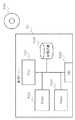
待機サーバ40は、BMC410と、BIOS420と、仮想化情報格納部430と、ハードウェア(HW)情報格納部440と、仮想入出力情報(仮想BIOS情報)格納部450とを含む。 The
BMC410は、待機サーバ40のハードウェアの監視、遠隔操作、ハードウェア・イベントを記録する管理用のコントローラである。BMC410は、待機サーバ40の他のハードウェアとは異なる電源を備え、他のハードウェアの電源をオフした状態でも、電源の供給を受け、動作可能である。そして、BMC410は、待機サーバ40の他のハードウェアの電源のオン(電源を入れる)及びオフ(電源を切る)を制御する。 The
このように、BMC410は、通常、電源が入った(オン)状態である。つまり、待機サーバ40の電源のオン・オフは、BMC410以外のハードウェアの電源のオン・オフとなる。そのため、以下、BMC410を除いた待機サーバ40の他のハードウェア(以下、単に「ハードウェア」と言う)の電源をオン及びオフすることを、待機サーバ40の電源をオン及びオフすると言う場合もある。 Thus, the
また、BMC410は、図4には示していないネットワーク(通信路)を介し、管理サーバ20から、待機サーバ40のハードウェアを仮想化するための仮想化情報を受け取る。さらに、BMC410は、後ほど詳細に説明する本実施形態の待機サーバ40の起動処理を管理する。なお、BMC410は、管理コントローラ又は管理制御部と言うこともできる。 Further, the
BIOS420は、待機サーバ40において、ハードウェアと最も近い、低レベルの入出力を管理および制御する。さらに、BIOS420は、電源オン時などに、ハードウェアの初期化処理、起動時のテスト(POST)、及び、仮想化情報のハードウェアへの設定を制御する。なお、BIOS420は、入出力システム、又は、入出力部と言うこともできる。 The
仮想化情報格納部430は、管理サーバ20から受け取った仮想化情報を格納する。 The virtualization
HW情報格納部440は、出荷時などに設定された待機サーバ40のハードウェアに設定されたハードウェア情報(HW情報)、つまり仮想化を適用しない場合の待機サーバ40のHW情報を格納する。 The HW
仮想化情報格納部430に仮想化情報が格納されている場合、BIOS420は、仮想化情報格納部430に格納されている仮想化情報を待機サーバ40のハードウェアに設定する。 When the virtualization information is stored in the virtualization
一方、仮想化情報格納部430に仮想化情報が格納されていない場合、BIOS420は、HW情報格納部440に格納されているHW情報を待機サーバ40のハードウェアに設定する。 On the other hand, when the virtualization information is not stored in the virtualization
仮想BIOS情報格納部450は、仮想入出力情報(仮想BIOS情報)を格納する。 The virtual BIOS
仮想BIOS情報は、BIOS420の一部又は全部を仮想化する場合に用いる情報である。例えば、仮想BIOS情報は、管理サーバ20から受け取ったブートデバイス情報である。仮想BIOS情報が仮想BIOS情報格納部450に格納されている場合、BIOS420は、仮想BIOS情報を用いて、仮想BIOSとしての機能を実現する。 The virtual BIOS information is information used when a part or all of the
また、仮想BIOS情報格納部450は、高速フラグを格納してもよい。なお、高速フラグは、後ほど詳細に説明する起動動作を指定するフラグである。例えば、高速フラグが格納されている場合、待機サーバ40は、後ほど説明する第1の起動の実施を示す。 The virtual BIOS
図5は、待機サーバ40のハードウェア構成の一例を示すブロック図である。 FIG. 5 is a block diagram illustrating an example of a hardware configuration of the
なお、図5は、本実施形態の説明に関連する構成を記載したものである。例えば、キーボード、マウス、及び、ディスプレイといった、説明に関係しない構成の記載は、省略した。 FIG. 5 describes a configuration related to the description of the present embodiment. For example, descriptions of components that are not related to the description such as a keyboard, a mouse, and a display are omitted.
待機サーバ40は、CPU470と、ROM472と、RAM474と、記憶装置476と、NIC478とを含む。 The
CPU470は、ROM472又は記憶装置476に含まれるプログラムを読み出して実行し、待機サーバ40としての機能を実行する。CPU470は、プログラムを実行する際、RAM474及び記憶装置476を一時記憶として使用する。また、CPU470は、NIC478を介して図5には示していないネットワーク(通信路)に接続した装置やサーバとデータをやり取りする。なお、CPU470は、NIC478を介して図示しない他の装置からプログラムを取得してもよい。また、CPU470は、コンピュータで読み取り可能な記憶媒体480に含まれるプログラムを、図示しない読み取り装置を用いて読み出して動作しても良い。 The
ROM472は、CPU470が実行するプログラム及び固定データを保持する。 The
RAM474は、CPU470を作業領域としてデータ又はプログラムを一時記憶する。 The
記憶装置476は、CPU470が実行するプログラムやデータを記憶する。また、記憶装置476は、CPU470の作業領域となる場合もある。 The
NIC478は、CPU470と図5には示していないネットワーク(通信路)を介した他の装置とのデータのやり取りを中継する。 The
次に、監視サーバ50の構成について説明する。 Next, the configuration of the
図6は、監視サーバ50の機能的な構成の一例を示すブロック図である。 FIG. 6 is a block diagram illustrating an example of a functional configuration of the
なお、図6は、本実施形態の説明に関連する構成を記載したものである。例えば、表示部といった、説明に関係しない構成の記載は、省略した。 FIG. 6 shows a configuration related to the description of the present embodiment. For example, the description of a configuration that is not related to the description, such as a display unit, is omitted.
監視サーバ50は、情報処理システム10の全体を監視する。 The monitoring
そのため、監視サーバ50は、監視処理部510を含む。 Therefore, the monitoring
監視サーバ50の監視処理部510は、運用サーバ30、及び待機サーバ40の動作を監視する。そして、監視処理部510は、運用サーバ30の障害を検出すると、管理サーバ20にフェイルオーバを指示する。なお、監視処理部510は、管理サーバ20を監視しても良い。 The
また、監視サーバ50は、情報処理システム10の管理者などから、情報処理システム10に含まれるいずれのサーバを待機サーバ40とするかの設定、及び、待機サーバ40のフェイルオーバの順番を受け取り保持しても良い。この場合、監視サーバ50は、管理サーバ20に、待機サーバ40の指示、及び、フェイルオーバ時に運用を引き継ぐ待機サーバ40を指定しても良い。 In addition, the monitoring
さらに、監視サーバ50は、各サーバの個別の構成を監視しても良い。例えば、監視サーバ50は、運用サーバ30及び待機サーバ40のBMC410やBIOS420、各サーバのOSやアプリケーションを監視しても良い。 Furthermore, the monitoring
また、監視サーバ50は、情報処理システム10の起動時など所定のタイミングで、管理サーバ20に待機サーバ40の第1の起動を指示する。 In addition, the monitoring
図7は、監視サーバ50のハードウェア構成の一例を示すブロック図である。 FIG. 7 is a block diagram illustrating an example of a hardware configuration of the
なお、図7は、本実施形態の説明に関連する構成を記載したものである。例えば、キーボード、マウス、及び、ディスプレイといった、説明に関係しない構成の記載は、省略した。 FIG. 7 describes a configuration related to the description of the present embodiment. For example, descriptions of components that are not related to the description such as a keyboard, a mouse, and a display are omitted.
監視サーバ50は、CPU520と、ROM522と、RAM524と、記憶装置526と、NIC528とを含む。 The monitoring
CPU520は、ROM522又は記憶装置526に含まれるプログラムを読み出して実行し、監視サーバ50としての機能を実行する。CPU520は、プログラムを実行する際、RAM524及び記憶装置526を一時記憶として使用する。また、CPU520は、NIC528を介して図7には示していないネットワーク(通信路)に接続した装置とデータをやり取りする。なお、CPU520は、NIC528を介して他の装置からプログラムを取得してもよい。また、CPU520は、コンピュータで読み取り可能な記憶媒体530に含まれるプログラムを、図示しない読み取り装置を用いて読み出して動作しても良い。 The
ROM522は、CPU520が実行するプログラム及び固定データを保持する。 The
RAM524は、CPU520を作業領域としてデータ又はプログラムを一時記憶する。 The RAM 524 temporarily stores data or programs using the
記憶装置526は、CPU520が実行するプログラムやデータを記憶する。また、記憶装置526は、CPU520の作業領域となる場合もある。 The
NIC528は、CPU520と図7には示していないネットワーク(通信路)を介した他の装置とのデータのやり取りを中継する。 The NIC 528 relays data exchange between the
なお、既に説明しているが、管理サーバ20と監視サーバ50は、1つのサーバで実現してもよい。 Although already described, the
続いて、情報処理システム10の動作について説明する。 Next, the operation of the
本実施形態に情報処理システム10は、待機サーバ40の起動を2つの段階に分ける。この起動に基づき、情報処理システム10は、待機サーバ40の数が運用サーバ30の数より少ない場合にも対応でき、且つ、フェイルオーバ時の待機サーバ40の起動時間を短くできる。 In this embodiment, the
次に、本実施形態の特徴である待機サーバ40の2つの段階の起動の動作について、それぞれ図面を参照して説明する。 Next, the operation of starting the two stages of the
まず、第1の段階の起動の動作を説明する。 First, the startup operation in the first stage will be described.
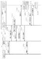
図8は、第1の段階の起動の動作の一例を示すシーケンス図である。 FIG. 8 is a sequence diagram illustrating an example of the activation operation in the first stage.
なお、図8は、動作の説明に関連する構成を記載し、他の構成の記載は省略した。 FIG. 8 shows a configuration related to the description of the operation, and the description of the other configuration is omitted.
待機サーバ40に第1の起動を実行させるため、監視サーバ50は、所定のタイミングで、待機サーバ40の設定及び指示を、管理サーバ20に出力する(1001)。なお、所定のタイミングは、特に制限など無い。ただし、このタイミングは、例えば、情報処理システム10の起動時など、運用サーバ30が動作を開始する前が望ましい。 In order to cause the
管理サーバ20は、指示された待機サーバ40に、一般的な起動ではなく、本実施形態の第1の起動を指示する(1002)。 The
指示を受けた待機サーバ40のBMC410は、第1の起動を指示されたことを格納する(1003)。BMC410は、第1の起動を指示されたことの格納として、例えば、フラグ(高速フラグ)を用意し、仮想BIOS情報格納部450に高速フラグを格納してもよい。なお、本実施形態において、高速フラグの格納は、仮想BIOS情報格納部450に限る必要はない。例えば、BMC410が、高速フラグを格納しても良い。 The
第1の起動の指示(高速フラグ)を格納後、BMC410は、格納完了を管理サーバ20に返す(1004)。 After storing the first activation instruction (high-speed flag), the
格納完了を受けた管理サーバ20は、待機サーバ40のBMC410に電源オンを指示する(1005)。 Upon receiving the storage completion, the
電源オンの指示を受けた待機サーバ40のBMC410は、本実施形態の第1の段階の起動を開始する(1006)。 The
待機サーバ40の第1の段階の起動の以降の動作については、後ほど説明する。 The operation after the start-up of the
第1の段階の起動を開始したBMC410は、管理サーバ20に電源オンの開始を通知する(1007)。 The
電源オンの開始(又は、完了)を受け取った管理サーバ20は、待機サーバ40の電源オンの開始を監視サーバ50に通知する(1008)。 The
なお、管理サーバ20は、第1段階の起動を開始すると待機サーバ40に対しての処理が終了する。そのため、BMC410は、管理サーバ20に電源オンの完了を通知しても良い。電源オンの完了を受け取った管理サーバ20は、監視サーバ50に電源オンの完了を通知する。 Note that the
また、待機サーバ40で電源オンを開始すると、監視サーバ50の処理は、終了する。そのため、管理サーバ20は、電源オンの開始に換えて、電源オンの終了又は設定完了を返しても良い。 Further, when the
待機サーバ40の第1段階の起動の残りの動作について説明する。 The remaining operation of the first activation of the
電源オンの指示を受けたBMC410は、待機サーバ40の電源をオンする。待機サーバ40の電源がオンすると、BIOS420は、ハードウェアの立ち上げ、例えば、ハードウェアの初期化処理(1009)とハードウェアのPOST(1010)とを行う。 Receiving the power-on instruction, the
特許文献2に記載の待機サーバは、この後、通常の起動処理を継続する。 Thereafter, the standby server described in Patent Document 2 continues normal startup processing.
また、特許文献1に記載の待機サーバは、この後、運用サーバに対応した設定(論理区画の確保)を行う。その後、特許文献1に記載の待機サーバは、OSをロードするところで停止する。 In addition, the standby server described in Patent Document 1 performs setting corresponding to the operation server (reserving logical partitions) thereafter. Thereafter, the standby server described in Patent Document 1 stops when the OS is loaded.
本実施形態の待機サーバ40のBIOS420は、次の説明するように、特許文献2及び特許文献1に記載の待機サーバとは異なる動作を行う。 The
ハードウェアの設定が終了すると、BIOS420は、BMC410に第1の起動を指示されているか否かを問い合わせる(1011)。なお、既に説明した高速フラグを用いる場合、BIOS420は、BMC410に高速フラグを格納しているか否かを問い合わせる。 When the hardware setting is completed, the
BMC410は、BIOS420に第1の起動を指示されているか否か(指示状態)を返す(1012)。例えば、高速フラグを用いる場合、BMC410は、高速フラグを格納しているか否かを返す。 The
ここでは、既に説明したとおり第1の起動の指示を受けているため、BMC410は、BIOS420に指示されていることを返す。なお、ここで、第1の起動を指示されていないことを返した場合、BIOS420は、通常の起動を行う。 Here, since the first activation instruction has been received as described above, the
第1の起動を指示されているため、BIOS420は、以降の処理、例えば、ハードウェアに仮想化情報を設定せず、停止状態(スリープなど)を開始する(1013)。本実施形態において、BIOS420が実現するスリープに特に制限はない。例えば、高速フラグを用いる場合、BIOS420は、BMC410が高速フラグの格納をやめるまで、BMC410の高速フラグの格納を定期的に確認(ポーリング)してもよい。あるいは、BIOS420は、ACPI(Advanced Configuration and Power Interface)に定義されたシステムスリープに移行し、BMC410などからスリープ終了の要求を受けるまで、スリープを継続しても良い。 Since the first activation is instructed, the
ここまでの動作で、待機サーバ40の第1の起動は、終了する。 With the operation so far, the first activation of the
つまり、待機サーバ40は、ハードウェアの初期化や初期テストを実施するが、仮想化情報の設定など、運用サーバ30の業務の引き継ぎの際に必要となる情報を設定しないでスリープする。 That is, the
なお、管理サーバ20は、第1の起動指示(1002)と電源オンの指示(1005)を1つの指示としても良い。この場合、BMC410は、第1の起動指示を格納(1003)後、待機サーバ40の電源のオン(1006)を指示する。 The
次に、第2の起動の動作について説明する。 Next, the second activation operation will be described.
第2の起動は、待機サーバ40が第1の起動のスリープ状態に移行後、監視サーバ50が運用サーバ30の障害を検出した場合の動作である。 The second activation is an operation when the
図9は、第2の段階の起動の動作の一例を示すシーケンス図である。 FIG. 9 is a sequence diagram illustrating an example of the activation operation in the second stage.
運用サーバ30の障害(2000)を検出した監視サーバ50は、フェイルオーバを管理サーバ20に要求する(2001)。そのため、監視サーバ50は、管理サーバ20に所定の指示を出力する。なお、情報処理システム10が複数の待機サーバ40を含む場合、管理サーバ20は、監視サーバ50が指定した待機サーバ40を用いてフェイルオーバする。あるいは、管理サーバ20は、所定の規則に従って待機サーバ40を決定してもよい。 The monitoring
フェイルオーバの指示を受けた管理サーバ20は、待機サーバ40がフェイルオーバ可能か否かを確認するため、待機サーバ40に装置状態を要求する(2002)。本実施形態の待機サーバ40は、スリープ状態がフェイルオーバ可能な状態である。そのため、例えば、管理サーバ20は、BMC410に待機サーバ40の電源状態を問い合わせても良い。 Receiving the failover instruction, the
BMC410は、待機サーバ40の装置状態を管理サーバ20に返す(2003)。なお、電源状態を要求されて場合、BMC410は、スリープなど待機サーバ40の電源状態を管理サーバ20に返す。 The
管理サーバ20は、受け取った待機サーバ40の装置状態(例えば、電源状態)を確認する(2004)。待機サーバ40の装置状態がフェイルオーバ可能でない場合、管理サーバ20は、所定の規則の従って再実行(リトライ)するか、監視サーバ50又は図示しない情報処理システム10の保守サーバにフェイルオーバができないことを通知する。なお、管理サーバ20は、リトライとして、例えば、別の待機サーバ40を選択して装置状態の確認する(2002)。 The
待機サーバ40がフェイルオーバ可能な場合、管理サーバ20は、管理サーバ20の管理処理部210が格納する紐付け情報と仮想化情報とを基に、障害を起こした運用サーバ30に設定した仮想化情報を取得する。そして、管理サーバ20は、待機サーバ40に、取得した仮想化情報を送り、待機サーバ40に仮想化情報の設定を指示する(2005)。 When the
仮想化情報を受け取ったBMC410は、仮想化情報を仮想化情報格納部430に格納する(2006)。BMC410は、仮想化情報とともに、管理サーバ20から仮想BIOS情報を受け取っても良い。仮想BIOS情報を受け取ったBMC410は、仮想BIOS情報を仮想BIOS情報格納部450に格納する。 The
情報の格納が終了後、BMC410は、仮想化情報の格納終了を管理サーバ20に通知する(2007)。 After storing the information, the
仮想化情報の格納を受け取った管理サーバ20は、待機サーバ40のBMC410に、待機サーバ40の第2の段階の起動を指示する(2008)。 The
第2の段階の起動の指示を受けたBMC410は、第2の起動を開始する(2009)。 The
具体的には、BMC410は、BIOS420に第2の起動を指示する(2010)。本実施形態に第2の起動の開始の指示は、特に制限はない。例えば、BIOS420が、BMC410の高速フラグをポーリングしている場合、BMC410は、高速フラグを解除しても良い。この場合、BMC410は、具体的な指示をBIOS420に送る必要が無い。このように本実施形態は、必ずしも通知しない場合も含むため、図9の矢印は、破線を用いた。あるいは、BIOS420がACPIのスリープ状態の場合、BMC410は、BIOS420にスリープ解除を指示してもよい。 Specifically, the
この後のBIOS420の動作は、後ほど説明する。 The subsequent operation of the
BIOS420に第2段階の起動を指示後、BMC410は、管理サーバ20に第2段階の起動の開始を通知する(2011)。 After instructing the
起動の開始を受け取った管理サーバ20は、監視サーバ50にフェイルオーバの開始を通知する(2012)。 The
なお、管理サーバ20は、第2段階の起動を開始すると待機サーバ40に対しての処理が終了する。そのため、シーケンス2011において、BMC410は、管理サーバ20に起動の完了を通知しても良い。起動の完了の通知を受けた管理サーバ20は、監視サーバ50にフェイルオーバの完了を通知しても良い。 In addition, the
また、フェイルオーバの開始後、監視サーバ50が待機サーバ40を運用中のサーバとして監視する場合、管理サーバ20は、フェイルオーバの開始の通知に換えて、フェイルオーバの完了を通知しても良い。 In addition, when the
第2の段階の起動の開始の指示を受けたBIOS420は、スリープを終了する。そして、BIOS420は、仮想化情報をハードウェアに設定する。なお、本実施形態のBIOS420の仮想化情報の取得は、特に制限はない。例えば、BIOS420は、仮想化情報格納部430及び仮想BIOS情報格納部450が情報を格納しているかを確認しても良い。本実施形態の説明では、他の例として、BIOS420が、BMC410から仮想化情報と仮想BIOS情報とを取得するとして説明する。 The
BIOS420は、BMC410に仮想化情報(及び仮想BIOS情報)を要求する(2013)。 The
BMC410は、シーケンス2006で格納した、仮想化情報格納部430に格納されている仮想化情報と、仮想BIOS情報格納部450に格納している仮想BIOS情報とを、BIOS420に送る(2014)。 The
BIOS420は、仮想化情報と仮想BIOS情報とを基にハードウェアの仮想化を含む論理的な設定を行い、さらに、仮想BIOS情報を基に仮想BIOSとしての動作を開始する(2015)。 The
ハードウェアの設定を終了後、BIOS420は、OSをロードする(2016)。 After completing the hardware setting, the
そして、待機サーバ40は、運用に必要なアプリケーションの動作を開始し、運用サーバ30の業務の処理を引き継ぐ。 Then, the
ここまで説明した動作で、第2の起動の動作は、終了する。 With the operation described so far, the second activation operation is completed.
この後、待機サーバ40は、運用に必要なアプリケーションの動作を開始する。 Thereafter, the
なお、管理サーバ20は、仮想化情報設定要求(2005)と起動指示(2008)を1つの指示としても良い。この場合、BMC410は、仮想化情報を設定(2006)後、第2の起動を開始する(2009)。 The
本実施形態に係る情報処理システム10は、運用サーバ30より少ない待機サーバ40において、待機サーバ40の起動時間を短縮できる。 The
その理由は、次のとおりである。 The reason is as follows.
本実施形態の待機サーバ40は、障害が発生してフェイルオーバが開始する前にハードウェアの初期化など第1の段階の起動を終了している。そのため、障害が発生してフェイルオーバする場合、待機サーバ40は、仮想化を含む第2の起動を処理すればよい。つまり、待機サーバ40は、第1の段階の起動の時間だけ、フェイルオーバでの起動時間を短くできる。 The
なお、一般的に、サーバの起動において、ハードウェアの仮想化を含む論理的な設定に必要な時間は、ハードウェアの初期化に必要な時間に比べ短い。つまり、待機サーバ40の第2の段階の起動時間は、第1の段階の起動時間に比べ短い。そのため、本実施形態の待機サーバ40は、フェイルオーバで必要となる起動時間を大幅に削減できる。 In general, the time required for logical setting including hardware virtualization in starting the server is shorter than the time required for hardware initialization. That is, the startup time of the second stage of the
さらに、本実施形態の待機サーバ40は、第1の段階の起動後でも、ハードウェアの仮想化を設定していない。そして、待機サーバ40は、第2の段階の起動で、仮想化情報を受け取り、ハードウェアを仮想化する。そのため、待機サーバ40は、いずれの運用サーバ30についてもフェイルオーバに対応できる。つまり、本実施形態の情報処理システム10は、運用サーバ30より少ない台数の待機サーバ40でフェイルオーバを実現できる。 Furthermore, the
以上、実施形態を参照して本願発明を説明したが、本願発明は上記実施形態に限定されるものではない。本願発明の構成や詳細には、本願発明のスコープ内で当業者が理解し得る様々な変更をすることができる。 While the present invention has been described with reference to the embodiments, the present invention is not limited to the above embodiments. Various changes that can be understood by those skilled in the art can be made to the configuration and details of the present invention within the scope of the present invention.
10 情報処理システム
20 管理サーバ
30 運用サーバ
40 待機サーバ
50 監視サーバ
210 管理処理部
220 CPU
222 ROM
224 RAM
226 記憶装置
228 NIC
230 記憶媒体
410 BMC
420 BIOS
430 仮想化情報格納部
440 HW情報格納部
450 仮想BIOS情報格納部
470 CPU
472 ROM
474 RAM
476 記憶装置
478 NIC
480 記憶媒体
510 監視処理部
520 CPU
522 ROM
524 RAM
526 記憶装置
528 NIC
530 記憶媒体DESCRIPTION OF
222 ROM
224 RAM
226
230 Storage medium 410 BMC
420 BIOS
430 Virtualization
472 ROM
474 RAM
476
480
522 ROM
524 RAM
526 storage device 528 NIC
530 storage media
Claims (8)
Translated fromJapanese前記運用サーバの障害時に業務の処理を引き継ぐ待機サーバと、
前記運用サーバと前記待機サーバとの引き継ぎを管理する管理サーバと、
前記運用サーバの障害を検出する監視サーバとを含み、
前記待機サーバは、
前記待機サーバの少なくとも一部のハードウェアを初期化した後に停止する第1の起動と、
前記ハードウェアの仮想化の設定を含む第2の起動とを制御する
入出力手段と、
前記管理サーバからの第1の起動の指示を受けとり、前記入力手段に前記第1の起動を指示し、
前記管理サーバから前記ハードウェアを仮想化するための仮想化情報と、前記第2の起動の指示とを受けとり、前記入出力手段に前記仮想化情報を渡し、前記第2の起動を指示する
管理制御手段と、
を含み、
前記監視サーバは、
所定のタイミングで前記管理サーバに前記待機サーバの前記第1の起動のための指示を出し、
前記運用サーバの障害を検出したときに前記管理サーバに所定の指示を出力し、
前記管理サーバは、
前記監視サーバから前記第1の起動のための指示を受けとり、前記待機サーバに前記第1の起動を指示し、
前記監視サーバから前記所定の指示を受けとり、前記待機サーバに前記仮想化情報と、前記第2の起動の指示を送信する
情報処理システム。An operation server that executes information processing for operating business,
A standby server that takes over business processing in the event of a failure of the operational server;
A management server that manages the takeover between the operation server and the standby server;
A monitoring server that detects a failure of the operational server,
The standby server is
A first start to stop after initializing at least some of the hardware of the standby server;
Input / output means for controlling the second startup including the hardware virtualization setting;
Receiving a first activation instruction from the management server, instructing the first activation to the input means;
Receives virtualization information for virtualizing the hardware and the second activation instruction from the management server, passes the virtualization information to the input / output means, and instructs the second activation Control means;
Including
The monitoring server is
An instruction for the first activation of the standby server is issued to the management server at a predetermined timing,
When a failure of the operation server is detected, a predetermined instruction is output to the management server,
The management server
Receiving an instruction for the first activation from the monitoring server, instructing the standby server to perform the first activation;
An information processing system that receives the predetermined instruction from the monitoring server and transmits the virtualization information and the second activation instruction to the standby server.
前記仮想化情報を格納する仮想化情報格納手段と、
仮想化を適用しないときのハードウェアに関するハードウェア情報を格納するハードウェア情報格納手段と
を含む請求項1に記載の情報処理システム。The standby server is
Virtualization information storage means for storing the virtualization information;
The information processing system according to claim 1, further comprising: hardware information storage means for storing hardware information related to hardware when virtualization is not applied.
前記入出力手段の一部又は全部を仮想化するための情報である仮想入出力情報を格納する仮想入出力情報格納手段
を含む請求項1及び請求項2に記載の情報処理システム。The standby server is
The information processing system according to claim 1, further comprising virtual input / output information storage means for storing virtual input / output information that is information for virtualizing a part or all of the input / output means.
前記仮想化情報と、前記仮想化情報と関係するサーバに関する情報を含む紐付け情報とを含む管理処理手段を
含む請求項2又は請求項3に記載の情報処理システム。The management server
The information processing system according to claim 2 or 3, further comprising management processing means including the virtualization information and association information including information related to a server related to the virtualization information.
前記運用サーバの障害時に業務の処理を引き継ぐ待機サーバと、
前記運用サーバと前記待機サーバとの引き継ぎを管理する管理サーバと、
前記運用サーバの障害を検出する監視サーバとを含み、
前記監視サーバは、
所定のタイミングで前記管理サーバに前記待機サーバの第1の起動のための指示を出力し、
前記運用サーバの障害を検出したときに前記管理サーバに所定の指示を出力し、
前記管理サーバは、
前記監視サーバから前記第1の起動のための指示を受けとり、前記待機サーバに第1の起動を指示し、
前記監視サーバから前記所定の指示を受けとり、前記待機サーバに仮想化情報を送り、第2の起動を指示し、
前記待機サーバは、
前記管理サーバからの前記第1の起動の指示を受けとり、ハードウェアを初期化した後に停止し、
前記管理サーバから前記仮想化情報と前記第2の起動の指示とを受けとり、前記仮想化情報を設定してハードウェアを起動する
情報処理システムの制御方法。An operation server that executes information processing for operating business,
A standby server that takes over business processing in the event of a failure of the operational server;
A management server that manages the takeover between the operation server and the standby server;
A monitoring server that detects a failure of the operational server,
The monitoring server is
Outputting an instruction for first activation of the standby server to the management server at a predetermined timing;
When a failure of the operation server is detected, a predetermined instruction is output to the management server,
The management server
Receiving an instruction for the first activation from the monitoring server, instructing the standby server to perform the first activation,
Receiving the predetermined instruction from the monitoring server, sending virtualization information to the standby server, instructing a second activation;
The standby server is
Receives the first start instruction from the management server, stops after initializing the hardware,
A control method for an information processing system that receives the virtualization information and the second activation instruction from the management server, sets the virtualization information, and activates hardware.
管理サーバからの前記第1の起動の指示を受けとり、前記入力手段に前記第1の起動を指示し、前記管理サーバから前記ハードウェアの仮想化のための仮想化情報と前記第2の起動の指示とを受けとり、前記入出力手段に前記仮想化情報を渡し、前記第2の起動を指示する管理制御手段と
を含む待機サーバ。Input / output means for controlling the first activation that stops after initializing the hardware and the second activation that includes hardware virtualization;
The first activation instruction is received from the management server, the first activation is instructed to the input means, and the virtualization information for hardware virtualization and the second activation instruction are transmitted from the management server. A management server that receives the instruction, passes the virtualization information to the input / output unit, and instructs the second activation.
前記管理サーバからハードウェアの仮想化のための仮想化情報と第2の起動の指示とを受けると前記ハードウェアの仮想化を含む第2の起動を行う
待機サーバの起動方法。Receives the first activation instruction from the management server, performs the first activation to stop after initializing the hardware,
A standby server activation method for performing second activation including virtualization of hardware when receiving virtualization information for hardware virtualization and a second activation instruction from the management server.
前記管理サーバからハードウェアの仮想化するための仮想化情報と第2の起動の指示とを受けとり、ハードウェアの仮想化を含む第2の起動処理と
をコンピュータに実行させる待機サーバのプログラム。A first activation process for receiving a first activation instruction from the management server and stopping after initializing the hardware;
A standby server program that receives virtualization information for hardware virtualization and a second activation instruction from the management server, and causes a computer to execute a second activation process including hardware virtualization.
Priority Applications (1)
| Application Number | Priority Date | Filing Date | Title |
|---|---|---|---|
| JP2012011231AJP5549688B2 (en) | 2012-01-23 | 2012-01-23 | Information processing system and method for controlling information processing system |
Applications Claiming Priority (1)
| Application Number | Priority Date | Filing Date | Title |
|---|---|---|---|
| JP2012011231AJP5549688B2 (en) | 2012-01-23 | 2012-01-23 | Information processing system and method for controlling information processing system |
Publications (2)
| Publication Number | Publication Date |
|---|---|
| JP2013149201Atrue JP2013149201A (en) | 2013-08-01 |
| JP5549688B2 JP5549688B2 (en) | 2014-07-16 |
Family
ID=49046613
Family Applications (1)
| Application Number | Title | Priority Date | Filing Date |
|---|---|---|---|
| JP2012011231AExpired - Fee RelatedJP5549688B2 (en) | 2012-01-23 | 2012-01-23 | Information processing system and method for controlling information processing system |
Country Status (1)
| Country | Link |
|---|---|
| JP (1) | JP5549688B2 (en) |
Cited By (1)
| Publication number | Priority date | Publication date | Assignee | Title |
|---|---|---|---|---|
| CN109992384A (en)* | 2019-03-18 | 2019-07-09 | 北京方鸿智能科技有限公司 | System and method are coordinated in service registration discovery |
Citations (11)
| Publication number | Priority date | Publication date | Assignee | Title |
|---|---|---|---|---|
| JP2007094611A (en)* | 2005-09-28 | 2007-04-12 | Hitachi Ltd | Computer system and boot control method thereof |
| JP2007164305A (en)* | 2005-12-12 | 2007-06-28 | Hitachi Ltd | Boot control method, computer system and processing program therefor |
| JP2008217225A (en)* | 2007-03-01 | 2008-09-18 | Hitachi Ltd | Blade server system |
| JP2008293245A (en)* | 2007-05-24 | 2008-12-04 | Hitachi Ltd | Failover method, computer system, management server and spare server setting method |
| JP2008299509A (en)* | 2007-05-30 | 2008-12-11 | Hitachi Ltd | Virtual computer system |
| JP2009118063A (en)* | 2007-11-05 | 2009-05-28 | Oki Electric Ind Co Ltd | Redundant system, method, program and server |
| JP2009237758A (en)* | 2008-03-26 | 2009-10-15 | Nec Corp | Server system, server management method, and program therefor |
| JP2010134757A (en)* | 2008-12-05 | 2010-06-17 | Hitachi Ltd | Method and device for controlling fail over of server and computer system group |
| JP2010146087A (en)* | 2008-12-16 | 2010-07-01 | Hitachi Ltd | Method of managing system switching computer system |
| JP2011034161A (en)* | 2009-07-30 | 2011-02-17 | Nec Corp | Server system and management method for server system |
| JP2011191854A (en)* | 2010-03-12 | 2011-09-29 | Hitachi Ltd | Computer system, control method of computer system, and program |
- 2012
- 2012-01-23JPJP2012011231Apatent/JP5549688B2/ennot_activeExpired - Fee Related
Patent Citations (11)
| Publication number | Priority date | Publication date | Assignee | Title |
|---|---|---|---|---|
| JP2007094611A (en)* | 2005-09-28 | 2007-04-12 | Hitachi Ltd | Computer system and boot control method thereof |
| JP2007164305A (en)* | 2005-12-12 | 2007-06-28 | Hitachi Ltd | Boot control method, computer system and processing program therefor |
| JP2008217225A (en)* | 2007-03-01 | 2008-09-18 | Hitachi Ltd | Blade server system |
| JP2008293245A (en)* | 2007-05-24 | 2008-12-04 | Hitachi Ltd | Failover method, computer system, management server and spare server setting method |
| JP2008299509A (en)* | 2007-05-30 | 2008-12-11 | Hitachi Ltd | Virtual computer system |
| JP2009118063A (en)* | 2007-11-05 | 2009-05-28 | Oki Electric Ind Co Ltd | Redundant system, method, program and server |
| JP2009237758A (en)* | 2008-03-26 | 2009-10-15 | Nec Corp | Server system, server management method, and program therefor |
| JP2010134757A (en)* | 2008-12-05 | 2010-06-17 | Hitachi Ltd | Method and device for controlling fail over of server and computer system group |
| JP2010146087A (en)* | 2008-12-16 | 2010-07-01 | Hitachi Ltd | Method of managing system switching computer system |
| JP2011034161A (en)* | 2009-07-30 | 2011-02-17 | Nec Corp | Server system and management method for server system |
| JP2011191854A (en)* | 2010-03-12 | 2011-09-29 | Hitachi Ltd | Computer system, control method of computer system, and program |
Cited By (2)
| Publication number | Priority date | Publication date | Assignee | Title |
|---|---|---|---|---|
| CN109992384A (en)* | 2019-03-18 | 2019-07-09 | 北京方鸿智能科技有限公司 | System and method are coordinated in service registration discovery |
| CN109992384B (en)* | 2019-03-18 | 2020-07-14 | 北京方鸿智能科技有限公司 | Service registration discovery coordination system and method thereof |
Also Published As
| Publication number | Publication date |
|---|---|
| JP5549688B2 (en) | 2014-07-16 |
Similar Documents
| Publication | Publication Date | Title |
|---|---|---|
| US7802127B2 (en) | Method and computer system for failover | |
| JP4572250B2 (en) | Computer switching method, computer switching program, and computer system | |
| US7953831B2 (en) | Method for setting up failure recovery environment | |
| JP4842210B2 (en) | Failover method, computer system, management server and spare server setting method | |
| JP5068056B2 (en) | Failure recovery method, computer system and management server | |
| US9026858B2 (en) | Testing server, information processing system, and testing method | |
| US10789141B2 (en) | Information processing device and information processing method | |
| CN103618627B (en) | A kind of manage the method for virtual machine, Apparatus and system | |
| JP5770284B2 (en) | I/O switch control method, virtual computer control method, and computer system | |
| EP2648095B1 (en) | System and method for controlling the booting of a computer | |
| EP2835716A1 (en) | Information processing device and virtual machine control method | |
| US8074098B2 (en) | Control method for information processing system, information processing system, and program | |
| JP5549688B2 (en) | Information processing system and method for controlling information processing system | |
| JP6148039B2 (en) | Information processing apparatus, BMC switching method, BMC switching program | |
| JP5266347B2 (en) | Takeover method, computer system and management server | |
| US20220357976A1 (en) | Information processing apparatus, information processing method, and computer-readable recording medium storing information processing program | |
| WO2014041625A1 (en) | Information processing device and power control method | |
| US9195554B2 (en) | Information processing apparatus and maintenance method of an information processing apparatus | |
| JP6822706B1 (en) | Cluster system, server equipment, takeover method, and program | |
| CN102480386A (en) | Server cabinet system and its starting method, server starting method | |
| WO2013171832A1 (en) | Information processing device, information processing method and program | |
| JP2011258233A (en) | Fail-over method and computer system thereof |
Legal Events
| Date | Code | Title | Description |
|---|---|---|---|
| A131 | Notification of reasons for refusal | Free format text:JAPANESE INTERMEDIATE CODE: A131 Effective date:20130528 | |
| A521 | Request for written amendment filed | Free format text:JAPANESE INTERMEDIATE CODE: A523 Effective date:20130704 | |
| A131 | Notification of reasons for refusal | Free format text:JAPANESE INTERMEDIATE CODE: A131 Effective date:20140212 | |
| A521 | Request for written amendment filed | Free format text:JAPANESE INTERMEDIATE CODE: A523 Effective date:20140404 | |
| TRDD | Decision of grant or rejection written | ||
| A01 | Written decision to grant a patent or to grant a registration (utility model) | Free format text:JAPANESE INTERMEDIATE CODE: A01 Effective date:20140422 | |
| A61 | First payment of annual fees (during grant procedure) | Free format text:JAPANESE INTERMEDIATE CODE: A61 Effective date:20140505 | |
| R150 | Certificate of patent or registration of utility model | Ref document number:5549688 Country of ref document:JP Free format text:JAPANESE INTERMEDIATE CODE: R150 | |
| LAPS | Cancellation because of no payment of annual fees |