JP2013145949A - Projection system, and alignment adjusting method for superposed image - Google Patents
Projection system, and alignment adjusting method for superposed imageDownload PDFInfo
- Publication number
- JP2013145949A JP2013145949AJP2012005181AJP2012005181AJP2013145949AJP 2013145949 AJP2013145949 AJP 2013145949AJP 2012005181 AJP2012005181 AJP 2012005181AJP 2012005181 AJP2012005181 AJP 2012005181AJP 2013145949 AJP2013145949 AJP 2013145949A
- Authority
- JP
- Japan
- Prior art keywords
- test pattern
- image
- projection
- straight line
- corner
- Prior art date
- Legal status (The legal status is an assumption and is not a legal conclusion. Google has not performed a legal analysis and makes no representation as to the accuracy of the status listed.)
- Pending
Links
- 238000000034methodMethods0.000titleclaimsdescription42
- 238000012360testing methodMethods0.000claimsabstractdescription257
- 238000003384imaging methodMethods0.000claimsdescription82
- 238000001514detection methodMethods0.000claimsdescription20
- 230000002093peripheral effectEffects0.000claimsdescription6
- 238000012545processingMethods0.000abstractdescription34
- 238000006073displacement reactionMethods0.000abstractdescription3
- 230000008569processEffects0.000description28
- 238000010586diagramMethods0.000description10
- 230000007246mechanismEffects0.000description5
- 230000004044responseEffects0.000description4
- 238000004891communicationMethods0.000description3
- 238000005516engineering processMethods0.000description3
- 230000004048modificationEffects0.000description3
- 238000012986modificationMethods0.000description3
- 238000012790confirmationMethods0.000description2
- 238000010191image analysisMethods0.000description2
- 230000009467reductionEffects0.000description2
- 230000008859changeEffects0.000description1
- 230000006870functionEffects0.000description1
- 239000011521glassSubstances0.000description1
- 230000006872improvementEffects0.000description1
- 238000009434installationMethods0.000description1
- 238000012216screeningMethods0.000description1
Images


Landscapes
- Projection Apparatus (AREA)
- Transforming Electric Information Into Light Information (AREA)
Abstract
Description
Translated fromJapanese本技術は、投影システム、および重畳画像の画合わせの調整方法に関する。 The present technology relates to a projection system and a method for adjusting image alignment of a superimposed image.
立体画像の表示や、高精細な画像の表示をおこなうために、複数の投影装置が投影する画像を、1つのスクリーン上に重ね合わせることがおこなわれている。たとえば、近年、映画館等で立体画像を観察可能な映画が広く上映されるようになっている。このような映画館では、左眼観察用の画像と、右眼観察用の画像とを1つのスクリーン上に表示している。観客は、立体視用のメガネを装着して、1つのスクリーン上に表示された画像を、左眼観察用の画像と右眼観察用の画像とに分離し、左眼用画像を左眼で、右眼用画像を右眼で観察している。 In order to display a stereoscopic image and a high-definition image, images projected by a plurality of projection devices are superimposed on one screen. For example, in recent years, movies that can observe stereoscopic images have been widely screened in movie theaters and the like. In such a movie theater, an image for left eye observation and an image for right eye observation are displayed on one screen. The audience wears glasses for stereoscopic viewing, separates the image displayed on one screen into an image for left eye observation and an image for right eye observation, and the left eye image with the left eye. The right eye image is observed with the right eye.
このような、1つのスクリーン上への複数の画像の重ね合わせは、それぞれの画像のズーム量や、投影位置の精度が悪いと、映像の品質が低下する。1つのスクリーン上に重ね合わせて高精細な画像の表示をおこなう場合であっても、画像の重ね合わせの精度の低下が、映像の品質を低下させることについては同様である。 In such superposition of a plurality of images on one screen, the quality of the video is deteriorated if the zoom amount of each image or the accuracy of the projection position is poor. Even in the case of displaying a high-definition image superimposed on one screen, the reduction in the image overlay accuracy is the same as the reduction in the image overlay accuracy.
また、近年の映画館は、客を入れ替えて異なる作品を上映するプログラムを組む例があり、その場合、スクリーンのアスペクト比を変更することがある。スクリーンのアスペクト比の変更は、投影装置のズーム量の変更によっておこなわれ、機械要素である投射レンズの駆動を伴う。 In recent movie theaters, there is an example of creating a program for screening different works by changing customers, in which case the aspect ratio of the screen may be changed. The screen aspect ratio is changed by changing the zoom amount of the projection apparatus, and is accompanied by driving of a projection lens which is a mechanical element.
そのため、映画館は、スクリーンのアスペクト比の変更の都度、画合わせの調整をおこなうことが求められる場合がある。こうした画像の重ね合わせの調整方法については、いくつかの提案がなされている。 For this reason, the movie theater may be required to adjust the image alignment every time the aspect ratio of the screen is changed. Several proposals have been made for a method for adjusting the overlay of images.
しかしながら、画像の重ね合わせの際の調整方法の多くは、キャプチャ用のカメラを用いて、スクリーン全体をキャプチャしたうえで、信号処理により、投影装置が投影する画像の画合わせをおこなうのが一般的である。 However, in many of the adjustment methods when superimposing images, it is common to use a capture camera to capture the entire screen and then perform image alignment of the image projected by the projection device by signal processing. It is.
このとき、キャプチャ用のカメラは、投影する画像よりも高い解像度が求められるなどして、画合わせの調整システムを高コスト化している。また、画像の重ね合わせの際の調整方法の多くは、画合わせをおこなうための信号処理が複雑であり、簡素化が求められている。 At this time, the capture camera is required to have a higher resolution than the image to be projected, and the cost of the image matching adjustment system is increased. Further, many of the adjustment methods for superimposing images are complicated in signal processing for performing image matching, and are required to be simplified.
本技術は、このような点に鑑みてなされたものであり、高い解像度を必要としないキャプチャ用カメラを用いることが可能であって、重畳画像の画合わせの調整を、簡素な信号処理によって精度よくおこなうことが可能な投影システム、および重畳画像の画合わせの調整方法の提供を目的とする。 The present technology has been made in view of such a point, and can use a capture camera that does not require high resolution, and can perform adjustment of superimposed image alignment with simple signal processing. It is an object of the present invention to provide a projection system that can be performed well and a method for adjusting the alignment of superimposed images.
上記課題を解決するために、投影システムは、第1の投影装置と、第2の投影装置と、第1の撮影装置と、第2の撮影装置と、制御装置と、を備える。第1の投影装置は、第1の画像を投影する。第2の投影装置は、第2の画像を投影する。第1の撮影装置は、第1の画像と第2の画像が重畳した重畳画像の第1の隅部を撮影する。第2の撮影装置は、重畳画像の第2の隅部を撮影する。制御装置は、ズーム量制御部と、投影位置制御部と、を備え、第1の隅部の撮影画像と第2の隅部の撮影画像とから、第1の画像と第2の画像の画合わせを制御する。 In order to solve the above problems, a projection system includes a first projection device, a second projection device, a first imaging device, a second imaging device, and a control device. The first projection device projects the first image. The second projection device projects the second image. The first imaging device captures a first corner of the superimposed image in which the first image and the second image are superimposed. The second imaging device captures the second corner of the superimposed image. The control device includes a zoom amount control unit and a projection position control unit, and images of the first image and the second image are obtained from the captured image of the first corner and the captured image of the second corner. Control alignment.
ズーム量制御部は、第1の隅部の撮影画像と第2の隅部の撮影画像とから第1の投影装置のレンズのズーム量と第2の投影装置のレンズのズーム量とのズーム誤差を検出し、ズーム誤差にもとづくズームの調整量を、第1の投影装置と第2の投影装置とに指示する。投影位置制御部は、ズーム量調整後の第1の隅部の撮影画像と、ズーム量調整後の第2の隅部の撮影画像とから、第1の投影装置の投影位置と第2の投影装置の投影位置との投影位置誤差を検出し、投影位置誤差にもとづく投影位置の調整量を、第1の投影装置と第2の投影装置とに指示する。 The zoom amount control unit is configured to detect a zoom error between a zoom amount of the lens of the first projection device and a zoom amount of the lens of the second projection device from the captured image of the first corner and the captured image of the second corner. And the zoom adjustment amount based on the zoom error is instructed to the first projection apparatus and the second projection apparatus. The projection position control unit is configured to calculate the projection position of the first projection device and the second projection from the captured image of the first corner after adjusting the zoom amount and the captured image of the second corner after adjusting the zoom amount. A projection position error with respect to the projection position of the apparatus is detected, and an adjustment amount of the projection position based on the projection position error is instructed to the first projection apparatus and the second projection apparatus.
また、上記課題を解決するために、投影システムは、第1の投影装置と、第2の投影装置と、第1の撮影装置と、第2の撮影装置と、第3の撮影装置と、制御装置と、を備える。第1の投影装置は、第1の画像を投影する。第2の投影装置は、第2の画像を投影する。第1の撮影装置は、第1の画像と第2の画像が重畳した重畳画像の第1の隅部を撮影する。第2の撮影装置は、重畳画像の第2の隅部を撮影する。第3の撮影装置は、重畳画像の中間部を撮影する。制御装置は、ズーム量制御部と、投影位置制御部と、を備え、第1の隅部の撮影画像と第2の隅部の撮影画像と中間部の撮影画像とから、第1の画像と第2の画像の画合わせを制御する。 In order to solve the above problem, a projection system includes a first projection device, a second projection device, a first imaging device, a second imaging device, a third imaging device, and a control. An apparatus. The first projection device projects the first image. The second projection device projects the second image. The first imaging device captures a first corner of the superimposed image in which the first image and the second image are superimposed. The second imaging device captures the second corner of the superimposed image. The third imaging device captures an intermediate portion of the superimposed image. The control device includes a zoom amount control unit and a projection position control unit, and the first image is obtained from the captured image of the first corner, the captured image of the second corner, and the captured image of the intermediate portion. Controls the alignment of the second image.
ズーム量制御部は、第1の隅部の撮影画像と第2の隅部の撮影画像とから第1の投影装置のレンズのズーム量と第2の投影装置のレンズのズーム量とのズーム誤差を検出し、ズーム誤差にもとづくズームの調整量を、第1の投影装置と第2の投影装置とに指示する。投影位置制御部は、ズーム量調整後の中間部の撮影画像とから、第1の投影装置の投影位置と第2の投影装置の投影位置との投影位置誤差を検出し、投影位置誤差にもとづく投影位置の調整量を、第1の投影装置と第2の投影装置とに指示する。 The zoom amount control unit is configured to detect a zoom error between a zoom amount of the lens of the first projection device and a zoom amount of the lens of the second projection device from the captured image of the first corner and the captured image of the second corner. And the zoom adjustment amount based on the zoom error is instructed to the first projection apparatus and the second projection apparatus. The projection position control unit detects a projection position error between the projection position of the first projection apparatus and the projection position of the second projection apparatus from the captured image of the intermediate part after adjusting the zoom amount, and based on the projection position error. The adjustment amount of the projection position is instructed to the first projection device and the second projection device.
また、上記課題を解決するために、第1の投影装置が投影する第1の画像と、第2の投影装置が投影する第2の画像との重畳画像の画合わせの調整方法は、重畳画像の第1の隅部を撮影するステップと、重畳画像の第2の隅部を撮影するステップと、第1の隅部の撮影画像と第2の隅部の撮影画像とから第1の投影装置のレンズのズーム量と第2の投影装置のレンズのズーム量とのズーム誤差を検出するステップと、ズーム誤差にしたがった第1の投影装置のレンズのズーム量の調整と、ズーム誤差にしたがった第2の投影装置のレンズのズーム量の調整のうち、少なくともいずれか一方を実行するステップと、ズーム量調整後の第1の隅部の撮影画像と、ズーム量調整後の第2の隅部の撮影画像とから、第1の投影装置の投影位置と第2の投影装置の投影位置との投影位置誤差を検出するステップと、投影位置誤差にしたがった第1の投影装置の投影位置の調整と、投影位置誤差にしたがった第2の投影装置の投影位置の調整のうち、少なくともいずれか一方を実行するステップと、を含む。 In addition, in order to solve the above-described problem, the adjustment method of the superposition image of the first image projected by the first projection device and the second image projected by the second projection device is a superimposed image. A first projection device based on a step of photographing the first corner, a step of photographing the second corner of the superimposed image, a photographed image of the first corner, and a photographed image of the second corner. Detecting a zoom error between the zoom amount of the first lens and the zoom amount of the lens of the second projector, adjusting the zoom amount of the lens of the first projector according to the zoom error, and following the zoom error. A step of executing at least one of the adjustments of the zoom amount of the lens of the second projection device, a captured image of the first corner after adjustment of the zoom amount, and a second corner after adjustment of the zoom amount; From the captured image, the projection position of the first projection device and the second Detecting a projection position error with respect to the projection position of the shadow apparatus; adjusting the projection position of the first projection apparatus according to the projection position error; and adjusting the projection position of the second projection apparatus according to the projection position error And executing at least one of them.
上記の投影システム、および重畳画像の画合わせの調整方法によれば、高い解像度を必要としないキャプチャ用カメラを用いることが可能であって、重畳画像の画合わせの調整を、簡素な信号処理によって精度よくおこなうことができる。 According to the projection system and the adjustment method of the superimposition image matching, it is possible to use a capture camera that does not require high resolution, and the superimposition image adjustment can be adjusted by simple signal processing. It can be done accurately.
以下、本技術の実施の形態を図面を参照して詳細に説明する。 Hereinafter, embodiments of the present technology will be described in detail with reference to the drawings.
[第1の実施形態]
まず、第1の実施形態の投影システムについて図1を用いて説明する。図1は、第1の実施形態の投影システムの構成例を示す図である。[First Embodiment]
First, the projection system of the first embodiment will be described with reference to FIG. FIG. 1 is a diagram illustrating a configuration example of a projection system according to the first embodiment.
投影システム1は、1つのスクリーン上に2つの画像を重ね合わせて投影する際に、重ね合わせた2つの画像(重畳画像)の画合わせの調整をおこなう。投影システム1は、たとえば、スクリーンに映像を上映する映画館などで用いられる。 The projection system 1 adjusts the image alignment of two superimposed images (superimposed images) when projecting two images superimposed on one screen. The projection system 1 is used in, for example, a movie theater that displays an image on a screen.
1つのスクリーン上に重ね合わせて投影される2つの画像は、重ね合わせて1つの画像として表示されるものであればよい。たとえば、重ね合わせて投影される2つの画像は、立体画像を表示する場合の左眼用画像と右眼用画像である。また、重ね合わせて投影される2つの画像は、合成することで解像度を向上させる画像や、映像と字幕、あるいは地図と文字など異なるコンテンツを表示する画像などであってもよい。 The two images that are superimposed and projected on one screen may be any image that is displayed as a single image in a superimposed manner. For example, the two images projected in a superimposed manner are a left-eye image and a right-eye image when a stereoscopic image is displayed. In addition, the two images projected in a superimposed manner may be an image that improves resolution by being combined, an image that displays different contents such as video and subtitles, or a map and characters.
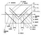
投影システム1は、制御装置2と、プロジェクタ(第1の投影装置)5と、プロジェクタ(第2の投影装置)8と、撮影装置(第1の撮影装置)15と、撮影装置(第2の撮影装置)16と、を備える。 The projection system 1 includes a
プロジェクタ5は、スクリーンに投影画像(第1の画像)11を投影する投影装置である。プロジェクタ8は、スクリーンに投影画像(第2の画像)12を投影する投影装置である。投影画像11と投影画像12は、1つのスクリーン上に投影される。 The
プロジェクタ5は、投影画像11に複数のテストパタンを含めて投影することができる。投影画像11に含まれるテストパタンは、投影画像11の隅部(四辺および四角を含む画像周縁部)に表示される。たとえば、投影画像11に含まれるテストパタンは、投影画像11の左下隅部(第1の隅部)にある撮影範囲13と、投影画像11の右下隅部(第2の隅部)にある撮影範囲14に相当する位置にそれぞれ表示される。 The
プロジェクタ8は、投影画像12に複数のテストパタンを含めて投影することができる。投影画像12に含まれるテストパタンは、投影画像12の隅部(四辺および四角を含む画像周縁部)に表示される。たとえば、投影画像12に含まれるテストパタンは、投影画像12の左下隅部にある撮影範囲13と、投影画像12の右下隅部にある撮影範囲14に相当する位置にそれぞれ表示される。 The
投影画像11に含まれるテストパタンと、投影画像12に含まれるテストパタンは、投影画像11と投影画像12の両方の、あるいは投影画像11と投影画像12のいずれか一方のズーム調整と投影位置調整をおこなう際の調整量の決定に用いることができる。テストパタンの詳細については、図2から図4を用いて後で説明する。 The test pattern included in the projection image 11 and the test pattern included in the projection image 12 are the zoom adjustment and the projection position adjustment of both the projection image 11 and the projection image 12 or one of the projection image 11 and the projection image 12. It can be used to determine the amount of adjustment when performing. Details of the test pattern will be described later with reference to FIGS.
撮影装置15は、投影画像11と投影画像12が重畳して投影される領域を含む撮影範囲13を撮影する撮影装置である。撮影装置16は、投影画像11と投影画像12が重畳して投影される領域を含む撮影範囲14を撮影する撮影装置である。撮影装置15,16は、投影画像11および投影画像12の隅部のうち、それぞれ異なる隅部を撮影範囲とする。たとえば、撮影装置15は、投影画像11と投影画像12の左下隅部に位置する撮影範囲13を撮影範囲とし、撮影装置16は、投影画像11と投影画像12の右下隅部に位置する撮影範囲14を撮影範囲とする。 The
これにより、撮影装置15は、投影画像11に含まれるテストパタンと、投影画像12に含まれるテストパタンとを撮影範囲13に含む。撮影装置16は、投影画像11に含まれるテストパタンと、投影画像12に含まれるテストパタンとを撮影範囲14に含む。 Thereby, the
撮影装置15,16は、それぞれ、撮影した画像(画像情報)を制御装置2に出力する。 The photographing
なお、撮影装置15,16は、投影画像11,12のうちの一部を撮影範囲とし、全部を撮影範囲としないことで、映像コンテンツ(たとえば、映画)全体のキャプチャをおこなうことができないようにしている。撮影装置15,16は、投影画像11,12の全部を撮影範囲としないために、投影システム1は、スクリーンに近接した位置に撮影装置15,16を設置することができる。また、投影システム1は、撮影装置15,16の解像度をプロジェクタ5,8よりも低くすることで、撮影装置15,16の設置位置の変更があっても投影画像11,12の全部を撮影範囲とする高画質なキャプチャを防止することができる。これにより、投影システム1は、撮影装置15,16が映像コンテンツの複製機器として機能することを防止している。 Note that the
プロジェクタ5は、ズーム調整部6と投影位置調整部7を備える。ズーム調整部6は、制御装置2から指示される調整情報にもとづいて、図示しない投射レンズを駆動して投影画像11のズーム調整をおこなう。投影位置調整部7は、制御装置2から指示される調整情報にもとづいて、信号処理により投影画像11の画像中心位置の調整をおこなう。 The
プロジェクタ8は、ズーム調整部9と投影位置調整部10を備える。ズーム調整部9は、制御装置2から指示される調整情報にもとづいて、図示しない投射レンズを駆動して投影画像12のズーム調整をおこなう。投影位置調整部10は、制御装置2から指示される調整情報にもとづいて、信号処理により投影画像12の画像中心位置(画像投影位置)の調整をおこなう。 The
調整情報は、投射レンズのズーム位置を調整するための情報と、投影画像の画像中心位置を調整するための情報を含む。投射レンズのズーム位置を調整するための情報は、たとえば、ズーム位置を指定する情報や、現在のズーム位置からの調整量を指定する情報などがある。投影画像の画像中心位置を調整するための情報は、たとえば、画像中心位置を指定する情報や、現在の画像中心位置からの調整量を指定する情報などがある。なお、画像中心位置の調整は、投影画像の水平位置の調整と、投影画像の垂直位置の調整とによりおこなうことができる。 The adjustment information includes information for adjusting the zoom position of the projection lens and information for adjusting the image center position of the projection image. Information for adjusting the zoom position of the projection lens includes, for example, information for specifying the zoom position and information for specifying the adjustment amount from the current zoom position. Information for adjusting the image center position of the projected image includes, for example, information for specifying the image center position, information for specifying an adjustment amount from the current image center position, and the like. Note that the adjustment of the image center position can be performed by adjusting the horizontal position of the projection image and adjusting the vertical position of the projection image.
制御装置2は、投影画像11と投影画像12の画合わせを制御する。制御装置2は、撮影装置15から入力する画像情報と、撮影装置16から入力する画像情報とから、調整情報を決定する。制御装置2は、調整情報にもとづいて、プロジェクタ5,8の両方、あるいはいずれか一方に、投射レンズのズーム位置の調整の指示と、投影画像の画像中心位置の調整の指示をおこなう。 The
制御装置2は、ズーム量制御部3と投影位置制御部4を備える。ズーム量制御部3は、撮影範囲13の撮影画像と撮影範囲14の撮影画像とから、プロジェクタ5の投射レンズのズーム量とプロジェクタ8の投射レンズのズーム量との誤差(ズーム誤差)を検出する。ズーム量制御部3は、検出したズーム誤差にもとづいて、プロジェクタ5とプロジェクタ8の少なくともいずれか一方に対して、投射レンズのズーム量の調整の指示をおこなう。 The
投影位置制御部4は、ズーム量調整後の撮影範囲13の撮影画像と、ズーム量調整後の撮影範囲14の撮影画像とから、プロジェクタ5の投影位置とプロジェクタ8の投影位置との誤差(投影位置誤差)を検出する。投影位置制御部4は、検出した投影位置誤差にもとづいて、プロジェクタ5とプロジェクタ8の少なくともいずれか一方に対して、投影位置誤差の調整の指示をおこなう。 The projection position control unit 4 calculates an error (projection) between the projection position of the
このように、投影システム1は、投影位置誤差の調整の前に、投影画像11の大きさと投影画像12の大きさの調整(ズーム調整)をおこなうことで、投射レンズを駆動した際に生ずるメカ機構の誤差を収束させる。これにより、投影システム1は、投影位置誤差の調整の後に投射レンズを駆動することで、再度、投影位置誤差が生じて、調整が収束しなくなることを防止している。 As described above, the projection system 1 adjusts the size of the projection image 11 and the size of the projection image 12 (zoom adjustment) before adjusting the projection position error, thereby generating a mechanism generated when the projection lens is driven. The mechanism error is converged. Thereby, the projection system 1 prevents the adjustment from being converged again by causing the projection position error again by driving the projection lens after the adjustment of the projection position error.
そして、投影システム1は、投影画像11の大きさと投影画像12の大きさの調整後に、投影位置誤差の調整をおこなうという2段階調整をおこなうことで、画合わせを効率的におこなうことを可能にしている。 Then, the projection system 1 can perform image matching efficiently by performing two-stage adjustment of adjusting the projection position error after adjusting the size of the projection image 11 and the size of the projection image 12. ing.
なお、隅部は、中央部から離れた目立たない部分(片隅)となる周縁部を含むものである。隅部を投影領域が矩形である場合の四隅とすることで、中央部と隅部の距離を大きくとることができ、調整量(レンズのズームの調整量、投影位置の調整量)検出の精度向上に寄与する。 In addition, a corner part contains the peripheral part used as the non-conspicuous part (one corner) away from the center part. By setting the corners to the four corners when the projection area is rectangular, the distance between the center and the corner can be increased, and the adjustment amount (lens zoom adjustment amount, projection position adjustment amount) detection accuracy Contributes to improvement.
次に、第1の実施形態の重畳画像におけるテストパタンと、重畳画像の撮影範囲、その撮影範囲における撮影画像について図2から図4を用いて説明する。図2は、第1の実施形態の重畳画像におけるテストパタンの表示例と、撮影画像の一例を示す図である。図3、図4は、第1の実施形態のテストパタンの撮影画像の一例を示す図である。 Next, the test pattern in the superimposed image, the shooting range of the superimposed image, and the shot image in the shooting range of the first embodiment will be described with reference to FIGS. FIG. 2 is a diagram illustrating a display example of a test pattern in a superimposed image and an example of a captured image according to the first embodiment. 3 and 4 are diagrams illustrating an example of a captured image of the test pattern according to the first embodiment.
重畳画像20は、投影画像11と投影画像12を重畳(画合わせ)した画像である。ここで、図面の上下方向を重畳画像20の垂直方向とし、図面の左右方向を重畳画像20の水平方向とする。 The superimposed image 20 is an image in which the projection image 11 and the projection image 12 are superimposed (image matching). Here, the vertical direction of the drawing is the vertical direction of the superimposed image 20, and the horizontal direction of the drawing is the horizontal direction of the superimposed image 20.
重畳画像20の左下隅部には、投影画像11のテストパタン(第1のテストパタン)23と、投影画像12のテストパタン(第2のテストパタン)22が位置する。テストパタン23は、水平線からなる直線部38と垂直線からなる直線部30とが接続点35で接続したL字状である。テストパタン23は、テストパタン23の角部(接続点35)の向きと、重畳画像20の対応する角部の向きとを同じにして配置される。言い換えれば、テストパタン23は、重畳画像20の底辺であって、重畳画像20の周縁を形成する重畳画像底辺25の近傍に直線部38が配置され、重畳画像20の左辺であって、重畳画像20の周縁を形成する重畳画像左辺24の近傍に直線部30が配置される。 A test pattern (first test pattern) 23 of the projection image 11 and a test pattern (second test pattern) 22 of the projection image 12 are located at the lower left corner of the superimposed image 20. The
テストパタン22は、水平線からなる直線部39と垂直線からなる直線部31とが接続点34で接続したL字状である。テストパタン22は、テストパタン22の角部(接続点34)の向きと、重畳画像20の対応する角部の向きとを同じにして配置される。言い換えれば、テストパタン22は、重畳画像20の底辺であって、重畳画像20の周縁を形成する重畳画像底辺25の近傍に直線部39が配置され、重畳画像20の左辺であって、重畳画像20の周縁を形成する重畳画像左辺24の近傍に直線部31が配置される。 The
重畳画像20の右下隅部には、投影画像11のテストパタン(第3のテストパタン)27と、投影画像12のテストパタン(第4のテストパタン)28が位置する。テストパタン27は、水平線からなる直線部41と垂直線からなる直線部49とが接続点46で接続したL字状である。テストパタン27は、テストパタン27の角部(接続点46)の向きと、重畳画像20の対応する角部の向きとを同じにして配置される。言い換えれば、テストパタン27は、重畳画像20の底辺であって、重畳画像20の周縁を形成する重畳画像底辺25の近傍に直線部41が配置され、重畳画像20の右辺であって、重畳画像20の周縁を形成する重畳画像右辺26の近傍に直線部49が配置される。 A test pattern (third test pattern) 27 of the projection image 11 and a test pattern (fourth test pattern) 28 of the projection image 12 are located at the lower right corner of the superimposed image 20. The
テストパタン28は、水平線からなる直線部42と垂直線からなる直線部50とが接続点45で接続したL字状である。テストパタン28は、テストパタン28の角部(接続点45)の向きと、重畳画像20の対応する角部の向きとを同じにして配置される。言い換えれば、テストパタン28は、重畳画像20の底辺であって、重畳画像20の周縁を形成する重畳画像底辺25の近傍に直線部42が配置され、重畳画像20の右辺であって、重畳画像20の周縁を形成する重畳画像右辺26の近傍に直線部50が配置される。 The
なお、テストパタン22とテストパタン23は、画像解析により識別可能な表示態様となっている。画像解析により識別可能な表示態様は、色、形、形状、大きさによる区別の他、文字や記号などを含むものであってもよい。たとえば、テストパタン22とテストパタン23、あるいはテストパタン27とテストパタン28は、テストパタン23,27が緑色で表示され、テストパタン22,28が赤色で表示されることで、両者を区別可能にしてもよい。 Note that the
このように、撮影範囲13,14が投影画像11,12のうちの一部に限られるため、テストパタンの大きさは、投影画像11,12に対して十分に小さくすることができる。また、L字状のテストパタンの向きは、その角部の向きと、重畳画像20の対応する角部の向きとを同じにして配置し、投影画像11,12に占める表示領域を十分に小さくすることができる。これにより、投影システム1は、重畳画像20の観察者(たとえば、映画の観客)がいる場合に、観察者からのテストパタンへの注意を低減することができ、観察者がいることから生じるテストパタンの表示タイミングの制約を軽減することができる。 As described above, since the imaging ranges 13 and 14 are limited to a part of the projection images 11 and 12, the size of the test pattern can be made sufficiently smaller than the projection images 11 and 12. The direction of the L-shaped test pattern is arranged so that the direction of the corner and the direction of the corresponding corner of the superimposed image 20 are the same, and the display area occupied in the projected images 11 and 12 is sufficiently small. can do. Thereby, the projection system 1 can reduce the attention to the test pattern from the observer when there is an observer (for example, a movie spectator) of the superimposed image 20, and the test generated from the presence of the observer. The restriction on the display timing of the pattern can be reduced.
撮影範囲13は、撮影装置15が撮影する範囲であり、重畳画像20の左下隅部にあるテストパタン22,23は、撮影範囲13に含まれる。撮影範囲13は、矩形であり、同じく矩形の重畳画像20に対して所定角度α(たとえば、左方向に45度)だけ傾けて配置される。撮影範囲13の傾きは、撮影装置15を傾けて設置することで実現できる。すなわち、撮影装置15は、撮影画像21の垂直線が重畳画像20の中心を向く方向に設置される。 The
撮影範囲14は、撮影装置16が撮影する範囲であり、重畳画像20の右下隅部にあるテストパタン27,28は、撮影範囲14に含まれる。撮影範囲14は、矩形であり、同じく矩形の重畳画像20に対して所定角度β(たとえば、右方向に45度)だけ傾けて配置される。撮影範囲14の傾きは、撮影装置16を傾けて設置することで実現できる。すなわち、撮影装置16は、撮影画像29の垂直線が重畳画像20の中心を向く方向に設置される。 The
なお、撮影範囲13の傾きは、撮影画像21の水平方向(重畳画像20の水平方向と異なる)にスキャンライン40でテストパタン22,23を走査したときに、4つの交差点(交点)32,33,36,37を得る角度であることが望ましい。同様に、撮影範囲14の傾きは、撮影画像29の水平方向(重畳画像20の水平方向と異なる)にスキャンライン51でテストパタン27,28を走査したときに、4つの交差点(交点)43,44,47,48を得る角度であることが望ましい。 It should be noted that the inclination of the
スキャンライン40は、撮影画像21を入力した制御装置2が走査する走査線である。制御装置2は、スキャンライン40でテストパタン22,23を走査することで交差点32,33,36,37を得る。交差点32と交差点33の距離は、テストパタン22とテストパタン23の水平方向のずれ量aを表し、交差点36と交差点37の距離は、テストパタン22とテストパタン23の垂直方向のずれ量bを表す。 The
スキャンライン51は、撮影画像29を入力した制御装置2が走査する走査線である。制御装置2は、スキャンライン51でテストパタン27,28を走査することで交差点43,44,47,48を得る。交差点43と交差点44の距離は、テストパタン27とテストパタン28の水平方向のずれ量cを表し、交差点47と交差点48の距離は、テストパタン27とテストパタン28の垂直方向のずれ量dを表す。 The
このように、投影システム1は、テストパタンに対して撮影装置15,16を傾けることで、撮影画像21,29についてそれぞれ1回の水平走査をおこなうだけで、投影画像11と投影画像12の水平方向と垂直方向の画像ずれを把握することができる。 As described above, the projection system 1 tilts the photographing
また、このような重畳画像20と撮影装置15,16との相対的な傾きによっても、投影システム1は、撮影装置15,16が映像コンテンツの複製機器として機能することを防止している。 In addition, the projection system 1 prevents the photographing
なお、テストパタン22,23は、撮影画像21の水平方向にスキャンライン40で走査したときに、4つの交差点(交点)32,33,36,37を得るものであれば、各々の直線部が所定の水平成分と所定の垂直成分を有するようにしてもよい。同様に、テストパタン27,28は、撮影画像29の水平方向にスキャンライン51で走査したときに、4つの交差点(交点)43,44,47,48を得るものであれば、各々の直線部が所定の水平成分と所定の垂直成分を有するようにしてもよい。 Note that if the
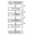
次に、このようにして把握可能な重畳画像のずれ量にもとづいて、重畳画像20の画合わせをおこなう方法について、図5から図8を用いて説明する。図5は、第1の実施形態の画合わせ調整処理のフローチャートを示す図である。図6は、第1の実施形態のズーム調整処理のフローチャートを示す図である。図7は、第1の実施形態のずれ量検出処理のフローチャートを示す図である。図8は、第1の実施形態の投影位置調整処理のフローチャートを示す図である。 Next, a method of performing image alignment of the superimposed image 20 based on the amount of deviation of the superimposed image that can be grasped in this way will be described with reference to FIGS. FIG. 5 is a diagram illustrating a flowchart of the image matching adjustment process according to the first embodiment. FIG. 6 is a diagram illustrating a flowchart of zoom adjustment processing according to the first embodiment. FIG. 7 is a diagram illustrating a flowchart of the shift amount detection process according to the first embodiment. FIG. 8 is a flowchart of the projection position adjustment process according to the first embodiment.
まず、制御装置2が実行する画合わせ調整処理について説明する。制御装置2は、重畳画像20の画合わせを調整する際に、画合わせ調整処理を実行する。制御装置2は、画合わせの調整を指示する操作入力や、プロジェクタ5,8の初期化時や、プロジェクタ5,8による投影開始時、投影する映像コンテンツの切替時などのイベント発生タイミングなどの所定のタイミングで、画合わせ調整処理を実行することができる。 First, the image matching adjustment process executed by the
[ステップS11]制御装置2は、プロジェクタ5,8にテストパタンの表示を指示する。プロジェクタ5は、制御装置2からのテストパタンの表示の指示を受けて、投影画像11にテストパタン23,27を含ませて投影をおこなう。プロジェクタ8は、制御装置2からのテストパタンの表示の指示を受けて、投影画像12にテストパタン22,28を含ませて投影をおこなう。 [Step S11] The
[ステップS12]制御装置2は、プロジェクタ5,8が表示するテストパタンにもとづいて投射レンズのズーム調整をおこなうズーム調整処理を実行する。ズーム調整処理の詳細は、後で説明する。 [Step S12] The
[ステップS13]制御装置2は、ズーム調整処理を実行後の、プロジェクタ5,8が表示するテストパタンにもとづいて、投影位置の調整をおこなう投影位置調整処理を実行する。投影位置調整処理の詳細は、後で説明する。 [Step S13] The
[ステップS14]制御装置2は、プロジェクタ5,8にテストパタンのクリアを指示する。プロジェクタ5は、制御装置2からのテストパタンのクリアの指示を受けて、テストパタン23,27をクリアした投影画像11の投影をおこなう。プロジェクタ8は、制御装置2からのテストパタンのクリアの指示を受けて、テストパタン22,28をクリアした投影画像12の投影をおこなう。制御装置2は、プロジェクタ5,8にテストパタンのクリアを指示した後、画合わせ調整処理を終了する。 [Step S14] The
このように、制御装置2は、プロジェクタ5,8について投射レンズのズーム調整をおこない、投射レンズを駆動した際に生ずるメカ機構の誤差を収束させたうえで、投影位置誤差の調整をおこなう。これにより、制御装置2は、投影システム1の画合わせを効率的におこなうことを可能にしている。 In this way, the
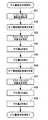
次に、制御装置2が実行するズーム調整処理について説明する。制御装置2は、画合わせ調整処理のステップS12でズーム調整処理を実行する。 Next, zoom adjustment processing executed by the
[ステップS21]制御装置2は、プロジェクタ5,8が表示するテストパタンにもとづいて投影画像11と投影画像12とのずれ量を検出するずれ量検出処理を実行する。 [Step S21] The
ここで、ステップS22の説明の前に、ずれ量検出処理について説明する。ずれ量検出処理では、図3、図4を用いて説明したずれ量a,b,c,dを検出する。 Here, the shift amount detection process will be described before the description of step S22. In the shift amount detection process, the shift amounts a, b, c, and d described with reference to FIGS. 3 and 4 are detected.
[ステップS31]制御装置2は、テストパタン22,23を含む撮影画像21を撮影装置15から取得する。また、制御装置2は、テストパタン27,28を含む撮影画像29を撮影装置16から取得する。 [Step S <b> 31] The
[ステップS32]制御装置2は、撮影画像21をスキャンライン40で走査する。 [Step S <b> 32] The
[ステップS33]制御装置2は、スキャンライン40とテストパタン22,23とが交差する交差点32,33,36,37を特定する。 [Step S33] The
[ステップS34]制御装置2は、交差点32と交差点33とからずれ量aを検出する。ずれ量aは、投影画像11と投影画像12の水平成分の誤差を情報として含む。 [Step S34] The
[ステップS35]制御装置2は、交差点36と交差点37とからずれ量bを検出する。ずれ量bは、投影画像11と投影画像12の垂直成分の誤差を情報として含む。 [Step S35] The
[ステップS36]制御装置2は、撮影画像29をスキャンライン51で走査する。 [Step S <b> 36] The
[ステップS37]制御装置2は、スキャンライン51とテストパタン27,28とが交差する交差点43,44,47,48を特定する。 [Step S37] The
[ステップS38]制御装置2は、交差点43と交差点44とからずれ量cを検出する。ずれ量cは、投影画像11と投影画像12の垂直成分の誤差を情報として含む。 [Step S38] The
[ステップS39]制御装置2は、交差点47と交差点48とからずれ量dを検出する。ずれ量dは、投影画像11と投影画像12の水平成分の誤差を情報として含む。 [Step S39] The
制御装置2は、ずれ量a,b,c,dを検出して、ずれ量検出処理を終了する。 The
なお、スキャンライン40は、撮影画像21の水平線であり、スキャンライン51は、撮影画像29の水平線である。このように、スキャンライン40,51を設定することで、ずれ量a,b,c,dの検出が容易となり、制御装置2の信号処理に係る負担は、軽減される。 Note that the
ここで、再び、ズーム調整処理の説明に戻る。
[ステップS22]制御装置2は、ずれ量検出処理によって検出したずれ量a,dにもとづいてズーム誤差を検出する。ズーム誤差は、ずれ量aとずれ量dとの差分(=|a−d|)として算出することができる。なお、ズーム誤差は、ずれ量検出処理によって検出したずれ量bとずれ量cとの差分(=|b−c|)として算出することもできる。Here, the description returns to the zoom adjustment processing again.
[Step S22] The
[ステップS23]制御装置2は、検出したズーム誤差があらかじめ設定した許容範囲内にあるか否かを判定する。制御装置2は、ズーム誤差が許容範囲内にある場合には、ズーム調整をおこなうことなくズーム調整処理を終了する。一方、制御装置2は、ズーム誤差が許容範囲内にない場合には、ステップS24にすすむ。 [Step S23] The
[ステップS24]制御装置2は、算出したズーム誤差にもとづいて、プロジェクタ5の投射レンズのズーム量と、プロジェクタ8の投射レンズのズーム量のうち、少なくともいずれか一方のズーム量を調整する調整量(ズーム調整量)を算出する。たとえば、制御装置2は、プロジェクタ5,8の投射レンズのズーム量のうち、いずれか一方を基準とする場合、他方についてのズーム調整量を算出する。あるいは、制御装置2は、別途定める基準がある場合、プロジェクタ5,8の投射レンズのズーム量の両方についてズーム調整量を算出する。 [Step S24] The
[ステップS25]制御装置2は、算出したズーム調整量を対応するプロジェクタに指示する。制御装置2は、プロジェクタ5,8の投射レンズのズーム量の調整後、ステップS21に戻る。なお、制御装置2は、プロジェクタ5,8の投射レンズのズーム量の調整後の確認を要しない場合には、ズーム調整処理を終了するようにしてもよい。 [Step S25] The
このようにして、投影システム1は、重畳画像20における投影画像11と投影画像12のズーム量の調整をおこなうことができる。 In this manner, the projection system 1 can adjust the zoom amount of the projection image 11 and the projection image 12 in the superimposed image 20.
次に、制御装置2が実行する投影位置調整処理について説明する。制御装置2は、画合わせ調整処理のステップS13で投影位置調整処理を実行する。 Next, the projection position adjustment process executed by the
[ステップS41]制御装置2は、ずれ量検出処理を実行する。制御装置2は、投射レンズのズーム量の調整後の撮影画像21,29にもとづいて、ずれ量a,b,c,dの検出をおこなう。 [Step S41] The
[ステップS42]制御装置2は、ずれ量検出処理によって検出したずれ量a,dにもとづいて水平方向の投影位置誤差を検出する。制御装置2は、ずれ量aとずれ量dとの和(=a+d)として水平方向の投影位置誤差を算出することができる。 [Step S42] The
[ステップS43]制御装置2は、検出した水平方向の投影位置誤差があらかじめ設定した許容範囲内にあるか否かを判定する。制御装置2は、水平方向の投影位置誤差が許容範囲内にある場合には、ステップS45にすすみ、水平方向の投影位置誤差が許容範囲内にない場合には、ステップS44にすすむ。 [Step S43] The
[ステップS44]制御装置2は、算出した水平方向の投影位置誤差にもとづいて、投影画像11の水平方向の投影位置と、投影画像12の水平方向の投影位置のうち、少なくともいずれか一方の投影位置を調整する調整量(水平方向の投影位置調整量)を算出する。たとえば、制御装置2は、投影画像11,12の投影位置のうち、いずれか一方を基準とする場合、他方についての水平方向の投影位置調整量を算出する。あるいは、制御装置2は、別途定める基準がある場合、投影画像11,12の投影位置の両方について水平方向の投影位置調整量を算出する。 [Step S44] The
[ステップS45]制御装置2は、ずれ量検出処理によって検出したずれ量b,cにもとづいて垂直方向の投影位置誤差を検出する。制御装置2は、ずれ量bとずれ量cとの和(=b+c)として垂直方向の投影位置誤差を算出することができる。 [Step S45] The
[ステップS46]制御装置2は、検出した垂直方向の投影位置誤差があらかじめ設定した許容範囲内にあるか否かを判定する。制御装置2は、垂直方向の投影位置誤差が許容範囲内にある場合には、ステップS48にすすみ、垂直方向の投影位置誤差が許容範囲内にない場合には、ステップS47にすすむ。 [Step S46] The
[ステップS47]制御装置2は、算出した垂直方向の投影位置誤差にもとづいて、投影画像11の垂直方向の投影位置と、投影画像12の垂直方向の投影位置のうち、少なくともいずれか一方の投影位置を調整する調整量(垂直方向の投影位置調整量)を算出する。たとえば、制御装置2は、投影画像11,12の投影位置のうち、いずれか一方を基準とする場合、他方についての垂直方向の投影位置調整量を算出する。あるいは、制御装置2は、別途定める基準がある場合、投影画像11,12の投影位置の両方について垂直方向の投影位置調整量を算出する。 [Step S47] The
[ステップS48]制御装置2は、投影画像11,12の投影位置について、水平方向の投影位置調整量と垂直方向の投影位置調整量のうち少なくともいずれか一方が算出されているか否かを判定する。制御装置2は、水平方向の投影位置調整量と垂直方向の投影位置調整量のうち少なくともいずれか一方が算出されている場合にステップS49にすすみ、いずれも算出されていない場合に投影位置調整処理を終了する。 [Step S48] The
[ステップS49]制御装置2は、算出した水平方向の投影位置調整量、または垂直方向の投影位置調整量のうち一方を、あるいは両方を、対応するプロジェクタに指示する。制御装置2は、投影画像11,12の投影位置の調整後、ステップS41に戻る。なお、制御装置2は、投影画像11,12の投影位置の調整後の確認を要しない場合には、投影位置調整処理を終了するようにしてもよい。 [Step S49] The
このようにして、投影システム1は、重畳画像20における投影画像11と投影画像12の投影位置調整処理の調整をおこなうことができる。また、このような投影システム1によれば、高い解像度を必要としないキャプチャ用カメラを用いることが可能であって、重畳画像の画合わせの調整を、簡素な信号処理によって精度よくおこなうことができる。 In this way, the projection system 1 can adjust the projection position adjustment processing of the projection image 11 and the projection image 12 in the superimposed image 20. Moreover, according to such a projection system 1, it is possible to use a capture camera that does not require a high resolution, and it is possible to accurately adjust the alignment of superimposed images by simple signal processing. .
次に、第1の実施形態の制御装置のハードウェア構成について図9を用いて説明する。図9は、第1の実施形態の制御装置のハードウェア構成の一例を示す図である。 Next, the hardware configuration of the control device according to the first embodiment will be described with reference to FIG. FIG. 9 is a diagram illustrating an example of a hardware configuration of the control device according to the first embodiment.
制御装置2は、CPU(Central Processing Unit)101によって統括的に制御される。CPU101には、バス107を介してRAM(Random Access Memory)102、ROM(Read Only Memory)103、通信インタフェース104、グラフィック処理装置105、および入出力インタフェース106が接続されている。 The
RAM102には、CPU101に実行させるOS(Operating System)のプログラムやアプリケーションプログラムの少なくとも一部が一時的に格納される。また、RAM102には、CPU101による処理に必要な各種データが格納される。ROM103には、OSやアプリケーションプログラムが格納される。また、ROM103には、対応情報が格納される。 The
グラフィック処理装置105には、図示しない表示装置が接続される。入出力インタフェース106には、図示しないマウスやキーボードなどの各種入出力装置が接続される。また、入出力インタフェース106は、可搬型記録媒体110への情報の書込み、および可搬型記録媒体110への情報の読出しが可能な可搬型記録媒体インタフェースと接続可能になっている。各種入出力装置は、入出力インタフェース106、バス107を介してCPU101と情報の入出力をおこなう。通信インタフェース104は、他の装置(たとえば、プロジェクタ5,8、撮影装置15,16など)との間でデータの送受信をおこなう。 A display device (not shown) is connected to the
以上のようなハードウェア構成によって、本実施の形態の処理機能(ズーム量制御部3、投影位置制御部4)を実現することができる。 With the hardware configuration described above, the processing functions (zoom
なお、制御装置2は、汎用のコンピュータを用いることができる。たとえば、制御装置2は、ノート型パーソナルコンピュータなどであってもよい。 The
なお、制御装置2は、それぞれFPGA(Field Programmable Gate Array)やDSP(Digital Signal Processer)などからなるモジュールを含んで構成することもでき、CPU101を有しない構成とすることもできる。その場合、制御装置2は、それぞれ不揮発性メモリ(たとえば、EEPROM(Electrically Erasable Programmable ROM)、フラッシュメモリ、フラッシュメモリ型メモリカードなど)を備え、モジュールのファームウェアを記憶する。不揮発性メモリは、可搬型記録媒体110、あるいは通信インタフェース104を介してファームウェアを書き込むことができる。このように制御装置2は、不揮発性メモリに記憶されているファームウェアを書き換えることにより、ファームウェアの更新をすることもできる。 The
次に、第1の実施形態のプロジェクタの構成および外部装置との接続について図10を用いて説明する。図10は、第1の実施形態のプロジェクタの構成および外部装置との接続の一例を示す図である。 Next, the configuration of the projector according to the first embodiment and the connection with an external device will be described with reference to FIG. FIG. 10 is a diagram illustrating an example of the configuration of the projector according to the first embodiment and connection with an external device.
プロジェクタ5,8は、制御装置2から調整情報を取得可能にして制御装置2と接続し、コンテンツサーバ17から画像情報を取得可能にしてコンテンツサーバ17と接続する。コンテンツサーバ17は、プロジェクタ5,8が投影する映像コンテンツを画像情報として保持する。 The
プロジェクタ5は、制御部60と、画像処理部61と、駆動部62と、投影部63と、投射レンズ64を備える。制御部60は、プロジェクタ5を統括的に制御する。画像処理部61は、コンテンツサーバ17から取得した画像情報にもとづいて、投影画像11の投影位置(水平方向の投影位置、および垂直方向の投影位置)を決定する。また、画像処理部61は、制御装置2から取得した調整情報にもとづいて、投影画像11の投影位置(水平方向の投影位置、および垂直方向の投影位置)を調整(決定)する。画像処理部61は、信号処理により投影位置の決定をおこなうため、調整情報にもとづく投影画像11の投影位置の調整を厳密におこなうことができる。また、画像処理部61は、制御装置2からの指示を受けて、テストパタンを表示内容に加えることができる。また、画像処理部61は、制御装置2からの指示を受けて、テストパタンを表示内容からクリアすることができる。 The
投影部63は、画像処理部61が決定した投影位置にしたがい、投影画像11をスクリーンに投影する。駆動部62は、モータなどの駆動機構により、投射レンズ64を駆動する。プロジェクタ5は、投射レンズ64を駆動することでズーム調整をおこなう。このとき、投射レンズを駆動するメカ機構のがたや撓みなどの誤差により、投影位置が変化する場合があるため、投影システム1は、投影位置の調整に先行して、ズーム調整をおこなう。以上、プロジェクタ5について説明したが、プロジェクタ8についても同様である。 The
次に、第1の実施形態の重畳画像におけるテストパタンの表示と、撮影範囲の変形例について図11を用いて説明する。図11は、第1の実施形態の重畳画像におけるテストパタンの表示と、撮影範囲の変形例を示す図である。 Next, the display of the test pattern in the superimposed image of the first embodiment and a modified example of the shooting range will be described with reference to FIG. FIG. 11 is a diagram illustrating a test pattern display in the superimposed image of the first embodiment and a modification of the imaging range.
重畳画像80は、重畳画像80の左辺中央部に位置する撮影範囲81にテストパタン82,83を表示し、重畳画像80の右辺中央部に位置する撮影範囲86にテストパタン84,85を表示する。このように、重畳画像80は、重畳画像80の中央部からテストパタンが十分な距離を有することで、重畳画像80の四隅とならない位置にテストパタンを表示することができる。これにより、投影システム1は、重畳画像の観察者(たとえば、映画の観客)がいる場合に、観察者の注意が喚起されない位置にテストパタンを配置することができる。 The superimposed image 80 displays test
なお、第1の実施形態の投影システム1について、2枚の画像をスクリーン上で重ね合わせる例を用いて説明したが、スクリーン上に重ね合わせる画像は、3枚以上であってもよい。たとえば、3枚以上の画像をスクリーン上で重ね合わせる投射システムは、基準となる画像に、その他の画像を1枚ずつ重ね合わせることで、すなわち2枚の画像のスクリーン上での重ね合わせを繰り返すことで実現することができる。 Although the projection system 1 of the first embodiment has been described using an example in which two images are superimposed on the screen, three or more images may be superimposed on the screen. For example, a projection system that superimposes three or more images on a screen repeats the superimposition of two images on the screen by superimposing other images one by one on the reference image. Can be realized.
[第2の実施形態]
次に、第2の実施形態の投影システムについて図12を用いて説明する。図12は、第2の実施形態の投影システムにおける撮影装置の撮影範囲の一例を示す図である。[Second Embodiment]
Next, the projection system of 2nd Embodiment is demonstrated using FIG. FIG. 12 is a diagram illustrating an example of an imaging range of the imaging device in the projection system of the second embodiment.
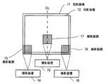
第1の実施形態において、プロジェクタ5,8は、各々投影画像11,12の左下隅部と右下隅部にテストパタンを表示していたが、第2の実施形態においては、プロジェクタ5,8は、左下隅部と右下隅部に加えて中央部にテストパタンを表示する。なお、第1の実施形態と同様の構成については、符号を同一にして説明を省略する。 In the first embodiment, the
第2の実施形態の投影システムは、撮影装置74,75,76を備える。プロジェクタ5は、スクリーンに投影画像71を投影し、プロジェクタ8は、スクリーンに投影画像72を投影する。プロジェクタ5は、投影画像71の左下隅部、右下隅部および中央部にテストパタンを投影する。プロジェクタ8は、投影画像72の左下隅部、右下隅部および中央部にテストパタンを投影する。 The projection system of the second embodiment includes photographing
撮影装置74は、投影画像71と投影画像72が重畳して投影される領域を含む撮影範囲73を撮影する撮影装置である。撮影装置75は、投影画像71と投影画像72が重畳して投影される領域を含む撮影範囲77を撮影する撮影装置である。撮影装置76は、投影画像71と投影画像72が重畳して投影される領域を含む撮影範囲78を撮影する撮影装置である。なお、撮影範囲77は、投影画像71と投影画像72の中心線CL上の、撮影範囲73と撮影範囲78との間に位置することが望ましい。 The
制御装置2は、投影画像71と投影画像72の画合わせを制御する。制御装置2は、撮影装置74から入力する画像情報と、撮影装置75から入力する画像情報と、撮影装置76から入力する画像情報とから、調整情報を決定する。 The
制御装置2は、撮影装置74から入力する画像情報と撮影装置76から入力する画像情報とから生成する調整情報にもとづいて、プロジェクタ5,8の両方、あるいはいずれか一方に、投射レンズのズーム位置の調整の指示をおこなう。 Based on the adjustment information generated from the image information input from the
制御装置2は、ズーム量調整後の撮影装置75から入力する画像情報から生成する調整情報にもとづいて、プロジェクタ5,8の両方、あるいはいずれか一方に、投影画像の画像中心位置の調整の指示をおこなう。 The
このように、投影システム1は、3以上の撮影範囲によって、投射レンズのズーム位置の調整と、投影画像の画像中心位置の調整をおこなうようにしてもよい。その場合、投影システム1は、投射レンズのズーム位置の調整に用いる撮影範囲と、投影画像の画像中心位置の調整に用いる調整範囲とに役割を分担するようにしてもよい。 As described above, the projection system 1 may adjust the zoom position of the projection lens and the image center position of the projection image according to three or more photographing ranges. In that case, the projection system 1 may share a role between a shooting range used for adjusting the zoom position of the projection lens and an adjustment range used for adjusting the image center position of the projection image.
なお、本技術は以下のような構成も採ることができる。
(1)第1の画像を投影する第1の投影装置と、
第2の画像を投影する第2の投影装置と、
前記第1の画像と前記第2の画像が重畳した重畳画像の第1の隅部を撮影する第1の撮影装置と、
前記重畳画像の第2の隅部を撮影する第2の撮影装置と、
前記第1の隅部の撮影画像と前記第2の隅部の撮影画像とから、前記第1の画像と前記第2の画像の画合わせを制御する制御装置と、
を備え、
前記制御装置は、
前記第1の隅部の撮影画像と前記第2の隅部の撮影画像とから前記第1の投影装置のレンズのズーム量と前記第2の投影装置のレンズのズーム量とのズーム誤差を検出し、前記ズーム誤差にもとづくズームの調整量を、前記第1の投影装置と前記第2の投影装置とに指示するズーム量制御部と、
ズーム量調整後の前記第1の隅部の撮影画像と、ズーム量調整後の前記第2の隅部の撮影画像とから、前記第1の投影装置の投影位置と前記第2の投影装置の投影位置との投影位置誤差を検出し、前記投影位置誤差にもとづく投影位置の調整量を、前記第1の投影装置と前記第2の投影装置とに指示する投影位置制御部と、
を備える投影システム。
(2)前記第1の画像は、前記第1の隅部に相当する位置に第1のテストパタンと、前記第2の隅部に相当する位置に第2のテストパタンと、を含み、
前記第2の画像は、前記第1の隅部に相当する位置に第3のテストパタンと、前記第2の隅部に相当する位置に第4のテストパタンと、を含み、
前記制御装置は、前記第1のテストパタンと前記第3のテストパタンのずれ量と、前記第2のテストパタンと前記第4のテストパタンのずれ量とから、前記第1の画像と前記第2の画像の画合わせを制御する、
前記(1)記載の投影システム。
(3)前記第1のテストパタン、前記第2のテストパタン、前記第3のテストパタン、および前記第4のテストパタンは、それぞれ、水平線である第1の直線と、垂直線である第2の直線と、を含む前記(2)記載の投影システム。
(4)前記第1のテストパタン、前記第2のテストパタン、前記第3のテストパタン、および前記第4のテストパタンは、それぞれ、所定の水平成分と所定の垂直成分を有する第1の直線と、前記第1の直線と異なる所定の水平成分と前記第1の直線と異なる所定の垂直成分とを有する第2の直線と、を含む前記(2)記載の投影システム。
(5)前記第1の隅部および前記第2の隅部は、それぞれ前記重畳画像の四隅のうちの1つであって、
前記第1のテストパタン、前記第2のテストパタン、前記第3のテストパタン、および前記第4のテストパタンは、それぞれ、前記第1の直線と前記第2の直線とでL字状のテストパタンを形成し、
前記L字状のテストパタンは、前記第1のテストパタン、前記第2のテストパタン、前記第3のテストパタン、および前記第4のテストパタンにおいて、前記第1の直線と前記第2の直線が前記重畳画像の周縁部に位置する向きとなる、
前記(3)記載の投影システム。
(6)前記第1の撮影装置は、前記第1の隅部の撮影画像の垂直線が、前記重畳画像の中心を向く方向に設置され、
前記第2の撮影装置は、前記第2の隅部の撮影画像の垂直線が、前記重畳画像の中心を向く方向に設置される、
前記(5)記載の投影システム。
(7)前記制御装置は、
前記第1のテストパタンが含む前記第1の直線と、前記第3のテストパタンが含む前記第1の直線と、のずれ量を検出する第1検出部と、
前記第1のテストパタンが含む前記第2の直線と、前記第3のテストパタンが含む前記第2の直線と、のずれ量を検出する第2検出部と、
前記第2のテストパタンが含む前記第1の直線と、前記第4のテストパタンが含む前記第1の直線と、のずれ量を検出する第3検出部と、
前記第2のテストパタンが含む前記第2の直線と、前記第4のテストパタンが含む前記第2の直線と、のずれ量を検出する第4検出部と、
を備える前記(3)乃至(6)のいずれか1つに記載の投影システム。
(8)前記制御装置は、
前記第1のテストパタンが含む前記第1の直線と、前記第3のテストパタンが含む前記第1の直線と、前記第1のテストパタンが含む前記第2の直線と、前記第3のテストパタンが含む前記第2の直線のすべてと交わる直線を第1の走査線として、前記第1の隅部の撮影画像を走査する第1走査部と、
前記第2のテストパタンが含む前記第1の直線と、前記第4のテストパタンが含む前記第1の直線と、前記第2のテストパタンが含む前記第2の直線と、前記第4のテストパタンが含む前記第2の直線のすべてと交わる直線を第2の走査線として、前記第2の隅部の撮影画像を走査する第2走査部と、
を備え、
前記第1検出部は、前記第1のテストパタンが含む前記第1の直線と前記第1の走査線との交点と、前記第3のテストパタンが含む前記第1の直線と前記第1の走査線との交点と、により、前記第1のテストパタンが含む前記第1の直線と、前記第3のテストパタンが含む前記第1の直線とのずれ量を検出し、
前記第2検出部は、前記第1のテストパタンが含む前記第2の直線と前記第1の走査線との交点と、前記第3のテストパタンが含む前記第2の直線と前記第1の走査線との交点と、により、前記第1のテストパタンが含む前記第2の直線と、前記第3のテストパタンが含む前記第2の直線とのずれ量を検出し、
前記第3検出部は、前記第2のテストパタンが含む前記第1の直線と前記第2の走査線との交点と、前記第4のテストパタンが含む前記第1の直線と前記第2の走査線との交点と、により、前記第2のテストパタンが含む前記第1の直線と、前記第4のテストパタンが含む前記第1の直線とのずれ量を検出し、
前記第4検出部は、前記第2のテストパタンが含む前記第2の直線と前記第2の走査線との交点と、前記第4のテストパタンが含む前記第2の直線と前記第2の走査線との交点と、により、前記第2のテストパタンが含む前記第2の直線と、前記第4のテストパタンが含む前記第2の直線とのずれ量を検出する、
前記(7)記載の投影システム。
(9)前記ズーム量制御部は、
前記第1のテストパタンが含む前記第1の直線と、前記第3のテストパタンが含む前記第1の直線とのずれ量と、
前記第2のテストパタンが含む前記第1の直線と、前記第4のテストパタンが含む前記第1の直線とのずれ量と、の差から前記ズーム誤差を検出する、
前記(8)記載の投影システム。
(10)前記ズーム量制御部は、
前記第1のテストパタンが含む前記第2の直線と、前記第3のテストパタンが含む前記第2の直線とのずれ量と、
前記第2のテストパタンが含む前記第2の直線と、前記第4のテストパタンが含む前記第2の直線とのずれ量と、の差から前記ズーム誤差を検出する、
前記(8)記載の投影システム。
(11)前記投影位置制御部は、
前記第1のテストパタンが含む前記第1の直線と、前記第3のテストパタンが含む前記第1の直線とのずれ量と、
前記第2のテストパタンが含む前記第1の直線と、前記第4のテストパタンが含む前記第1の直線とのずれ量と、の和から、水平方向の投影位置誤差を検出する、
前記(8)乃至(10)のいずれか1つに記載の投影システム。
(12)前記投影位置制御部は、
前記第1のテストパタンが含む前記第2の直線と、前記第3のテストパタンが含む前記第2の直線とのずれ量と、
前記第2のテストパタンが含む前記第2の直線と、前記第4のテストパタンが含む前記第2の直線とのずれ量と、の和から、垂直方向の投影位置誤差を検出する、
前記(8)乃至(11)のいずれか1つに記載の投影システム。
(13)第1の画像を投影する第1の投影装置と、
第2の画像を投影する第2の投影装置と、
前記第1の画像と前記第2の画像が重畳した重畳画像の第1の隅部を撮影する第1の撮影装置と、
前記重畳画像の第2の隅部を撮影する第2の撮影装置と、
前記重畳画像の中間部を撮影する第3の撮影装置と、
前記第1の隅部の撮影画像と前記第2の隅部の撮影画像と前記中間部の撮影画像とから、前記第1の画像と前記第2の画像の画合わせを制御する制御装置と、
を備え、
前記制御装置は、
前記第1の隅部の撮影画像と前記第2の隅部の撮影画像とから前記第1の投影装置のレンズのズーム量と前記第2の投影装置のレンズのズーム量とのズーム誤差を検出し、前記ズーム誤差にもとづくズームの調整量を、前記第1の投影装置と前記第2の投影装置とに指示するズーム量制御部と、
ズーム量調整後の前記中間部の撮影画像から、前記第1の投影装置の投影位置と前記第2の投影装置の投影位置との投影位置誤差を検出し、前記投影位置誤差にもとづく投影位置の調整量を、前記第1の投影装置と前記第2の投影装置とに指示する投影位置制御部と、
を備える投影システム。
(14)第1の投影装置が投影する第1の画像と、第2の投影装置が投影する第2の画像との重畳画像の画合わせの調整方法であって、
前記重畳画像の第1の隅部を撮影するステップと、
前記重畳画像の第2の隅部を撮影するステップと、
前記第1の隅部の撮影画像と前記第2の隅部の撮影画像とから前記第1の投影装置のレンズのズーム量と前記第2の投影装置のレンズのズーム量とのズーム誤差を検出するステップと、
前記ズーム誤差にしたがった前記第1の投影装置のレンズのズーム量の調整と、前記ズーム誤差にしたがった前記第2の投影装置のレンズのズーム量の調整のうち、少なくともいずれか一方を実行するステップと、
ズーム量調整後の前記第1の隅部の撮影画像と、ズーム量調整後の前記第2の隅部の撮影画像とから、前記第1の投影装置の投影位置と前記第2の投影装置の投影位置との投影位置誤差を検出するステップと、
前記投影位置誤差にしたがった前記第1の投影装置の投影位置の調整と、前記投影位置誤差にしたがった前記第2の投影装置の投影位置の調整のうち、少なくともいずれか一方を実行するステップと、
を含む重畳画像の画合わせの調整方法。In addition, this technique can also take the following structures.
(1) a first projection device that projects a first image;
A second projection device for projecting a second image;
A first imaging device that captures a first corner of a superimposed image in which the first image and the second image are superimposed;
A second imaging device for imaging a second corner of the superimposed image;
A control device that controls image alignment of the first image and the second image from the captured image of the first corner and the captured image of the second corner;
With
The controller is
A zoom error between the zoom amount of the lens of the first projector and the zoom amount of the lens of the second projector is detected from the captured image of the first corner and the captured image of the second corner. A zoom amount control unit that instructs the first projection device and the second projection device to adjust the zoom amount based on the zoom error;
From the captured image of the first corner after adjusting the zoom amount and the captured image of the second corner after adjusting the zoom amount, the projection position of the first projection device and the second projection device A projection position controller that detects a projection position error with respect to the projection position, and instructs the first projection apparatus and the second projection apparatus to adjust a projection position adjustment amount based on the projection position error;
A projection system comprising:
(2) The first image includes a first test pattern at a position corresponding to the first corner, and a second test pattern at a position corresponding to the second corner.
The second image includes a third test pattern at a position corresponding to the first corner, and a fourth test pattern at a position corresponding to the second corner,
The control device determines whether the first image and the third test pattern are offset from the shift amount between the first test pattern and the third test pattern, and the shift amount between the second test pattern and the fourth test pattern. Control the alignment of the two images,
The projection system according to (1).
(3) The first test pattern, the second test pattern, the third test pattern, and the fourth test pattern are respectively a first straight line that is a horizontal line and a second line that is a vertical line. The projection system according to (2), including:
(4) The first test pattern, the second test pattern, the third test pattern, and the fourth test pattern each have a first straight line having a predetermined horizontal component and a predetermined vertical component. And a second straight line having a predetermined horizontal component different from the first straight line and a predetermined vertical component different from the first straight line.
(5) The first corner and the second corner are each one of four corners of the superimposed image,
The first test pattern, the second test pattern, the third test pattern, and the fourth test pattern are L-shaped tests on the first straight line and the second straight line, respectively. Forming a pattern,
The L-shaped test pattern includes the first straight line and the second straight line in the first test pattern, the second test pattern, the third test pattern, and the fourth test pattern. Is the direction located at the peripheral edge of the superimposed image,
The projection system according to (3).
(6) The first photographing device is installed in a direction in which a vertical line of the photographed image at the first corner faces the center of the superimposed image,
The second imaging device is installed in a direction in which a vertical line of a captured image at the second corner faces the center of the superimposed image,
The projection system according to (5).
(7) The control device includes:
A first detection unit that detects a shift amount between the first straight line included in the first test pattern and the first straight line included in the third test pattern;
A second detector for detecting a deviation amount between the second straight line included in the first test pattern and the second straight line included in the third test pattern;
A third detector for detecting a shift amount between the first straight line included in the second test pattern and the first straight line included in the fourth test pattern;
A fourth detector for detecting a shift amount between the second straight line included in the second test pattern and the second straight line included in the fourth test pattern;
The projection system according to any one of (3) to (6).
(8) The control device includes:
The first straight line included in the first test pattern, the first straight line included in the third test pattern, the second straight line included in the first test pattern, and the third test. A first scanning unit that scans a captured image of the first corner using a straight line that intersects all of the second straight lines included in the pattern as a first scanning line;
The first straight line included in the second test pattern, the first straight line included in the fourth test pattern, the second straight line included in the second test pattern, and the fourth test. A second scanning unit that scans a captured image of the second corner using a straight line that intersects all of the second straight lines included in the pattern as a second scanning line;
With
The first detection unit includes an intersection of the first straight line included in the first test pattern and the first scanning line, the first straight line included in the third test pattern, and the first straight line. Detecting an amount of deviation between the first straight line included in the first test pattern and the first straight line included in the third test pattern based on the intersection with the scanning line;
The second detection unit includes an intersection between the second straight line included in the first test pattern and the first scanning line, the second straight line included in the third test pattern, and the first straight line. Detecting an amount of deviation between the second straight line included in the first test pattern and the second straight line included in the third test pattern based on the intersection with the scanning line;
The third detection unit includes an intersection between the first straight line included in the second test pattern and the second scanning line, the first straight line included in the fourth test pattern, and the second Detecting an amount of deviation between the first straight line included in the second test pattern and the first straight line included in the fourth test pattern based on the intersection with the scanning line;
The fourth detector includes an intersection of the second straight line included in the second test pattern and the second scanning line, the second straight line included in the fourth test pattern, and the second Detecting an amount of deviation between the second straight line included in the second test pattern and the second straight line included in the fourth test pattern based on an intersection with the scanning line;
The projection system according to (7).
(9) The zoom amount control unit
A deviation amount between the first straight line included in the first test pattern and the first straight line included in the third test pattern;
Detecting the zoom error from a difference between a shift amount between the first straight line included in the second test pattern and the first straight line included in the fourth test pattern;
The projection system according to (8).
(10) The zoom amount control unit
A deviation amount between the second straight line included in the first test pattern and the second straight line included in the third test pattern;
Detecting the zoom error from a difference between a shift amount between the second straight line included in the second test pattern and the second straight line included in the fourth test pattern;
The projection system according to (8).
(11) The projection position controller
A deviation amount between the first straight line included in the first test pattern and the first straight line included in the third test pattern;
A horizontal projection position error is detected from the sum of the shift amount between the first straight line included in the second test pattern and the first straight line included in the fourth test pattern;
The projection system according to any one of (8) to (10).
(12) The projection position controller
A deviation amount between the second straight line included in the first test pattern and the second straight line included in the third test pattern;
A vertical projection position error is detected from a sum of a shift amount between the second straight line included in the second test pattern and the second straight line included in the fourth test pattern;
The projection system according to any one of (8) to (11).
(13) a first projection device that projects a first image;
A second projection device for projecting a second image;
A first imaging device that captures a first corner of a superimposed image in which the first image and the second image are superimposed;
A second imaging device for imaging a second corner of the superimposed image;
A third photographing device for photographing an intermediate portion of the superimposed image;
A control device for controlling image alignment of the first image and the second image from the captured image of the first corner, the captured image of the second corner, and the captured image of the intermediate portion;
With
The controller is
A zoom error between the zoom amount of the lens of the first projector and the zoom amount of the lens of the second projector is detected from the captured image of the first corner and the captured image of the second corner. A zoom amount control unit that instructs the first projection device and the second projection device to adjust the zoom amount based on the zoom error;
A projection position error between the projection position of the first projection apparatus and the projection position of the second projection apparatus is detected from the captured image of the intermediate portion after the zoom amount adjustment, and the projection position based on the projection position error is detected. A projection position control unit for instructing the adjustment amount to the first projection device and the second projection device;
A projection system comprising:
(14) An adjustment method for image alignment of a superimposed image of a first image projected by a first projection device and a second image projected by a second projection device,
Photographing a first corner of the superimposed image;
Photographing a second corner of the superimposed image;
A zoom error between the zoom amount of the lens of the first projector and the zoom amount of the lens of the second projector is detected from the captured image of the first corner and the captured image of the second corner. And steps to
At least one of adjustment of the zoom amount of the lens of the first projection device according to the zoom error and adjustment of the zoom amount of the lens of the second projection device according to the zoom error is executed. Steps,
From the captured image of the first corner after adjusting the zoom amount and the captured image of the second corner after adjusting the zoom amount, the projection position of the first projection device and the second projection device Detecting a projection position error from the projection position;
Executing at least one of adjustment of the projection position of the first projection apparatus according to the projection position error and adjustment of the projection position of the second projection apparatus according to the projection position error; ,
Adjustment method of superimposed image including image.
なお、上述の実施の形態は、実施の形態の要旨を逸脱しない範囲内において種々の変更を加えることができる。 Note that various modifications can be made to the above-described embodiment without departing from the gist of the embodiment.
さらに、上述の実施の形態は、多数の変形、変更が当業者にとって可能であり、説明した正確な構成および応用例に限定されるものではない。 Further, the above-described embodiments can be modified and changed by those skilled in the art, and are not limited to the exact configurations and application examples described.
1……投影システム、2……制御装置、3……ズーム量制御部、4……投影位置制御部、5,8……プロジェクタ、6,9……ズーム調整部、7,10……投影位置調整部、11,12,71,72……投影画像、13,14,73,77,78,81,86……撮影範囲、15,16,74,75,76……撮影装置、17……コンテンツサーバ、20,80……重畳画像、21,29……撮影画像、22,23,27,28,82,83,84,85……テストパタン、24……重畳画像左辺、25……重畳画像底辺、26……重畳画像右辺、30,31,38,39,41,42,49,50……直線部、32,33,36,37,43,44,47,48……交差点、34,35,45,46……接続点、40,51……スキャンライン、60……制御部、61……画像処理部、62……駆動部、63……投影部、64……投射レンズ DESCRIPTION OF SYMBOLS 1 ... Projection system, 2 ... Control apparatus, 3 ... Zoom amount control part, 4 ... Projection position control part, 5, 8 ... Projector, 6, 9 ... Zoom adjustment part, 7, 10 ... Projection Position adjustment unit, 11, 12, 71, 72 ... projected image, 13, 14, 73, 77, 78, 81, 86 ... shooting range, 15, 16, 74, 75, 76 ... shooting device, 17 ... ... Content server, 20, 80 ... Superimposed image, 21, 29 ... Captured image, 22, 23, 27, 28, 82, 83, 84, 85 ... Test pattern, 24 ... Left side of superimposed image, 25 ... Superimposed image bottom side, 26... Superimposed image right side, 30, 31, 38, 39, 41, 42, 49, 50... Straight line portion, 32, 33, 36, 37, 43, 44, 47, 48. 34, 35, 45, 46 ... Connection point, 40, 51 ... Scanner Down, 60 ...... controller, 61 ...... image processing unit, 62 ...... driver, 63 ...... projection unit, 64 ...... projection lens
Claims (14)
Translated fromJapanese第2の画像を投影する第2の投影装置と、
前記第1の画像と前記第2の画像が重畳した重畳画像の第1の隅部を撮影する第1の撮影装置と、
前記重畳画像の第2の隅部を撮影する第2の撮影装置と、
前記第1の隅部の撮影画像と前記第2の隅部の撮影画像とから、前記第1の画像と前記第2の画像の画合わせを制御する制御装置と、
を備え、
前記制御装置は、
前記第1の隅部の撮影画像と前記第2の隅部の撮影画像とから前記第1の投影装置のレンズのズーム量と前記第2の投影装置のレンズのズーム量とのズーム誤差を検出し、前記ズーム誤差にもとづくズームの調整量を、前記第1の投影装置と前記第2の投影装置とに指示するズーム量制御部と、
ズーム量調整後の前記第1の隅部の撮影画像と、ズーム量調整後の前記第2の隅部の撮影画像とから、前記第1の投影装置の投影位置と前記第2の投影装置の投影位置との投影位置誤差を検出し、前記投影位置誤差にもとづく投影位置の調整量を、前記第1の投影装置と前記第2の投影装置とに指示する投影位置制御部と、
を備える投影システム。A first projection device for projecting a first image;
A second projection device for projecting a second image;
A first imaging device that captures a first corner of a superimposed image in which the first image and the second image are superimposed;
A second imaging device for imaging a second corner of the superimposed image;
A control device that controls image alignment of the first image and the second image from the captured image of the first corner and the captured image of the second corner;
With
The controller is
A zoom error between the zoom amount of the lens of the first projector and the zoom amount of the lens of the second projector is detected from the captured image of the first corner and the captured image of the second corner. A zoom amount control unit that instructs the first projection device and the second projection device to adjust the zoom amount based on the zoom error;
From the captured image of the first corner after adjusting the zoom amount and the captured image of the second corner after adjusting the zoom amount, the projection position of the first projection device and the second projection device A projection position controller that detects a projection position error with respect to the projection position, and instructs the first projection apparatus and the second projection apparatus to adjust a projection position adjustment amount based on the projection position error;
A projection system comprising:
前記第2の画像は、前記第1の隅部に相当する位置に第3のテストパタンと、前記第2の隅部に相当する位置に第4のテストパタンと、を含み、
前記制御装置は、前記第1のテストパタンと前記第3のテストパタンのずれ量と、前記第2のテストパタンと前記第4のテストパタンのずれ量とから、前記第1の画像と前記第2の画像の画合わせを制御する、
請求項1記載の投影システム。The first image includes a first test pattern at a position corresponding to the first corner, and a second test pattern at a position corresponding to the second corner,
The second image includes a third test pattern at a position corresponding to the first corner, and a fourth test pattern at a position corresponding to the second corner,
The control device determines whether the first image and the third test pattern are offset from the shift amount between the first test pattern and the third test pattern, and the shift amount between the second test pattern and the fourth test pattern. Control the alignment of the two images,
The projection system according to claim 1.
前記第1のテストパタンが含む前記第1の直線と、前記第3のテストパタンが含む前記第1の直線と、のずれ量を検出する第1検出部と、
前記第1のテストパタンが含む前記第2の直線と、前記第3のテストパタンが含む前記第2の直線と、のずれ量を検出する第2検出部と、
前記第2のテストパタンが含む前記第1の直線と、前記第4のテストパタンが含む前記第1の直線と、のずれ量を検出する第3検出部と、
前記第2のテストパタンが含む前記第2の直線と、前記第4のテストパタンが含む前記第2の直線と、のずれ量を検出する第4検出部と、
を備える請求項3記載の投影システム。The controller is
A first detection unit that detects a shift amount between the first straight line included in the first test pattern and the first straight line included in the third test pattern;
A second detector for detecting a deviation amount between the second straight line included in the first test pattern and the second straight line included in the third test pattern;
A third detector for detecting a shift amount between the first straight line included in the second test pattern and the first straight line included in the fourth test pattern;
A fourth detector for detecting a shift amount between the second straight line included in the second test pattern and the second straight line included in the fourth test pattern;
The projection system according to claim 3.
前記第1のテストパタン、前記第2のテストパタン、前記第3のテストパタン、および前記第4のテストパタンは、それぞれ、前記第1の直線と前記第2の直線とでL字状のテストパタンを形成し、
前記L字状のテストパタンは、前記第1のテストパタン、前記第2のテストパタン、前記第3のテストパタン、および前記第4のテストパタンにおいて、前記第1の直線と前記第2の直線が前記重畳画像の周縁部に位置する向きとなる、
請求項3記載の投影システム。The first corner and the second corner are each one of the four corners of the superimposed image,
The first test pattern, the second test pattern, the third test pattern, and the fourth test pattern are L-shaped tests on the first straight line and the second straight line, respectively. Forming a pattern,
The L-shaped test pattern includes the first straight line and the second straight line in the first test pattern, the second test pattern, the third test pattern, and the fourth test pattern. Is the direction located at the peripheral edge of the superimposed image,
The projection system according to claim 3.
前記第1のテストパタンが含む前記第1の直線と、前記第3のテストパタンが含む前記第1の直線と、前記第1のテストパタンが含む前記第2の直線と、前記第3のテストパタンが含む前記第2の直線のすべてと交わる直線を第1の走査線として、前記第1の隅部の撮影画像を走査する第1走査部と、
前記第2のテストパタンが含む前記第1の直線と、前記第4のテストパタンが含む前記第1の直線と、前記第2のテストパタンが含む前記第2の直線と、前記第4のテストパタンが含む前記第2の直線のすべてと交わる直線を第2の走査線として、前記第2の隅部の撮影画像を走査する第2走査部と、
を備え、
前記第1検出部は、前記第1のテストパタンが含む前記第1の直線と前記第1の走査線との交点と、前記第3のテストパタンが含む前記第1の直線と前記第1の走査線との交点と、により、前記第1のテストパタンが含む前記第1の直線と、前記第3のテストパタンが含む前記第1の直線とのずれ量を検出し、
前記第2検出部は、前記第1のテストパタンが含む前記第2の直線と前記第1の走査線との交点と、前記第3のテストパタンが含む前記第2の直線と前記第1の走査線との交点と、により、前記第1のテストパタンが含む前記第2の直線と、前記第3のテストパタンが含む前記第2の直線とのずれ量を検出し、
前記第3検出部は、前記第2のテストパタンが含む前記第1の直線と前記第2の走査線との交点と、前記第4のテストパタンが含む前記第1の直線と前記第2の走査線との交点と、により、前記第2のテストパタンが含む前記第1の直線と、前記第4のテストパタンが含む前記第1の直線とのずれ量を検出し、
前記第4検出部は、前記第2のテストパタンが含む前記第2の直線と前記第2の走査線との交点と、前記第4のテストパタンが含む前記第2の直線と前記第2の走査線との交点と、により、前記第2のテストパタンが含む前記第2の直線と、前記第4のテストパタンが含む前記第2の直線とのずれ量を検出する、
請求項5記載の投影システム。The controller is
The first straight line included in the first test pattern, the first straight line included in the third test pattern, the second straight line included in the first test pattern, and the third test. A first scanning unit that scans a captured image of the first corner using a straight line that intersects all of the second straight lines included in the pattern as a first scanning line;
The first straight line included in the second test pattern, the first straight line included in the fourth test pattern, the second straight line included in the second test pattern, and the fourth test. A second scanning unit that scans a captured image of the second corner using a straight line that intersects all of the second straight lines included in the pattern as a second scanning line;
With
The first detection unit includes an intersection of the first straight line included in the first test pattern and the first scanning line, the first straight line included in the third test pattern, and the first straight line. Detecting an amount of deviation between the first straight line included in the first test pattern and the first straight line included in the third test pattern based on the intersection with the scanning line;
The second detection unit includes an intersection between the second straight line included in the first test pattern and the first scanning line, the second straight line included in the third test pattern, and the first straight line. Detecting an amount of deviation between the second straight line included in the first test pattern and the second straight line included in the third test pattern based on the intersection with the scanning line;
The third detection unit includes an intersection between the first straight line included in the second test pattern and the second scanning line, the first straight line included in the fourth test pattern, and the second Detecting an amount of deviation between the first straight line included in the second test pattern and the first straight line included in the fourth test pattern based on the intersection with the scanning line;
The fourth detector includes an intersection of the second straight line included in the second test pattern and the second scanning line, the second straight line included in the fourth test pattern, and the second Detecting an amount of deviation between the second straight line included in the second test pattern and the second straight line included in the fourth test pattern based on an intersection with the scanning line;
The projection system according to claim 5.
前記第1のテストパタンが含む前記第1の直線と、前記第3のテストパタンが含む前記第1の直線とのずれ量と、
前記第2のテストパタンが含む前記第1の直線と、前記第4のテストパタンが含む前記第1の直線とのずれ量と、の差から前記ズーム誤差を検出する、
請求項7記載の投影システム。The zoom amount control unit
A deviation amount between the first straight line included in the first test pattern and the first straight line included in the third test pattern;
Detecting the zoom error from a difference between a shift amount between the first straight line included in the second test pattern and the first straight line included in the fourth test pattern;
The projection system according to claim 7.
前記第1のテストパタンが含む前記第2の直線と、前記第3のテストパタンが含む前記第2の直線とのずれ量と、
前記第2のテストパタンが含む前記第2の直線と、前記第4のテストパタンが含む前記第2の直線とのずれ量と、の差から前記ズーム誤差を検出する、
請求項7記載の投影システム。The zoom amount control unit
A deviation amount between the second straight line included in the first test pattern and the second straight line included in the third test pattern;
Detecting the zoom error from a difference between a shift amount between the second straight line included in the second test pattern and the second straight line included in the fourth test pattern;
The projection system according to claim 7.
前記第1のテストパタンが含む前記第1の直線と、前記第3のテストパタンが含む前記第1の直線とのずれ量と、
前記第2のテストパタンが含む前記第1の直線と、前記第4のテストパタンが含む前記第1の直線とのずれ量と、の和から、水平方向の投影位置誤差を検出する、
請求項7記載の投影システム。The projection position controller is
A deviation amount between the first straight line included in the first test pattern and the first straight line included in the third test pattern;
A horizontal projection position error is detected from the sum of the shift amount between the first straight line included in the second test pattern and the first straight line included in the fourth test pattern;
The projection system according to claim 7.
前記第1のテストパタンが含む前記第2の直線と、前記第3のテストパタンが含む前記第2の直線とのずれ量と、
前記第2のテストパタンが含む前記第2の直線と、前記第4のテストパタンが含む前記第2の直線とのずれ量と、の和から、垂直方向の投影位置誤差を検出する、
請求項7記載の投影システム。The projection position controller is
A deviation amount between the second straight line included in the first test pattern and the second straight line included in the third test pattern;
A vertical projection position error is detected from a sum of a shift amount between the second straight line included in the second test pattern and the second straight line included in the fourth test pattern;
The projection system according to claim 7.
前記第2の撮影装置は、前記第2の隅部の撮影画像の垂直線が、前記重畳画像の中心を向く方向に設置される、
請求項6記載の投影システム。The first photographing device is installed in a direction in which a vertical line of a photographed image at the first corner faces a center of the superimposed image,
The second imaging device is installed in a direction in which a vertical line of a captured image at the second corner faces the center of the superimposed image,
The projection system according to claim 6.
第2の画像を投影する第2の投影装置と、
前記第1の画像と前記第2の画像が重畳した重畳画像の第1の隅部を撮影する第1の撮影装置と、
前記重畳画像の第2の隅部を撮影する第2の撮影装置と、
前記重畳画像の中間部を撮影する第3の撮影装置と、
前記第1の隅部の撮影画像と前記第2の隅部の撮影画像と前記中間部の撮影画像とから、前記第1の画像と前記第2の画像の画合わせを制御する制御装置と、
を備え、
前記制御装置は、
前記第1の隅部の撮影画像と前記第2の隅部の撮影画像とから前記第1の投影装置のレンズのズーム量と前記第2の投影装置のレンズのズーム量とのズーム誤差を検出し、前記ズーム誤差にもとづくズームの調整量を、前記第1の投影装置と前記第2の投影装置とに指示するズーム量制御部と、
ズーム量調整後の前記中間部の撮影画像から、前記第1の投影装置の投影位置と前記第2の投影装置の投影位置との投影位置誤差を検出し、前記投影位置誤差にもとづく投影位置の調整量を、前記第1の投影装置と前記第2の投影装置とに指示する投影位置制御部と、
を備える投影システム。A first projection device for projecting a first image;
A second projection device for projecting a second image;
A first imaging device that captures a first corner of a superimposed image in which the first image and the second image are superimposed;
A second imaging device for imaging a second corner of the superimposed image;
A third photographing device for photographing an intermediate portion of the superimposed image;
A control device for controlling image alignment of the first image and the second image from the captured image of the first corner, the captured image of the second corner, and the captured image of the intermediate portion;
With
The controller is
A zoom error between the zoom amount of the lens of the first projector and the zoom amount of the lens of the second projector is detected from the captured image of the first corner and the captured image of the second corner. A zoom amount control unit that instructs the first projection device and the second projection device to adjust the zoom amount based on the zoom error;
A projection position error between the projection position of the first projection apparatus and the projection position of the second projection apparatus is detected from the captured image of the intermediate portion after the zoom amount adjustment, and the projection position based on the projection position error is detected. A projection position control unit for instructing the adjustment amount to the first projection device and the second projection device;
A projection system comprising:
前記重畳画像の第1の隅部を撮影するステップと、
前記重畳画像の第2の隅部を撮影するステップと、
前記第1の隅部の撮影画像と前記第2の隅部の撮影画像とから前記第1の投影装置のレンズのズーム量と前記第2の投影装置のレンズのズーム量とのズーム誤差を検出するステップと、
前記ズーム誤差にしたがった前記第1の投影装置のレンズのズーム量の調整と、前記ズーム誤差にしたがった前記第2の投影装置のレンズのズーム量の調整のうち、少なくともいずれか一方を実行するステップと、
ズーム量調整後の前記第1の隅部の撮影画像と、ズーム量調整後の前記第2の隅部の撮影画像とから、前記第1の投影装置の投影位置と前記第2の投影装置の投影位置との投影位置誤差を検出するステップと、
前記投影位置誤差にしたがった前記第1の投影装置の投影位置の調整と、前記投影位置誤差にしたがった前記第2の投影装置の投影位置の調整のうち、少なくともいずれか一方を実行するステップと、
を含む重畳画像の画合わせの調整方法。An adjustment method for image alignment of a superimposed image of a first image projected by a first projection device and a second image projected by a second projection device,
Photographing a first corner of the superimposed image;
Photographing a second corner of the superimposed image;
A zoom error between the zoom amount of the lens of the first projector and the zoom amount of the lens of the second projector is detected from the captured image of the first corner and the captured image of the second corner. And steps to
At least one of adjustment of the zoom amount of the lens of the first projection device according to the zoom error and adjustment of the zoom amount of the lens of the second projection device according to the zoom error is executed. Steps,
From the captured image of the first corner after adjusting the zoom amount and the captured image of the second corner after adjusting the zoom amount, the projection position of the first projection device and the second projection device Detecting a projection position error from the projection position;
Executing at least one of adjustment of the projection position of the first projection apparatus according to the projection position error and adjustment of the projection position of the second projection apparatus according to the projection position error; ,
Adjustment method of superimposed image including image.
Priority Applications (1)
| Application Number | Priority Date | Filing Date | Title |
|---|---|---|---|
| JP2012005181AJP2013145949A (en) | 2012-01-13 | 2012-01-13 | Projection system, and alignment adjusting method for superposed image |
Applications Claiming Priority (1)
| Application Number | Priority Date | Filing Date | Title |
|---|---|---|---|
| JP2012005181AJP2013145949A (en) | 2012-01-13 | 2012-01-13 | Projection system, and alignment adjusting method for superposed image |
Publications (1)
| Publication Number | Publication Date |
|---|---|
| JP2013145949Atrue JP2013145949A (en) | 2013-07-25 |
Family
ID=49041542
Family Applications (1)
| Application Number | Title | Priority Date | Filing Date |
|---|---|---|---|
| JP2012005181APendingJP2013145949A (en) | 2012-01-13 | 2012-01-13 | Projection system, and alignment adjusting method for superposed image |
Country Status (1)
| Country | Link |
|---|---|
| JP (1) | JP2013145949A (en) |
Cited By (3)
| Publication number | Priority date | Publication date | Assignee | Title |
|---|---|---|---|---|
| CN104880906A (en)* | 2015-06-23 | 2015-09-02 | 深圳市时代华影科技股份有限公司 | High-luminous-efficiency 3D system capable of carrying out image automatic correction |
| WO2015162843A1 (en)* | 2014-04-22 | 2015-10-29 | ソニー株式会社 | Information processing device, information processing method, program, adjustment device, and image display system |
| CN115343898A (en)* | 2021-04-27 | 2022-11-15 | 中强光电股份有限公司 | Projection system and projected image superposition method |
- 2012
- 2012-01-13JPJP2012005181Apatent/JP2013145949A/enactivePending
Cited By (5)
| Publication number | Priority date | Publication date | Assignee | Title |
|---|---|---|---|---|
| WO2015162843A1 (en)* | 2014-04-22 | 2015-10-29 | ソニー株式会社 | Information processing device, information processing method, program, adjustment device, and image display system |
| US10148923B2 (en) | 2014-04-22 | 2018-12-04 | Sony Corporation | Information processing apparatus, information processing method adjustment apparatus, and image display system to adjust projection position of parallax images |
| CN104880906A (en)* | 2015-06-23 | 2015-09-02 | 深圳市时代华影科技股份有限公司 | High-luminous-efficiency 3D system capable of carrying out image automatic correction |
| CN115343898A (en)* | 2021-04-27 | 2022-11-15 | 中强光电股份有限公司 | Projection system and projected image superposition method |
| US11979689B2 (en) | 2021-04-27 | 2024-05-07 | Coretronic Corporation | Projection system and projected image stacking method |
Similar Documents
| Publication | Publication Date | Title |
|---|---|---|
| US9554105B2 (en) | Projection type image display apparatus and control method therefor | |
| CN108989777B (en) | Projection apparatus, control method of projection apparatus, and non-transitory storage medium | |
| CN106605195B (en) | Communication apparatus and control method of communication apparatus | |
| US10585344B1 (en) | Camera system with a plurality of image sensors | |
| EP1560429A2 (en) | Projection system | |
| CN101990079A (en) | Projector and trapezoidal distortion correcting method | |
| US9936179B2 (en) | Image projection apparatus and method of controlling the same, and non-transitory computer-readable storage medium | |
| US9811876B2 (en) | Display apparatus and control method | |
| US20190281266A1 (en) | Control apparatus, readable medium, and control method | |
| JP6702600B2 (en) | Projector and focus adjustment method | |
| JP2009134069A (en) | Projection image display position adjustment apparatus, projection image display position adjustment method, and projection system | |
| US11218662B2 (en) | Image processing device, image processing method, and projection system | |
| CN109644248B (en) | Projection-type image display device and method for adjusting projected image | |
| JP2013145949A (en) | Projection system, and alignment adjusting method for superposed image | |
| US20240089613A1 (en) | Simultaneously capturing images in landscape and portrait modes with movable landscape and portrait frames, and adjustable aspect ratios | |
| JP2014176053A (en) | Image signal processor | |
| JP2011013310A (en) | Image projection device | |
| JP2011186110A (en) | Display position adjustment method, display position adjustment device, projector, and display system | |
| JP2017032650A (en) | Projection display device and projection display system | |
| JP6172771B2 (en) | Image display device, image display system, and image control method | |
| JP6304029B2 (en) | Apparatus, system, method, and program for outputting angle of view of imaging apparatus | |
| JP4614980B2 (en) | Image projection position adjustment system, image projection position adjustment method, and image projection position adjustment program | |
| JP2021061510A (en) | Projection control device, method, program, and storage medium | |
| JP6647872B2 (en) | Video projection system, video projection method, and video projection program | |
| TWI769681B (en) | Display system for displaying a panoramic image and operation method thereof |