Movatterモバイル変換


[0]ホーム

URL:


JP2013142723A - Toner supply device, toner storage unit, pressing unit, and image forming apparatus - Google Patents

Toner supply device, toner storage unit, pressing unit, and image forming apparatus
Download PDF

Info

Publication number
JP2013142723A
JP2013142723AJP2012001526AJP2012001526AJP2013142723AJP 2013142723 AJP2013142723 AJP 2013142723AJP 2012001526 AJP2012001526 AJP 2012001526AJP 2012001526 AJP2012001526 AJP 2012001526AJP 2013142723 AJP2013142723 AJP 2013142723A
Authority
JP
Japan
Prior art keywords
toner
bag
discharge
replenishing device
discharge portion
Prior art date
Legal status (The legal status is an assumption and is not a legal conclusion. Google has not performed a legal analysis and makes no representation as to the accuracy of the status listed.)
Pending
Application number
JP2012001526A
Other languages
Japanese (ja)
Inventor
Takeshi Okuda
健 奥田
Current Assignee (The listed assignees may be inaccurate. Google has not performed a legal analysis and makes no representation or warranty as to the accuracy of the list.)
Sharp Corp
Original Assignee
Sharp Corp
Priority date (The priority date is an assumption and is not a legal conclusion. Google has not performed a legal analysis and makes no representation as to the accuracy of the date listed.)
Filing date
Publication date
Application filed by Sharp CorpfiledCriticalSharp Corp
Priority to JP2012001526ApriorityCriticalpatent/JP2013142723A/en
Publication of JP2013142723ApublicationCriticalpatent/JP2013142723A/en
Pendinglegal-statusCriticalCurrent

Links

Images

Landscapes

Abstract

Translated fromJapanese

【課題】
トナー収容部を廃棄する際に、トナー収容部の占有体積を容易に小さくすることができるトナー補給装置、トナー収容部、押込み部、および画像形成装置を提供する。
【解決手段】
回転型のトナー補給装置20において、トナーを収容するトナー収容部211を、トナー袋211aと、トナー排出口211baが形成されるトナー排出部211bとによって構成し、トナー収容部211に対して着脱可能な押込み部215であって、トナー袋211aをトナー排出部211bへ押し込む押込み部215を設ける。
【選択図】 図6
【Task】
Provided are a toner replenishing device, a toner containing unit, a pushing unit, and an image forming apparatus that can easily reduce the occupied volume of the toner containing unit when the toner containing unit is discarded.
[Solution]
In the rotary toner replenishing device 20, the toner storage unit 211 that stores toner is constituted by a toner bag 211 a and a toner discharge unit 211 b in which a toner discharge port 211 ba is formed, and is detachable from the toner storage unit 211. A pusher 215 that pushes the toner bag 211a into the toner discharger 211b is provided.
[Selection] Figure 6

Description

Translated fromJapanese

本発明は、トナー補給装置、トナー収容部、押込み部、および画像形成装置に関する。  The present invention relates to a toner replenishing device, a toner containing portion, a pushing portion, and an image forming apparatus.

電子写真方式の画像形成装置の分野では、現像装置にトナーを補給するトナー補給装置として、回転型トナー補給装置が一般に知られている。回転型トナー補給装置は、円筒状のトナー収容部を軸線まわりに回転させることで、該トナー収容部内のトナーを、該トナー収容部に形成された排出口から排出するトナー補給装置である。この回転型トナー補給装置は、トナー収容部が回転することにより、トナーの凝集を防ぎつつ、トナーホッパや現像装置内にトナーを円滑に補給することができる。  In the field of electrophotographic image forming apparatuses, a rotary toner replenishing device is generally known as a toner replenishing device for replenishing toner to a developing device. The rotary toner replenishing device is a toner replenishing device that discharges the toner in the toner accommodating portion from an outlet formed in the toner accommodating portion by rotating a cylindrical toner accommodating portion around an axis. This rotary toner replenishing device can smoothly replenish the toner into the toner hopper and the developing device while preventing the toner from aggregating by rotating the toner container.

たとえば、特許文献1には、トナー収容部内に螺旋状の突起部を設け、トナー収容部が回転することで、該突起部によって排出口に向けてトナーを搬送する回転型トナー補給装置が記載されている。  For example,Patent Document 1 describes a rotary toner replenishing device in which a spiral protrusion is provided in a toner container, and the toner container rotates to convey toner toward a discharge port by the protrusion. ing.

特開2004−271995号公報JP 2004-271995 A

特許文献1に記載のような従来の回転型トナー補給装置では、トナーを収容および搬送するために、トナー収容部やトナー収容部内部の突起部は、剛性の高い材料、たとえば、硬質プラスチックなどで形成されていた。しかしながら、トナー収容部の剛性が高いと、空になったトナー収容部を廃棄するときに嵩張り、ごみとなるトナー収容部の占有体積が大きくなってしまう。  In the conventional rotary toner replenishing device as described inPatent Document 1, in order to store and transport the toner, the toner storage portion and the protrusion inside the toner storage portion are made of a highly rigid material such as a hard plastic. Was formed. However, if the toner container has high rigidity, the toner container becomes bulky when the empty toner container is discarded, and the occupied volume of the toner container becomes waste.

本発明は、上述した課題を解決するためのものであり、トナー収容部を廃棄する際に、トナー収容部の占有体積を容易に小さくすることができるトナー補給装置、トナー収容部、押込み部、および画像形成装置を提供することを目的とする。  The present invention is for solving the above-described problem, and when discarding the toner storage unit, a toner replenishing device, a toner storage unit, a push-in unit, which can easily reduce the occupied volume of the toner storage unit, It is another object of the present invention to provide an image forming apparatus.

本発明は、トナー袋とトナー排出部とを有し、該トナー袋および該トナー排出部によって内部空間を形成して、その内部空間にトナーを収容するトナー収容部であって、前記トナー排出部に排出口が形成され、回転することで該排出口からトナーを排出可能なトナー収容部と、
前記トナー袋を前記トナー排出部へ押し込む押込み部であって、前記トナー収容部に対して着脱可能に構成される押込み部とを備えることを特徴とするトナー補給装置である。
The present invention is a toner container having a toner bag and a toner discharge part, forming an internal space by the toner bag and the toner discharge part, and storing the toner in the internal space, the toner discharge part A toner container that is formed with a discharge port and is capable of discharging toner from the discharge port by rotating;
A toner replenishing device comprising: a pushing portion that pushes the toner bag into the toner discharge portion, and a pushing portion configured to be detachable from the toner storage portion.

また本発明は、前記押込み部は、
前記トナー排出部と接続されて内部空間を形成し、その内部空間に前記トナー袋を収容する筒体と、
前記筒体に支持され、前記筒体と前記トナー排出部とによって形成される内部空間を前記トナー排出部に向かって移動することで、前記トナー袋を前記トナー排出部へ押し込むピストンとを有することを特徴とする。
In the present invention, the pushing portion is
A cylindrical body connected to the toner discharge portion to form an internal space, and the toner bag is accommodated in the internal space;
A piston that is supported by the cylinder and moves in an internal space formed by the cylinder and the toner discharge portion toward the toner discharge portion, thereby pushing the toner bag into the toner discharge portion; It is characterized by.

また本発明は、前記押込み部は、
空気が送り込まれると、前記ピストンを前記トナー排出部に向かって移動させるように伸びる蛇腹筒部と、
前記蛇腹筒部に空気を送り込むエアポンプとを有し、
前記筒体は、前記トナー収容部とともに回転し、
前記ピストンは、前記筒体が回転するとき、前記蛇腹筒部に対して、前記筒体の回転方向に回転することを特徴とする。
In the present invention, the pushing portion is
A bellows tube portion extending to move the piston toward the toner discharge portion when air is fed;
An air pump that sends air into the bellows tube portion;
The cylindrical body rotates together with the toner container,
When the said cylinder rotates, the said piston rotates in the rotation direction of the said cylinder with respect to the said bellows cylinder part.

また本発明は、前記トナー袋は、可撓性を有し、前記トナー袋の形状を保持するトナー袋保持部材であって、前記筒体の延びる方向を中心軸線方向とする螺旋状に形成されるトナー袋保持部材が固定されることを特徴とする。  According to the present invention, the toner bag is a toner bag holding member that has flexibility and holds the shape of the toner bag, and is formed in a spiral shape in which the extending direction of the cylindrical body is a central axis direction. The toner bag holding member is fixed.

また本発明は、前記トナー袋が可撓性を有することを特徴とするトナー収容部である。
また本発明は、物理的接触によって前記トナー袋を押し込むことを特徴とする押込み部である。
According to the present invention, the toner bag is characterized in that the toner bag has flexibility.
According to another aspect of the present invention, there is provided a push-in portion that pushes the toner bag by physical contact.

また本発明は、電子写真方式の画像形成装置において、
現像装置と、
トナー袋とトナー排出部とを有し、該トナー袋および該トナー排出部によって内部空間を形成して、その内部空間にトナーを収容するトナー収容部であって、前記トナー排出部に排出口が形成され、回転することで該排出口からトナーを排出可能なトナー収容部を備え、前記現像装置にトナーを供給するトナー補給装置と、
前記トナー袋を前記トナー排出部へ押し込む押込み部であって、前記トナー収容部に対して着脱可能に構成される押込み部とを備えることを特徴とする画像形成装置である。
The present invention also provides an electrophotographic image forming apparatus,
A developing device;
A toner storage portion that has a toner bag and a toner discharge portion, forms an internal space by the toner bag and the toner discharge portion, and stores toner in the internal space, wherein the toner discharge portion has a discharge port A toner replenishing device that is formed and rotates and includes a toner container that can discharge toner from the discharge port, and supplies the toner to the developing device;
An image forming apparatus comprising: a pushing portion that pushes the toner bag into the toner discharge portion, and a pushing portion configured to be detachable from the toner storage portion.

本発明によれば、トナーがほぼ無くなったトナー収容部を廃棄する際に、押込み部によってトナー袋をトナー排出部へ押し込むことで、トナー収容部の占有体積を容易に小さくすることができ、その結果、ごみの体積を減らすことができる。  According to the present invention, when discarding a toner container that is almost depleted of toner, the toner bag is pushed into the toner discharge part by the pushing part, so that the occupied volume of the toner container can be easily reduced. As a result, the volume of garbage can be reduced.

また本発明によれば、ピストンによって、トナー袋をトナー排出部へ確実に押し込むことができる。  According to the present invention, the toner bag can be reliably pushed into the toner discharge portion by the piston.

また本発明によれば、トナー収容部を回転させながら、蛇腹筒部によってピストンを移動させてトナー袋をトナー排出部へ押し込むことができる。これによって、トナー収容部を廃棄する際に、トナー袋内の残留トナーを排出口から排出して現像装置に供給することができ、使われずに廃棄されるトナーの量を少なくすることができる。  Further, according to the present invention, the toner bag can be pushed into the toner discharge portion by moving the piston by the bellows tube portion while rotating the toner storage portion. As a result, when the toner container is discarded, the residual toner in the toner bag can be discharged from the discharge port and supplied to the developing device, and the amount of toner discarded without being used can be reduced.

また本発明によれば、筒体の延びる方向に進むピストンに対して、トナー袋には、この方向に延びる直線を中心軸線とする螺旋状のトナー袋保持部材が固定されるので、トナー収容部を廃棄する際に、トナー袋を綺麗にトナー排出部へ押し込むことができ、これによって、トナー袋内の残留トナーを排出口から排出して現像装置に供給することができ、その結果、使われずに廃棄されるトナーの量を少なくすることができる。  According to the invention, the toner bag holding member is fixed to the toner bag with respect to the piston that advances in the extending direction of the cylindrical body. When disposing of the toner, the toner bag can be neatly pushed into the toner discharge part, so that the residual toner in the toner bag can be discharged from the discharge port and supplied to the developing device. Therefore, the amount of toner discarded can be reduced.

また本発明によれば、可撓性を有するトナー袋をトナー排出部へ押し込むことで、トナー収容部の占有体積を小さくすることができる。  In addition, according to the present invention, the occupied volume of the toner storage portion can be reduced by pushing the flexible toner bag into the toner discharge portion.

また本発明によれば、押込み部は、物理的接触によって、トナー袋をトナー排気部へ押込み、トナー収容部の占有体積を小さくすることができる。  Further, according to the present invention, the push-in portion can push the toner bag into the toner exhaust portion by physical contact and reduce the occupied volume of the toner storage portion.

また本発明によれば、トナーがほぼ無くなったトナー収容部を廃棄する際に、押込み部によってトナー袋をトナー排出部へ押し込むことで、トナー収容部の占有体積を容易に小さくすることができ、その結果、ごみの体積を減らすことができる。  Further, according to the present invention, when discarding the toner containing portion almost free of toner, the toner bag is pushed into the toner discharging portion by the pushing portion, so that the occupied volume of the toner containing portion can be easily reduced, As a result, the volume of garbage can be reduced.

画像形成装置10の構成を示す模式図である。1 is a schematic diagram illustrating a configuration of animage forming apparatus 10.トナー補給装置20の構成を示す図である。2 is a diagram illustrating a configuration of atoner supply device 20. FIG.トナー補給装置20が備える補給装置本体部21の側面を示す図である。FIG. 3 is a diagram illustrating a side surface of a replenishing devicemain body 21 provided in the toner replenishingdevice 20.補給装置本体部21のうち、押込み部215を除いたときの補給装置本体部21の側面を示す図である。It is a figure which shows the side surface of the replenishment apparatus main-body part 21 when the pushingpart 215 is removed among the replenishment apparatus main-body parts.押込み部215を除いたときの補給装置本体部21の分解斜視図である。It is a disassembled perspective view of the replenishment apparatus main-body part 21 when the pushingpart 215 is removed.図3に示す補給装置本体部21を、中心軸線Sを通り、鉛直方向Yに延びる平面で切断したときの断面図である。FIG. 4 is a cross-sectional view of the replenishing devicemain body portion 21 shown in FIG. 3 taken along a plane that passes through the central axis S1 and extends in the vertical direction Y.トナー袋211aが押し込まれる様子を示す図である。FIG. 6 is a diagram illustrating a state in which atoner bag 211a is pushed in.

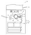
はじめに、本発明の実施形態であるトナー補給装置20を備える画像形成装置10について説明する。図1は、画像形成装置10の構成を示す模式図である。画像形成装置10は、電子写真方式によって、記録用紙などの記録媒体の表面に画像を形成して、印刷物を得る装置である。画像形成装置10は、記録媒体を供給する記録媒体供給部50と、原稿などから画像情報を読み取るスキャナ43と、スキャナ43が読み取った画像情報や画像形成装置10の外部の装置から入力された画像情報に基づいて、供給された記録媒体に画像を形成する電子写真プロセス部60とを備える。電子写真プロセス部60は、感光体ドラム44と、帯電部45と、露光ユニット46と、現像ユニット70と、転写部48と、クリーニング部49と、定着ユニット51とを含む。  First, theimage forming apparatus 10 including thetoner supply device 20 according to the embodiment of the present invention will be described. FIG. 1 is a schematic diagram illustrating a configuration of theimage forming apparatus 10. Theimage forming apparatus 10 is an apparatus that obtains a printed matter by forming an image on the surface of a recording medium such as recording paper by an electrophotographic method. Theimage forming apparatus 10 includes a recordingmedium supply unit 50 that supplies a recording medium, ascanner 43 that reads image information from a document, image information read by thescanner 43, and an image input from an apparatus outside theimage forming apparatus 10. And anelectrophotographic process unit 60 for forming an image on the supplied recording medium based on the information. Theelectrophotographic process unit 60 includes aphotosensitive drum 44, acharging unit 45, anexposure unit 46, a developingunit 70, atransfer unit 48, acleaning unit 49, and afixing unit 51.

感光体ドラム44は、円筒状や円柱状の導電性基体と、この導電性基体の表面に形成される感光層とを含み、図示しない回転駆動源によって、導電性基体の軸線回りに回転可能に設けられる。導電性基体は、たとえばアルミニウムから形成される。感光層は、光を照射されることで導電性を示す材料であり、たとえば有機感光層が用いられる。有機感光層は、電荷発生物質を含む電荷発生層と電荷輸送物質を含む電荷輸送層とが積層されたものであってもよいし、電荷発生物質と電荷輸送物質とを1つの層に含むものであってもよい。  Thephotosensitive drum 44 includes a cylindrical or columnar conductive substrate and a photosensitive layer formed on the surface of the conductive substrate, and can be rotated around the axis of the conductive substrate by a rotation driving source (not shown). Provided. The conductive substrate is made of aluminum, for example. The photosensitive layer is a material that exhibits conductivity when irradiated with light. For example, an organic photosensitive layer is used. The organic photosensitive layer may be a laminate of a charge generation layer containing a charge generation material and a charge transport layer containing a charge transport material, or a layer containing the charge generation material and the charge transport material in one layer. It may be.

帯電部45は、感光体ドラム44の表面を所定の極性および電位に帯電させる装置である。帯電部45としては、ブラシ型帯電装置、ローラ型帯電装置、コロナ放電装置、イオン発生装置などを用いることができ、本実施形態では、たとえば、ローラ型帯電装置が用いられる。  Thecharging unit 45 is a device that charges the surface of thephotosensitive drum 44 to a predetermined polarity and potential. As thecharging unit 45, a brush-type charging device, a roller-type charging device, a corona discharge device, an ion generation device, or the like can be used. In this embodiment, for example, a roller-type charging device is used.

露光ユニット46は、レーザ光を出射する装置であり、露光ユニット46から出射された光は、帯電部45と現像ユニット70との間を通過して感光体ドラム44の表面に照射される。帯電状態にある感光体ドラム44の表面にレーザ光が照射されることによって、その表面に、画像情報に対応する静電潜像が形成される。露光ユニット46としては、たとえば、レーザ照射部および複数の反射ミラーを備えるレーザスキャニングユニット(LSU)を用いることができる。また、露光ユニット46としては、LED(Light Emitting Diode)アレイ、液晶シャッタと光源とを適宜組み合わせたユニットなどを用いてもよい。  Theexposure unit 46 is a device that emits laser light, and the light emitted from theexposure unit 46 passes between thecharging unit 45 and the developingunit 70 and is irradiated onto the surface of thephotosensitive drum 44. By irradiating the surface of thephotosensitive drum 44 in a charged state with laser light, an electrostatic latent image corresponding to image information is formed on the surface. As theexposure unit 46, for example, a laser scanning unit (LSU) including a laser irradiation unit and a plurality of reflection mirrors can be used. Further, as theexposure unit 46, an LED (Light Emitting Diode) array, a unit in which a liquid crystal shutter and a light source are appropriately combined, or the like may be used.

現像ユニット70は、トナー補給装置20と、トナーホッパ13と、現像装置47とを含む。トナー補給装置20は、トナーホッパ13および現像装置47よりも鉛直方向上方(以下では、「鉛直方向上方Y1」と称し、これとは反対の方向を、「鉛直方向下方Y2」と称し、2つの方向を合わせて、「鉛直方向Y」と称する)に配置され、未使用のトナーを収容する。トナー補給装置20は、画像形成装置10が備える図示しない回転駆動源に接続される回転型のトナー補給装置であり、現像装置47内のトナーが消費されて少なくなると、未使用のトナーをトナーホッパ13へ供給する。トナー補給装置20の詳細については後述する。  The developingunit 70 includes atoner replenishing device 20, atoner hopper 13, and a developingdevice 47. Thetoner replenishing device 20 is vertically above thetoner hopper 13 and the developing device 47 (hereinafter, referred to as “vertical upward Y1”, and the opposite direction is referred to as “vertical downward Y2”. And is referred to as “vertical direction Y”) and stores unused toner. Thetoner replenishing device 20 is a rotary toner replenishing device connected to a rotation driving source (not shown) provided in theimage forming apparatus 10. When the toner in the developingdevice 47 is consumed and reduced, unused toner is removed from thetoner hopper 13. To supply. Details of thetoner supply device 20 will be described later.

トナーホッパ13は、トナー補給装置20の鉛直方向下方Y2において、現像装置47に隣接して設けられる。トナーホッパ13は、トナー補給装置20から供給されたトナーを攪拌して、現像装置47へ供給する。  Thetoner hopper 13 is provided adjacent to the developingdevice 47 in the vertical lower portion Y2 of thetoner supply device 20. Thetoner hopper 13 agitates the toner supplied from thetoner replenishing device 20 and supplies it to the developingdevice 47.

現像装置47は、感光体ドラム44上に形成された静電潜像をトナーによって現像することで、感光体ドラム44上にトナー像を形成する装置である。現像装置47は、現像槽、現像ローラ、搬送スクリュー、およびトナー濃度検知センサを備える。現像槽は、その内部空間にトナーを収容する。現像槽内には、現像ローラおよび搬送スクリューが、回転可能に支持される。現像槽は、感光体ドラム44に臨む位置に開口部が形成され、この開口部を挟んで感光体ドラム44に対向する位置に、現像ローラが設けられる。  The developingdevice 47 is a device that forms a toner image on thephotosensitive drum 44 by developing the electrostatic latent image formed on thephotosensitive drum 44 with toner. The developingdevice 47 includes a developing tank, a developing roller, a conveying screw, and a toner concentration detection sensor. The developing tank contains toner in its internal space. A developing roller and a transport screw are rotatably supported in the developing tank. In the developing tank, an opening is formed at a position facing thephotosensitive drum 44, and a developing roller is provided at a position facing thephotosensitive drum 44 across the opening.

現像ローラは、感光体ドラム44との最近接部において感光体ドラム44表面の静電潜像にトナーを供給する部材である。トナーの供給のときには、現像ローラ表面に、トナーの帯電電位とは逆極性の電位が現像バイアス電圧(現像バイアス)として印加される。これによって、現像ローラ表面のトナーが静電潜像に円滑に供給される。現像バイアスの値を変更することによって、静電潜像に供給されるトナー量(トナー付着量)を制御することができる。  The developing roller is a member that supplies toner to the electrostatic latent image on the surface of thephotosensitive drum 44 at a portion closest to thephotosensitive drum 44. When supplying toner, a potential having a polarity opposite to the charging potential of the toner is applied to the surface of the developing roller as a developing bias voltage (developing bias). As a result, the toner on the surface of the developing roller is smoothly supplied to the electrostatic latent image. By changing the value of the developing bias, the amount of toner (toner adhesion amount) supplied to the electrostatic latent image can be controlled.

搬送スクリューは、現像ローラ周辺にトナーを供給する部材である。搬送スクリューによって、トナーは攪拌搬送されて、帯電した状態で現像ローラに供給される。  The conveying screw is a member that supplies toner around the developing roller. The toner is agitated and conveyed by the conveying screw and is supplied to the developing roller in a charged state.

トナー濃度検知センサは、現像槽の底面に設けられる。トナー濃度検知センサは、現像槽中のトナー濃度を検知する。トナー濃度検知センサとしては、一般的なトナー濃度検知センサを使用でき、たとえば、透過光検知センサ、反射光検知センサ、透磁率検知センサなどが挙げられる。これらの中でも、透磁率検知センサが好ましい。  The toner concentration detection sensor is provided on the bottom surface of the developing tank. The toner concentration detection sensor detects the toner concentration in the developing tank. As the toner concentration detection sensor, a general toner concentration detection sensor can be used, and examples thereof include a transmitted light detection sensor, a reflected light detection sensor, and a magnetic permeability detection sensor. Among these, a magnetic permeability detection sensor is preferable.

トナー濃度検知センサは、トナー濃度制御部に電気的に接続される。トナー濃度制御部は、トナー濃度検知センサによるトナー濃度値が所定の設定値よりも低くなると、トナー補給装置20に接続される回転駆動源が作動し、トナー補給装置20内のトナーがトナーホッパ13へ供給される。  The toner concentration detection sensor is electrically connected to the toner concentration control unit. When the toner concentration value detected by the toner concentration detection sensor becomes lower than a predetermined set value, the toner concentration control unit operates a rotation drive source connected to thetoner replenishing device 20 and the toner in thetoner replenishing device 20 is transferred to thetoner hopper 13. Supplied.

転写部48は、感光体ドラム44の表面に圧接するローラ部材であり、図示しない回転駆動源によって軸線回りに回転可能に設けられる。感光体ドラム44上に担持されて搬送されるトナー像は、転写部48と感光体ドラム44との圧接部において、後述する記録媒体供給部50から供給される記録媒体に転写される。  Thetransfer unit 48 is a roller member that comes into pressure contact with the surface of thephotosensitive drum 44 and is provided so as to be rotatable about an axis by a rotation drive source (not shown). The toner image carried and conveyed on thephotosensitive drum 44 is transferred to a recording medium supplied from a recordingmedium supply unit 50 described later at a pressure contact portion between thetransfer unit 48 and thephotosensitive drum 44.

クリーニング部49は、感光体ドラム44から記録媒体へトナー像が転写された後に、感光体ドラム44の表面に残留するトナーや転写の際に付着した紙粉などを除去し、感光体ドラム44の表面を清浄化する部材である。クリーニング部49としては、たとえば、トナーを掻き取るための板状部材と、掻き取ったトナーを回収する容器状部材とが用いられる。  After the toner image is transferred from thephotoconductive drum 44 to the recording medium, thecleaning unit 49 removes toner remaining on the surface of thephotoconductive drum 44 and paper dust adhering to the transfer. It is a member that cleans the surface. As thecleaning unit 49, for example, a plate-like member for scraping off the toner and a container-like member for collecting the scraped toner are used.

記録媒体供給部50は、記録媒体を収容する収容部と、記録媒体を搬送する搬送ローラとを含む。収容部に収容される記録媒体は、搬送ローラによって、感光体ドラム44と転写部48との圧接部に送給され、トナー像が転写された後、定着ユニット51に送給される。記録媒体としては、普通紙、カラーコピー用紙、オーバーヘッドプロジェクタ用シート、葉書などがある。  The recordingmedium supply unit 50 includes a storage unit that stores the recording medium and a conveyance roller that conveys the recording medium. The recording medium accommodated in the accommodating portion is fed to the press-contact portion between thephotosensitive drum 44 and thetransfer portion 48 by the conveying roller, and is transferred to the fixingunit 51 after the toner image is transferred. Examples of the recording medium include plain paper, color copy paper, overhead projector sheet, and postcard.

定着ユニット51は、加熱ローラおよび加圧ローラを含む。加熱ローラは、所定の定着温度となるように制御される。加圧ローラは、加熱ローラに圧接するローラである。加熱ローラは、加圧ローラとともに記録媒体を加熱しながら挟持することにより、トナー像を構成するトナーを溶融させて記録媒体上に定着させる。トナー像が定着した記録媒体は、画像形成装置10の外部に搬送され、画像形成動作が完了する。  The fixingunit 51 includes a heating roller and a pressure roller. The heating roller is controlled to have a predetermined fixing temperature. The pressure roller is a roller in pressure contact with the heating roller. The heating roller holds the recording medium together with the pressure roller while heating, thereby melting the toner constituting the toner image and fixing it on the recording medium. The recording medium on which the toner image is fixed is conveyed to the outside of theimage forming apparatus 10 and the image forming operation is completed.

次に、トナー補給装置20について詳細に説明する。図2は、トナー補給装置20の構成を示す図である。図3は、トナー補給装置20が備える補給装置本体部21の側面を示す図である。図4は、補給装置本体部21のうち、押込み部215を除いたときの補給装置本体部21の側面を示す図である。図5は、押込み部215を除いたときの補給装置本体部21の分解斜視図である。図6は、図3に示す補給装置本体部21を、後述する中心軸線Sを通り、鉛直方向Yに延びる平面で切断したときの断面図である。Next, thetoner replenishing device 20 will be described in detail. FIG. 2 is a diagram illustrating a configuration of thetoner supply device 20. FIG. 3 is a diagram illustrating a side surface of the replenishing devicemain body 21 provided in thetoner replenishing device 20. FIG. 4 is a view illustrating a side surface of the replenishing devicemain body 21 when the pushingportion 215 is removed from the replenishing devicemain body 21. FIG. 5 is an exploded perspective view of the replenishing devicemain body 21 when the pushingportion 215 is removed. FIG. 6 is a cross-sectional view of the replenishing devicemain body 21 shown in FIG. 3 taken along a plane that passes through a center axis S1 described later and extends in the vertical direction Y.

トナー補給装置20は、トナー袋211aとトナー排出部211bとを含むトナー収容部211、連結部212、支持部材213、支持台214、および押込み部215を有する補給装置本体部21と、駆動源側連結部221、回転軸部材222、ギア223、および押しばね224を有する駆動力伝達部22と、2つのガイド部材231を有する筺体23とを備える。  Thetoner supply device 20 includes atoner storage unit 211 including atoner bag 211a and atoner discharge unit 211b, a connectingunit 212, asupport member 213, asupport base 214, and a pushingunit 215, and a drive source side. A drivingforce transmission unit 22 having a connectingpart 221, arotating shaft member 222, agear 223, and apressing spring 224, and ahousing 23 having twoguide members 231 are provided.

筺体23は、補給装置本体部21の一部、駆動源側連結部221、回転軸部材222の一部、および押しばね224を収容する内部空間が形成され、鉛直方向下方Y2の端部が開放される箱状部材である。ギア223は、筺体23の外側に配置される。筺体23の、所定の一方向(以下では、X1方向と称する)端部となる壁部23aには、第1貫通孔23aaが形成され、X1方向とは反対の方向(以下では、X2方向と称する)の端部となる壁部23bには、第2貫通孔23baが形成される。第1貫通孔23aaは、補給装置本体部21が挿通可能な大きさの孔であり、トナー補給装置20の使用時には、補給装置本体部21のX1方向端部が挿通されている。第2貫通孔23baは、回転軸部材222が挿通される孔であり、第2貫通孔23baにおいて、回転軸部材222の周りには、図示しない軸受が設けられる。  Thehousing 23 is formed with an internal space that accommodates a part of the replenishing devicemain body 21, a drive sourceside coupling part 221, a part of therotary shaft member 222, and thepressing spring 224, and an end part of the lower Y <b> 2 in the vertical direction is open. It is a box-shaped member. Thegear 223 is disposed outside thehousing 23. A first through hole 23aa is formed in awall portion 23a which is an end portion of thecasing 23 in a predetermined direction (hereinafter referred to as X1 direction), and a direction opposite to the X1 direction (hereinafter referred to as X2 direction). The second through hole 23ba is formed in thewall portion 23b which is an end portion of the second through hole 23ba. The first through hole 23aa is a hole having a size that allows the replenishing devicemain body 21 to be inserted, and the X1 direction end of the replenishing devicemain body 21 is inserted when thetoner replenishing device 20 is used. The second through hole 23ba is a hole through which therotary shaft member 222 is inserted, and a bearing (not shown) is provided around therotary shaft member 222 in the second through hole 23ba.

トナー収容部211は、トナー袋211aとトナー排出部211bとによって内部空間を形成する部材であり、その内部空間にトナーを収容する。トナー袋211aは、1つの口を有する袋である。トナー排出部211bは、一端が開口する有底円筒状部材であり、トナー排出部211bの中心軸線Sは、X1方向およびX2方向に延びる。トナー袋211aおよびトナー排出部211bは、互いの口を塞ぐように接続される。Thetoner storage unit 211 is a member that forms an internal space by thetoner bag 211a and thetoner discharge unit 211b, and stores toner in the internal space. Thetoner bag 211a is a bag having one mouth.Toner discharging portion 211b is a bottomed cylindrical member having one end open, the central axis linesS 1 of thetoner discharge portion 211b extends in the X1 direction and the X2 direction. Thetoner bag 211a and thetoner discharge portion 211b are connected so as to close each other's mouth.

トナー袋211aの外表面には、可撓性を有するトナー袋保持部材211cが設けられる。トナー袋保持部材211cによって、トナー袋211aの形状は、中心軸線S方向に延びる略有底円筒状に保持される。トナー袋保持部材211cは、中心軸線Sを中心として、トナー袋211aの外表面を取り巻く螺旋状に形成され、該外表面に固定される。A flexible tonerbag holding member 211c is provided on the outer surface of thetoner bag 211a. The tonerbag holding member 211c, the shape of thetoner bag 211a is held in a substantially bottomed cylindrical shape extending in the center axis lines S1 direction. Tonerbag holding member 211c is about the central axis line S1, is formed in a spiral shape surrounding the outer surface of thetoner bag 211a, it is secured to the outer surface.

トナー排出部211bの側壁部には、トナーを外部に排出するためのトナー排出口211baが形成される。トナー排出口211baの形状はたとえば正方形状であり、この正方形状の一辺の長さはたとえば10mm〜25mmである。トナー排出部211bの底壁部には、連結部212が形成される。  A toner discharge port 211ba for discharging the toner to the outside is formed in the side wall portion of thetoner discharge portion 211b. The shape of the toner discharge port 211ba is, for example, a square shape, and the length of one side of the square shape is, for example, 10 mm to 25 mm. A connectingportion 212 is formed on the bottom wall portion of thetoner discharge portion 211b.

連結部212は、トナー排出部211bの底壁部の外表面、すなわち、トナー排出部211bの底面に形成される。連結部212は、X2方向に突出する凸部であり、この凸部は、X1方向に見たときの形状が十字状である。  The connectingportion 212 is formed on the outer surface of the bottom wall portion of thetoner discharge portion 211b, that is, on the bottom surface of thetoner discharge portion 211b. The connectingportion 212 is a convex portion protruding in the X2 direction, and the shape of the convex portion when viewed in the X1 direction is a cross shape.

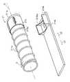
押込み部215は、筒体215aと、エアポンプ215bと、ピストン215cと、蛇腹筒部215dとを含む。筒体215aは、両端が開口する円筒状部材であり、その軸線は中心軸線Sと一致する。筒体215aは、軸線方向一端側において、該筒体215aから離間して、エアポンプ215bおよび蛇腹筒部215dが設けられる。筒体215aの軸線方向他端部は、トナー排出部211bに対して、着脱可能に接続され、筒体215aとトナー排出部211bとによって内部空間が形成される。この内部空間には、トナー袋211aが収容される。筒体215aは、トナー収容部211と接続された状態で、後述するようにトナー収容部211が回転するときに、該トナー収容部211とともに回転する。The pushingportion 215 includes acylindrical body 215a, anair pump 215b, apiston 215c, and a bellowscylindrical portion 215d. Thecylindrical body 215a is a cylindrical member whose both ends are opened, its axis coincides with the central axis line S1. Thecylindrical body 215a is provided with anair pump 215b and a bellowscylindrical portion 215d at one end side in the axial direction, spaced from thecylindrical body 215a. The other end in the axial direction of thecylinder 215a is detachably connected to thetoner discharge portion 211b, and an internal space is formed by thecylinder 215a and thetoner discharge portion 211b. Atoner bag 211a is accommodated in this internal space. Thecylindrical body 215a rotates together with thetoner container 211 when thetoner container 211 rotates as will be described later in a state of being connected to thetoner container 211.

ピストン215cは、トナー袋211aよりも筒体215aの軸線方向一端側において、該筒体215aの内表面に支持される。よって、ピストン215cは、筒体215aが回転するときに、該筒体215aとともに回転する。ピストン215cは、筒体215aとトナー排出部211bとによって形成される内部空間を該トナー排出部211bに向かって移動することで、トナー袋211aをトナー排出部211bへ押し込む部材である。これに対して、本発明の他の実施形態としては、筒体215a内に空気を送り込み、トナー袋211aを空気によって押し込むように構成してもよい。  Thepiston 215c is supported on the inner surface of thecylindrical body 215a on one end side in the axial direction of thecylindrical body 215a with respect to thetoner bag 211a. Therefore, thepiston 215c rotates together with thecylinder 215a when thecylinder 215a rotates. Thepiston 215c is a member that pushes thetoner bag 211a into thetoner discharge portion 211b by moving toward thetoner discharge portion 211b in an internal space formed by thecylindrical body 215a and thetoner discharge portion 211b. On the other hand, as another embodiment of the present invention, air may be sent into thecylinder 215a and thetoner bag 211a may be pushed in by air.

蛇腹筒部215dは、空気が送り込まれたときに、ピストン215cをトナー排出部211bに向かって移動させるように伸びる部材であり、その軸線は中心軸線Sと一致する。蛇腹筒部215dは、その軸線方向一端部に1つの開口部を有し、この開口部にエアポンプ215bが接続される。蛇腹筒部215dの軸線方向一端部の位置は、筒体215aに対して固定位置である。また、蛇腹筒部215dは、その軸線方向他端部に、ピストン215cが接続される。蛇腹筒部215dの軸線方向他端部とピストン215cとは、ともに筒体215aの軸線方向にスライド移動可能に接続され、かつ、ピストン215cが回転するときに蛇腹筒部215dが回転しないように接続される。このように接続するためには、たとえば、図6に示すように、蛇腹筒部215dの軸線方向他端部の凸部を、ピストン215cの凹部に嵌合させ、この凸部または凹部の少なくとも一方に、摩擦抵抗を低くするためのオイルを塗布または含浸させればよい。Bellows tube portion 215d, when the air is fed, a member extending so as to move toward thepiston 215c to thetoner discharge portion 211b, its axis coincides with the central axis line S1. The bellowscylinder portion 215d has one opening at one end in the axial direction thereof, and theair pump 215b is connected to the opening. The position of the one end portion in the axial direction of thebellows tube portion 215d is a fixed position with respect to thetube body 215a. Further, thebellows tube portion 215d is connected to thepiston 215c at the other axial end portion. The other end in the axial direction of thebellows cylinder portion 215d and thepiston 215c are both slidably connected in the axial direction of thecylinder 215a, and are connected so that thebellows cylinder portion 215d does not rotate when thepiston 215c rotates. Is done. In order to connect in this way, for example, as shown in FIG. 6, the convex portion at the other end in the axial direction of thebellows cylinder portion 215d is fitted into the concave portion of thepiston 215c, and at least one of the convex portion or the concave portion is provided. Further, an oil for reducing the frictional resistance may be applied or impregnated.

エアポンプ215bは、蛇腹筒部215dの内部に空気を送り込んだり、内部の空気を吸い込んだりする。エアポンプ215bによって蛇腹筒部215dの内部に空気が送り込まれるとき、蛇腹筒部215dは軸線方向に伸び、ピストン215cは筒体215aの軸線方向他端部に向かって移動する。エアポンプ215bによって蛇腹筒部215dの内部の空気が吸い込まれるとき、蛇腹筒部215dは軸線方向に縮み、ピストン215cは筒体215aの軸線方向一端部に向かって移動する。  Theair pump 215b sends air into thebellows cylinder portion 215d or sucks air inside. When air is sent into thebellows cylinder 215d by theair pump 215b, thebellows cylinder 215d extends in the axial direction, and thepiston 215c moves toward the other axial end of thecylinder 215a. When the air inside thebellows cylinder portion 215d is sucked by theair pump 215b, thebellows cylinder portion 215d contracts in the axial direction, and thepiston 215c moves toward one end portion in the axial direction of thecylinder body 215a.

このように構成される押込み部215は、トナー収容部211内のトナーが無くなったときに、トナー袋211aをトナー排出部211b内へ押し込むことで、トナー収容部211の体積を小さくする。トナー収容部211は筒体215aから取り外すことが可能であり、トナー収容部211の交換の際、トナーが無くなったトナー収容部211の体積を小さくして該トナー収容部211を廃棄することで、ごみの体積を小さくすることができる。  The pushingportion 215 configured as described above reduces the volume of thetoner containing portion 211 by pushing thetoner bag 211a into thetoner discharging portion 211b when the toner in thetoner containing portion 211 runs out. Thetoner container 211 can be removed from thecylindrical body 215a. When thetoner container 211 is replaced, thetoner container 211 can be removed by reducing the volume of thetoner container 211 that has run out of toner. The volume of garbage can be reduced.

支持部材213は、トナー収容部211を、中心軸線Sを回転軸線として回転可能に支持する、トナー収容部211よりも径が大きな円筒状の部材であり、支持台214に着脱可能に構成される。中心軸線S方向における支持部材213の長さは、100mm〜150mmであり、支持部材213は、中心軸線S方向において、主に、トナー排出部211bを支持する位置に設けられる。トナー補給装置20の使用時には、支持部材213は支持台214に装着されている。支持部材213には、その鉛直方向Y下部に、トナー排出口211baと同じ形状・大きさの第1連通口213aが形成される。第1連通口213aは、トナー収容部211が回転することでトナー排出口211baが鉛直方向下方Y2に位置したときに、トナー排出口211baと連通するように形成される。Thesupport member 213 is a cylindrical member having a diameter larger than that of thetoner storage portion 211 that rotatably supports thetoner storage portion 211 with the central axis S1 as the rotation axis, and is configured to be detachable from thesupport base 214. The The length of thesupport member 213 in the central axis linesS 1 direction is 100Mm~150mm,support member 213 is in the center axis linesS 1 direction, mainly provided at a position for supporting thetoner discharge portion 211b. When thetoner supply device 20 is used, thesupport member 213 is mounted on thesupport base 214. Afirst communication port 213a having the same shape and size as the toner discharge port 211ba is formed in thesupport member 213 in the lower portion in the vertical direction Y. Thefirst communication port 213a is formed so as to communicate with the toner discharge port 211ba when the toner discharge port 211ba is positioned in the lower vertical direction Y2 due to the rotation of thetoner container 211.

支持台214は、支持部材213が装着可能に構成される装着部214aと、装着部214aの鉛直方向Y下部に固定される矩形平板状の台座部214bとを含む。台座部214bは、中心軸線S方向に長く延び、トナーホッパ13の鉛直方向上方Y1に配置される。台座部214bには、第1連通口213aと同じ形状・大きさの第2連通口214baが形成される。第2連通口214baは、支持台214に支持部材213が装着されているときに、第1連通口213aと連通するように形成される。Thesupport base 214 includes a mountingportion 214a configured so that thesupport member 213 can be mounted, and a rectangular flat plate-like base portion 214b fixed to a lower portion in the vertical direction Y of the mountingportion 214a.Pedestal 214b is elongated in the central axis linesS 1 direction, it is arranged vertically above Y1 of thetoner hopper 13. A second communication port 214ba having the same shape and size as thefirst communication port 213a is formed in thebase portion 214b. The second communication port 214ba is formed to communicate with thefirst communication port 213a when thesupport member 213 is mounted on thesupport base 214.

ギア223は、画像形成装置10が備える図示しない回転駆動源と係合し、3rpm〜6rpmで回転する。回転軸部材222は、円柱状の部材であり、ギア223が回転するときに該円柱の中心軸線まわりに回転するように、ギア223に接続される。回転軸部材222の回転方向は、中心軸線まわりの2つの方向のうち、図3などに示す回転方向Gである。また、この円柱の中心軸線は、中心軸線Sと一致する。Thegear 223 engages with a rotation drive source (not shown) included in theimage forming apparatus 10 and rotates at 3 rpm to 6 rpm. Therotation shaft member 222 is a cylindrical member, and is connected to thegear 223 so as to rotate around the central axis of the cylinder when thegear 223 rotates. The rotation direction of therotation shaft member 222 is the rotation direction G shown in FIG. 3 or the like out of two directions around the central axis. The center axis of this cylinder coincides with the center axis S1.

駆動源側連結部221は、円盤状の部材であり、一方の主面側に、X2方向に退避する凹部を有し、この凹部は、X2方向に見たときの形状が十字状である。トナー補給装置20の使用時には、この凹部は、連結部212の凸部と嵌合する。駆動源側連結部221の他方の主面は、回転軸部材222に固定され、回転軸部材222が回転するのに伴って、駆動源側連結部221も回転する。  The drive sourceside connecting portion 221 is a disk-shaped member, and has a concave portion that retreats in the X2 direction on one main surface side, and this concave portion has a cross shape when viewed in the X2 direction. When thetoner replenishing device 20 is used, the concave portion is fitted with the convex portion of the connectingportion 212. The other main surface of the drive sourceside connecting portion 221 is fixed to therotary shaft member 222, and the drive sourceside connecting portion 221 also rotates as therotary shaft member 222 rotates.

押しばね224は、コイルスプリングからなり、壁部23bと駆動源側連結部221との間の位置に設けられる。この位置において、押しばね224は、回転軸部材222が挿通される。押しばね224は、回転軸部材222および駆動源側連結部221の回転を阻害することなく、駆動源側連結部221が壁部23bから離間するように、X1方向へのばね力を付与する。これによって、連結部212の凸部と駆動源側連結部221の凹部とが嵌合する際に、駆動源側連結部221が連結部212によって押されて、駆動源側連結部221に固定される回転軸部材222、および、回転軸部材222に固定されるギア223が、X2方向に移動してしまうのを防いでいる。  Thepush spring 224 is formed of a coil spring and is provided at a position between thewall portion 23b and the drive sourceside connecting portion 221. At this position, therotary shaft member 222 is inserted through thepush spring 224. Thepush spring 224 applies a spring force in the X1 direction so that the drive sourceside coupling portion 221 is separated from thewall portion 23b without hindering the rotation of therotation shaft member 222 and the drive sourceside coupling portion 221. Accordingly, when the convex portion of the connectingportion 212 and the concave portion of the driving sourceside connecting portion 221 are fitted, the driving sourceside connecting portion 221 is pushed by the connectingportion 212 and is fixed to the driving sourceside connecting portion 221. Therotation shaft member 222 and thegear 223 fixed to therotation shaft member 222 are prevented from moving in the X2 direction.

2つのガイド部材231は、補給装置本体部21、より詳細には、支持台214の台座部214bを、X1方向およびX2方向に移動可能に支持する。2つのガイド部材231は、壁部23bから、第1貫通孔23aaを通って、筺体23の外部まで、X1方向に延びて設けられる。  The twoguide members 231 support the supply devicemain body 21, more specifically, thepedestal 214b of thesupport base 214 so as to be movable in the X1 direction and the X2 direction. The twoguide members 231 are provided so as to extend in the X1 direction from thewall portion 23b through the first through hole 23aa to the outside of thehousing 23.

上述したように、第1貫通孔23aaは、補給装置本体部21が挿通可能な大きさであり、トナー補給装置20の非使用時には、補給装置本体部21をX1方向に引くことで、連結部212と駆動源側連結部221との嵌合状態を解除し、駆動力伝達部22から補給装置本体部21を脱離させて、補給装置本体部21を、第1貫通孔23aaから引き出すことができる。補給装置本体部21を引き出した後は、支持台214から、トナー収容部211および支持部材213を取り外して、新たなトナー収容部211に交換することができる。トナー収容部211の交換後は、補給装置本体部21をX2方向に押すことで、補給装置本体部21を押し入れることができる。このとき、連結部212と駆動源側連結部221とが嵌合して、トナー収容部211が駆動源側連結部221に装着され、トナー補給装置20が使用可能となる。  As described above, the first through hole 23aa has a size that allows the replenishing devicemain body 21 to be inserted. When thetoner replenishing device 20 is not used, the first through-hole 23aa is pulled in the X1 direction to connect the connecting portion. The fitting state between the 212 and the drive sourceside connecting portion 221 is released, the replenishing devicemain body portion 21 is detached from the drivingforce transmitting portion 22, and the replenishing devicemain body portion 21 is pulled out from the first through hole 23aa. it can. After the replenishing devicemain body 21 is pulled out, thetoner storage portion 211 and thesupport member 213 can be removed from thesupport base 214 and replaced with a newtoner storage portion 211. After the replacement of thetoner container 211, the replenishing devicemain body 21 can be pushed in by pushing the replenishing devicemain body 21 in the X2 direction. At this time, the connectingportion 212 and the driving sourceside connecting portion 221 are fitted, and thetoner storage portion 211 is attached to the driving sourceside connecting portion 221 so that thetoner replenishing device 20 can be used.

以上のように構成されるトナー補給装置20によれば、補給装置本体部21の連結部212と、画像形成装置10が備える図示しない回転駆動源とが、駆動力伝達部22を介して連結される。これによって、連結部212が形成されるトナー収容部211は、中心軸線Sまわりに回転する。トナー収容部211が回転すると、トナー排出口211baが鉛直方向下方Y2に位置したときに、トナー排出口211ba、第1連通口213a、および第2連通口214baが連通し、このときに、トナー収容部211に収容されるトナーは、トナー排出口211ba、第1連通口213a、および第2連通口214baを経て、トナーホッパ13へ供給され、現像装置47にトナーが補給される。According to thetoner replenishing device 20 configured as described above, the connectingportion 212 of the replenishing devicemain body 21 and the rotation drive source (not shown) included in theimage forming apparatus 10 are connected via the drivingforce transmitting portion 22. The Thus, thetoner accommodating portion 211connection portion 212 is formed to rotate about axis S around1. When thetoner container 211 rotates, the toner discharge port 211ba, thefirst communication port 213a, and the second communication port 214ba communicate with each other when the toner discharge port 211ba is positioned in the lower vertical direction Y2. The toner stored in thesection 211 is supplied to thetoner hopper 13 through the toner discharge port 211ba, thefirst communication port 213a, and the second communication port 214ba, and the developingdevice 47 is replenished with toner.

さらに、上記のようにトナー収容部211を回転駆動しても現像装置47内のトナー濃度が上昇しない場合には、画像形成装置10はトナー収容部211内のトナーが無くなったと判断し、トナー収容部211を回転駆動しながら、エアポンプ215bを駆動する。このとき、筒体215aおよび筒体215a内のピストン215cは、トナー収容部211とともに回転方向Gに回転しているが、エアポンプ215bおよび蛇腹筒部215dは回転せず、エアポンプ215bによって空気が送り込まれた蛇腹筒部215dは、回転中のピストン215cをトナー排出部211bへ向かって移動させる。これによって、空になったトナー袋211aがトナー排出部211b内に押し込まれる。図7に、トナー袋211aが押し込まれる様子を示す。図7のようにトナー袋211aが押し込まれた後、ユーザは、補給装置本体部21をX1方向に引き出して、トナー収容部211を新たなトナー収容部211へと交換することができるとともに、廃棄するトナー収容部211の体積は小さくなっているので、ごみの体積を小さくすることができる。なお、新たなトナー収容部211を取り付ける前には、エアポンプ215bによって、蛇腹筒部215d内の空気を吸引して、該蛇腹筒部215dを縮ませ、ピストン215cを筒体215aの軸線方向一端部に移動させておく。  Further, if the toner density in the developingdevice 47 does not increase even when thetoner storage unit 211 is rotationally driven as described above, theimage forming apparatus 10 determines that the toner in thetoner storage unit 211 has run out, and the toner storage unit Theair pump 215b is driven while rotating thepart 211. At this time, thecylinder 215a and thepiston 215c in thecylinder 215a rotate in the rotation direction G together with thetoner container 211, but theair pump 215b and thebellows cylinder 215d do not rotate, and air is fed by theair pump 215b. Thebellows cylinder portion 215d moves therotating piston 215c toward thetoner discharge portion 211b. As a result, theempty toner bag 211a is pushed into thetoner discharge portion 211b. FIG. 7 shows how thetoner bag 211a is pushed. After thetoner bag 211 a is pushed in as shown in FIG. 7, the user can pull out the replenishing devicemain body 21 in the X1 direction to replace thetoner storage unit 211 with a newtoner storage unit 211 and discard it. Since the volume of thetoner container 211 to be reduced is reduced, the volume of dust can be reduced. Before attaching anew toner container 211, theair pump 215b sucks the air in thebellows cylinder 215d to contract thebellows cylinder 215d, and thepiston 215c is connected to one end in the axial direction of thecylinder 215a. Move it to.

本実施形態では、トナー排出部211b内に押し込まれるトナー袋211aの外表面には、螺旋状のトナー袋保持部材211cが固定されているので、トナー袋211aの形状は、図7に示すように、略有底円筒状のまま、その軸線方向の長さが短くなるように変形し、極端に歪な形には変形しない。これによって、トナー袋211a内の残留トナーはトナー排出部211bへ移動し、トナー排出部211bのトナー排出口211baと支持部材213の第1連通口213aとが連通したときに、残留トナーがトナーホッパ13へ移動する。したがって、本実施形態では、トナー収容部211内の残留トナーを無駄なく使用することができる。  In the present embodiment, since the helical tonerbag holding member 211c is fixed to the outer surface of thetoner bag 211a pushed into thetoner discharge portion 211b, the shape of thetoner bag 211a is as shown in FIG. It is deformed so that its length in the axial direction is shortened while maintaining a substantially bottomed cylindrical shape, and does not deform into an extremely distorted shape. As a result, the residual toner in thetoner bag 211a moves to thetoner discharge portion 211b. When the toner discharge port 211ba of thetoner discharge portion 211b and thefirst communication port 213a of thesupport member 213 communicate with each other, the residual toner is transferred to thetoner hopper 13. Move to. Therefore, in this embodiment, the residual toner in thetoner storage unit 211 can be used without waste.

なお、螺旋状のトナー袋保持部材211cは、ピストン215cによって圧縮されると、元に戻ろうとする力が発生する。トナー袋保持部材211cが元に戻ると、トナー袋保持部材211cが固定されたトナー袋211aの体積は増加してしまう。そこで、筒体215aとトナー収容部211とを分離する際には、図7のようにトナー排出口211baと第1連通口213aとが非連通の状態で、筒体215aとトナー収容部211とを分離するのが好ましい。トナー排出部211bの回転によって、トナー排出口211baと第1連通口213aとは、連通状態・非連通状態を繰り返しているので、トナー排出部211b内の気圧はほぼ大気圧に等しい。したがって、非連通状態において筒体215aとトナー収容部211とを分離すれば、分離後は、大気圧によって、トナー袋211aの体積が増加するのが抑えられ、これによって、トナー袋保持部材211cの元に戻ろうとする力を抑えることができる。その後、接着テープなどでトナー袋211aおよびトナー袋保持部材211cをトナー排出部211bに固定し、支持部材213をトナー収容部211から取り外すことで、トナー袋211aをトナー排出部211b内に押し込んだまま、トナー収容部211を廃棄することができる。  Note that when the helical tonerbag holding member 211c is compressed by thepiston 215c, a force for returning to the original state is generated. When the tonerbag holding member 211c is restored, the volume of thetoner bag 211a to which the tonerbag holding member 211c is fixed increases. Therefore, when separating thecylindrical body 215a and thetoner storage portion 211, thecylindrical body 215a and thetoner storage portion 211 are in a state where the toner discharge port 211ba and thefirst communication port 213a are not in communication as shown in FIG. Is preferably separated. Due to the rotation of thetoner discharge portion 211b, the toner discharge port 211ba and thefirst communication port 213a repeat the communication state / non-communication state, so that the air pressure in thetoner discharge portion 211b is substantially equal to the atmospheric pressure. Therefore, if thecylindrical body 215a and thetoner container 211 are separated in the non-communication state, the volume of thetoner bag 211a is suppressed from being increased by the atmospheric pressure after the separation, whereby the tonerbag holding member 211c The force to return to the original can be suppressed. Thereafter, thetoner bag 211a and the tonerbag holding member 211c are fixed to thetoner discharge portion 211b with an adhesive tape or the like, and thesupport member 213 is removed from thetoner storage portion 211, so that thetoner bag 211a is pushed into thetoner discharge portion 211b. Thetoner container 211 can be discarded.

次に、図6を用いて、トナー袋211a、トナー排出部211b、およびトナー袋保持部材211cの詳細について説明する。トナー排出部211bは、その側壁部の内表面に、第1突起部211bbおよび第2突起部211bcが形成される。第1突起部211bbおよび第2突起部211bcは、中心軸線S方向においてトナー排出口211baの両側に形成され、中心軸線Sに向かって5mm〜10mm程度突出する。第1突起部211bbおよび第2突起部211bcは、中心軸線Sを取り巻く螺旋状に形成され、螺旋の向きは互いに逆方向である。第1突起部211bbは、トナー排出口211baよりもX2方向側に形成され、その螺旋の向きは、トナー排出部211bが回転方向Gに回転するときにトナーをX1方向に搬送する向きである。第2突起部211bcは、トナー排出口211baよりもX1方向側に形成され、その螺旋の向きは、トナー排出部211bが回転方向Gに回転するときにトナーをX2方向に搬送する向きである。Next, details of thetoner bag 211a, thetoner discharge portion 211b, and the tonerbag holding member 211c will be described with reference to FIG. As for thetoner discharge part 211b, the 1st projection part 211bb and the 2nd projection part 211bc are formed in the inner surface of the side wall part. First protrusion 211bb and second protrusions 211bc are formed on both sides of the toner discharge opening 211ba at the center axis linesS 1 direction, it protrudes approximately 5mm~10mm toward the central axis linesS 1. First protrusion 211bb and second protrusions 211bc is formed in a spiral shape around a central axisS 1, the orientation of the helix are mutually opposite. The first protrusion 211bb is formed on the X2 direction side of the toner discharge port 211ba, and the direction of the spiral is a direction in which the toner is conveyed in the X1 direction when thetoner discharge portion 211b rotates in the rotation direction G. The second protrusion 211bc is formed on the X1 direction side of the toner discharge port 211ba, and the direction of the spiral is the direction in which the toner is conveyed in the X2 direction when thetoner discharge portion 211b rotates in the rotation direction G.

トナー排出部211bは、たとえば、ポリエチレン、ポリプロピレン、ポリスチレン、HIPS樹脂(ハイインパクトポリスチレン樹脂)、ABS樹脂(アクリロニトリル−ブタジエン−スチレン共重合合成樹脂)などの材料から形成される。トナー排出部211bの内径Lは、たとえば100mm〜120mmであり、中心軸線S方向の長さLは、たとえば80mm〜100mmである。Thetoner discharge portion 211b is formed of a material such as polyethylene, polypropylene, polystyrene, HIPS resin (high impact polystyrene resin), ABS resin (acrylonitrile-butadiene-styrene copolymer synthetic resin), for example. The inner diameterL 1 of thetoner discharging portion 211b is, for example, a 100Mm~120mm, center axis linesS 1 direction lengthL 2 is, for example, 80Mm~100mm.

トナー袋211aは、その内表面に、中心軸線Sに向かって5mm〜10mm程度突出する第3突起部211aaが形成される。第3突起部211aaは、中心軸線Sを取り巻く螺旋状に形成され、その螺旋の向きは、第2突起部211bcの螺旋の向きと同じ方向である。したがって、第3突起部211aaは、トナー排出部211bが回転方向Gに回転するときにトナーをX2方向に搬送する。Toner bag 211a has on its inner surface, the third protrusions 211aa which projects approximately 5mm~10mm toward the central axis lineS 1 is formed. The third protrusions 211aa is formed in a spiral shape around a central axis S1, the direction of the helix is the same direction as the direction of the helix of the second protrusion 211Bc. Therefore, the third protrusion 211aa conveys the toner in the X2 direction when thetoner discharger 211b rotates in the rotation direction G.

トナー袋211aは、その内表面の一部が上記のように中心軸線Sに向かって突出する代わりに、その外表面の一部が中心軸線Sに向かって凹んでいる。すなわち、トナー袋211aの外側部分には、第3突起部211aaと同じ向きの螺旋状の凹部が形成されている。この螺旋状の凹部には、トナー袋保持部材211cが嵌合し、固定されている。すなわち、トナー袋保持部材211cは、第3突起部211aaに沿って、トナー袋211aを螺旋状に取り巻いて固定される。このトナー袋保持部材211cによって、トナー袋211aは、略有底円筒状に保持され、第3突起部211aaが保持される。Toner bag 211a, a portion of the inner surface, instead of projecting toward the central axis lines S1 as described above, a part of its outer surface is recessed toward the center axis lines S1 thereof. That is, a spiral recess having the same direction as the third protrusion 211aa is formed on the outer portion of thetoner bag 211a. The tonerbag holding member 211c is fitted and fixed in the spiral recess. That is, the tonerbag holding member 211c is fixed by surrounding thetoner bag 211a in a spiral manner along the third protrusion 211aa. Thetoner bag 211a is held in a substantially bottomed cylindrical shape by the tonerbag holding member 211c, and the third protrusion 211aa is held.

トナー袋211aは、たとえば、ポリエチレン、ポリプロピレン、ポリビニルアルコールなどの可撓性材料や、これらから成形される段ボール材から形成される。また、トナー袋211aは、たとえば、厚みLが0.03mm〜0.1mmであり、内径Lが80mm〜100mmであり、中心軸線S方向の長さLが200mm〜250mmである。Thetoner bag 211a is formed of, for example, a flexible material such as polyethylene, polypropylene, or polyvinyl alcohol, or a corrugated cardboard material molded therefrom. Thetoner bag 211a are, for example, the thicknessL 3 is 0.03Mm~0.1Mm, an inner diameter ofL 4 is 80Mm~100mm, the central axis linesS 1 direction lengthL 5 is 200Mm~250mm.

なお、本実施形態では、トナー袋211aはポリエチレンから形成される。トナー袋211aがポリエチレン製である場合、トナーが付着し難いという利点がある。  In the present embodiment, thetoner bag 211a is made of polyethylene. When thetoner bag 211a is made of polyethylene, there is an advantage that the toner hardly adheres.

このように本実施形態では、トナー袋211aが可撓性材料から形成され、トナー排出部211bがトナー袋211aとは別の部材として設けられるので、トナー排出口211baが変形しないようにトナー排出部211bを強固に形成することができ、所定量のトナーを確実に補給することが可能となる。また、トナー排出部211bがトナー袋211aとは別の部材として設けられるので、トナー袋211aを切り離すことでトナー排出部211bを新たなトナー収容部211を製造するために再利用することが可能である。  As described above, in the present embodiment, thetoner bag 211a is formed of a flexible material, and thetoner discharge portion 211b is provided as a separate member from thetoner bag 211a, so that the toner discharge portion 211ba is not deformed. 211b can be formed firmly, and a predetermined amount of toner can be reliably supplied. Further, since thetoner discharge portion 211b is provided as a member different from thetoner bag 211a, thetoner discharge portion 211b can be reused to manufacture a newtoner storage portion 211 by separating the toner bag 211a. is there.

トナー袋保持部材211cは、ポリエチレン、ポリプロピレン、ポリビニルアルコールなどの可撓性材料から形成される。トナー袋保持部材211cは、トナー袋211aへの接着性が高くなるように、トナー袋211aと同じ材料から形成されることが好ましく、本実施形態ではポリエチレン製である。  The tonerbag holding member 211c is formed of a flexible material such as polyethylene, polypropylene, and polyvinyl alcohol. The tonerbag holding member 211c is preferably made of the same material as that of thetoner bag 211a so as to have high adhesion to thetoner bag 211a, and is made of polyethylene in this embodiment.

本実施形態では、トナー袋保持部材211cは、螺旋状に延びる1本の棒状部材である。これに対して、本発明の他の実施形態としては、トナー袋保持部材211cは複数設けられてもよい。  In the present embodiment, the tonerbag holding member 211c is a single rod-like member extending in a spiral shape. On the other hand, as another embodiment of the present invention, a plurality of tonerbag holding members 211c may be provided.

トナー袋保持部材211cは、中心軸線S方向において隣接する一部分同士のピッチLが、たとえば40mm〜50mmである。また、トナー袋保持部材211cの断面の円の直径は、たとえば1mm〜2mmである。Tonerbag holding member 211c, the pitchL 6 between a portion adjacent to each other in the center axis linesS 1 direction, for example, 40Mm~50mm. Further, the diameter of the circle of the cross section of the tonerbag holding member 211c is, for example, 1 mm to 2 mm.

このようなトナー袋保持部材211cがトナー袋211aの外表面に固定されているので、トナー袋211aの第3突起部211aaの形状が保持され、第3突起部211aaによって確実にトナーを搬送することができる。したがって、第3突起部211aaをトナー袋211aと同じ材質で形成することができ、製造が容易になる。  Since the tonerbag holding member 211c is fixed to the outer surface of thetoner bag 211a, the shape of the third protrusion 211aa of thetoner bag 211a is held, and the toner is reliably conveyed by the third protrusion 211aa. Can do. Therefore, the third protrusion 211aa can be formed of the same material as that of thetoner bag 211a, which facilitates manufacture.

上記のようなトナー袋211aおよびトナー袋保持部材211cは、たとえば、円柱の側面に螺旋状の溝が形成された形状の金型を被覆するようにして、トナー袋211aを成形した後、トナー袋211aをその金型から取り外し、トナー袋211a内に空気を送って形状を保った状態で、トナー袋保持部材211cをトナー袋211aの螺旋状の凹部に嵌合および接着することで形成することができる。  For example, thetoner bag 211a and the tonerbag holding member 211c are formed after thetoner bag 211a is formed so as to cover a mold having a spiral groove formed on the side surface of a cylinder. The tonerbag holding member 211c is formed by fitting and adhering to the spiral recess of thetoner bag 211a in a state where the 211a is removed from the mold and air is sent into thetoner bag 211a to keep the shape. it can.

また、本発明の他の実施形態として、有底円筒状の袋の側面に、トナー袋保持部材211cを螺旋状に接着した後、その袋の表と裏とを反転させてトナー袋211aとし、トナー袋保持部材211cをトナー袋211aの内側に配置することで形成してもよい。この場合、トナー袋保持部材211cは、第3突起部211aaとして機能する。  As another embodiment of the present invention, a tonerbag holding member 211c is spirally bonded to the side of a bottomed cylindrical bag, and then the front and back of the bag are reversed to form atoner bag 211a. The tonerbag holding member 211c may be formed inside thetoner bag 211a. In this case, the tonerbag holding member 211c functions as the third protrusion 211aa.

次に、筒体215a、エアポンプ215b、ピストン215c、および蛇腹筒部215dの詳細について説明する。筒体215aは、たとえば、ポリエチレン、ポリプロピレン、ポリスチレン、HIPS樹脂、ABS樹脂などの材料から形成される。筒体215aの内径Lは、たとえば90mm〜110mmであり、中心軸線S方向の長さLは、たとえば220mm〜270mmである。Next, details of thecylinder 215a, theair pump 215b, thepiston 215c, and thebellows cylinder portion 215d will be described. Thecylindrical body 215a is formed from materials such as polyethylene, polypropylene, polystyrene, HIPS resin, ABS resin, for example. The inner diameterL 8 of thecylindrical body 215a is, for example, a 90Mm~110mm, center axis linesS 1 direction lengthL 9 is, for example, 220Mm~270mm.

ピストン215cは、たとえば、ポリエチレン、ポリプロピレン、ポリスチレン、HIPS樹脂、ABS樹脂などの材料から形成される。ピストン215cは略円盤状部材であり、その直径は筒体215aの内径Lに等しいか、またはわずかに小さい。Piston 215c is formed from materials, such as polyethylene, polypropylene, polystyrene, HIPS resin, and ABS resin, for example. Thepiston 215c is substantially disk-shaped member and has a diameter equal to the inner diameterL 8 of thecylindrical body 215a, or slightly smaller.

蛇腹筒部215dは、たとえば、ポリエチレン、ポリプロピレン、ポリスチレン、HIPS樹脂、ABS樹脂などの材料から形成される。蛇腹筒部215dの外径L10は筒体215aの内径Lに等しいか、またはわずかに小さい。Thebellows tube portion 215d is formed of a material such as polyethylene, polypropylene, polystyrene, HIPS resin, or ABS resin, for example. The outer diameterL 10 of thebellows tube portion 215d is equal to the inner diameterL 8 of thecylindrical body 215a, or slightly smaller.

エアポンプ215bは、たとえば5mm/分〜10mm/分で、蛇腹筒部215dが伸びるように、該蛇腹筒部215d内に空気を送り込む。また、エアポンプ215bは、蛇腹筒部215dを縮ませる場合、たとえば20mm/分〜50mm/分で、蛇腹筒部215dが縮むように、該蛇腹筒部215d内の空気を吸い込む。  Theair pump 215b sends air into thebellows tube portion 215d so that thebellows tube portion 215d extends at, for example, 5 mm / min to 10 mm / min. Further, when thebellows cylinder portion 215d is contracted, theair pump 215b sucks the air in thebellows cylinder portion 215d so that thebellows cylinder portion 215d contracts at, for example, 20 mm / min to 50 mm / min.

以上のように構成されるトナー補給装置20を備える画像形成装置10は、使い終わったトナー収容部211の廃棄がし易く、新たなトナー収容部211へ交換し易いという利点を有する。なお、上述した実施形態では、筒体215a、エアポンプ215b、ピストン215c、および蛇腹筒部215dから構成される押込み部215をトナー補給装置20の一部として記載したが、本発明の他の実施形態としては、押込み部215は、画像形成装置10の一部を構成する部材であってもよい。  Theimage forming apparatus 10 including thetoner replenishing device 20 configured as described above has an advantage that the usedtoner storage unit 211 can be easily discarded and replaced with a newtoner storage unit 211. In the above-described embodiment, the pushingportion 215 including thecylindrical body 215a, theair pump 215b, thepiston 215c, and thebellows cylinder portion 215d is described as a part of thetoner replenishing device 20, but other embodiments of the present invention are described. As an alternative, the push-inportion 215 may be a member that forms part of theimage forming apparatus 10.

10 画像形成装置
13 トナーホッパ
20 トナー補給装置
21 補給装置本体部
22 駆動力伝達部
23 筺体
47 現像装置
70 現像ユニット
211 トナー収容器
211a トナー袋
211aa 第3突起部
211b トナー排出部
211ba トナー排出口
211bb 第1突起部
211bc 第2突起部
211c トナー袋保持部材
215 押込み部
215a 筒体
215b エアポンプ
215c ピストン
215d 蛇腹筒部
DESCRIPTION OFSYMBOLS 10Image forming apparatus 13Toner hopper 20Toner replenishing apparatus 21 Replenishing apparatusmain body part 22 Drivingforce transmission part 23Housing 47 Developingapparatus 70 Developingunit 211Toner container 211a Toner bag 211aa3rd protrusion part 211b Toner discharge part 211ba Tonerdischarge port 211bb 1 projection portion 211bc2nd projection portion 211c tonerbag holding member 215 pushingportion 215acylinder215b airpump 215c piston 215d bellows cylinder portion

Claims (7)

Translated fromJapanese
トナー袋とトナー排出部とを有し、該トナー袋および該トナー排出部によって内部空間を形成して、その内部空間にトナーを収容するトナー収容部であって、前記トナー排出部に排出口が形成され、回転することで該排出口からトナーを排出可能なトナー収容部と、
前記トナー袋を前記トナー排出部へ押し込む押込み部であって、前記トナー収容部に対して着脱可能に構成される押込み部とを備えることを特徴とするトナー補給装置。
A toner storage portion that has a toner bag and a toner discharge portion, forms an internal space by the toner bag and the toner discharge portion, and stores toner in the internal space, wherein the toner discharge portion has a discharge port A toner container that is formed and rotated to discharge toner from the discharge port;
A toner replenishing device comprising: a pushing portion that pushes the toner bag into the toner discharge portion, and a pushing portion configured to be detachable from the toner storage portion.
前記押込み部は、
前記トナー排出部と接続されて内部空間を形成し、その内部空間に前記トナー袋を収容する筒体と、
前記筒体に支持され、前記筒体と前記トナー排出部とによって形成される内部空間を前記トナー排出部に向かって移動することで、前記トナー袋を前記トナー排出部へ押し込むピストンとを有することを特徴とする請求項1に記載のトナー補給装置。
The pushing portion is
A cylindrical body connected to the toner discharge portion to form an internal space, and the toner bag is accommodated in the internal space;
A piston that is supported by the cylinder and moves in an internal space formed by the cylinder and the toner discharge portion toward the toner discharge portion, thereby pushing the toner bag into the toner discharge portion; The toner replenishing device according to claim 1.
前記押込み部は、
空気が送り込まれると、前記ピストンを前記トナー排出部に向かって移動させるように伸びる蛇腹筒部と、
前記蛇腹筒部に空気を送り込むエアポンプとを有し、
前記筒体は、前記トナー収容部とともに回転し、
前記ピストンは、前記筒体が回転するとき、前記蛇腹筒部に対して、前記筒体の回転方向に回転することを特徴とする請求項2に記載のトナー補給装置。
The pushing portion is
A bellows tube portion extending to move the piston toward the toner discharge portion when air is fed;
An air pump that sends air into the bellows tube portion;
The cylindrical body rotates together with the toner container,
The toner replenishing device according to claim 2, wherein the piston rotates in a rotation direction of the cylindrical body with respect to the bellows cylindrical portion when the cylindrical body rotates.
前記トナー袋は、可撓性を有し、前記トナー袋の形状を保持するトナー袋保持部材であって、前記筒体の延びる方向を中心軸線方向とする螺旋状に形成されるトナー袋保持部材が固定されることを特徴とする請求項2または3に記載のトナー補給装置。  The toner bag is a toner bag holding member that has flexibility and holds the shape of the toner bag, and is formed in a spiral shape with the extending direction of the cylindrical body as a central axis direction The toner replenishing device according to claim 2, wherein the toner is fixed. 請求項1に記載のトナー収容部であって、前記トナー袋が可撓性を有することを特徴とするトナー収容部。  The toner container according to claim 1, wherein the toner bag is flexible. 請求項1に記載の押込み部であって、物理的接触によって前記トナー袋を押し込むことを特徴とする押込み部。  2. The pushing portion according to claim 1, wherein the toner bag is pushed by physical contact. 電子写真方式の画像形成装置において、
現像装置と、
トナー袋とトナー排出部とを有し、該トナー袋および該トナー排出部によって内部空間を形成して、その内部空間にトナーを収容するトナー収容部であって、前記トナー排出部に排出口が形成され、回転することで該排出口からトナーを排出可能なトナー収容部を備え、前記現像装置にトナーを供給するトナー補給装置と、
前記トナー袋を前記トナー排出部へ押し込む押込み部であって、前記トナー収容部に対して着脱可能に構成される押込み部とを備えることを特徴とする画像形成装置。
In an electrophotographic image forming apparatus,
A developing device;
A toner storage portion that has a toner bag and a toner discharge portion, forms an internal space by the toner bag and the toner discharge portion, and stores toner in the internal space, wherein the toner discharge portion has a discharge port A toner replenishing device that is formed and rotates and includes a toner container that can discharge toner from the discharge port, and supplies the toner to the developing device;
An image forming apparatus comprising: a pushing portion that pushes the toner bag into the toner discharge portion, and a pushing portion configured to be detachable from the toner storage portion.
JP2012001526A2012-01-062012-01-06Toner supply device, toner storage unit, pressing unit, and image forming apparatusPendingJP2013142723A (en)

Priority Applications (1)

Application NumberPriority DateFiling DateTitle
JP2012001526AJP2013142723A (en)2012-01-062012-01-06Toner supply device, toner storage unit, pressing unit, and image forming apparatus

Applications Claiming Priority (1)

Application NumberPriority DateFiling DateTitle
JP2012001526AJP2013142723A (en)2012-01-062012-01-06Toner supply device, toner storage unit, pressing unit, and image forming apparatus

Publications (1)

Publication NumberPublication Date
JP2013142723Atrue JP2013142723A (en)2013-07-22

Family

ID=49039319

Family Applications (1)

Application NumberTitlePriority DateFiling Date
JP2012001526APendingJP2013142723A (en)2012-01-062012-01-06Toner supply device, toner storage unit, pressing unit, and image forming apparatus

Country Status (1)

CountryLink
JP (1)JP2013142723A (en)

Cited By (3)

* Cited by examiner, † Cited by third party
Publication numberPriority datePublication dateAssigneeTitle
CN109564401A (en)*2016-12-012019-04-02惠普打印机韩国有限公司Developer box and the electrophotographic imaging forming apparatus for using the developer box
JP2023009259A (en)*2019-09-172023-01-19キヤノン株式会社 Toner cartridge and image forming device
WO2025023932A1 (en)*2023-07-252025-01-30Hewlett-Packard Development Company, L.P.Toner cartridge with flexible container

Citations (2)

* Cited by examiner, † Cited by third party
Publication numberPriority datePublication dateAssigneeTitle
JP2000203549A (en)*1999-01-182000-07-25Ricoh Co Ltd Powder storage container
JP2003312624A (en)*2002-04-242003-11-06Shirouma Science Co LtdExtendable or shrinkable container

Patent Citations (2)

* Cited by examiner, † Cited by third party
Publication numberPriority datePublication dateAssigneeTitle
JP2000203549A (en)*1999-01-182000-07-25Ricoh Co Ltd Powder storage container
JP2003312624A (en)*2002-04-242003-11-06Shirouma Science Co LtdExtendable or shrinkable container

Cited By (5)

* Cited by examiner, † Cited by third party
Publication numberPriority datePublication dateAssigneeTitle
CN109564401A (en)*2016-12-012019-04-02惠普打印机韩国有限公司Developer box and the electrophotographic imaging forming apparatus for using the developer box
CN109564401B (en)*2016-12-012021-08-31惠普发展公司,有限责任合伙企业 Developer cartridge and electrophotographic image forming apparatus using the same
JP2023009259A (en)*2019-09-172023-01-19キヤノン株式会社 Toner cartridge and image forming device
JP7642600B2 (en)2019-09-172025-03-10キヤノン株式会社 Toner cartridge and image forming apparatus
WO2025023932A1 (en)*2023-07-252025-01-30Hewlett-Packard Development Company, L.P.Toner cartridge with flexible container

Similar Documents

PublicationPublication DateTitle
JP5526058B2 (en) Toner cartridge and image forming apparatus
CN104142615B (en)Toner Cartridge and image processing system
JP4828623B2 (en) Toner cartridge and image forming apparatus having the same
JP2009258445A (en)Developer supply device and image forming apparatus
CN101241338A (en) imaging device
US9323176B2 (en)Powder supply device and image forming apparatus incorporating same
JP2013142723A (en)Toner supply device, toner storage unit, pressing unit, and image forming apparatus
JP5908330B2 (en) Toner supply device, toner supply device main body, and image forming apparatus
JP4708227B2 (en) Image forming apparatus
JP5994989B2 (en) Cleaning unit and image forming apparatus provided with the same
JP5750460B2 (en) Toner container and image forming apparatus having the same
JP2015152770A (en)developer supply container
JP5919916B2 (en) Drive transmission structure, developer conveying device, and image forming apparatus
JP2013130848A (en)Toner supply device and image forming apparatus
WO2013136675A1 (en)Container and image forming device
JP2005338329A (en)Process cartridge and image forming apparatus
JP2013083834A (en)Toner supply device, and image forming apparatus
JP2013061424A (en)Toner supply device and image forming apparatus
US9494909B1 (en)Toner micro-container
JP4597218B2 (en) Toner supply device and image forming apparatus
JP6186942B2 (en) Powder supply device and image forming apparatus
JP2009288458A (en)Toner cartridge, developing unit and image forming apparatus
CN102890437B (en)Toner supply device and image forming apparatus
JP2014052416A (en)Toner supply device and image forming apparatus
JP4685963B2 (en) Toner container

Legal Events

DateCodeTitleDescription
A621Written request for application examination

Free format text:JAPANESE INTERMEDIATE CODE: A621

Effective date:20141001

A977Report on retrieval

Free format text:JAPANESE INTERMEDIATE CODE: A971007

Effective date:20150826

A131Notification of reasons for refusal

Free format text:JAPANESE INTERMEDIATE CODE: A131

Effective date:20150901

A521Written amendment

Free format text:JAPANESE INTERMEDIATE CODE: A523

Effective date:20151028

A131Notification of reasons for refusal

Free format text:JAPANESE INTERMEDIATE CODE: A131

Effective date:20151117

A02Decision of refusal

Free format text:JAPANESE INTERMEDIATE CODE: A02

Effective date:20160315


[8]ページ先頭

©2009-2025 Movatter.jp