Movatterモバイル変換


[0]ホーム

URL:


JP2013141341A - Self-propelled electronic apparatus and cleaning method of charging terminal of electronic apparatus - Google Patents

Self-propelled electronic apparatus and cleaning method of charging terminal of electronic apparatus
Download PDF

Info

Publication number
JP2013141341A
JP2013141341AJP2011289930AJP2011289930AJP2013141341AJP 2013141341 AJP2013141341 AJP 2013141341AJP 2011289930 AJP2011289930 AJP 2011289930AJP 2011289930 AJP2011289930 AJP 2011289930AJP 2013141341 AJP2013141341 AJP 2013141341A
Authority
JP
Japan
Prior art keywords
terminal
self
charging
electronic device
propelled
Prior art date
Legal status (The legal status is an assumption and is not a legal conclusion. Google has not performed a legal analysis and makes no representation as to the accuracy of the status listed.)
Pending
Application number
JP2011289930A
Other languages
Japanese (ja)
Inventor
Yuki YATO
佑毅 矢戸
Current Assignee (The listed assignees may be inaccurate. Google has not performed a legal analysis and makes no representation or warranty as to the accuracy of the list.)
Sharp Corp
Original Assignee
Sharp Corp
Priority date (The priority date is an assumption and is not a legal conclusion. Google has not performed a legal analysis and makes no representation as to the accuracy of the date listed.)
Filing date
Publication date
Application filed by Sharp CorpfiledCriticalSharp Corp
Priority to JP2011289930ApriorityCriticalpatent/JP2013141341A/en
Publication of JP2013141341ApublicationCriticalpatent/JP2013141341A/en
Pendinglegal-statusCriticalCurrent

Links

Images

Landscapes

Abstract

Translated fromJapanese

【課題】自走式掃除機等の電子機器の充電端子の汚れを容易に取り除き、充電端子と充電台の給電端子との間の充電時の接触不良を抑制する。
【解決手段】自走式電子機器の制御部52は、本体筐体2の側面に設けられた充電端子4と充電台40の給電端子41との接触を検知すると、充電端子4と給電端子41とを相対的に摺動させる。
【選択図】図2
An object of the present invention is to easily remove dirt on a charging terminal of an electronic device such as a self-propelled cleaner, and to suppress poor contact during charging between the charging terminal and a power supply terminal of a charging stand.
When a control unit 52 of a self-propelled electronic device detects contact between a charging terminal 4 provided on a side surface of a main body housing 2 and a power feeding terminal 41 of a charging base 40, the charging terminal 4 and the power feeding terminal 41 are detected. And slide relative to each other.
[Selection] Figure 2

Description

Translated fromJapanese

本発明は、二次電池を駆動源として自走する電子機器と当該電子機器を充電する充電台と備えた自走式電子機器に関するものである。  The present invention relates to a self-propelled electronic device including an electronic device that self-runs using a secondary battery as a drive source and a charging stand that charges the electronic device.

一般的に、自走式掃除機は、掃除機能を備えた掃除機本体と、掃除機本体を走行駆動する走行駆動部と、走行を制御する制御部と、掃除機本体に電力を供給するバッテリーと、を備えている。そして、バッテリーの充電量が少なくなると、自走式掃除機は、自動的に自走式掃除機とは分離して設けられた充電台に戻り、バッテリーの充電を行う。  Generally, a self-propelled cleaner is a cleaner body having a cleaning function, a travel drive unit that drives the cleaner body to travel, a control unit that controls travel, and a battery that supplies power to the cleaner body. And. When the amount of charge of the battery decreases, the self-propelled cleaner automatically returns to the charging stand provided separately from the self-propelled cleaner and charges the battery.

特開2007−149115号公報JP 2007-149115 A特開2007−520012号公報JP 2007-520012 A

ところで、自走式掃除機は床面を走行して掃除を行うため、充電台から充電を受け付ける掃除機本体の充電端子は、塵や埃が付着しやすい。例えば、特許文献1,2のように掃除機本体の底面に充電端子(充電電極)が設けられていると、特に塵や埃等の汚れがつきやすく落ちにくい。また、掃除機本体の側面に充電端子が設けられている場合であっても、塵や埃等の汚れが付着しやすく、そのまま充電台に戻るため、充電台の給電端子と(給電電極)との間で接触不良を起こす可能性がある。  By the way, since a self-propelled cleaner carries out cleaning by running on the floor surface, dust and dust are likely to adhere to the charging terminal of the cleaner body that receives charge from the charging stand. For example, when a charging terminal (charging electrode) is provided on the bottom surface of the vacuum cleaner body as inPatent Documents 1 and 2, dirt such as dust and dirt is likely to be attached and difficult to fall off. In addition, even when the charging terminal is provided on the side of the vacuum cleaner body, dirt, dust, etc. are easily deposited and return to the charging stand as it is. May cause poor contact.

このように、従来の自走式掃除機のような自走する電子機器は、充電端子が汚れやすく、接触不良が発生するという問題を有している。  Thus, a self-propelled electronic device such as a conventional self-propelled cleaner has a problem that the charging terminal is easily soiled and poor contact occurs.

そこで、本発明は、上記問題に鑑みてなされ、その目的は、自走する電子機器の充電端子の汚れを容易に取り除き、当該充電端子と充電台の給電端子との間の充電時の接触不良を抑制することができる自走式電子機器を提供することにある。  Therefore, the present invention has been made in view of the above problems, and its purpose is to easily remove the dirt on the charging terminal of the self-running electronic device, and the poor contact during charging between the charging terminal and the power supply terminal of the charging stand. It is providing the self-propelled electronic device which can suppress.

本発明に係る自走式電子機器は、上記課題を解決するために、電子機器本体、当該電子機器本体を走行駆動する走行駆動部、当該電子機器本体の電力供給源である二次電池、および当該二次電池への充電を受け付ける充電端子、を有する電子機器と、前記二次電池を充電するために前記充電端子と電気的に接続する給電端子を有する充電台と、を備えた自走式電子機器において、前記充電端子は、前記電子機器本体の周囲を成す本体筐体の側面に設けられており、前記充電端子と前記給電端子との接触を検知する接触検知部と、前記接触検知部が前記充電端子と前記給電端子との接触を検知すると、前記充電端子と前記給電端子とを相対的に摺動させる制御部と、を備えたことを特徴としている。  In order to solve the above problems, a self-propelled electronic device according to the present invention includes an electronic device body, a travel drive unit that travels and drives the electronic device body, a secondary battery that is a power supply source of the electronic device body, and A self-propelled device comprising: an electronic device having a charging terminal for receiving charging to the secondary battery; and a charging base having a power feeding terminal electrically connected to the charging terminal for charging the secondary battery. In the electronic device, the charging terminal is provided on a side surface of the main body casing that forms the periphery of the electronic device main body, and a contact detection unit that detects contact between the charging terminal and the power feeding terminal, and the contact detection unit Comprises a control unit that relatively slides the charging terminal and the power feeding terminal when contact between the charging terminal and the power feeding terminal is detected.

上記構成によると、電子機器本体の周囲を成す本体筐体の側面に設けられている充電端子と、充電台の給電端子との接触を検知すると、充電端子と給電端子とを相対的に摺動させる。充電端子と給電端子とが相対的に摺動させると、これらの間の摩擦によって、電子機器の充電端子に付着した塵や埃などの汚れ(異物)を容易に取り除くことができる。また、相対的に摺動させることで、充電台の給電端子に付着した塵や埃などの汚れが付着している場合には給電端子の汚れも容易に取り除くことができる。このように充電端子または給電端子に付着した塵や埃などの汚れを自動的に取り除くことができる。そのため、ユーザによる充電端子および給電端子の清掃作業を軽減させることができる。また、充電端子および給電端子の塵や埃などの汚れを取り除くことで、充電端子と給電端子との間の充電時の接触不良を抑制することができる。よって、上記構成によると、電子機器に対して適切な充電が行える。  According to the above configuration, when the contact between the charging terminal provided on the side surface of the main body casing surrounding the electronic device main body and the power supply terminal of the charging base is detected, the charge terminal and the power supply terminal slide relative to each other. Let When the charging terminal and the power supply terminal are slid relative to each other, dirt (foreign matter) such as dust and dirt attached to the charging terminal of the electronic device can be easily removed by friction between them. Further, by relatively sliding, dirt on the power supply terminal can be easily removed when dirt such as dust or dust attached to the power supply terminal of the charging stand is attached. In this way, dirt such as dust and dirt attached to the charging terminal or the power feeding terminal can be automatically removed. Therefore, the cleaning operation of the charging terminal and the power feeding terminal by the user can be reduced. Further, by removing dirt such as dust and dust from the charging terminal and the power feeding terminal, it is possible to suppress poor contact during charging between the charging terminal and the power feeding terminal. Therefore, according to the said structure, appropriate charge can be performed with respect to an electronic device.

また、本発明に係る自走式電子機器では、前記本体筐体の上面及び底面は円形を成し、前記制御部は、前記充電端子を前記給電端子に接触させながら、前記電子機器本体がその中心軸周りに所定の角度の範囲内で正転逆転を所定回数繰り返すように前記走行駆動部を制御することで、前記充電端子と前記給電端子とを相対的に摺動させてもよい。  Further, in the self-propelled electronic device according to the present invention, the upper surface and the bottom surface of the main body casing are circular, and the control unit is configured so that the electronic device main body is in contact with the charging terminal while the charging terminal is in contact with the power feeding terminal. The charging terminal and the power feeding terminal may be slid relative to each other by controlling the traveling drive unit so as to repeat forward and reverse rotation a predetermined number of times around a central axis within a predetermined angle range.

上記構成によると、充電端子を給電端子に接触させながら、電子機器本体がその中心軸周りに所定の角度の範囲内で正転逆転を所定回数繰り返すように電子機器の走行駆動部を、制御する。電子機器に元々備えられている走行駆動部を、上記のように制御するだけで、容易に、充電端子を給電端子に対して摺動させることができる。よって、充電端子と給電端子とを相対的に摺動させるための新たな構成は不要であり、コストを抑制して、充電端子または給電端子に付着した塵や埃などの汚れを取り除くことができる。なお、正転逆転は、時計回りの回転および反時計回りの回転と言い換えることもできる。  According to the above configuration, the travel drive unit of the electronic device is controlled so that the electronic device main body repeats the forward rotation and the reverse rotation a predetermined number of times within a predetermined angle around the central axis while the charging terminal is in contact with the power supply terminal. . The charging terminal can be easily slid with respect to the power feeding terminal simply by controlling the traveling drive unit originally provided in the electronic device as described above. Therefore, a new configuration for sliding the charging terminal and the power feeding terminal relatively is unnecessary, and it is possible to reduce costs and remove dirt such as dust attached to the charging terminal or the power feeding terminal. . In addition, forward rotation and reverse rotation can be paraphrased as clockwise rotation and counterclockwise rotation.

また、本発明に係る自走式電子機器では、前記制御部は、前記充電端子と前記給電端子とを接触させながら、前記給電端子および前記充電台の少なくとも一方を運動させて、前記充電端子と前記給電端子とを相対的に摺動させてもよい。  Further, in the self-propelled electronic device according to the present invention, the control unit moves at least one of the power supply terminal and the charging stand while bringing the charge terminal and the power supply terminal into contact with each other, and The power supply terminal may be slid relative to the power supply terminal.

上記構成によると、前記給電端子および前記充電台の少なくとも一方を運動させて、充電端子と前記給電端子とを相対的に摺動させる。このように、給電端子および充電台の少なくとも一方を運動させることで、充電端子または給電端子に付着した塵や埃などの汚れを取り除くことができる。  According to the above configuration, at least one of the power supply terminal and the charging stand is moved to relatively slide the charge terminal and the power supply terminal. As described above, by moving at least one of the power supply terminal and the charging stand, dirt such as dust and dirt attached to the charge terminal or the power supply terminal can be removed.

また、本発明に係る自走式電子機器では、前記制御部は、所定時間毎に、前記充電端子と前記給電端子とを相対的に摺動させてもよいし、前記二次電池の充電後に前記電子機器が稼働した回数をカウントし、カウントした回数が所定数に達すると、前記充電端子と前記給電端子とを相対的に摺動させてもよい。上記構成によると、所定時間毎あるいは、稼働した回数が所定数に達すると、充電端子と給電端子とを相対的に摺動させて、充電端子または給電端子に付着した塵や埃などの汚れを取り除く。上記所定時間や所定数は変更できるようになっていてもよく、この場合、充電端子または給電端子の清掃を実行する時間やタイミングをユーザの所望するものに変更することができる。  Moreover, in the self-propelled electronic device according to the present invention, the control unit may slide the charging terminal and the power feeding terminal relatively every predetermined time, or after charging the secondary battery. The number of times the electronic device is operated may be counted, and when the counted number reaches a predetermined number, the charging terminal and the power feeding terminal may be slid relative to each other. According to the above configuration, when a predetermined number of times or when the number of operations reaches a predetermined number, the charging terminal and the power supply terminal are slid relative to each other to remove dirt such as dust or dust attached to the charge terminal or the power supply terminal. remove. The predetermined time and the predetermined number may be changed. In this case, the time and timing for executing the cleaning of the charging terminal or the power feeding terminal can be changed to those desired by the user.

また、本発明に係る自走式電子機器では、前記充電端子に付着する異物を検知する異物検知部を備え、前記制御部は、前記異物検知部が前記充電端子に付着する異物を検知すると、前記充電端子と前記給電端子とを相対的に摺動させてもよい。  Further, in the self-propelled electronic device according to the present invention, the self-propelled electronic device includes a foreign matter detection unit that detects foreign matter attached to the charging terminal, and the control unit detects the foreign matter attached to the charging terminal, The charging terminal and the power feeding terminal may be slid relative to each other.

上記構成によると、異物検知部が充電端子に付着する異物を検知すると、充電端子と給電端子とを相対的に摺動させて、充電端子に付着した異物を取り除く。よって、異物検知部が充電端子に付着する異物を検知した場合にのみ相対的に摺動させることで、無駄な摺動を抑制することができる。  According to the above configuration, when the foreign object detection unit detects a foreign object attached to the charging terminal, the charging terminal and the power supply terminal are slid relative to each other to remove the foreign object attached to the charging terminal. Therefore, wasteful sliding can be suppressed by relatively sliding only when the foreign matter detection unit detects foreign matter adhering to the charging terminal.

本発明に係る充電端子および給電端子の清掃方法は、上記課題を解決するために、電子機器本体、当該電子機器本体を走行駆動する走行駆動部、当該電子機器本体の電力供給源である二次電池、および前記電子機器本体の周囲を成す本体筐体の側面に設けられ前記二次電池への充電を受け付ける充電端子を有する電子機器と、前記二次電池を充電するために前記充電端子と電気的に接続する給電端子を有する充電台と、を備えた自走式電子機器での、前記充電端子および前記給電端子の清掃方法であって、前記充電端子と前記給電端子との接触を検知する接触検知ステップと、前記接触検知ステップにて前記充電端子と前記給電端子との接触が検知されると、前記充電端子と前記給電端子とを相対的に摺動させる摺動ステップと、を含むことを特徴としている。  In order to solve the above problems, a cleaning method for a charging terminal and a power feeding terminal according to the present invention is an electronic device main body, a travel drive unit that travels and drives the electronic device main body, and a secondary power supply source for the electronic device main body. An electronic device having a battery and a charging terminal provided on a side surface of a main body casing that surrounds the main body of the electronic device and accepting charging of the secondary battery; and the charging terminal and the electric device for charging the secondary battery. In the self-propelled electronic device comprising a charging base having a power supply terminal to be connected, a method for cleaning the charge terminal and the power supply terminal, wherein contact between the charge terminal and the power supply terminal is detected A contact detecting step, and a sliding step of relatively sliding the charging terminal and the power supply terminal when contact between the charging terminal and the power supply terminal is detected in the contact detection step. It is characterized.

上記方法によると、上記自走式電子機器と同様の効果を奏し、電子機器の充電端子および充電台の給電端子の塵や埃などの汚れを容易に取り除くことができ、充電端子と給電端子との間の充電時の接触不良を抑制することができる。  According to the above method, the same effect as that of the self-propelled electronic device can be obtained, and dirt such as dust and dirt can be easily removed from the charging terminal of the electronic device and the power supply terminal of the charging stand. The poor contact at the time of charge between can be suppressed.

なお、本発明の電子機器の上記走行駆動部を制御する制御部を、コンピュータによって実現してもよく、この場合には、コンピュータを電子機器の上記走行駆動部を制御する制御部として動作させることにより、電子機器の制御部をコンピュータにて実現させるプログラム、及びそのプログラムを記録したコンピュータ読み取り可能な記録媒体も、本発明の範疇に入る。  The control unit that controls the travel drive unit of the electronic device of the present invention may be realized by a computer. In this case, the computer is operated as a control unit that controls the travel drive unit of the electronic device. Thus, a program for realizing the control unit of the electronic device by a computer and a computer-readable recording medium on which the program is recorded also fall within the scope of the present invention.

本発明に係る自走式電子機器では、前記充電端子は、前記電子機器本体の周囲を成す本体筐体の側面に設けられており、前記充電端子と前記給電端子との接触を検知する接触検知部と、前記接触検知部が前記充電端子と前記給電端子との接触を検知すると、前記充電端子と前記給電端子とを相対的に摺動させる制御部と、を備えている。  In the self-propelled electronic device according to the present invention, the charging terminal is provided on a side surface of a main body casing that forms a periphery of the electronic device main body, and detects contact between the charging terminal and the power feeding terminal. And a control unit that causes the charging terminal and the power feeding terminal to slide relative to each other when the contact detection unit detects contact between the charging terminal and the power feeding terminal.

上記構成によると、充電端子と給電端子とが相対的に摺動させることで、これらの間の摩擦によって、電子機器の充電端子または充電台の給電端子に付着した塵や埃などの汚れを容易に取り除くことができる。充電端子および給電端子の塵や埃などの汚れを取り除くことで、充電端子と給電端子との間の充電時の接触不良を抑制することができる。  According to the above configuration, the charging terminal and the power supply terminal slide relative to each other, so that dirt such as dust and dirt attached to the charging terminal of the electronic device or the power supply terminal of the charging stand is easily caused by friction between them. Can be removed. By removing dirt such as dust and dust from the charging terminal and the power feeding terminal, it is possible to suppress poor contact during charging between the charging terminal and the power feeding terminal.

本発明の一実施形態の自走式掃除機の斜視図である。It is a perspective view of the self-propelled cleaner of one embodiment of the present invention.上記自走式掃除機の側面断面図である。It is side surface sectional drawing of the said self-propelled cleaner.上記自走式掃除機の底面図である。It is a bottom view of the self-propelled cleaner.上記自走式掃除機の操作パネルの一例を示す図である。It is a figure which shows an example of the operation panel of the said self-propelled cleaner.上記自走式掃除機の側面断面図であり、本体筐体の蓋部を開き集塵部を取り出した場合を示している。It is side surface sectional drawing of the said self-propelled cleaner, and has shown the case where the cover part of a main body housing | casing is opened and a dust collecting part is taken out.上記自走式掃除機を充電する充電台の斜視図である。It is a perspective view of the charging stand which charges the said self-propelled cleaner.上記自走式掃除機の機能的構成を示すブロック図である。It is a block diagram which shows the functional structure of the said self-propelled cleaner.上記自走式掃除機の充電端子と上記充電台の給電端子とをドッキングさせる処理の流れを示す図である。It is a figure which shows the flow of the process which docks the charge terminal of the said self-propelled cleaner, and the electric power feeding terminal of the said charging stand.本発明の別の実施形態の自走式空気清浄機の斜視図である。It is a perspective view of the self-propelled air cleaner of another embodiment of the present invention.上記自走式空気清浄機の側面断面図である。It is side surface sectional drawing of the said self-propelled air cleaner.上記自走式空気清浄機の斜視図であり、吸気ポータを取り外した場合を示している。It is a perspective view of the said self-propelled air cleaner, and shows the case where an intake porter is removed.

〔実施の形態1〕
本発明の一実施形態として、本発明の電子機器を自走式掃除機に適用した場合について、図を参照して説明すれば、以下の通りである。
[Embodiment 1]
As an embodiment of the present invention, a case where the electronic apparatus of the present invention is applied to a self-propelled cleaner will be described with reference to the drawings.

(自走式掃除機の構造)
図1〜3に、ぞれぞれ、本実施形態の自走式掃除機1の斜視図、側面断面図、底面図を示す。
(Structure of self-propelled vacuum cleaner)
1-3, the perspective view, side sectional drawing, and bottom view of the self-propelledcleaner 1 of this embodiment are shown, respectively.

自走式掃除機(電子機器)1は、図1に示すように、外枠が平面視円形の本体筐体2で形成された自走式掃除機1本体と、図2,3に示すように、バッテリー(二次電池)14を電力供給源として駆動される駆動輪29とを有し、自走しながら集塵(掃除)する装置である。  As shown in FIG. 1, the self-propelled cleaner (electronic device) 1 has a self-propelledcleaner 1 main body formed of amain body housing 2 whose outer frame is circular in plan view, as shown in FIGS. And adrive wheel 29 driven by using the battery (secondary battery) 14 as a power supply source, and is a device that collects (cleans) dust while running on its own.

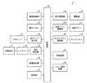
図1に示すように、本体筐体2の上面には、自走式掃除機1に対して指示入力を行う操作パネル50、LED(Light Emitting Diode:発光ダイオード)ランプ51、集塵部30を出し入れする際に開閉する蓋部3が設けられている。なお、本実施形態では本体筐体2は、その上面及び底面が円形を成す形状とするが、この形状に限定されることはない。  As shown in FIG. 1, anoperation panel 50 for inputting instructions to the self-propelledcleaner 1, an LED (Light Emitting Diode)lamp 51, and adust collecting unit 30 are provided on the upper surface of themain body housing 2. Alid 3 is provided that opens and closes when taking in and out. In the present embodiment, themain body housing 2 has a shape in which the upper surface and the bottom surface form a circle, but is not limited to this shape.

LEDランプ51は、本実施形態では、本体筐体2の上面の周囲に設けられており、後述するように、自走式掃除機1の状態に合わせて、点灯する色および点灯パターンが変化するようになっている。なお、LED以外のランプが設けられていてもよい。また、LEDランプは、本体の上面に設けられた排気口7の付近に設けてもよい。  In the present embodiment, theLED lamp 51 is provided around the upper surface of themain body housing 2, and the lighting color and lighting pattern change according to the state of the self-propelledcleaner 1 as described later. It is like that. A lamp other than the LED may be provided. Moreover, you may provide an LED lamp in the vicinity of the exhaust port 7 provided in the upper surface of the main body.

操作パネル50には、ユーザからの操作によって各種の指示、文字、数字などのデータの入力を受け付ける操作スイッチ(操作部)と、ユーザに提示する各種情報を表示するディスプレイ(表示部)と、が設けられている。操作パネル50は、タッチパネルとして設けられていてもよい。また、操作パネル50に、表示用LEDが設けられていてもよい。  Theoperation panel 50 includes an operation switch (operation unit) that receives input of various instructions, data such as characters and numbers, and a display (display unit) that displays various information to be presented to the user. Is provided. Theoperation panel 50 may be provided as a touch panel. Theoperation panel 50 may be provided with a display LED.

図4に操作パネル50の一例を示す。図4に示す操作パネル50は、掃除の開始および停止を指示する「スタート及びストップボタン」501、掃除のモードを選択できる「モード選択ボタン」502、現在時刻や自走式掃除機1を稼動させる予約時刻を設定可能に設けられた「タイマーセットボタン」505、現在時刻や予約時刻を表示する時刻表示部504、後述する集塵容器31が満杯になったことを検知すると点灯するごみ捨てランプ506、を備える。また、操作パネル50は、バッテリー14の充電量を示す「バッテリーマーク」503、を表示する。これらは、単なる例示であり、操作パネル50は、これら以外の機能を実現する操作部や表示部を備えていてもよい。  FIG. 4 shows an example of theoperation panel 50. Theoperation panel 50 shown in FIG. 4 operates a “start and stop button” 501 for instructing start and stop of cleaning, a “mode selection button” 502 for selecting a cleaning mode, and operating the current time and the self-propelledcleaner 1. A “timer set button” 505 provided to set the reservation time, atime display unit 504 for displaying the current time and the reservation time, agarbage disposal lamp 506 that is turned on when it is detected that thedust collecting container 31 described later is full, Is provided. Further, theoperation panel 50 displays a “battery mark” 503 indicating the amount of charge of thebattery 14. These are merely examples, and theoperation panel 50 may include an operation unit and a display unit that realize functions other than these.

図2、3に示すように、本体筐体2の底面には、底面から突出して水平な回転軸29aで回転する一対の駆動輪29が配されている。駆動輪29の回転軸29aは本体筐体2の中心線(中心軸)C上に配置されている。駆動輪29の両輪が同一方向に回転すると自走式掃除機1が進退し、逆方向に回転すると自走式掃除機1が本体筐体2の中心線Cの回りに回転する。駆動輪29がバッテリー14により駆動されることで、自走式掃除機1は自走する。以下で、自走式掃除機1が自走して掃除を行う際の進行方向における前を前方、後ろを後方と呼ぶ。また、掃除を行う際の進行方向に沿った動きを前進、掃除を行う際の進行方向と逆方向に沿った動きを後退と呼ぶ。また。本体筐体2の周面(側面)において、掃除を行う際の進行方向に向かう面を前面、前面と反対側に位置する面を背面と呼ぶ。背面は、後退する際の進行方向に向かう面となる。  As shown in FIGS. 2 and 3, a pair ofdrive wheels 29 that protrude from the bottom surface and rotate about ahorizontal rotation shaft 29 a are arranged on the bottom surface of themain body housing 2. Therotation shaft 29 a of thedrive wheel 29 is disposed on the center line (center axis) C of themain body housing 2. When both wheels of thedrive wheel 29 rotate in the same direction, the self-propelledcleaner 1 advances and retreats, and when rotated in the reverse direction, the self-propelledcleaner 1 rotates around the center line C of themain body housing 2. When thedrive wheel 29 is driven by thebattery 14, the self-propelledcleaner 1 is self-propelled. Below, the front in the advancing direction when the self-propelledcleaner 1 performs self-propelled cleaning is referred to as the front and the rear as the rear. Moreover, the movement along the traveling direction when performing cleaning is called forward, and the movement along the direction opposite to the traveling direction when performing cleaning is called backward. Also. In the peripheral surface (side surface) of themain body housing 2, a surface facing the traveling direction when cleaning is referred to as a front surface, and a surface located on the opposite side of the front surface is referred to as a back surface. The back surface is a surface that faces the traveling direction when the vehicle moves backward.

掃除中、本体筐体2が掃除領域の周縁に到達した場合や進路上の障害物に衝突すると、駆動輪29が停止される。そして、駆動輪29の両輪を互いに逆方向に回転し、本体筐体2の中心線Cを中心に自走式掃除機1本体を回転して向きを変え、旋回する。これにより、所望の掃除領域全体に自走式掃除機1を自走させるとともに障害物を避けて自走させることができる。尚、駆動輪29の両輪を前進時に対して反転して自走式掃除機1を後退させてもよい。  During cleaning, when themain housing 2 reaches the periphery of the cleaning area or when it collides with an obstacle on the path, thedrive wheels 29 are stopped. Then, both wheels of thedrive wheel 29 are rotated in opposite directions, and the main body of the self-propelledcleaner 1 is rotated around the center line C of themain body housing 2 to change its direction and turn. Accordingly, the self-propelledcleaner 1 can be self-propelled over the entire desired cleaning area and can be self-propelled while avoiding obstacles. Note that the self-propelledcleaner 1 may be moved backward by reversing both wheels of thedrive wheel 29 with respect to forward movement.

本体筐体2の底面の前方には、吸込口6が設けられている。吸込口6は本体筐体2の底面に凹設した凹部8の開放面によって床面Fに面して形成されている。凹部8内には水平な回転軸で回転する回転ブラシ9が配され、凹部8の両側方には垂直な回転軸で回転するサイドブラシ10が配されている。  Asuction port 6 is provided in front of the bottom surface of themain body housing 2. Thesuction port 6 is formed so as to face the floor surface F by an open surface of arecess 8 that is recessed in the bottom surface of themain body housing 2. Arotating brush 9 that rotates on a horizontal rotating shaft is disposed in therecess 8, and aside brush 10 that rotates on a vertical rotating shaft is disposed on both sides of therecess 8.

さらに、本体筐体2の底面には、吸込口6のさらに前方にローラー形状の前輪27が設けられている。また、本体筐体2の底面の後方端部(後端)に、自在車輪から成る後輪26が設けられている。自走式掃除機1は、本体筐体2の中心に配した駆動輪29に対して前後方向に重量が配分され、前輪27が床面Fから離れて回転ブラシ9、駆動輪29及び後輪26が床面Fに接地して掃除が行われる。このため、進路前方の塵埃を前輪27により遮ることなく吸込口6に導くことができる。前輪27は進路上に現れた段差に接地し、自走式掃除機1が段差を容易に乗り越えられるようになっている。  Further, a roller-shapedfront wheel 27 is provided on the bottom surface of themain body housing 2 in front of thesuction port 6. Further, arear wheel 26 made of a free wheel is provided at the rear end (rear end) of the bottom surface of themain body housing 2. In the self-propelledcleaner 1, the weight is distributed in the front-rear direction with respect to thedrive wheel 29 disposed in the center of themain body housing 2, and thefront wheel 27 is separated from the floor surface F so that therotary brush 9, thedrive wheel 29, and the rear wheel are separated. 26 is grounded on the floor F and cleaning is performed. For this reason, dust in front of the course can be guided to thesuction port 6 without being blocked by thefront wheel 27. Thefront wheel 27 contacts the step appearing on the course so that the self-propelledcleaner 1 can easily get over the step.

本体筐体2の周囲にはバンパー5が設けられており、自走式掃除機1本体への衝撃や振動を緩衝させる。自走式掃除機1は、走行中に障害物にバンパー5が接触したことを検知すると、進行方向を変更して走行を継続する。  Abumper 5 is provided around themain body housing 2 to buffer the impact and vibration on the main body of the self-propelledcleaner 1. When the self-propelledcleaner 1 detects that thebumper 5 has come into contact with an obstacle during traveling, the traveling direction is changed and the traveling is continued.

本体筐体2の周面(側面)の後端には、バッテリー14の充電を行う充電端子4が露出して設けられている。本実施形態では、充電端子4は本体筐体2の周面の後端の上下に2つ設けられているが、1つあるいは3つ以上設けられていてもよい。自走式掃除機1は、掃除後あるいはバッテリー14の充電量が所定値を下回ると、充電台40の設置されている場所に帰還する。なお、本実施形態では、自走式掃除機1と充電台40とを含む構成を自走式掃除システム(自走式電子機器)100と称する。  A chargingterminal 4 for charging thebattery 14 is exposed at the rear end of the peripheral surface (side surface) of themain body housing 2. In the present embodiment, twocharging terminals 4 are provided above and below the rear end of the peripheral surface of themain body housing 2, but one or three ormore charging terminals 4 may be provided. The self-propelledcleaner 1 returns to the place where the chargingstand 40 is installed after cleaning or when the charge amount of thebattery 14 falls below a predetermined value. In the present embodiment, a configuration including the self-propelledcleaner 1 and the chargingstand 40 is referred to as a self-propelled cleaning system (self-propelled electronic device) 100.

そして、充電台40に設けられた給電端子41に充電端子4を接してバッテリー14を充電する。商用電源に接続される充電台40の背面(本体筐体2の周面と対向しない面)は通常、室内の側壁Sに沿って設置される。充電台40については、後述する。  Then, thebattery 14 is charged by bringing the chargingterminal 4 into contact with thepower supply terminal 41 provided on the chargingstand 40. The rear surface of the chargingbase 40 connected to the commercial power supply (the surface not facing the peripheral surface of the main body housing 2) is usually installed along the side wall S in the room. The chargingstand 40 will be described later.

バッテリー14は、自走式掃除機1全体の電力供給源である。バッテリー14としては、繰り返し充放電が可能な大容量の充電池が望ましい。例えば鉛電池、ニッケル水素電池、リチウムイオン電池あるいはキャパシタ等を使用すればよい。  Thebattery 14 is a power supply source for the entire self-propelledcleaner 1. Thebattery 14 is desirably a large capacity rechargeable battery that can be repeatedly charged and discharged. For example, a lead battery, a nickel metal hydride battery, a lithium ion battery, or a capacitor may be used.

本体筐体2内には塵埃を集塵する集塵部30が配されている。集塵部30は駆動輪29の回転軸29a上方に配され、本体筐体2に設けた集塵室39内に収納されている。集塵部30が駆動輪29の回転軸29aの上方に配されるため、集塵によって重量が大きくなっても本体筐体2の重量バランスが維持される。集塵室39は四方の周面及び底面が覆われた隔離室から成り、本体筐体2内を仕切るように回転ブラシ9の軸方向に延びて形成されている。集塵室39の各壁面は回転ブラシ9の軸方向に延びた前壁を除いてそれぞれ閉塞されている。集塵室39の前壁には凹部8に連通する第1吸気路11及び凹部8の上方に配してモータユニット20に連通する第2吸気路12が設けられている。  Adust collection unit 30 that collects dust is disposed in themain body housing 2. Thedust collection unit 30 is disposed above therotation shaft 29 a of thedrive wheel 29 and is housed in adust collection chamber 39 provided in themain body housing 2. Since thedust collecting unit 30 is disposed above therotating shaft 29a of thedrive wheel 29, the weight balance of themain body housing 2 is maintained even if the weight increases due to dust collection. Thedust collection chamber 39 is composed of an isolation chamber whose four peripheral surfaces and bottom are covered, and is formed to extend in the axial direction of therotary brush 9 so as to partition the inside of themain body housing 2. Each wall surface of thedust collection chamber 39 is closed except for the front wall extending in the axial direction of therotating brush 9. The front wall of thedust collection chamber 39 is provided with afirst intake passage 11 communicating with therecess 8 and asecond intake passage 12 disposed above therecess 8 and communicating with themotor unit 20.

集塵部30は、図5に示すように本体筐体2の蓋部3を開くことで、本体筐体2に対して出し入れが可能になる。集塵部30は、有底の集塵容器31の上部にフィルタ33を有する上部カバー32が取り付けられて形成されている。上部カバー32は可動の係止部32aにより集塵容器31に係止され、係止部32aの操作によって集塵容器31の上面を開閉する。これにより、集塵容器31に堆積した塵埃を廃棄することができる。  As shown in FIG. 5, thedust collecting unit 30 can be inserted into and removed from themain body housing 2 by opening thelid 3 of themain body housing 2. Thedust collection unit 30 is formed by attaching anupper cover 32 having afilter 33 to the upper part of a bottomeddust collection container 31. Theupper cover 32 is locked to thedust collecting container 31 by a movable locking part 32a, and opens and closes the upper surface of thedust collecting container 31 by operating the locking part 32a. Thereby, the dust accumulated in thedust collecting container 31 can be discarded.

集塵容器31の周面には先端に流入口34aを開口して第1吸気路11に連通する流入路34が設けられている。また、集塵容器31内には流入路34に連続して屈曲により下方に気流を導く流入部34bが設けられている。上部カバー32の周面には先端に流出口35aを開口して第2吸気路12に連通する流出路35が設けられている。  On the peripheral surface of thedust collecting container 31, aninflow path 34 that opens to the front end of theinlet 34 a and communicates with thefirst intake path 11 is provided. Further, aninflow portion 34 b that guides the airflow downward by bending is provided in thedust collecting container 31 continuously to theinflow passage 34. On the peripheral surface of theupper cover 32, anoutflow path 35 that opens to the front end and opens to thesecond intake path 12 is provided.

流入口34a及び流出口35aの周囲には集塵室39の前壁に密接するパッキン(図示せず)が設けられる。これにより、集塵部30を収納した集塵室39内が密閉される。流入口34aの開口面、流出口35aの開口面及び集塵室39の前壁は傾斜面に形成され、集塵部30の出し入れ時の摺動によるパッキンの劣化を防止することができる。  A packing (not shown) that is in close contact with the front wall of thedust collecting chamber 39 is provided around theinflow port 34a and theoutflow port 35a. Thereby, the inside of thedust collection chamber 39 in which thedust collection unit 30 is accommodated is sealed. The opening surface of theinflow port 34a, the opening surface of theoutflow port 35a, and the front wall of thedust collecting chamber 39 are formed in an inclined surface, and deterioration of the packing due to sliding when thedust collecting unit 30 is put in and out can be prevented.

本体筐体2内の集塵室39の後方の上部には制御基板15が配される。制御基板15には自走式掃除機1の各部を制御する後述の制御部52や各種データを記憶する後述の記憶部57が設けられる。集塵室39の後方の下部には着脱可能のバッテリー14が配される。バッテリー14は充電端子4を介して充電台40から充電され、制御基板15、駆動輪29、回転ブラシ9、サイドブラシ10及び電動送風機22等の各部に電力を供給する。  Acontrol board 15 is disposed in the upper part of themain body housing 2 behind thedust collection chamber 39. Thecontrol board 15 is provided with a later-describedcontrol unit 52 that controls each part of the self-propelledcleaner 1 and a later-describedstorage unit 57 that stores various data. Adetachable battery 14 is disposed in the lower part of the rear of thedust collection chamber 39. Thebattery 14 is charged from the chargingstand 40 via the chargingterminal 4 and supplies power to thecontrol board 15, thedrive wheel 29, the rotatingbrush 9, theside brush 10, theelectric blower 22, and the like.

上記構成の自走式掃除機1において、掃除運転が指示されると、バッテリー14からの電力が供給されて、電動送風機22、後述のイオン発生装置62、駆動輪29、回転ブラシ9及びサイドブラシ10が駆動される。これにより、自走式掃除機1は、回転ブラシ9、駆動輪29及び後輪26が床面Fに接地して所定の掃除領域を自走し、吸込口6から床面Fの塵埃を含む気流が吸い込まれる。この時、回転ブラシ9の回転によって床面F上の塵埃が掻き上げられて凹部8内に導かれる。また、サイドブラシ10の回転によって吸込口6の側方の塵埃が吸込口6に導かれる。  In the self-propelledcleaner 1 having the above-described configuration, when a cleaning operation is instructed, electric power is supplied from thebattery 14, and theelectric blower 22, anion generator 62, adriving wheel 29, arotating brush 9, and a side brush described later are supplied. 10 is driven. As a result, the self-propelledcleaner 1 causes therotating brush 9, thedrive wheel 29 and therear wheel 26 to come into contact with the floor surface F to self-travel in a predetermined cleaning area, and includes dust on the floor surface F from thesuction port 6. Airflow is inhaled. At this time, the dust on the floor surface F is scraped up by the rotation of therotating brush 9 and guided into therecess 8. Further, the dust on the side of thesuction port 6 is guided to thesuction port 6 by the rotation of theside brush 10.

吸込口6から吸い込まれた気流は図2の矢印A1に示すように第1吸気路11を後方に流通し、流入口34aを介して集塵部30に流入する。集塵部30に流入した気流はフィルタ33により塵埃を捕集され、流出口35aを介して集塵部30から流出する。これにより、集塵容器31内に塵埃が集塵して堆積する。集塵部30から流出した気流は矢印A2に示すように第2吸気路12を前方に流通し、モータユニット20の電動送風機22に流入する。  The airflow sucked from thesuction port 6 flows rearward through thefirst intake passage 11 as shown by an arrow A1 in FIG. 2, and flows into thedust collecting unit 30 through theinflow port 34a. The airflow that has flowed into thedust collector 30 collects dust by thefilter 33 and flows out of thedust collector 30 through theoutlet 35a. Thereby, dust is collected and accumulated in thedust collecting container 31. The airflow flowing out from thedust collection unit 30 flows forward through thesecond intake passage 12 as indicated by an arrow A2 and flows into theelectric blower 22 of themotor unit 20.

電動送風機22を通過した気流は、本体筐体2の上面に設けた排気口7から矢印A3に示すように上方後方に排気される。なお、電動送風機22の近傍にイオン発生装置(図示せず)が備えられており、排気口7からは、イオンを含む気流が排気される。  The airflow that has passed through theelectric blower 22 is exhausted upward and rearward as indicated by an arrow A3 from an exhaust port 7 provided on the upper surface of themain body housing 2. Note that an ion generator (not shown) is provided in the vicinity of theelectric blower 22, and an airflow containing ions is exhausted from the exhaust port 7.

以上のように、室内の掃除が行われるとともに、自走する自走式掃除機1の排気に含まれるイオンが室内に行き渡って室内の除菌や脱臭が行われる。この時、排気口7から上方に向けて排気するので、床面Fの塵埃の巻き上げを防止して室内の清浄度を向上することができる。  As described above, the room is cleaned, and ions contained in the exhaust of the self-propelled self-propelledcleaner 1 are spread throughout the room to be sterilized and deodorized in the room. At this time, since the air is exhausted upward from the exhaust port 7, it is possible to prevent the dust on the floor surface F from being rolled up and improve the cleanliness of the room.

第2吸気路12を通って流れるイオンを含む気流の一部は凹部8に導かれるように構成されていてもよい。このように構成されていると、吸込口6から第1吸気路11に導かれる気流内にイオンが含まれる。これにより、集塵部30の集塵容器31やフィルタ33の除菌及び脱臭を行うことができる。  A part of the airflow containing ions flowing through thesecond intake passage 12 may be guided to therecess 8. If comprised in this way, ion will be contained in the airflow guide | induced to the1st intake path 11 from thesuction inlet 6. FIG. Thereby, sterilization and deodorization of thedust collection container 31 and thefilter 33 of thedust collection part 30 can be performed.

充電台40は、自走式掃除機1のバッテリー14を充電させるための装置であり、充電台40は内部には、バッテリー14への充電を制御する充電回路等を備えている。  The chargingstand 40 is a device for charging thebattery 14 of the self-propelledcleaner 1, and the chargingstand 40 includes a charging circuit for controlling charging of thebattery 14 and the like inside.

図6に示すように、充電台40の前面(本体筐体2の周面と対向する面)には、自走式掃除機1の充電端子4と接触可能な位置に、自走式掃除機1の充電端子4と同数の、給電端子41が設けられている。給電端子41は、何とも接触していない状態では、充電台40の前面から突出しており、給電端子41の先端面と充電台40の前面とがほぼ平らになるまで押し戻すことが可能になっている。自走式掃除機1の充電端子4が充電台40の給電端子41と接触(電気的接続)したまま、給電端子41の先端面が充電台40の前面とほぼ平らになるまでに押されると、接点と導通して、充電台40が接続した商用電源からの電流が、自走式掃除機1に流れる。この状態にてバッテリー14を充電させることができる。  As shown in FIG. 6, the front surface of the charging stand 40 (the surface facing the peripheral surface of the main body housing 2) has a self-propelled cleaner at a position where it can come into contact with the chargingterminal 4 of the self-propelledcleaner 1. The same number offeeding terminals 41 as thecharging terminals 4 are provided. Thepower supply terminal 41 protrudes from the front surface of the chargingstand 40 in a state where it is not in contact with anything, and can be pushed back until the front end surface of thepower supply terminal 41 and the front surface of the chargingstand 40 become substantially flat. . When the chargingterminal 4 of the self-propelledcleaner 1 is in contact (electrically connected) with thepower supply terminal 41 of the chargingbase 40 and is pushed until the front end surface of thepower supply terminal 41 becomes substantially flat with the front surface of the chargingbase 40. The electric current from the commercial power source connected to the chargingstand 40 flows through the self-propelledcleaner 1 in conduction with the contact. In this state, thebattery 14 can be charged.

また、充電台40は、充電台40の設置場所及び給電端子41の位置を示す帰還信号を発信するように構成されている。自走式掃除機1は、掃除終了を検知した場合あるいはバッテリー14の充電量が所定値を下回った場合には、充電台40から発せられた帰還信号を検知して充電台40の設置されている場所に自動的に帰還する。ここで、掃除終了の検知は、例えば、自走式掃除機1が、一定距離移動あるいは一定時間経過したことを検知、あるいは、センサ等で掃除領域の清掃状態を検知することにより行われてもよい。または、自走式掃除機1が、操作パネル50あるいは後述するリモコン装置や無線通信により接続した端末装置から、掃除終了指示や中断指示等の充電台40への帰還を促す指示を受け付けることで、行われてもよい。  Further, the chargingstand 40 is configured to transmit a feedback signal indicating the installation location of the chargingstand 40 and the position of thepower supply terminal 41. When the self-propelledcleaner 1 detects the end of cleaning or the charge amount of thebattery 14 falls below a predetermined value, the self-propelledcleaner 1 detects the feedback signal emitted from the chargingbase 40 and the chargingbase 40 is installed. Return home automatically. Here, the end of cleaning may be detected, for example, by detecting that the self-propelledcleaner 1 has moved a certain distance or a certain time has passed, or by detecting the cleaning state of the cleaning area with a sensor or the like. Good. Alternatively, the self-propelledcleaner 1 receives an instruction prompting the user to return to the chargingstand 40 such as a cleaning end instruction or an interruption instruction from theoperation panel 50 or a remote control device described later or a terminal device connected by wireless communication. It may be done.

本実施形態では、充電台40の設置場所及び給電端子41の位置を示す帰還信号として赤外線信号が発信されるものとするが、赤外線信号以外の信号が発信されてもよい。帰還信号は、充電台40が商用電源に接続されており、自走式掃除機1が充電台40から離れていれば、常時発信される。  In the present embodiment, an infrared signal is transmitted as a feedback signal indicating the installation location of the chargingstand 40 and the position of thepower supply terminal 41, but a signal other than the infrared signal may be transmitted. The feedback signal is always transmitted if the chargingstand 40 is connected to a commercial power source and the self-propelledcleaner 1 is away from the chargingstand 40.

本実施形態では、自走式掃除機1は、帰還信号を検知して、前進(言い換えれば、前面を進行方向に向けて進行)して充電台40の設置場所付近まで戻ってくると、一時停止し、充電端子4が給電端子41と対向する位置に来るまで、本体筐体2の中心線C周りに旋回する。その後、本体筐体2は後退(言い換えれば、背面を進行方向に向けて進行)を開始する。自走式掃除機1は、充電端子4が給電端子41に接触した後、さらに後退して、充電端子4と接触している給電端子41の先端面と充電台40の前面とがほぼ平らになる位置(給電端子41の押し戻しが止まる位置、ドッキング位置)まで来ると、給電端子41からの通電を検知し、後退を停止する。この停止した状態で、充電が行われる。なお、自走式掃除機1の帰還および充電端子4と給電端子41とのドッキング(自走式掃除機1と充電台40とのドッキング)に関する処理は、公知の技術を用いることができる。  In the present embodiment, the self-propelledcleaner 1 detects a return signal, moves forward (in other words, moves forward in the direction of travel), and returns to the vicinity of the place where the chargingstand 40 is installed. It stops and turns around the center line C of themain body housing 2 until the chargingterminal 4 comes to a position facing thepower supply terminal 41. Thereafter, themain body housing 2 starts retreating (in other words, the rear surface proceeds in the traveling direction). In the self-propelledcleaner 1, after the chargingterminal 4 comes into contact with thepower supply terminal 41, the self-propelledcleaner 1 is further retracted so that the front end surface of thepower supply terminal 41 in contact with the chargingterminal 4 and the front surface of the chargingstand 40 are substantially flat. When it reaches a position (position where the pushing back of thepower supply terminal 41 stops, docking position), the power supply from thepower supply terminal 41 is detected and the backward movement is stopped. Charging is performed in this stopped state. In addition, the process regarding the return of the self-propelledcleaner 1 and the docking of the chargingterminal 4 and the power supply terminal 41 (the docking of the self-propelledcleaner 1 and the charging stand 40) can use a known technique.

充電端子4と給電端子41とのドッキングは、例えば、本体筐体2の背面(後端)に後方センサを設置し、後方センサで帰還信号を検知しながら、自走式掃除機1を後退させることで行うことができる。後方センサが、帰還信号を検知しなくなると、自走式掃除機1を本体筐体2の中心線C周りに微量に正転(時計回り)または逆転(反時計回り)させ、帰還信号を検知してから、後退を行う。このように、常に帰還信号の検知を維持しながら本体筐体2を後退させることで、充電端子4と給電端子41との位置を合わせることができる。  For docking between the chargingterminal 4 and thepower supply terminal 41, for example, a rear sensor is installed on the back surface (rear end) of themain body housing 2, and the self-propelledcleaner 1 is moved backward while detecting a return signal with the rear sensor. Can be done. When the rear sensor no longer detects the feedback signal, the self-propelledcleaner 1 is rotated forward (clockwise) or reversely (counterclockwise) by a small amount around the center line C of themain body housing 2 to detect the feedback signal. And then move backwards. In this way, the positions of the chargingterminal 4 and thepower feeding terminal 41 can be aligned by retracting themain body housing 2 while always detecting the feedback signal.

なお、後方センサ及び充電端子4は共に駆動輪29の回転軸29aと平行な線上に設けられるのが好ましい。このように設けられていると、後方センサが充電台40からの帰還信号の検知を維持しながら後退して、充電端子4を給電端子41に接続させることが適切に行える。  Both the rear sensor and the chargingterminal 4 are preferably provided on a line parallel to therotation shaft 29 a of thedrive wheel 29. If provided in this way, the rear sensor moves backward while maintaining detection of the feedback signal from the chargingstand 40, and the chargingterminal 4 can be appropriately connected to thepower feeding terminal 41.

また、自走式掃除機1は、設定によって、充電端子4と給電端子41とが接続している状態、つまり、バッテリー14の充電中および充電終了後に、電動送風機22及びイオン発生装置を駆動できるように構成されていてもよい。このように構成されていると、充電中および充電終了後に、排気口7から上方後方にイオンを含む気流が送出される。充電端子4が本体筐体2の後端に設けられているため、イオンを含む気流は充電台40の方向に流通する。ここで、充電台40の背面が室内の側壁Sに沿って設置される場合、イオンを含む気流は、側壁Sに沿って上昇する。該気流は室内の天井壁及び対向する側壁に沿って流通する。従って、イオンが室内全体に行き渡り、除菌効果や脱臭効果を向上させることができる。  Moreover, the self-propelledcleaner 1 can drive theelectric blower 22 and the ion generating device in a state where the chargingterminal 4 and thepower feeding terminal 41 are connected by setting, that is, while thebattery 14 is being charged and after the charging is completed. It may be configured as follows. If comprised in this way, the airflow containing ion will be sent out upwards and backwards from the exhaust port 7 during charge and after completion | finish of charge. Since the chargingterminal 4 is provided at the rear end of themain body housing 2, the airflow including ions flows in the direction of the chargingstand 40. Here, when the back surface of the chargingstand 40 is installed along the indoor side wall S, the airflow including ions rises along the side wall S. The airflow circulates along the indoor ceiling wall and the opposite side wall. Accordingly, the ions are spread throughout the room, and the sterilizing effect and the deodorizing effect can be improved.

また、自走式掃除機1に、周辺環境の状態を検知する環境検知部が設けられており、環境検知部が検知した周辺環境の状態に基づいて、特定箇所に一定時間留まり、排気口7からイオンを含む気流を送出するように構成されていてもよい。  In addition, the self-propelledcleaner 1 is provided with an environment detection unit that detects the state of the surrounding environment. Based on the state of the surrounding environment detected by the environment detection unit, the self-propelledcleaner 1 stays at a specific location for a certain period of time, May be configured to deliver an air stream containing ions.

本実施形態では、自走式掃除機1は、自機に備えられた操作パネル50だけでなく、IrDA、IrSS(登録商標)などの赤外線通信によってリモコン装置(図示せず)からも操作が行えるようになっている。また、自走式掃除機1は、Bluetooth(登録商標)、WiFi(登録商標)、ZigBee(登録商標)などの無線通信により接続したスマートフォン等の端末装置(図示せず)を介して操作を行うこともできるようになっている。また、自走式掃除機1から、無線通信により接続した端末装置にデータを送信することも可能となっている。つまり、自走式掃除機1は、無線電波方式で接続した端末装置とは双方向通信が可能である。また、自走式掃除機1は、広域の無線ネットワークに接続してもよい。この場合には、広域の無線ネットワークに接続した端末装置から自走式掃除機1に対する操作が行うことができる。  In the present embodiment, the self-propelledcleaner 1 can be operated not only from theoperation panel 50 provided in the self-machine, but also from a remote control device (not shown) by infrared communication such as IrDA and IrSS (registered trademark). It is like that. The self-propelledcleaner 1 is operated via a terminal device (not shown) such as a smartphone connected by wireless communication such as Bluetooth (registered trademark), WiFi (registered trademark), ZigBee (registered trademark), or the like. You can also do that. Moreover, it is also possible to transmit data from the self-propelledcleaner 1 to a terminal device connected by wireless communication. That is, the self-propelledcleaner 1 can perform two-way communication with a terminal device connected by a wireless radio wave method. Self-propelledcleaner 1 may be connected to a wide area wireless network. In this case, the operation of the self-propelledcleaner 1 can be performed from a terminal device connected to a wide area wireless network.

さらに、自走式掃除機1は、音声による入力操作が可能になっていてもよい。また、自走式掃除機1は、自走式掃除機1に記憶している音声データを出力するように構成されていてもよい。  Furthermore, the self-propelledcleaner 1 may be capable of performing voice input operations. Moreover, the self-propelledcleaner 1 may be configured to output sound data stored in the self-propelledcleaner 1.

また、自走式掃除機1は各種センサを備えており、障害物を回避して段差や階段から落ちることなく自走することができるように構成されている。このようなセンサとして、例えば、クリフセンサ(段差検知センサ)、障害物検知センサ、人感センサ、CCD(Charge-Coupled Device)カメラなどが挙げられる。これらは単なる例示であり、またこれら全てを備えている必要はない。クリフセンサや人感センサは、例えば赤外線センサ、また、障害物検知センサは、例えば超音波センサにて構成することができる。  Moreover, the self-propelledcleaner 1 includes various sensors, and is configured to avoid obstacles and to be able to self-propel without falling from steps or stairs. Examples of such sensors include a cliff sensor (step detection sensor), an obstacle detection sensor, a human sensor, a CCD (Charge-Coupled Device) camera, and the like. These are merely examples and need not all be provided. The cliff sensor and the human sensor can be configured by, for example, an infrared sensor, and the obstacle detection sensor can be configured by, for example, an ultrasonic sensor.

また、自走式掃除機1は、例えば、加速度センサ、距離検知センサ、角度センサなどを備えており、掃除中の動作が制御されてもよい。さらに、自走式掃除機1は、温度センサ、湿度センサ、臭気センサ等を備え、センシング結果に応じた掃除をするように制御されてもよい。  Self-propelledcleaner 1 is provided with an acceleration sensor, a distance detection sensor, an angle sensor, etc., for example, and operation during cleaning may be controlled. Furthermore, the self-propelledcleaner 1 may include a temperature sensor, a humidity sensor, an odor sensor, and the like, and may be controlled to perform cleaning according to the sensing result.

本実施形態では、自走式掃除機1を、吸引式の掃除機として説明しているが、自走式掃除機1は、例えば、モップ式の掃除機にも適用することができる。また、自走式掃除機1は、家庭用だけでなく、業務用のものであってもよい。また、本実施形態では、自走式掃除機1はイオン発生装置62を備えているが、必ずしも備えていなくてもよい。  In the present embodiment, the self-propelledcleaner 1 is described as a suction-type cleaner, but the self-propelledcleaner 1 can also be applied to, for example, a mop-type cleaner. Self-propelledcleaner 1 may be not only for home use but also for business use. Moreover, in this embodiment, although the self-propelledcleaner 1 is provided with theion generator 62, it does not necessarily need to be provided.

(自走式掃除機の機能的構成)
次に、自走式掃除機1の機能的構成について説明する。自走式掃除機1は、図7に示すように、制御部52、通信制御部53、操作パネル50、LEDランプ点灯部54、LEDランプ51、電圧検出部55、充電端子4、バッテリー14、通電検知部56、記憶部57、走行駆動部58、回転ブラシ駆動部59、回転ブラシ9、サイドブラシ駆動部60、サイドブラシ10、駆動輪29、送風装置61、イオン発生装置62を、備えている。前出した部材については説明を省略する。
(Functional configuration of self-propelled vacuum cleaner)
Next, the functional configuration of the self-propelledcleaner 1 will be described. As shown in FIG. 7, the self-propelledcleaner 1 includes acontrol unit 52, acommunication control unit 53, anoperation panel 50, an LEDlamp lighting unit 54, anLED lamp 51, avoltage detection unit 55, a chargingterminal 4, abattery 14, Anenergization detection unit 56, astorage unit 57, atravel drive unit 58, a rotarybrush drive unit 59, arotary brush 9, a sidebrush drive unit 60, aside brush 10, adrive wheel 29, ablower 61, and anion generator 62 are provided. Yes. Description of the previously described members is omitted.

制御部52は、記憶部57に記憶されたプログラムやデータ、さらに、前出の操作パネル50、リモコン装置、無線通信により接続した端末装置から入力されたプログラム、データに基づき、自走式掃除機1の各種動作の制御を行うブロックである。制御部52は、前記した制御基板15に設けられる。  Thecontrol unit 52 is a self-propelled cleaner based on the programs and data stored in thestorage unit 57 and the programs and data input from theoperation panel 50, the remote control device, and the terminal device connected by wireless communication. 1 is a block for controlling various operations of 1. Thecontrol unit 52 is provided on thecontrol board 15 described above.

通信制御部53は、外部装置とのデータの送受信を制御するブロックである。前出したリモコン装置あるいは無線通信により接続した端末装置から、自走式掃除機1を制御するための制御信号などを受信する。また、無線通信により接続した端末装置に対して、自走式掃除機1に記憶しているデータや自走式掃除機1にて測定可能なデータを送信する。通信制御部53は、また、充電台40からの帰還信号を受信する。  Thecommunication control unit 53 is a block that controls data transmission / reception with an external device. A control signal or the like for controlling the self-propelledcleaner 1 is received from the remote controller or the terminal device connected by wireless communication. Moreover, the data memorize | stored in the self-propelledcleaner 1 and the data measurable with the self-propelledcleaner 1 are transmitted with respect to the terminal device connected by radio | wireless communication. Thecommunication control unit 53 also receives a feedback signal from the chargingstand 40.

LEDランプ点灯部54は、LEDランプ51に駆動電流を供給し、LEDランプ51の点灯を制御するブロックである。LEDランプ点灯部54は、自走式掃除機1の状態に合わせて、点灯する色および点灯パターンを変化させる。例えば、掃除を行っている掃除モード、充電中である充電モード、掃除を行わずにイオン発生を行っている(イオン発生については後述する)イオン発生モード、緊急事態が発生している緊急事態モード、により色および点灯パターンを変化させてもよい。  The LEDlamp lighting unit 54 is a block that supplies driving current to theLED lamp 51 and controls the lighting of theLED lamp 51. The LEDlamp lighting unit 54 changes the lighting color and lighting pattern in accordance with the state of the self-propelledcleaner 1. For example, cleaning mode for cleaning, charging mode for charging, ion generation without cleaning (ion generation will be described later), emergency mode for emergency , The color and lighting pattern may be changed.

電圧検出部55は、バッテリー14の電圧を検出するブロックであり、検出した電圧からバッテリー14の充電量を求める。バッテリー14には、充電端子4が電気的に接続されるよう構成されている。  Thevoltage detection unit 55 is a block that detects the voltage of thebattery 14, and obtains the charge amount of thebattery 14 from the detected voltage. The chargingterminal 4 is electrically connected to thebattery 14.

通電検知部56は、給電端子41から充電端子4への通電を検知するブロックである。  Theenergization detection unit 56 is a block that detects energization from thepower supply terminal 41 to the chargingterminal 4.

記憶部57は、(1)自走式掃除機1の制御部52が実行する制御プログラム、(2)制御部52が実行するOSプログラム、(3)制御部52が、自走式掃除機1が有する各種機能を実行するためのアプリケーションプログラム、および、(4)該アプリケーションプログラムを実行するときに読み出す各種データを記憶するものである。あるいは、(5)制御部52が各種機能を実行する過程で演算に使用するデータおよび演算結果等を記憶するものである。例えば、上記の(1)〜(4)のデータは、ROM(read only memory)、フラッシュメモリ、EPROM(Erasable Programmable ROM)、EEPROM(Electrically EPROM)、HDD(Hard Disc Drive)などの不揮発性記憶装置に記憶される。例えば、上記の(5)のデータは、RAM(Random Access Memory)などの揮発性記憶装置に記憶される。  Thestorage unit 57 includes (1) a control program executed by thecontrol unit 52 of the self-propelledcleaner 1, (2) an OS program executed by thecontrol unit 52, and (3) thecontrol unit 52 of the self-propelledcleaner 1 And (4) various data to be read when the application program is executed. Alternatively, (5) thecontrol unit 52 stores data and calculation results used for calculations in the course of executing various functions. For example, the above data (1) to (4) are stored in a nonvolatile storage device such as a ROM (read only memory), a flash memory, an EPROM (Erasable Programmable ROM), an EEPROM (Electrically EPROM), an HDD (Hard Disc Drive), etc. Is remembered. For example, the data (5) is stored in a volatile storage device such as a RAM (Random Access Memory).

また、記憶部57は、操作パネル50、あるいは、通信制御部53を介して前出のリモコン装置や端末装置から受け付けた、自走式掃除機1の動作に係る各種条件設定を、記憶する。さらに、記憶部57は、自走式掃除機1の設置場所周辺の走行マップを記憶してもよい。走行マップとは、自走式掃除機1の走行経路や走行速度などといった走行に関する情報、あるいは、掃除する領域に関する情報である。走行マップは、予めユーザが設定して記憶部57に記憶させてもよいし、自走式掃除機1自身が自動的に記録するように構成されていてもよい。  In addition, thestorage unit 57 stores various condition settings relating to the operation of the self-propelledcleaner 1 received from the remote control device or the terminal device described above via theoperation panel 50 or thecommunication control unit 53. Furthermore, thestorage unit 57 may store a travel map around the installation location of the self-propelledcleaner 1. The travel map is information related to travel such as the travel route and travel speed of the self-propelledcleaner 1 or information related to the area to be cleaned. The travel map may be set in advance by the user and stored in thestorage unit 57, or the self-propelledcleaner 1 itself may be automatically recorded.

走行駆動部58は、モータドライバ、駆動輪モータ等を備え、制御部52からの制御信号に基づき、回転方向、回転角度等を決定して、駆動輪29を駆動させるブロックである。  Thetravel drive unit 58 includes a motor driver, a drive wheel motor, and the like, and is a block that drives thedrive wheels 29 by determining a rotation direction, a rotation angle, and the like based on a control signal from thecontrol unit 52.

回転ブラシ駆動部59は、モータドライバ、回転ブラシモータ等を備え、制御部52からの制御信号に基づき、回転数等を決定して、回転ブラシ9を駆動させるブロックである。  The rotatingbrush drive unit 59 includes a motor driver, a rotating brush motor, and the like, and is a block that determines the number of rotations and the like based on a control signal from thecontrol unit 52 and drives therotating brush 9.

サイドブラシ駆動部60は、モータドライバ、サイドブラシモータ等を備え、制御部52からの制御信号に基づき、回転数等を決定して、サイドブラシ10を駆動させるブロックである。  The sidebrush drive unit 60 includes a motor driver, a side brush motor, and the like, and is a block that determines the number of rotations and the like based on a control signal from thecontrol unit 52 and drives theside brush 10.

送風装置61は、前出のモータユニット20に相当し、電動送風機22等を備え、本体筐体2の内部への吸気及び内部からの排気を行う装置である。  Theblower device 61 corresponds to themotor unit 20 described above, and includes theelectric blower 22 and the like, and is a device that performs intake and exhaust from the inside of themain body housing 2.

イオン発生装置62は、制御部52による制御の下、駆動されるとイオンを発生させる装置である。イオン発生装置62の詳細については実施の形態2に記す。イオン発生装置62にて発生したイオンは、送風装置61によって、本体筐体2の外部に排出される。なお、制御部52の制御により、自走式掃除機1は、掃除の動作とイオン発生の動作とを同時に実行できるほか、掃除の動作とイオン発生の動作とを各々単独で実行することも可能である。  Theion generator 62 is an apparatus that generates ions when driven under the control of thecontroller 52. Details of theion generator 62 will be described in the second embodiment. Ions generated by theion generator 62 are discharged to the outside of themain body housing 2 by theblower 61. The self-propelledcleaner 1 can execute the cleaning operation and the ion generation operation at the same time under the control of thecontrol unit 52, and can also execute the cleaning operation and the ion generation operation independently. It is.

(充電端子清掃処理)
自走式掃除システム100では、自走式掃除機1と充電台40とのドッキング時に充電端子4を清掃するための処理(充電端子清掃処理)が実行される。この充電端子清掃処理について、図8を用いて説明する。
(Charging terminal cleaning process)
In the self-propelledcleaning system 100, a process for cleaning the charging terminal 4 (charging terminal cleaning process) is performed when the self-propelledcleaner 1 and the chargingstand 40 are docked. This charging terminal cleaning process will be described with reference to FIG.

ドッキング時、自走式掃除機1の制御部52は、走行駆動部58を制御し、充電端子4を給電端子41に向けて自走式掃除機1を移動させる(S1)。そして、充電端子4が給電端子41と接触しているかを検知する(S2)。本実施形態では、通電検知部56が給電端子41から充電端子4への通電を検知することで、充電端子4と給電端子41との接触を検知する。これ以外の方法で充電端子4と給電端子41との接触が検知されるように構成されていてもよい。  At the time of docking, thecontrol unit 52 of the self-propelledcleaner 1 controls the travelingdrive unit 58 to move the self-propelledcleaner 1 with the chargingterminal 4 facing the power supply terminal 41 (S1). Then, it is detected whether the chargingterminal 4 is in contact with the power supply terminal 41 (S2). In the present embodiment, theenergization detection unit 56 detects the energization from thepower supply terminal 41 to thecharge terminal 4, thereby detecting contact between thecharge terminal 4 and thepower supply terminal 41. You may be comprised so that the contact with the chargingterminal 4 and the electricpower feeding terminal 41 may be detected by methods other than this.

充電端子4と給電端子41とが接触していることが検知されると(S2でYES)、制御部52は、走行駆動部58を制御し、充電端子4を給電端子41に接触させながら、自走式掃除機1を中心線C周りに所定回数および所定角度で、正転逆転させ(S3)、停止する。停止した後は、通常の通電が開始される。充電端子4と給電端子41との接触が検知されない場合(S2にてNO)、S1に戻る。正転逆転は、時計回りの回転および反時計回りの回転と言い換えることもできる。  When it is detected that the chargingterminal 4 and thepower feeding terminal 41 are in contact (YES in S2), thecontrol unit 52 controls thetravel driving unit 58 to bring the chargingterminal 4 into contact with thepower feeding terminal 41, The self-propelledcleaner 1 is rotated forward and backward at a predetermined number of times and at a predetermined angle around the center line C (S3) and stopped. After stopping, normal energization is started. If contact between charging terminal 4 andpower feeding terminal 41 is not detected (NO in S2), the process returns to S1. Forward rotation and reverse rotation can also be referred to as clockwise rotation and counterclockwise rotation.

正転逆転する際の角度は、充電端子4と給電端子41との接触が外れない角度であればよい。正転逆転を繰り返す回数は、例えば、5回程度であればよいが、この数値に限定はされない。  The angle at the time of forward and reverse rotation may be an angle at which the contact between the chargingterminal 4 and thepower feeding terminal 41 is not removed. The number of times of normal rotation and reverse rotation may be, for example, about 5 times, but is not limited to this value.

以上のように、制御部52が、走行駆動部58を制御し、充電端子4を給電端子41に接触させながら自走式掃除機1を正転逆転させることで、充電端子4と給電端子41とが相対的に摺動する。よって、これらの間の摩擦によって、自走式掃除機1の充電端子4に付着した塵や埃などの汚れ(異物)を容易に取り除くことができる。また、充電台の給電端子に付着した塵や埃などの汚れが付着している場合には給電端子41の汚れも容易に取り除くことができる。このように、自走式掃除システム100では、充電端子4または給電端子41に付着した塵や埃などの汚れを自動的に取り除くことができる。そのため、ユーザによる充電端子4および給電端子41の清掃作業を軽減させることができる。また、充電端子4または給電端子41の塵や埃などの汚れを取り除くことで、充電端子4と給電端子41との間の充電時の接触不良を抑制することができ、自走式掃除機1に対して適切な充電が行える。  As described above, thecontrol unit 52 controls the travelingdrive unit 58 to rotate the self-propelledcleaner 1 forward and backward while the chargingterminal 4 is in contact with thepower feeding terminal 41, so that the chargingterminal 4 and thepower feeding terminal 41 are rotated. And slide relative to each other. Therefore, dirt (foreign matter) such as dust and dirt attached to the chargingterminal 4 of the self-propelledcleaner 1 can be easily removed by friction between them. Further, when dirt such as dust or dust attached to the power supply terminal of the charging stand is attached, thepower supply terminal 41 can be easily removed. Thus, in the self-propelledcleaning system 100, dirt such as dust and dirt attached to the chargingterminal 4 or thepower supply terminal 41 can be automatically removed. Therefore, the cleaning work of the chargingterminal 4 and thepower feeding terminal 41 by the user can be reduced. Further, by removing dirt such as dust or dust from the chargingterminal 4 or thepower supply terminal 41, it is possible to suppress poor contact during charging between the chargingterminal 4 and thepower supply terminal 41, and the self-propelledcleaner 1 Can be charged properly.

自走式掃除機1に元々備えられている走行駆動部58を、上記のように制御するだけで、容易に、充電端子4と給電端子41とを相対的に摺動させることができる。よって、摺動させるための新たな構成は不要であり、コストを抑制して、充電端子4または給電端子41に付着した塵や埃などの汚れを取り除くことができる。  The chargingterminal 4 and thepower feeding terminal 41 can be easily slid relative to each other only by controlling the travelingdrive unit 58 originally provided in the self-propelledcleaner 1 as described above. Accordingly, a new configuration for sliding is unnecessary, and costs can be suppressed and dirt such as dust and dirt attached to the chargingterminal 4 or thepower supply terminal 41 can be removed.

また、制御部52は、塵や埃などの異物が充電端子4に付着していることを検知してから、充電端子清掃処理を実行するように制御してもよい。充電端子4の異物を検知する異物検知部として、例えば、自走式掃除機1にCCDカメラを設けてもよい。あるいは、充電台40にCCDカメラを設けて、充電台40のCCDカメラが撮影した情報を、自走式掃除機1が充電台40から受信して、解析することで、充電端子4の異物を検知するように構成されていてもよい。  Further, thecontrol unit 52 may perform control so as to execute the charging terminal cleaning process after detecting that foreign matter such as dust or dust is attached to the chargingterminal 4. For example, a CCD camera may be provided in the self-propelledcleaner 1 as a foreign matter detection unit that detects foreign matter in the chargingterminal 4. Alternatively, the chargingstand 40 is provided with a CCD camera, and the self-propelledcleaner 1 receives the information taken by the CCD camera of the charging stand 40 from the chargingstand 40 and analyzes it. It may be configured to detect.

制御部52は、例えば、所定時間毎に充電端子清掃処理を実行するよう制御してもよい。あるいは、制御部52は、バッテリー14の充電後に自走式掃除機1が掃除を実行した回数をカウントし、カウントした回数が所定数に達すると、充電端子清掃処理を実行するように制御してもよい。所定時間や所定数は、操作パネル50あるいは、前出のリモコン装置や端末装置から、変更できるようになっていてもよい。この場合、充電端子または給電端子の清掃を実行する時間やタイミングをユーザの所望するものに変更することができる。  For example, thecontrol unit 52 may perform control so that the charging terminal cleaning process is executed every predetermined time. Alternatively, thecontrol unit 52 counts the number of times the self-propelledcleaner 1 performs cleaning after thebattery 14 is charged, and controls the charging terminal cleaning process to be executed when the counted number reaches a predetermined number. Also good. The predetermined time and the predetermined number may be changed from theoperation panel 50 or the remote controller or terminal device described above. In this case, the time and timing for executing the cleaning of the charging terminal or the power feeding terminal can be changed to those desired by the user.

上記では、走行駆動部58を制御することで、充電端子4と給電端子41とを相対的に摺動させたが、例えば、次のように構成されていてもよい。例えば、充電端子4と給電端子41とを接触させながら、充電端子4あるいは本体筐体2のみを運動させて、充電端子4と給電端子41とを相対的に摺動させてよい。あるいは、充電端子4と給電端子41とを接触させながら、給電端子41あるいは充電台40を運動させて、充電端子4と給電端子41とを相対的に摺動させてもよい。この場合、充電台40に給電端子41または充電台を振動させる駆動部および駆動を制御する制御部が設けられる。  In the above description, the travelingdrive unit 58 is controlled so that the chargingterminal 4 and thepower feeding terminal 41 are slid relative to each other, but may be configured as follows, for example. For example, the chargingterminal 4 and thepower supply terminal 41 may be slid relative to each other by moving only the chargingterminal 4 or themain body housing 2 while contacting the chargingterminal 4 and thepower supply terminal 41. Alternatively, the chargingterminal 4 and the feedingterminal 41 may be slid relative to each other by moving the feedingterminal 41 or the chargingstand 40 while contacting the chargingterminal 4 and the feedingterminal 41. In this case, the chargingbase 40 is provided with apower feeding terminal 41 or a driving unit that vibrates the charging base and a control unit that controls driving.

上記の本実施形態では、自走式掃除機1と充電台40とを備えた自走式掃除システム100におけるドッキング時の充電端子の清掃処理について説明したが、このような清掃処理は、例えば、二次電池を駆動源とした移動体と当該移動体を充電するための充電台とを備えたシステムにも適応可能である。  In the above-described embodiment, the cleaning process of the charging terminal at the time of docking in the self-propelledcleaning system 100 including the self-propelledcleaner 1 and the chargingstand 40 has been described. The present invention can also be applied to a system including a moving body using a secondary battery as a driving source and a charging base for charging the moving body.

〔実施の形態2〕
本発明の他の実施形態として、本発明の電子機器を自走式空気清浄機に適用した場合について、図を参照して説明すれば、以下の通りである。なお、本実施形態の自走式空気清浄機(電子機器)110は、基本的には、実施の形態1の自走式掃除機1の掃除機能がなく、空気清浄機能を有するものとして構成される。よって、実施の形態1で説明した構成と同様の機能を有する構成については同じ番号を付し説明を省略する。
[Embodiment 2]
As another embodiment of the present invention, a case where the electronic apparatus of the present invention is applied to a self-propelled air cleaner will be described with reference to the drawings. In addition, the self-propelled air cleaner (electronic device) 110 according to the present embodiment is basically configured to have the air cleaning function without the cleaning function of the self-propelledcleaner 1 according to the first embodiment. The Therefore, the same number is attached | subjected about the structure which has the function similar to the structure demonstrated inEmbodiment 1, and description is abbreviate | omitted.

(自走式空気清浄機の構造)
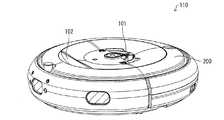
図9,10に、ぞれぞれ、本実施形態の自走式空気清浄機110の斜視図、側面断面図を示す。
(Structure of self-propelled air purifier)
9 and 10 are a perspective view and a side sectional view of the self-propelledair cleaner 110 of the present embodiment, respectively.

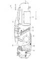
自走式空気清浄機110は、図9に示すように、外枠が平面視円形の本体筐体200で形成された自走式空気清浄機110本体と、図10に示すように、バッテリー(二次電池)14を電力供給源として駆動される駆動輪(図示せず)とを有し、自走しながら空気を清浄化する装置である。自走式空気清浄機110は、モータにより回転ファン104を回転駆動させて気流を発生させ、吸気口101から吸気した空気を内部のフィルタ105を通過させて、イオン発生装置62にて発生させたイオンを混入して排気口102から排気する。図10の白抜きの矢印は回転ファン104を回転させたときの空気の流れを示すものである。  As shown in FIG. 9, the self-propelledair cleaner 110 includes a self-propelledair cleaner 110 main body having an outer frame formed of amain body housing 200 having a circular shape in plan view, and a battery ( Thesecondary battery 14 is a device that has a drive wheel (not shown) driven by using thepower supply source 14 as a power supply source, and purifies the air while traveling on its own. The self-propelledair cleaner 110 rotationally drives therotary fan 104 by a motor to generate an air flow, and the air sucked from theair inlet 101 passes through theinternal filter 105 and is generated by theion generator 62. Ions are mixed and exhausted from theexhaust port 102. The white arrows in FIG. 10 indicate the air flow when therotary fan 104 is rotated.

図9に示すように、本体筐体200の上面には、吸気ポート103が設けられている。吸気ポート103は、本体筐体200の上面の一部を覆うもので、吸気口101に異物やごみや埃等が入らないようにするために、自走式空気清浄機110が停止している状態では、吸気ポート103は吸気口101を塞ぐ位置まで下方に下がっている。図10は、装置が動作中で吸気ポートが上方に移動している状態である。吸気ポート103がこのように上方へ移動している状態にあると空気を吸気可能となる。なお、吸気ポート103を本体筐体200から取り外すと、自走式空気清浄機110は、図11に示す状態となる。ただし、吸気ポート103は通常取り外せないようになっている。また、図示しないが、本体筐体200上面には、自走式空気清浄機110に対して指示入力を行う操作パネルが設けられる。  As shown in FIG. 9, anintake port 103 is provided on the upper surface of themain body casing 200. Theintake port 103 covers a part of the upper surface of themain body casing 200, and the self-propelledair cleaner 110 is stopped so that foreign matter, dust, dust, or the like does not enter theintake port 101. In the state, theintake port 103 is lowered downward to a position where theintake port 101 is blocked. FIG. 10 shows a state where the apparatus is operating and the intake port is moving upward. When theintake port 103 is moving upward, air can be taken in. When theintake port 103 is removed from themain body housing 200, the self-propelledair cleaner 110 is in the state shown in FIG. However, theintake port 103 cannot be normally removed. Although not shown, an operation panel for inputting instructions to the self-propelledair cleaner 110 is provided on the upper surface of themain body casing 200.

フィルタ105は、吸気口101から吸気した空気のごみ、埃等を捕集するものである。フィルタ105は、フィルタ保持部材107により本体筐体200に取り付けられる。フィルタ105には、例えば、HEPAフィルタや活性炭フィルタなど公知のフィルタが使用できる。  Thefilter 105 collects dust, dust, and the like of air sucked from theintake port 101. Thefilter 105 is attached to themain body housing 200 by afilter holding member 107. For thefilter 105, for example, a known filter such as a HEPA filter or an activated carbon filter can be used.

イオン発生装置62は、図10に示すように、回転ファン104付近に設けられておりイオンを発生させる装置である。このようなイオンとして、例えば、プラズマクラスターイオン(登録商標)が挙げられる。本実施形態では、イオン発生装置62は、プラズマクラスターイオン発生装置であるとする。よってイオン発生装置62には、プラズマクラスターイオン発生素子が設けられており、プラズマクラスターイオン発生素子は、プラスイオンを発生するプラスイオン発生部と、マイナスイオンを発生するマイナスイオン発生部とを備えている。なお、このようなイオン発生素子は、本願発明の出願人が先に出願した特開2002−58731号に詳しく開示されている。  As shown in FIG. 10, theion generator 62 is an apparatus that is provided near therotary fan 104 and generates ions. Examples of such ions include plasma cluster ions (registered trademark). In the present embodiment, theion generator 62 is a plasma cluster ion generator. Therefore, theion generator 62 is provided with a plasma cluster ion generating element, and the plasma cluster ion generating element includes a positive ion generating unit that generates positive ions and a negative ion generating unit that generates negative ions. Yes. Such an ion generating element is disclosed in detail in Japanese Patent Application Laid-Open No. 2002-58731 filed earlier by the applicant of the present invention.

イオン発生装置62にて発生したプラスイオン及びマイナスイオンは、フィルタ105を通過した空気に混入され、排気口102から放出される。放出されたプラスイオン及びマイナスイオンにより空気中の浮遊細菌を除去して、空気の浄化を行うことができる。  Positive ions and negative ions generated by theion generator 62 are mixed into the air that has passed through thefilter 105 and discharged from theexhaust port 102. The released positive ions and negative ions can remove airborne bacteria in the air and purify the air.

イオン発生装置62のイオンの発生量は、後述の制御部520により制御される。  The amount of ions generated by theion generator 62 is controlled by a control unit 520 described later.

制御部520は、自走式空気清浄機110の動作状態に応じて、イオン発生装置62におけるイオン放出量を変化させてもよい。例えば、臭気センサを設けておき、臭気が設定値より高い環境では、プラスイオンとマイナスイオンの放出量の割合を通常時とは変化させ、マイナスイオンの放出量を増大させるようになっていてもよい。臭気の消去、除去には、マイナスイオンがより効果的である。そこで、臭気センサでセンシングした臭気が設定値より高い環境では状態では、イオン発生装置62からのイオン発生量において、マイナスイオンの放出量が増大するように切り換え、マイナスイオンをより多く含む空気流を自走式空気清浄機110から放出させることで、臭気を効果的に除去できる。  The control unit 520 may change the ion emission amount in theion generator 62 according to the operation state of the self-propelledair cleaner 110. For example, in an environment where an odor sensor is provided and the odor is higher than a set value, the ratio of the release amount of positive ions and negative ions is changed from the normal time to increase the release amount of negative ions. Good. Negative ions are more effective for eliminating and removing odors. Therefore, in an environment where the odor sensed by the odor sensor is higher than the set value, the ion generation amount from theion generator 62 is switched so that the amount of negative ions released increases, and the air flow containing more negative ions is changed. Odor can be effectively removed by discharging from the self-propelledair cleaner 110.

図10の点線はイオン発生装置62から発生したイオンの流れを示している。イオン発生装置62から発生したイオンを含んだ空気は吸入口106から排出され、回転ファン104の回転により発生する気流に吸い込まれて、排気口102から放出される。なお、図10において、自走式空気清浄機110の進行方向は、矢印Xのように図面右から左である。従って、自走式空気清浄機110は、進行方向に対して後側から空気を吸気して前側に空気を排出する。  The dotted line in FIG. 10 shows the flow of ions generated from theion generator 62. Air containing ions generated from theion generator 62 is discharged from thesuction port 106, sucked into the airflow generated by the rotation of therotary fan 104, and discharged from theexhaust port 102. In FIG. 10, the traveling direction of the self-propelledair cleaner 110 is from the right to the left as shown by the arrow X. Accordingly, the self-propelledair cleaner 110 sucks air from the rear side with respect to the traveling direction and discharges air to the front side.

イオン発生装置62は、自走式空気清浄機110の走行中に常にイオンを発生させる必要はない。自走式空気清浄機110に、イオンの発生を停止するモードが設けられていてもよいし、臭気センサが設けられており、設定値以上の臭気を検知した場合に、イオン発生量を増加させるように制御されてもよい。  Theion generator 62 need not always generate ions while the self-propelledair cleaner 110 is traveling. The self-propelledair cleaner 110 may be provided with a mode for stopping the generation of ions, or provided with an odor sensor, which increases the amount of ions generated when an odor exceeding a set value is detected. It may be controlled as follows.

また、本体筐体200内には制御基板150が配される。制御基板150には自走式空気清浄機110の各部を制御する制御部520や記憶部570が設けられる。制御部520は、記憶部570に記憶されたプログラムやデータ、さらに、操作パネル、リモコン装置、無線通信により接続した端末装置から入力されたプログラム、データに基づき、自走式空気清浄機110の各種動作の制御を行う。  A control board 150 is disposed in themain body casing 200. The control board 150 is provided with a control unit 520 and a storage unit 570 that control each unit of the self-propelledair cleaner 110. Based on the program and data stored in the storage unit 570 and the program and data input from the operation panel, the remote control device, and the terminal device connected by wireless communication, the control unit 520 performs various types of the self-propelledair cleaner 110. Control the operation.

また、本体筐体200の周面(側面)の後端には、バッテリー14の充電を行う充電端子4が露出して設けられている。自走式空気清浄機110は、空気清浄後あるいはバッテリー14の充電量が所定値を下回ると、給電端子41を有する充電台40(図6参照)の設置されている場所に帰還する。自走式空気清浄機110の帰還、および、充電端子4と給電端子41とのドッキングについては、実施の形態1の自走式掃除機1と同様の処理が行われる。自走式空気清浄機110と充電台40とを含む構成を自走式空気清浄システム(自走式電子機器)300と称する。  Further, a chargingterminal 4 for charging thebattery 14 is exposed at the rear end of the peripheral surface (side surface) of themain body case 200. The self-propelledair cleaner 110 returns to the place where the charging stand 40 (see FIG. 6) having thepower supply terminal 41 is installed after the air cleaning or when the charge amount of thebattery 14 falls below a predetermined value. About return of self-propelledair cleaner 110 and docking withcharge terminal 4 andelectric supply terminal 41, processing similar to self-propelledcleaner 1 ofEmbodiment 1 is performed. A configuration including the self-propelledair purifier 110 and the chargingstand 40 is referred to as a self-propelled air purifying system (self-propelled electronic device) 300.

自走式空気清浄機110において、制御部520による制御の下、運転が指示されると、バッテリー14からの電力が供給されて、回転ファン104、イオン発生装置62、駆動輪が駆動される。  In the self-propelledair cleaner 110, when an operation is instructed under the control of the control unit 520, the electric power from thebattery 14 is supplied, and therotary fan 104, theion generator 62, and the drive wheels are driven.

さらに、本実施形態2の自走式空気清浄機110は、制御部520による制御の下、実施の形態1の自走式掃除機1と同様の充電端子清掃処理が行われる。よって、本実施形態の自走式空気清浄機110および自走式空気清浄システム300においても、充電端子4と給電端子41の間の摩擦によって、充電端子4に付着した塵や埃などの汚れ(異物)を容易に取り除くことができる。また、充電台の給電端子に付着した塵や埃などの汚れが付着している場合には給電端子41の汚れも容易に取り除くことができ、充電時の接触不良を抑制することができる。  Furthermore, the self-propelledair cleaner 110 according to the second embodiment is subjected to the same charging terminal cleaning process as the self-propelledcleaner 1 according to the first embodiment under the control of the control unit 520. Therefore, also in the self-propelledair cleaner 110 and the self-propelled air purifying system 300 according to the present embodiment, dirt (such as dust and dirt) attached to the chargingterminal 4 due to friction between the chargingterminal 4 and the power supply terminal 41 ( Foreign matter) can be easily removed. In addition, when dirt such as dust or dust attached to the power supply terminal of the charging stand is attached, thepower supply terminal 41 can be easily removed, and contact failure during charging can be suppressed.

なお、本発明の電子機器は、二次電池を駆動源として自走するイオンを発生しない空気清浄機能のみの自走式空気清浄機、二次電池を駆動源として自走する加湿器あるいは除湿器などにも適用可能である。  The electronic device of the present invention includes a self-propelled air purifier having only an air cleaning function that does not generate ions that self-run using a secondary battery as a driving source, and a humidifier or a dehumidifier that self-runs using a secondary battery as a driving source. It is also applicable to.

〔実施の形態3〕
上記した自走式掃除機1の特に制御部52および自走式空気清浄機110の制御部520は、ハードウェアロジックによって構成してもよいし、次のようにCPUを用いてソフトウェアによって実現してもよい。
[Embodiment 3]
In particular, thecontrol unit 52 of the self-propelledcleaner 1 and the control unit 520 of the self-propelledair cleaner 110 may be configured by hardware logic, or realized by software using a CPU as follows. May be.

すなわち、自走式掃除機1または自走式空気清浄機110は、各機能を実現する制御プログラムの命令を実行するCPU(central processing unit)、上記プログラムを格納したROM(read only memory)、上記プログラムを展開するRAM(random access memory)、上記プログラム及び各種データを格納するメモリ等の記憶装置(記録媒体)などを備えている。そして、本発明の目的は、上述した機能を実現するソフトウェアである自走式掃除機1または自走式空気清浄機110の各制御プログラムのプログラムコード(実行形式プログラム、中間コードプログラム、ソースプログラム)をコンピュータで読み取り可能に記録した記録媒体を、自走式掃除機1または自走式空気清浄機110に供給し、そのコンピュータ(またはCPUやMPU)が記録媒体に記録されているプログラムコードを読み出し実行することによっても、達成可能である。  That is, the self-propelledcleaner 1 or the self-propelledair cleaner 110 includes a CPU (central processing unit) that executes instructions of a control program for realizing each function, a ROM (read only memory) that stores the program, A RAM (random access memory) for expanding the program, a storage device (recording medium) such as a memory for storing the program and various data, and the like are provided. The object of the present invention is the program code (execution format program, intermediate code program, source program) of each control program of the self-propelledcleaner 1 or the self-propelledair cleaner 110 which is software that realizes the above-described functions. Is supplied to the self-propelledcleaner 1 or the self-propelledair cleaner 110, and the computer (or CPU or MPU) reads the program code recorded on the recording medium. It can also be achieved by executing.

上記記録媒体としては、例えば、磁気テープやカセットテープ等のテープ類、フロッピー(登録商標)ディスク/ハードディスク等の磁気ディスクやCD−ROM/MO/MD/DVD/CD−R等の光ディスクを含むディスク類、ICカード(メモリカードを含む)/光カード等のカード類、あるいはマスクROM/EPROM/EEPROM/フラッシュROM等の半導体メモリ類、PLD(Programmable logic device)等の論理回路類などを用いることができる。  Examples of the recording medium include tapes such as magnetic tapes and cassette tapes, magnetic disks such as floppy (registered trademark) disks / hard disks, and disks including optical disks such as CD-ROM / MO / MD / DVD / CD-R. IC cards (including memory cards) / optical cards, semiconductor memories such as mask ROM / EPROM / EEPROM / flash ROM, logic circuits such as PLD (Programmable Logic Device), etc. it can.

また、自走式掃除機1または自走式空気清浄機110を通信ネットワークと接続可能に構成し、上記プログラムコードを通信ネットワークを介して供給してもよい。この通信ネットワークとしては、特に限定されず、例えば、インターネット、イントラネット、エキストラネット、LAN、ISDN、VAN、CATV通信網、仮想専用網(virtual private network)、電話回線網、移動体通信網、衛星通信網等が利用可能である。また、通信ネットワークを構成する伝送媒体としては、特に限定されず、例えば、IEEE1394、USB、電力線搬送、ケーブルTV回線、電話線、ADSL回線等の有線でも、IrDAやリモコンのような赤外線、Bluetooth(登録商標)、IEEE802.11無線、HDR(High Data Rate)、NFC(Near Field Communication)、DLNA(Digital Living Network Alliance)、携帯電話網、衛星回線、地上波デジタル網等の無線でも利用可能である。なお、本発明は、上記プログラムコードが電子的な伝送で具現化された、搬送波に埋め込まれたコンピュータデータ信号の形態でも実現され得る。  Moreover, the self-propelledcleaner 1 or the self-propelledair cleaner 110 may be configured to be connectable to a communication network, and the program code may be supplied via the communication network. The communication network is not particularly limited. For example, the Internet, intranet, extranet, LAN, ISDN, VAN, CATV communication network, virtual private network, telephone line network, mobile communication network, satellite communication. A net or the like is available. Further, the transmission medium constituting the communication network is not particularly limited. For example, even in the case of wired such as IEEE 1394, USB, power line carrier, cable TV line, telephone line, ADSL line, etc., infrared rays such as IrDA and remote control, Bluetooth ( (Registered trademark), IEEE802.11 radio, HDR (High Data Rate), NFC (Near Field Communication), DLNA (Digital Living Network Alliance), mobile phone network, satellite line, terrestrial digital network, etc. . The present invention can also be realized in the form of a computer data signal embedded in a carrier wave in which the program code is embodied by electronic transmission.

本発明は上述した各実施形態に限定されるものではなく、種々の変更が可能である。すなわち、本発明の要旨を逸脱しない範囲内において適宜変更した技術的手段を組み合わせて得られる実施形態についても本発明の技術的範囲に含まれる。  The present invention is not limited to the above-described embodiments, and various modifications can be made. That is, embodiments obtained by combining technical means appropriately changed within the scope not departing from the gist of the present invention are also included in the technical scope of the present invention.

本発明は、二次電池を駆動源として自走する電子機器と当該電子機器を充電する充電台を備えた自走式電子機器、例えば、家庭用あるいは業務用の自走式掃除機およびその充電台、あるいは、自走式空気清浄機およびその充電台等に適用することができる。  The present invention relates to a self-propelled electronic device provided with a self-propelled electronic device using a secondary battery as a drive source and a charging stand for charging the electronic device, for example, a self-propelled vacuum cleaner for home use or business use and charging thereof. It can be applied to a stand or a self-propelled air purifier and its charging stand.

1 自走式掃除機(電子機器)
2 本体筐体
4 充電端子
5 バンパー
14 バッテリー(二次電池)
15 制御基板
29 駆動輪
40 充電台
41 給電端子
52 制御部
53 通信制御部
55 電圧検出部
56 通電検知部(接触検知部)
57 記憶部
58 走行駆動部
61 送風装置
62 イオン発生装置
100 自走式掃除システム(自走式電子機器)
101 吸気口
102 排気口
104 回転ファン
105 フィルタ
110 自走式空気清浄機(電子機器)
150 制御基板
200 本体筐体
300 自走式空気清浄システム(自走式電子機器)
520 制御部
570 記憶部
C 中心線(中心軸)
1 Self-propelled vacuum cleaner (electronic equipment)
2Body housing 4Charging terminal 5Bumper 14 Battery (secondary battery)
DESCRIPTION OFSYMBOLS 15Control board 29Driving wheel 40 Charging stand 41Feeding terminal 52Control part 53Communication control part 55Voltage detection part 56 Current supply detection part (contact detection part)
57storage unit 58travel drive unit 61blower 62ion generator 100 self-propelled cleaning system (self-propelled electronic device)
101Intake port 102Exhaust port 104Rotating fan 105Filter 110 Self-propelled air purifier (electronic equipment)
150Control board 200 Main body casing 300 Self-propelled air purification system (self-propelled electronic equipment)
520 Control unit 570 Storage unit C Center line (center axis)

Claims (7)

Translated fromJapanese
電子機器本体、電子機器本体を走行駆動する走行駆動部、および当該電子機器本体の電力供給源である二次電池、および当該二次電池への充電を受け付ける充電端子、を有する電子機器と、前記二次電池を充電するために前記充電端子と電気的に接続する給電端子を有する充電台と、を備えた自走式電子機器において、
前記充電端子は、前記電子機器本体の周囲を成す本体筐体の側面に設けられており、
前記充電端子と前記給電端子との接触を検知する接触検知部と、
前記接触検知部が前記充電端子と前記給電端子との接触を検知すると、前記充電端子と前記給電端子とを相対的に摺動させる制御部と、を備えたことを特徴とする自走式電子機器。
An electronic device having an electronic device body, a travel drive unit that travels and drives the electronic device body, a secondary battery that is a power supply source of the electronic device body, and a charging terminal that receives charging to the secondary battery; and In a self-propelled electronic device comprising a charging stand having a power supply terminal electrically connected to the charging terminal to charge a secondary battery,
The charging terminal is provided on a side surface of the main body casing that forms the periphery of the electronic device main body,
A contact detection unit that detects contact between the charging terminal and the power supply terminal;
A self-propelled electronic device comprising: a control unit that causes the charging terminal and the power supply terminal to slide relative to each other when the contact detection unit detects contact between the charging terminal and the power supply terminal. machine.
前記本体筐体の上面及び底面は円形を成し、
前記制御部は、前記充電端子を前記給電端子に接触させながら、前記電子機器本体がその中心軸周りに所定の角度の範囲内で正転逆転を所定回数繰り返すように前記走行駆動部を制御することで、前記充電端子と前記給電端子とを相対的に摺動させることを特徴とする請求項1に記載の自走式電子機器。
The upper surface and the bottom surface of the main body casing are circular,
The control unit controls the travel drive unit so that the electronic device main body repeats a forward rotation and a reverse rotation a predetermined number of times within a predetermined angle range around a central axis thereof while bringing the charging terminal into contact with the power supply terminal. The self-propelled electronic device according to claim 1, wherein the charging terminal and the power feeding terminal are slid relative to each other.
前記制御部は、前記充電端子と前記給電端子とを接触させながら、前記給電端子および前記充電台の少なくとも一方を運動させて、前記充電端子と前記給電端子とを相対的に摺動させることを特徴とする請求項1に記載の自走式電子機器。  The control unit is configured to move at least one of the power supply terminal and the charging base while causing the charge terminal and the power supply terminal to contact with each other, and relatively slide the charge terminal and the power supply terminal. The self-propelled electronic device according to claim 1, wherein the electronic device is a self-propelled electronic device. 前記制御部は、所定時間毎に、前記充電端子と前記給電端子とを相対的に摺動させることを特徴とする請求項1から3のいずれか1項に記載の自走式電子機器。  The self-propelled electronic device according to any one of claims 1 to 3, wherein the control unit slides the charging terminal and the power feeding terminal relatively at predetermined time intervals. 前記制御部は、前記二次電池の充電後に前記電子機器が稼働した回数をカウントし、カウントした回数が所定数に達すると、前記充電端子と前記給電端子とを相対的に摺動させることを特徴とする請求項1から4のいずれか1項に記載の自走式電子機器。  The controller counts the number of times the electronic device has been operated after charging the secondary battery, and when the counted number reaches a predetermined number, the charging terminal and the power feeding terminal are relatively slid. The self-propelled electronic device according to any one of claims 1 to 4, wherein the electronic device is a self-propelled electronic device. 前記充電端子に付着する異物を検知する異物検知部を備え、
前記制御部は、前記異物検知部が前記充電端子に付着する異物を検知すると、前記充電端子と前記給電端子とを相対的に摺動させることを特徴とする請求項1から5に記載の自走式電子機器。
A foreign matter detection unit for detecting foreign matter adhering to the charging terminal;
The said control part makes the said charging terminal and the said electric power feeding terminal slide relatively, when the said foreign material detection part detects the foreign material adhering to the said charging terminal. Running electronic equipment.
電子機器本体、電子機器本体を走行駆動する走行駆動部、当該電子機器本体の電力供給源である二次電池、および当該電子機器本体の周囲を成す本体筐体の側面に設けられ前記二次電池への充電を受け付ける充電端子を有する電子機器と、前記二次電池を充電するために前記充電端子と電気的に接続する給電端子を有する充電台と、を備えた自走式電子機器での、前記充電端子の清掃方法であって、
前記充電端子と前記給電端子との接触を検知する接触検知ステップと、
前記接触検知ステップにて前記充電端子と前記給電端子との接触が検知されると、前記充電端子と前記給電端子とを相対的に摺動させる摺動ステップと、を含むことを特徴とする充電端子の清掃方法。
Electronic device main body, travel drive unit that travels and drives the electronic device main body, secondary battery that is a power supply source of the electronic device main body, and the secondary battery that is provided on a side surface of the main body casing that forms the periphery of the electronic device main body In a self-propelled electronic device comprising an electronic device having a charging terminal that accepts charging to and a charging stand having a power supply terminal that is electrically connected to the charging terminal to charge the secondary battery, A method of cleaning the charging terminal,
A contact detection step of detecting contact between the charging terminal and the power supply terminal;
And a sliding step of sliding the charging terminal and the power supply terminal relative to each other when contact between the charging terminal and the power supply terminal is detected in the contact detection step. How to clean the terminals.
JP2011289930A2011-12-282011-12-28Self-propelled electronic apparatus and cleaning method of charging terminal of electronic apparatusPendingJP2013141341A (en)

Priority Applications (1)

Application NumberPriority DateFiling DateTitle
JP2011289930AJP2013141341A (en)2011-12-282011-12-28Self-propelled electronic apparatus and cleaning method of charging terminal of electronic apparatus

Applications Claiming Priority (1)

Application NumberPriority DateFiling DateTitle
JP2011289930AJP2013141341A (en)2011-12-282011-12-28Self-propelled electronic apparatus and cleaning method of charging terminal of electronic apparatus

Publications (1)

Publication NumberPublication Date
JP2013141341Atrue JP2013141341A (en)2013-07-18

Family

ID=49038284

Family Applications (1)

Application NumberTitlePriority DateFiling Date
JP2011289930APendingJP2013141341A (en)2011-12-282011-12-28Self-propelled electronic apparatus and cleaning method of charging terminal of electronic apparatus

Country Status (1)

CountryLink
JP (1)JP2013141341A (en)

Cited By (8)

* Cited by examiner, † Cited by third party
Publication numberPriority datePublication dateAssigneeTitle
JP2018077635A (en)*2016-11-082018-05-17トヨタ自動車株式会社Autonomous mobile body and control program of autonomous mobile body
WO2018174435A1 (en)*2017-03-232018-09-27Lg Electronics Inc.Cleaner and method of controlling the same
WO2019087529A1 (en)*2017-10-312019-05-09ソニー株式会社Charging device, charging method, and charging system
WO2020040603A1 (en)*2018-08-232020-02-27삼성전자 주식회사Autonomous moving device and docking station
CN113629435A (en)*2020-05-062021-11-09杭州海康机器人技术有限公司Robot charging seat and method for removing water vapor on surface of conductive component
JP2022175834A (en)*2021-05-142022-11-25株式会社IhiSolar panel cleaning system, and cleaning path generation device
CN116252293A (en)*2022-09-082023-06-13云鲸智能(深圳)有限公司Robot control method, robot, and storage medium
JP2024030679A (en)*2022-08-252024-03-07株式会社豊田自動織機 Charging system for unmanned vehicles

Cited By (19)

* Cited by examiner, † Cited by third party
Publication numberPriority datePublication dateAssigneeTitle
JP2018077635A (en)*2016-11-082018-05-17トヨタ自動車株式会社Autonomous mobile body and control program of autonomous mobile body
CN108058153A (en)*2016-11-082018-05-22丰田自动车株式会社Autonomous body and the storage medium for autonomous body
CN110621209B (en)*2017-03-232021-09-28Lg电子株式会社Cleaner and control method thereof
CN110621209A (en)*2017-03-232019-12-27Lg电子株式会社Cleaner and control method thereof
AU2018239735B2 (en)*2017-03-232020-08-27Lg Electronics Inc.Cleaner and method of controlling the same
WO2018174435A1 (en)*2017-03-232018-09-27Lg Electronics Inc.Cleaner and method of controlling the same
US11503974B2 (en)2017-03-232022-11-22Lg Electronics Inc.Cleaner and method of controlling the same
WO2019087529A1 (en)*2017-10-312019-05-09ソニー株式会社Charging device, charging method, and charging system
US11715962B2 (en)2017-10-312023-08-01Sony CorporationCharging device, charging method, and charging system
KR102559985B1 (en)*2018-08-232023-07-26삼성전자주식회사Autonomous moving device and docking station thereof
WO2020040603A1 (en)*2018-08-232020-02-27삼성전자 주식회사Autonomous moving device and docking station
KR20200022764A (en)*2018-08-232020-03-04삼성전자주식회사Autonomous moving device and docking station thereof
US12156620B2 (en)2018-08-232024-12-03Samsung Electronics Co., Ltd.Autonomous moving device and docking station
CN113629435B (en)*2020-05-062023-11-03杭州海康机器人股份有限公司Robot charging seat and method for removing water vapor on surface of conductive component
CN113629435A (en)*2020-05-062021-11-09杭州海康机器人技术有限公司Robot charging seat and method for removing water vapor on surface of conductive component
JP2022175834A (en)*2021-05-142022-11-25株式会社IhiSolar panel cleaning system, and cleaning path generation device
US12218627B2 (en)2021-05-142025-02-04Ihi CorporationSolar panel cleaning system and cleaning path generation device
JP2024030679A (en)*2022-08-252024-03-07株式会社豊田自動織機 Charging system for unmanned vehicles
CN116252293A (en)*2022-09-082023-06-13云鲸智能(深圳)有限公司Robot control method, robot, and storage medium

Similar Documents

PublicationPublication DateTitle
JP5968627B2 (en) Vacuum cleaner, control program, and computer-readable recording medium recording the control program
WO2013108552A1 (en)Self-propelled electronic device
JP2013141341A (en)Self-propelled electronic apparatus and cleaning method of charging terminal of electronic apparatus
TWI505805B (en) Self-propelled ion generator and cleaning robot
JP2005046616A (en) Robot vacuum cleaner with anion generator
WO2013164924A1 (en)Self-propelled electronic apparatus
TWI486141B (en) Cleaning robots
JP6081060B2 (en) Robot apparatus, control program, and computer-readable recording medium recording the control program
JP2014180501A (en)Self-propelled vacuum cleaner
JP2013146312A (en)Self-propelled ion emission device
JP2013233230A (en)Self-propelled ion-emitting apparatus
JP2013234781A (en)Self-propelled ion emission device
JP5909370B2 (en) Self-propelled vacuum cleaner
JP2016135303A (en) Self-propelled vacuum cleaner
JP6263306B2 (en) Self-propelled vacuum cleaner
JP6481079B1 (en) Self-propelled vacuum cleaner
JP2013233228A (en)Self-propelled ion emission device
JP6487996B2 (en) Self-propelled vacuum cleaner
JP2023002949A (en)Movable cleaning device and cleaning method using the same
JP2019076790A (en)Self-propelled type cleaner

[8]ページ先頭

©2009-2025 Movatter.jp