Movatterモバイル変換


[0]ホーム

URL:


JP2013134709A - Device, method, and program - Google Patents

Device, method, and program
Download PDF

Info

Publication number
JP2013134709A
JP2013134709AJP2011286345AJP2011286345AJP2013134709AJP 2013134709 AJP2013134709 AJP 2013134709AJP 2011286345 AJP2011286345 AJP 2011286345AJP 2011286345 AJP2011286345 AJP 2011286345AJP 2013134709 AJP2013134709 AJP 2013134709A
Authority
JP
Japan
Prior art keywords
touch screen
detected
smartphone
contacts
screen display
Prior art date
Legal status (The legal status is an assumption and is not a legal conclusion. Google has not performed a legal analysis and makes no representation as to the accuracy of the status listed.)
Pending
Application number
JP2011286345A
Other languages
Japanese (ja)
Inventor
Akiro Kihara
章朗 木原
Current Assignee (The listed assignees may be inaccurate. Google has not performed a legal analysis and makes no representation or warranty as to the accuracy of the list.)
Kyocera Corp
Original Assignee
Kyocera Corp
Priority date (The priority date is an assumption and is not a legal conclusion. Google has not performed a legal analysis and makes no representation as to the accuracy of the date listed.)
Filing date
Publication date
Application filed by Kyocera CorpfiledCriticalKyocera Corp
Priority to JP2011286345ApriorityCriticalpatent/JP2013134709A/en
Publication of JP2013134709ApublicationCriticalpatent/JP2013134709A/en
Pendinglegal-statusCriticalCurrent

Links

Images

Landscapes

Abstract

Translated fromJapanese

【課題】ロック解除操作の操作性を向上させること。
【解決手段】装置(例えば、スマートフォン)1は、ロック画面を表示するタッチスクリーンディスプレイ2と、ロック状態において、タッチスクリーンディスプレイ2に対する複数の接触が検出された場合、当該検出された複数の接触の相対位置に基づいて、ロック状態を解除するコントローラ10と、を備える。
【選択図】図5
An object of the present invention is to improve the operability of the unlocking operation.
An apparatus (for example, a smartphone) 1 includes a touch screen display 2 that displays a lock screen, and when a plurality of contacts to the touch screen display 2 are detected in a locked state, And a controller 10 for releasing the lock state based on the relative position.
[Selection] Figure 5

Description

Translated fromJapanese

本出願は、装置、方法、及びプログラムに関する。特に、本出願は、タッチスクリーンを有する装置、その装置を制御する方法、及びその装置を制御するためのプログラムに関する。  The present application relates to an apparatus, a method, and a program. In particular, the present application relates to a device having a touch screen, a method for controlling the device, and a program for controlling the device.

タッチスクリーンを備えるタッチスクリーンデバイスが知られている。タッチスクリーンデバイスには、例えば、スマートフォン及びタブレットが含まれる。タッチスクリーンデバイスは、タッチスクリーンを介して指、ペン、又はスタイラスペンのジェスチャを検出する。そして、タッチスクリーンデバイスは、検出したジェスチャに従って動作する。検出したジェスチャに従った動作の例は、例えば、特許文献1に記載されている。  Touch screen devices comprising a touch screen are known. Touch screen devices include, for example, smartphones and tablets. The touch screen device detects a finger, pen, or stylus pen gesture via the touch screen. The touch screen device operates according to the detected gesture. An example of the operation according to the detected gesture is described inPatent Document 1, for example.

タッチスクリーンデバイスの基本的な動作は、デバイスに搭載されるOS(Operating System)によって実現される。タッチスクリーンデバイスに搭載されるOSは、例えば、Android(登録商標)、BlackBerry(登録商標) OS、iOS、Symbian(登録商標) OS、Windows(登録商標) Phoneである。  The basic operation of the touch screen device is realized by an OS (Operating System) installed in the device. The OS installed in the touch screen device is, for example, Android (registered trademark), BlackBerry (registered trademark) OS, iOS, Symbian (registered trademark) OS, or Windows (registered trademark) Phone.

国際公開第2008/086302号International Publication No. 2008/086302

タッチスクリーンデバイスの多くは、利用者によって操作されない期間がある期間継続するとロック状態へ移行する。ロック状態において、タッチスクリーンデバイスは、特定の操作を除いて、利用者の操作を受け付けない。特定の操作とは、例えば、ロック状態を解除するためのロック解除操作である。  Many touch screen devices shift to a locked state after a period of time during which they are not operated by the user. In the locked state, the touch screen device does not accept user operations except for specific operations. The specific operation is, for example, a lock release operation for releasing the lock state.

このような理由により、タッチスクリーンデバイスは、ロック状態に頻繁に移行するので、利用者がロック解除操作を行う頻度は高い。このような理由により、ロック解除操作の操作性を向上させることができる装置、方法、及びプログラムに対するニーズがある。  For this reason, the touch screen device frequently shifts to the locked state, so that the user frequently performs the unlocking operation. For these reasons, there is a need for an apparatus, method, and program that can improve the operability of the unlocking operation.

1つの態様に係る装置は、ロック画面を表示するタッチスクリーンディスプレイと、ロック状態において、前記タッチスクリーンディスプレイによって複数の接触が検出された場合、当該検出された複数の接触の相対位置に基づいて、前記ロック状態を解除するコントローラと、を備える。  An apparatus according to one aspect includes a touch screen display that displays a lock screen, and when a plurality of contacts are detected by the touch screen display in a locked state, based on the relative positions of the detected plurality of contacts, A controller for releasing the locked state.

1つの態様に係る方法は、タッチスクリーンディスプレイを備える装置を制御する方法であって、ロック画面を前記タッチスクリーンディスプレイに表示させるステップと、ロック状態において、前記タッチスクリーンディスプレイによって複数の接触が検出された場合、当該検出された複数の接触の相対位置に基づいて、前記ロック状態を解除するステップと、を含む。  A method according to one aspect is a method of controlling a device including a touch screen display, the step of displaying a lock screen on the touch screen display, and a plurality of contacts detected by the touch screen display in a locked state. And releasing the locked state based on the detected relative positions of the plurality of contacts.

1つの態様に係るプログラムは、タッチスクリーンディスプレイを備える装置に、ロック画面を前記タッチスクリーンディスプレイに表示させるステップと、ロック状態において、前記タッチスクリーンディスプレイによって複数の接触が検出された場合、当該検出された複数の接触の相対位置に基づいて、前記ロック状態を解除するステップと、を実行させる。  A program according to one aspect includes a step of causing a device including a touch screen display to display a lock screen on the touch screen display, and when a plurality of contacts are detected by the touch screen display in the locked state, the program is detected. And releasing the locked state based on the relative positions of the plurality of contacts.

図1は、実施形態に係るスマートフォンの外観を示す斜視図である。FIG. 1 is a perspective view illustrating an appearance of a smartphone according to the embodiment.図2は、実施形態に係るスマートフォンの外観を示す正面図である。FIG. 2 is a front view illustrating an appearance of the smartphone according to the embodiment.図3は、実施形態に係るスマートフォンの外観を示す背面図である。FIG. 3 is a rear view illustrating an appearance of the smartphone according to the embodiment.図4は、ホーム画面の一例を示す図である。FIG. 4 is a diagram illustrating an example of the home screen.図5は、実施形態に係るスマートフォンの機能を示すブロック図である。FIG. 5 is a block diagram illustrating functions of the smartphone according to the embodiment.図6は、ロック画面の一例を示す図である。FIG. 6 is a diagram illustrating an example of the lock screen.図7は、実施形態に係るスマートフォンが行う制御の第1の例を示す図である。FIG. 7 is a diagram illustrating a first example of control performed by the smartphone according to the embodiment.図8は、実施形態に係るスマートフォンが行う制御の第2の例を示す図である。FIG. 8 is a diagram illustrating a second example of control performed by the smartphone according to the embodiment.図9は、実施形態に係るスマートフォンが行う制御の第3の例を示す図である。FIG. 9 is a diagram illustrating a third example of control performed by the smartphone according to the embodiment.図10は、実施形態に係るスマートフォンが行う制御の第4の例を示す図である。FIG. 10 is a diagram illustrating a fourth example of control performed by the smartphone according to the embodiment.図11は、実施形態に係るスマートフォンが行う制御の第5の例を示す図である。FIG. 11 is a diagram illustrating a fifth example of control performed by the smartphone according to the embodiment.図12は、実施形態に係るスマートフォンが行う制御の処理手順を示すフローチャートである。FIG. 12 is a flowchart illustrating a control processing procedure performed by the smartphone according to the embodiment.

図面を参照しつつ実施形態を詳細に説明する。以下では、タッチスクリーンを備える装置の一例として、スマートフォンについて説明する。  Embodiments will be described in detail with reference to the drawings. Below, a smart phone is demonstrated as an example of an apparatus provided with a touch screen.

(実施形態)
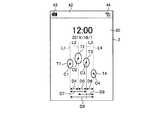
図1から図3を参照しながら、本実施形態に係るスマートフォン1の全体的な構成について説明する。図1から図3に示すように、スマートフォン1は、ハウジング20を有する。ハウジング20は、フロントフェイス1Aと、バックフェイス1Bと、サイドフェイス1C1〜1C4とを有する。フロントフェイス1Aは、ハウジング20の正面である。バックフェイス1Bは、ハウジング20の背面である。サイドフェイス1C1〜1C4は、フロントフェイス1Aとバックフェイス1Bとを接続する側面である。以下では、サイドフェイス1C1〜1C4を、どの面であるかを特定することなく、サイドフェイス1Cと総称することがある。
(Embodiment)
The overall configuration of thesmartphone 1 according to the present embodiment will be described with reference to FIGS. 1 to 3. As shown in FIGS. 1 to 3, thesmartphone 1 has ahousing 20. Thehousing 20 includes afront face 1A, aback face 1B, and side faces 1C1 to 1C4. Thefront face 1 </ b> A is the front of thehousing 20. Theback face 1 </ b> B is the back surface of thehousing 20. The side faces 1C1 to 1C4 are side surfaces that connect thefront face 1A and theback face 1B. Hereinafter, the side faces 1C1 to 1C4 may be collectively referred to as the side face 1C without specifying which face.

スマートフォン1は、タッチスクリーンディスプレイ2と、ボタン3A〜3Cと、照度センサ4と、近接センサ5と、レシーバ7と、マイク8と、カメラ12とをフロントフェイス1Aに有する。スマートフォン1は、スピーカ11と、カメラ13とをバックフェイス1Bに有する。スマートフォン1は、ボタン3D〜3Fと、コネクタ14とをサイドフェイス1Cに有する。以下では、ボタン3A〜3Fを、どのボタンであるかを特定することなく、ボタン3と総称することがある。  Thesmartphone 1 includes atouch screen display 2,buttons 3A to 3C, anilluminance sensor 4, aproximity sensor 5, areceiver 7, amicrophone 8, and acamera 12 on thefront face 1A. Thesmartphone 1 has aspeaker 11 and acamera 13 on theback face 1B. Thesmartphone 1 hasbuttons 3D to 3F and aconnector 14 on the side face 1C. Hereinafter, thebuttons 3A to 3F may be collectively referred to as thebutton 3 without specifying which button.

タッチスクリーンディスプレイ2は、ディスプレイ2Aと、タッチスクリーン2Bとを有する。ディスプレイ2Aは、液晶ディスプレイ(Liquid Crystal Display)、有機ELパネル(Organic Electro−Luminescence panel)、又は無機ELパネル(Inorganic Electro−Luminescence panel)等の表示デバイスを備える。ディスプレイ2Aは、文字、画像、記号又は図形等を表示する。  Thetouch screen display 2 includes adisplay 2A and atouch screen 2B. Thedisplay 2A includes a display device such as a liquid crystal display (Liquid Crystal Display), an organic EL panel (Organic Electro-Luminescence panel), or an inorganic EL panel (Inorganic Electro-Luminescence panel). Thedisplay 2A displays characters, images, symbols, graphics, and the like.

タッチスクリーン2Bは、タッチスクリーン2Bに対する指、ペン、又はスタイラスペン等の接触を検出する。タッチスクリーン2Bは、複数の指、ペン、又はスタイラスペン等がタッチスクリーン2Bに接触した位置を検出することができる。  Thetouch screen 2B detects contact of a finger, a pen, a stylus pen, or the like with respect to thetouch screen 2B. Thetouch screen 2B can detect a position where a plurality of fingers, a pen, a stylus pen, or the like is in contact with thetouch screen 2B.

タッチスクリーン2Bの検出方式は、静電容量方式、抵抗膜方式、表面弾性波方式(又は超音波方式)、赤外線方式、電磁誘導方式、及び荷重検出方式等の任意の方式でよい。以下では、説明を簡単にするため、タッチスクリーン2Bが接触を検出する指、ペン、又はスタイラスペン等は単に「指」ということがある。  The detection method of thetouch screen 2B may be any method such as a capacitance method, a resistive film method, a surface acoustic wave method (or an ultrasonic method), an infrared method, an electromagnetic induction method, and a load detection method. Hereinafter, for the sake of simplicity, a finger, pen, stylus pen, or the like that thetouch screen 2B detects contact may be simply referred to as a “finger”.

スマートフォン1は、タッチスクリーン2Bにより検出された接触、接触が検出された位置、接触が検出された間隔、及び接触が検出された回数の少なくとも1つに基づいてジェスチャの種別を判別する。ジェスチャは、タッチスクリーン2Bに対して行われる操作である。スマートフォン1によって判別されるジェスチャには、タッチ、ロングタッチ、リリース、スワイプ、タップ、ダブルタップ、ロングタップ、ドラッグ、フリック、ピンチイン、ピンチアウト等が含まれる。  Thesmartphone 1 determines the type of gesture based on at least one of the contact detected by thetouch screen 2B, the position at which the contact is detected, the interval at which the contact is detected, and the number of times the contact is detected. The gesture is an operation performed on thetouch screen 2B. The gesture discriminated by thesmartphone 1 includes touch, long touch, release, swipe, tap, double tap, long tap, drag, flick, pinch in, pinch out, and the like.

「タッチ」は、タッチスクリーン2Bに指が触れるジェスチャである。スマートフォン1は、タッチスクリーン2Bに指が接触するジェスチャをタッチとして判別する。「ロングタッチ」は、タッチスクリーン2Bに指が一定時間以上触れるジェスチャである。スマートフォン1は、タッチスクリーン2Bに指が一定時間以上接触するジェスチャをロングタッチとして判別する。  “Touch” is a gesture in which a finger touches thetouch screen 2B. Thesmartphone 1 determines a gesture in which a finger contacts thetouch screen 2B as a touch. “Long touch” is a gesture in which a finger touches thetouch screen 2B for a predetermined time or more. Thesmartphone 1 determines a gesture in which a finger is in contact with thetouch screen 2B for a predetermined time or more as a long touch.

「リリース」は、指がタッチスクリーン2Bから離れるジェスチャである。スマートフォン1は、指がタッチスクリーン2Bから離れるジェスチャをリリースとして判別する。「スワイプ」は、指がタッチスクリーン2Bに接触したままで移動するジェスチャである。スマートフォン1は、指がタッチスクリーン2Bに接触したままで移動するジェスチャをスワイプとして判別する。  “Release” is a gesture in which a finger leaves thetouch screen 2B. Thesmartphone 1 determines that a gesture in which a finger leaves thetouch screen 2B is a release. “Swipe” is a gesture in which a finger moves while touching thetouch screen 2B. Thesmartphone 1 determines a gesture that moves while the finger is in contact with thetouch screen 2B as a swipe.

「タップ」は、タッチに続いてリリースをするジェスチャである。スマートフォン1は、タッチに続いてリリースをするジェスチャをタップとして判別する。「ダブルタップ」は、タッチに続いてリリースをするジェスチャが2回連続するジェスチャである。スマートフォン1は、タッチに続いてリリースをするジェスチャが2回連続するジェスチャをダブルタップとして判別する。  A “tap” is a gesture for releasing following a touch. Thesmartphone 1 determines a gesture for releasing following a touch as a tap. The “double tap” is a gesture in which a gesture for releasing following a touch is continued twice. Thesmartphone 1 determines a gesture in which a gesture for releasing following a touch is continued twice as a double tap.

「ロングタップ」は、ロングタッチに続いてリリースをするジェスチャである。スマートフォン1は、ロングタッチに続いてリリースをするジェスチャをロングタップとして判別する。「ドラッグ」は、移動可能なオブジェクトが表示されている領域を始点としてスワイプをするジェスチャである。スマートフォン1は、移動可能なオブジェクトが表示されている領域を始点としてスワイプをするジェスチャをドラッグとして判別する。  “Long tap” is a gesture for releasing following a long touch. Thesmartphone 1 determines a gesture for releasing following a long touch as a long tap. “Drag” is a gesture for performing a swipe starting from an area where a movable object is displayed. Thesmartphone 1 determines, as a drag, a gesture for performing a swipe starting from an area where a movable object is displayed.

「フリック」は、タッチに続いて指が一方方向へ移動しながらリリースするジェスチャである。スマートフォン1は、タッチに続いて指が一方方向へ移動しながらリリースするジェスチャをフリックとして判別する。フリックの移動速度は、スワイプおよびドラッグの移動速度と比較して高速である。フリックは、指が画面の上方向へ移動する「上フリック」、指が画面の下方向へ移動する「下フリック」、指が画面の右方向へ移動する「右フリック」、指が画面の左方向へ移動する「左フリック」等を含む。  “Flick” is a gesture that is released while a finger moves in one direction following a touch. Thesmartphone 1 determines, as a flick, a gesture that is released while the finger moves in one direction following the touch. The movement speed of the flick is higher than the movement speed of the swipe and the drag. Flick is "upper flick" where the finger moves upward on the screen, "lower flick" where the finger moves downward on the screen, "right flick" where the finger moves rightward on the screen, finger is left on the screen Including “left flick” moving in the direction.

「ピンチイン」は、複数の指が近付く方向にスワイプするジェスチャである。スマートフォン1は、複数の指が近付く方向にスワイプするジェスチャをピンチインとして判別する。「ピンチアウト」は、複数の指が遠ざかる方向にスワイプするジェスチャである。スマートフォン1は、複数の指が遠ざかる方向にスワイプするジェスチャをピンチアウトとして判別する。  “Pinch-in” is a gesture of swiping in a direction in which a plurality of fingers approach. Thesmartphone 1 determines, as a pinch-in, a gesture that swipes in a direction in which a plurality of fingers approach. “Pinch out” is a gesture of swiping in a direction in which a plurality of fingers move away. Thesmartphone 1 determines a gesture of swiping in a direction in which a plurality of fingers move away as a pinch out.

スマートフォン1は、タッチスクリーン2Bを介して判別するこれらのジェスチャに従って動作を行う。このため、利用者にとって直感的で使いやすい操作性が実現される。判別されるジェスチャに従ってスマートフォン1が行う動作は、ディスプレイ2Aに表示されている画面に応じて異なる。以下では、説明を簡単にするために、「タッチスクリーン2Bがジェスチャを検出し、検出されたジェスチャの種別をスマートフォン1がXと判別すること」を、「スマートフォン1がXを検出する」、又は「コントローラがXを検出する」と記載することがある。  Thesmartphone 1 operates according to these gestures that are determined via thetouch screen 2B. Therefore, an operability that is intuitive and easy to use for the user is realized. The operation performed by thesmartphone 1 according to the determined gesture differs depending on the screen displayed on thedisplay 2A. Hereinafter, in order to simplify the description, “thetouch screen 2B detects a gesture and thesmartphone 1 determines that the type of the detected gesture is X”, “thesmartphone 1 detects X”, or “The controller detects X” may be described.

図4を参照しながら、ディスプレイ2Aに表示されるホーム画面の例について説明する。図4は、ホーム画面の一例を示している。ホーム画面は、デスクトップ、又は待受画面と呼ばれることもある。ホーム画面は、ディスプレイ2Aに表示される。ホーム画面は、スマートフォン1にインストールされているアプリケーションのうち、どのアプリケーションを実行するかを利用者に選択させる画面である。スマートフォン1は、ホーム画面で選択されたアプリケーションをフォアグランドで実行する。フォアグランドで実行されるアプリケーションの画面は、ディスプレイ2Aに表示される。  An example of a home screen displayed on thedisplay 2A will be described with reference to FIG. FIG. 4 shows an example of the home screen. The home screen may be called a desktop or a standby screen. The home screen is displayed on thedisplay 2A. The home screen is a screen that allows the user to select which application to execute from among the applications installed in thesmartphone 1. Thesmartphone 1 executes the application selected on the home screen in the foreground. The screen of the application executed in the foreground is displayed on thedisplay 2A.

スマートフォン1は、ホーム画面にアイコンを配置することができる。図4に示すホーム画面40には、複数のアイコン50が配置されている。それぞれのアイコン50は、スマートフォン1にインストールされているアプリケーションと予め対応付けられている。スマートフォン1は、アイコン50に対するジェスチャを検出すると、そのアイコン50に対応付けられているアプリケーションを実行する。例えば、スマートフォン1は、メールアプリケーションに対応付けられたアイコン50に対するタップが検出されると、メールアプリケーションを実行する。  Thesmartphone 1 can place an icon on the home screen. A plurality oficons 50 are arranged on thehome screen 40 shown in FIG. Eachicon 50 is associated with an application installed in thesmartphone 1 in advance. When thesmartphone 1 detects a gesture for theicon 50, thesmartphone 1 executes an application associated with theicon 50. For example, thesmartphone 1 executes the mail application when a tap on theicon 50 associated with the mail application is detected.

アイコン50は、画像と文字列を含む。アイコン50は、画像に代えて、記号又は図形を含んでもよい。アイコン50は、画像又は文字列のいずれか一方を含まなくてもよい。アイコン50は、配置パターンに基づいて配置される。アイコン50の背後には、壁紙41が表示される。壁紙は、フォトスクリーン又はバックスクリーンと呼ばれることもある。スマートフォン1は、任意の画像を壁紙41として用いることができる。利用者の設定に従って任意の画像が壁紙41として決定されてもよい。  Theicon 50 includes an image and a character string. Theicon 50 may include a symbol or a graphic instead of the image. Theicon 50 may not include either an image or a character string. Theicons 50 are arranged based on the arrangement pattern. Awallpaper 41 is displayed behind theicon 50. The wallpaper is sometimes called a photo screen or a back screen. Thesmartphone 1 can use any image as thewallpaper 41. An arbitrary image may be determined as thewallpaper 41 according to the setting of the user.

スマートフォン1は、ホーム画面の数を増減することができる。スマートフォン1は、例えば、ホーム画面の数を利用者による設定に従って決定する。スマートフォン1は、ホーム画面の数が複数であっても、選択された1つをディスプレイ2Aに表示する。  Thesmartphone 1 can increase or decrease the number of home screens. For example, thesmartphone 1 determines the number of home screens according to the setting by the user. Thesmartphone 1 displays the selected one on thedisplay 2A even if there are a plurality of home screens.

スマートフォン1は、ホーム画面上に、1つ又は複数のロケータを表示する。ロケータの数は、ホーム画面の数と一致する。ロケータは、どのホーム画面が現在表示されているかを示す。現在表示されているホーム画面に対応するロケータは、他のロケータと異なる態様で表示される。  Thesmartphone 1 displays one or more locators on the home screen. The number of locators matches the number of home screens. The locator indicates which home screen is currently displayed. The locator corresponding to the currently displayed home screen is displayed in a manner different from other locators.

図4に示す例では、4つのロケータ51が表示されている。これは、ホーム画面40の数が4つであることを示す。さらに、図4に示す例では、左から2番目のシンボルが他のシンボルと異なる態様で表示されている。これは、現在、左から2番目のホーム画面がディスプレイ2Aに表示されていることを示している。  In the example shown in FIG. 4, fourlocators 51 are displayed. This indicates that the number ofhome screens 40 is four. Further, in the example shown in FIG. 4, the second symbol from the left is displayed in a manner different from other symbols. This indicates that the second home screen from the left is currently displayed on thedisplay 2A.

スマートフォン1は、ホーム画面を表示中にジェスチャを検出すると、ディスプレイ2Aに表示するホーム画面を切り替える。例えば、スマートフォン1は、右フリックを検出すると、ディスプレイ2Aに表示するホーム画面を1つ左のホーム画面に切り替える。例えば、スマートフォン1は、左フリックを検出すると、ディスプレイ2Aに表示するホーム画面を1つ右のホーム画面に切り替える。  When thesmartphone 1 detects a gesture while displaying the home screen, thesmartphone 1 switches the home screen displayed on thedisplay 2A. For example, when detecting a right flick, thesmartphone 1 switches the home screen displayed on thedisplay 2A to the left home screen. For example, when thesmartphone 1 detects a left flick, thesmartphone 1 switches the home screen displayed on thedisplay 2A to the right home screen.

ディスプレイ2Aの上端には、領域42が設けられている。領域42には、充電池の残量を示す残量マーク43、及び通信用の電波の電界強度を示す電波レベルマーク44が表示される。スマートフォン1は、領域42に、時刻、天気、実行中のアプリケーション、通信システムの種別、電話のステータス、装置のモード、装置に生じたイベント等を表示してもよい。このように、領域42は、利用者に対して各種の通知を行うために用いられる。領域42は、ホーム画面40以外の画面でも設けられることがある。領域42が設けられる位置は、ディスプレイ2Aの上端に限定されない。  Aregion 42 is provided at the upper end of thedisplay 2A. In thearea 42, a remainingamount mark 43 indicating the remaining amount of the rechargeable battery and a radiowave level mark 44 indicating the electric field strength of the communication radio wave are displayed. Thesmartphone 1 may display the time, weather, running application, communication system type, telephone status, device mode, event occurring in the device, and the like in thearea 42. As described above, thearea 42 is used for various notifications to the user. Thearea 42 may be provided on a screen other than thehome screen 40. The position where theregion 42 is provided is not limited to the upper end of thedisplay 2A.

ホーム画面40の上下方向は、ディスプレイ2Aに表示される文字または画像の上下方向を基準とした方向である。よって、ホーム画面40は、タッチスクリーンディスプレイ2の長手方向において領域42に近い側がホーム画面40の上側となり、領域42から遠い側がホーム画面40の下側となる。領域42において電波レベルマーク44が表示されている側がホーム画面40の右側であり、領域42において残量マーク43が表示されている側がホーム画面40の左側である。スマートフォン1は、ホーム画面40に表示される文字または画像の上下方向に基づいて、例えば、ホーム画面の左方向、斜め左上方向、斜め右上方向、右方向、斜め右下方向、および、斜め左下方向を決定する。  The vertical direction of thehome screen 40 is a direction based on the vertical direction of characters or images displayed on thedisplay 2A. Therefore, in thehome screen 40, the side closer to theregion 42 in the longitudinal direction of thetouch screen display 2 is the upper side of thehome screen 40, and the side far from theregion 42 is the lower side of thehome screen 40. The side where the radiowave level mark 44 is displayed in thearea 42 is the right side of thehome screen 40, and the side where the remainingamount mark 43 is displayed in thearea 42 is the left side of thehome screen 40. Based on the vertical direction of the characters or images displayed on thehome screen 40, thesmartphone 1 is, for example, the left direction, the diagonally upper left direction, the diagonally upper right direction, the right direction, the diagonally lower right direction, and the diagonally lower left direction of the home screen. To decide.

図4に示したホーム画面は、一例であり、各種の要素の形態、各種の要素の配置、ホーム画面の数、及びホーム画面での各種の操作の仕方等は上記の説明の通りでなくてもよい。  The home screen shown in FIG. 4 is an example, and the form of various elements, the arrangement of various elements, the number of home screens, and various operation methods on the home screen are not as described above. Also good.

図5は、スマートフォン1の構成を示すブロック図である。スマートフォン1は、タッチスクリーンディスプレイ2と、ボタン3と、照度センサ4と、近接センサ5と、通信ユニット6と、レシーバ7と、マイク8と、ストレージ9と、コントローラ10と、スピーカ11と、カメラ12及び13と、コネクタ14と、加速度センサ15と、方位センサ16と、ジャイロスコープ17とを有する。  FIG. 5 is a block diagram illustrating the configuration of thesmartphone 1. Thesmartphone 1 includes atouch screen display 2, abutton 3, anilluminance sensor 4, aproximity sensor 5, a communication unit 6, areceiver 7, amicrophone 8, astorage 9, acontroller 10, aspeaker 11, and a camera. 12 and 13, aconnector 14, anacceleration sensor 15, anorientation sensor 16, and agyroscope 17.

タッチスクリーンディスプレイ2は、上述したように、ディスプレイ2Aと、タッチスクリーン2Bとを有する。ディスプレイ2Aは、文字、画像、記号、又は図形等を表示する。タッチスクリーン2Bは、ジェスチャを検出する。  As described above, thetouch screen display 2 includes thedisplay 2A and thetouch screen 2B. Thedisplay 2A displays characters, images, symbols, graphics, or the like. Thetouch screen 2B detects a gesture.

ボタン3は、利用者によって操作される。ボタン3は、ボタン3A〜ボタン3Fを有する。コントローラ10はボタン3と協働することによってボタン3に対する操作を検出する。ボタン3に対する操作は、例えば、クリック、ダブルクリック、トリプルクリック、プッシュ、及びマルチプッシュである。  Thebutton 3 is operated by the user. Thebutton 3 includesbuttons 3A to 3F. Thecontroller 10 detects an operation on thebutton 3 by cooperating with thebutton 3. The operations on thebutton 3 are, for example, click, double click, triple click, push, and multi-push.

ボタン3A〜3Cは、例えば、ホームボタン、バックボタン、又はメニューボタンである。ボタン3Dは、例えば、スマートフォン1のパワーオン/オフボタンである。ボタン3Dは、スリープ/スリープ解除ボタンを兼ねてもよい。ボタン3E及び3Fは、例えば、音量ボタンである。  Thebuttons 3A to 3C are, for example, a home button, a back button, or a menu button. Thebutton 3D is, for example, a power on / off button of thesmartphone 1. Thebutton 3D may also serve as a sleep / sleep release button. Thebuttons 3E and 3F are volume buttons, for example.

照度センサ4は、照度を検出する。照度は、光の強さ、明るさ、又は輝度を示す。照度センサ4は、例えば、ディスプレイ2Aの輝度の調整に用いられる。近接センサ5は、近隣の物体の存在を非接触で検出する。近接センサ5は、例えば、タッチスクリーンディスプレイ2が顔に近付けられたことを検出する。照度センサ4及び近接センサ5は、一つのセンサとして構成されていてもよい。  Theilluminance sensor 4 detects illuminance. Illuminance indicates light intensity, brightness, or luminance. Theilluminance sensor 4 is used for adjusting the luminance of thedisplay 2A, for example. Theproximity sensor 5 detects the presence of a nearby object without contact. Theproximity sensor 5 detects that thetouch screen display 2 is brought close to the face, for example. Theilluminance sensor 4 and theproximity sensor 5 may be configured as one sensor.

通信ユニット6は、無線により通信する。通信ユニット6によって行われる通信方式は、無線通信規格である。無線通信規格として、例えば、2G、3G、4G等のセルラーフォンの通信規格がある。セルラーフォンの通信規格として、例えば、LTE(Long Term Evolution)、W−CDMA(Wideband Code Division Multiple Access)、CDMA2000、PDC(Personal Digital Cellular)、GSM(登録商標)(Global System for Mobile Communications)、PHS(Personal Handy−phone System)等がある。無線通信規格として、例えば、WiMAX(Worldwide Interoperability for Microwave Access)、IEEE802.11、Bluetooth(登録商標)、IrDA(Infrared Data Association)、NFC(Near Field Communication)等がある。通信ユニット6は、上述した通信規格の1つ又は複数をサポートしていてもよい。  The communication unit 6 communicates wirelessly. The communication method performed by the communication unit 6 is a wireless communication standard. Examples of wireless communication standards include cellular phone communication standards such as 2G, 3G, and 4G. As a cellular phone communication standard, for example, LTE (Long Term Evolution), W-CDMA (Wideband Code Multiple Access), CDMA2000, PDC (Personal Digital Cellular, GSM (registered trademark) mmloS) (Personal Handy-phone System). Examples of wireless communication standards include WiMAX (Worldwide Interoperability for Microwave Access), IEEE802.11, Bluetooth (registered trademark), IrDA (Infrared Data Association), NFC (NearFunel, etc.). The communication unit 6 may support one or more of the communication standards described above.

レシーバ7及びスピーカ11は、コントローラ10から送信される音声信号を音声として出力する。レシーバ7は、例えば、通話時に相手の声を出力するために用いられる。スピーカ11は、例えば、着信音及び音楽を出力するために用いられる。レシーバ7及びスピーカ11の一方が、他方の機能を兼ねてもよい。マイク8は、利用者等の音声を音声信号へ変換してコントローラ10へ送信する。  Thereceiver 7 and thespeaker 11 output the audio signal transmitted from thecontroller 10 as audio. Thereceiver 7 is used, for example, to output the other party's voice during a call. Thespeaker 11 is used for outputting a ring tone and music, for example. One of thereceiver 7 and thespeaker 11 may also function as the other. Themicrophone 8 converts the voice of the user or the like into a voice signal and transmits it to thecontroller 10.

ストレージ9は、プログラム及びデータを記憶する。ストレージ9は、コントローラ10の処理結果を一時的に記憶する作業領域としても利用される。ストレージ9は、半導体記憶デバイス、及び磁気記憶デバイス等の任意の非一過的(non−transitory)な記憶デバイスを含んでよい。ストレージ9は、複数の種類の記憶デバイスを含んでよい。ストレージ9は、メモリカード、光ディスク、又は光磁気ディスク等の可搬の記憶媒体と、記憶媒体の読み取り装置との組み合わせを含んでよい。  Thestorage 9 stores programs and data. Thestorage 9 is also used as a work area for temporarily storing the processing result of thecontroller 10. Thestorage 9 may include any non-transitory storage device such as a semiconductor storage device and a magnetic storage device. Thestorage 9 may include a plurality of types of storage devices. Thestorage 9 may include a combination of a portable storage medium such as a memory card, an optical disk, or a magneto-optical disk and a storage medium reader.

ストレージ9に記憶されるプログラムには、フォアグランド又はバックグランドで実行されるアプリケーションと、アプリケーションの動作を支援する制御プログラムとが含まれる。アプリケーションは、例えば、ディスプレイ2Aに画面を表示させ、タッチスクリーン2Bによって検出されるジェスチャに応じた処理をコントローラ10に実行させる。制御プログラムは、例えば、OSである。アプリケーション及び制御プログラムは、通信ユニット6による無線通信又は非一過的な記憶媒体を介してストレージ9にインストールされてもよい。  The programs stored in thestorage 9 include an application executed in the foreground or the background and a control program that supports the operation of the application. For example, the application displays a screen on thedisplay 2 </ b> A, and causes thecontroller 10 to execute processing corresponding to the gesture detected by thetouch screen 2 </ b> B. The control program is, for example, an OS. The application and the control program may be installed in thestorage 9 via wireless communication by the communication unit 6 or a non-transitory storage medium.

ストレージ9は、例えば、制御プログラム9A、メールアプリケーション9B、ブラウザアプリケーション9C、及び設定データ9Zを記憶する。メールアプリケーション9Bは、電子メール機能を提供する。電子メール機能は、例えば、電子メールの作成、送信、受信、及び表示等を可能にする。ブラウザアプリケーション9Cは、WEBブラウジング機能を提供する。WEBブラウジング機能は、例えば、WEBページの表示、及びブックマークの編集等を可能にする。設定データ9Zは、スマートフォン1の動作に関する各種の設定機能を提供する。例えば、設定データ9Zは、スマートフォン1のロック状態を解除する解除パターンを記憶している。解除パターンは、タッチスクリーン2Bに対する複数の接触の相対位置に対応する。ここで、複数の接触の相対位置は、利用者の複数の指に対応する複数の接触(タッチ)が検出されたタッチスクリーン2B上の接触位置の相対的な位置関係を示す。つまり、複数の接触の相対位置とは、接触位置の相対的な位置関係を示すパターンともいえる。  Thestorage 9 stores, for example, a control program 9A, amail application 9B, abrowser application 9C, and settingdata 9Z. Themail application 9B provides an electronic mail function. The e-mail function enables, for example, creation, transmission, reception, and display of an e-mail. Thebrowser application 9C provides a WEB browsing function. The WEB browsing function enables, for example, display of a WEB page and editing of a bookmark. The settingdata 9Z provides various setting functions related to the operation of thesmartphone 1. For example, the settingdata 9Z stores a release pattern for releasing the lock state of thesmartphone 1. The release pattern corresponds to the relative positions of a plurality of contacts on thetouch screen 2B. Here, the relative positions of the plurality of contacts indicate the relative positional relationship of the contact positions on thetouch screen 2B where the plurality of contacts (touch) corresponding to the plurality of fingers of the user are detected. That is, it can be said that the relative position of a plurality of contacts is a pattern indicating the relative positional relationship of the contact positions.

本実施形態において、設定データ9Zに記憶される解除パターンは、ロック状態の解除中に、利用者の複数の指が揃った状態でタッチスクリーン2Bにより検出された複数の接触に基づいて設定される。例えば、スマートフォン1は、特定のボタン3がクリックされる等の所定の操作が検出されると、解除パターンを登録するための登録画面をディスプレイ2Aに表示する。ここで、利用者が登録画面上で複数の指を揃えた状態でタッチスクリーン2Bをタッチすると、スマートフォン1は、複数の指に対応する接触位置に基づいて、後述する図7〜図11に示すような、接触領域の中心座標、各中心座標間の距離、各中心座標を通る各平行線間の距離、隣接する接触領域間で算出される角度、および、各接触領域の面積の相対比等を算出し、これらのうち少なくとも1つに基づいて、接触位置の相対的な位置関係を示すパターンとして、解除パターンを登録する。  In the present embodiment, the release pattern stored in the settingdata 9Z is set based on a plurality of contacts detected by thetouch screen 2B in a state where a plurality of fingers of the user are aligned while releasing the locked state. . For example, when a predetermined operation such as clicking on aspecific button 3 is detected, thesmartphone 1 displays a registration screen for registering a release pattern on thedisplay 2A. Here, when the user touches thetouch screen 2B in a state where a plurality of fingers are aligned on the registration screen, thesmartphone 1 is shown in FIGS. 7 to 11 to be described later based on the contact positions corresponding to the plurality of fingers. Such as the center coordinates of the contact area, the distance between each center coordinate, the distance between each parallel line passing through each center coordinate, the angle calculated between adjacent contact areas, the relative ratio of the areas of each contact area, etc. Based on at least one of them, the release pattern is registered as a pattern indicating the relative positional relationship of the contact positions.

スマートフォン1は、解除パターンを登録する際、所定回数、利用者に同じ動作を促すようメッセージを登録画面上に表示してもよい。この場合、スマートフォン1は、1回目に登録した解除パターンと2回目に登録した解除パターンが異なる場合、解除パターンの設定をやり直すメッセージを登録画面上に表示する。例えば、利用者が1回目の登録において、指を揃えた状態で登録画面をタッチしたが、2回目の登録において、指を広げた状態で登録画面をタッチした場合、スマートフォン1は、解除パターンの設定をやり直すメッセージを登録画面上に表示してもよい。また、スマートフォン1は、所定回数登録された解除パターンの平均を最適な解除パターンとして登録してもよい。このようにして登録された解除パターンは、スマートフォン1がロック状態を解除する際に参照される。  When registering the release pattern, thesmartphone 1 may display a message on the registration screen so as to prompt the user to perform the same operation a predetermined number of times. In this case, when the cancellation pattern registered for the first time is different from the cancellation pattern registered for the second time, thesmartphone 1 displays a message for resetting the cancellation pattern on the registration screen. For example, when the user touches the registration screen with the fingers aligned in the first registration, but touches the registration screen with the fingers spread out in the second registration, thesmartphone 1 uses the release pattern. A message for re-setting may be displayed on the registration screen. Further, thesmartphone 1 may register the average of the cancellation patterns registered a predetermined number of times as the optimal cancellation pattern. The release pattern registered in this way is referred to when thesmartphone 1 releases the locked state.

制御プログラム9Aは、スマートフォン1を稼働させるための各種制御に関する機能を提供する。制御プログラム9Aは、例えば、通信ユニット6、レシーバ7、及びマイク8等を制御することによって、通話を実現させる。制御プログラム9Aが提供する機能には、ロック画面を表示する機能と、ロック状態において、タッチスクリーンディスプレイ2に対する複数の接触が検出された場合、当該検出された複数の接触の相対位置に基づいて、ロック状態を解除する機能とが含まれる。制御プログラム9Aが提供する機能は、メールアプリケーション9B等の他のプログラムが提供する機能と組み合わせて利用されることがある。  The control program 9A provides functions related to various controls for operating thesmartphone 1. The control program 9A realizes a call by controlling the communication unit 6, thereceiver 7, themicrophone 8, and the like, for example. The functions provided by the control program 9A include a function for displaying a lock screen, and when a plurality of contacts to thetouch screen display 2 are detected in the locked state, based on the relative positions of the detected plurality of contacts, And a function for releasing the lock state. The function provided by the control program 9A may be used in combination with a function provided by another program such as themail application 9B.

コントローラ10は、演算回路である。演算回路は、例えば、CPU(Central Processing Unit)、SoC(System−on−a−chip)、MCU(Micro Control Unit)、又はFPGA(Field−Programmable Gate Array)である。コントローラ10は、スマートフォン1の動作を統括的に制御して各種の機能を実現する。  Thecontroller 10 is an arithmetic circuit. The arithmetic circuit is, for example, a CPU (Central Processing Unit), an SoC (System-on-a-chip), an MCU (Micro Control Unit), or an FPGA (Field-Programmable Gate Array). Thecontroller 10 controls various operations of thesmartphone 1 to realize various functions.

具体的には、コントローラ10は、ストレージ9に記憶されているデータを必要に応じて参照しつつ、ストレージ9に記憶されているプログラムに含まれる命令を実行する。そして、コントローラ10は、データ及び命令に応じて機能部を制御し、それによって各種機能を実現する。コントローラ10は、検出部の検出結果に応じて、制御を変更することがある。機能部は、ディスプレイ2A、通信ユニット6、マイク8、及びスピーカ11を含むが、これらに限定されない。検出部は、タッチスクリーン2B、ボタン3、照度センサ4、近接センサ5、レシーバ7、カメラ12、カメラ13、加速度センサ15、方位センサ16、及びジャイロスコープ17を含むがこれらに限定されない。  Specifically, thecontroller 10 executes instructions included in the program stored in thestorage 9 while referring to the data stored in thestorage 9 as necessary. And thecontroller 10 controls a function part according to data and a command, and implement | achieves various functions by it. Thecontroller 10 may change the control according to the detection result of the detection unit. The functional unit includes thedisplay 2A, the communication unit 6, themicrophone 8, and thespeaker 11, but is not limited thereto. The detection unit includes, but is not limited to, thetouch screen 2B, thebutton 3, theilluminance sensor 4, theproximity sensor 5, thereceiver 7, thecamera 12, thecamera 13, theacceleration sensor 15, theazimuth sensor 16, and thegyroscope 17.

コントローラ10は、例えば、制御プログラム9Aを実行することにより、ロック状態において、タッチスクリーンディスプレイ2に対する複数の接触が検出された場合、当該検出された複数の接触の相対位置が条件を満たした場合、ロック状態を解除する処理を実行する。  For example, when thecontroller 10 executes the control program 9A to detect a plurality of contacts on thetouch screen display 2 in the locked state, the relative position of the detected plurality of contacts satisfies the condition. Execute the process to release the lock state.

カメラ12は、フロントフェイス1Aに面している物体を撮影するインカメラである。カメラ13は、バックフェイス1Bに面している物体を撮影するアウトカメラである。  Thecamera 12 is an in-camera that captures an object facing thefront face 1A. Thecamera 13 is an out camera that captures an object facing theback face 1B.

コネクタ14は、他の装置が接続される端子である。コネクタ14は、USB(Universal Serial Bus)、HDMI(High−Definition Multimedia Interface)(登録商標)、ライトピーク(サンダーボルト(登録商標))、イヤホンマイクコネクタのような汎用的な端子であってもよい。コネクタ14は、Dockコネクタのような専用の端子でもよい。コネクタ14に接続される装置は、例えば、外部ストレージ、スピーカ、及び通信装置である。  Theconnector 14 is a terminal to which another device is connected. Theconnector 14 may be a general-purpose terminal such as USB (Universal Serial Bus), HDMI (High-Definition Multimedia Interface (registered trademark), Light Peak (Thunderbolt (registered trademark)), or an earphone microphone connector. . Theconnector 14 may be a dedicated terminal such as a dock connector. Devices connected to theconnector 14 are, for example, an external storage, a speaker, and a communication device.

加速度センサ15は、スマートフォン1に働く加速度の方向及び大きさを検出する。方位センサ16は、地磁気の向きを検出する。ジャイロスコープ17は、スマートフォン1の角度及び角速度を検出する。加速度センサ15、方位センサ16及びジャイロスコープ17の検出結果は、スマートフォン1の位置及び姿勢の変化を検出するために、組み合わせて利用される。  Theacceleration sensor 15 detects the direction and magnitude of acceleration acting on thesmartphone 1. Thedirection sensor 16 detects the direction of geomagnetism. Thegyroscope 17 detects the angle and angular velocity of thesmartphone 1. The detection results of theacceleration sensor 15, theazimuth sensor 16, and thegyroscope 17 are used in combination in order to detect changes in the position and orientation of thesmartphone 1.

図5においてストレージ9が記憶するプログラムの一部又は全部は、通信ユニット6による無線通信で他の装置からダウンロードされてもよい。図5においてストレージ9が記憶するプログラムの一部又は全部は、ストレージ9に含まれる読み取り装置が読み取り可能な非一過的な記憶媒体に記憶されていてもよい。図5においてストレージ9が記憶するプログラムの一部又は全部は、コネクタ14に接続される読み取り装置が読み取り可能な非一過的な記憶媒体に記憶されていてもよい。非一過的な記憶媒体は、例えば、CD(登録商標)、DVD(登録商標)、Blu−ray(登録商標)等の光ディスク、光磁気ディスク、又はメモリカードである。  5 may be downloaded from another device through wireless communication by the communication unit 6. 5 may be stored in a non-transitory storage medium that can be read by a reading device included in thestorage 9. 5 may be stored in a non-transitory storage medium that can be read by the reading device connected to theconnector 14. The non-transitory storage medium is, for example, an optical disc such as a CD (registered trademark), a DVD (registered trademark), or a Blu-ray (registered trademark), a magneto-optical disk, or a memory card.

図5に示したスマートフォン1の構成は一例であり、本出願の要旨を損なわない範囲において適宜変更してよい。例えば、ボタン3の数と種類は図5の例に限定されない。スマートフォン1は、画面に関する操作のためのボタンとして、ボタン3A〜3Cに代えて、テンキー配列又はQWERTY配列等のボタンを備えていてもよい。スマートフォン1は、画面に関する操作のために、ボタンを1つだけ備えてよいし、ボタンを備えなくてもよい。図5に示した例では、スマートフォン1が2つのカメラを備えるが、スマートフォン1は、1つのカメラのみを備えてもよいし、カメラを備えなくてもよい。図5に示した例では、スマートフォン1が位置及び姿勢を検出するために3種類のセンサを備えるが、スマートフォン1は、このうちいくつかのセンサを備えなくてもよい。あるいは、スマートフォン1は、位置及び姿勢の少なくとも一つを検出するための他の種類のセンサを備えてもよい。  The configuration of thesmartphone 1 illustrated in FIG. 5 is an example, and may be appropriately changed within a range that does not impair the gist of the present application. For example, the number and type ofbuttons 3 are not limited to the example of FIG. Thesmartphone 1 may include buttons such as a numeric keypad layout or a QWERTY layout as buttons for operations related to the screen instead of thebuttons 3A to 3C. Thesmartphone 1 may include only one button or may not include a button for operations related to the screen. In the example illustrated in FIG. 5, thesmartphone 1 includes two cameras, but thesmartphone 1 may include only one camera or may not include a camera. In the example illustrated in FIG. 5, thesmartphone 1 includes three types of sensors in order to detect the position and orientation, but thesmartphone 1 may not include some of these sensors. Alternatively, thesmartphone 1 may include another type of sensor for detecting at least one of a position and a posture.

図6から図12を参照しながら、制御プログラム9Aが提供する機能に基づく制御の例について説明する。制御プログラム9Aが提供する機能には、ロック状態において、タッチスクリーンディスプレイ2に対する複数の接触が検出された場合、当該検出された複数の接触の相対位置に基づいて、ロック状態を解除する機能が含まれる。以下に、ロック状態が設定されている間に利用者の指示に従って実行される制御の例を示す。  An example of control based on the function provided by the control program 9A will be described with reference to FIGS. The function provided by the control program 9A includes a function of releasing the locked state based on the relative positions of the detected plurality of contacts when a plurality of contacts with thetouch screen display 2 are detected in the locked state. It is. The following is an example of control executed in accordance with a user instruction while the lock state is set.

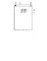
ここで、図6を用いて、ロック画面の例について説明する。ロック画面は、スマートフォン1がロックされていることを示す画面である。スマートフォン1は、例えば、タッチスクリーンディスプレイ2またはボタン3等に対する操作が行われずに所定の時間が経過するとロックされる。スマートフォン1は、例えば、スマートフォン1のスリープ/スリープ解除ボタンであるボタン3Dがクリックされた場合にもロックされる。スマートフォン1は、ロックされると、ロック状態を解除するために予め設定された操作が行われた場合にのみ、各種機能を実行することが可能な状態となる。  Here, an example of the lock screen will be described with reference to FIG. The lock screen is a screen indicating that thesmartphone 1 is locked. For example, thesmartphone 1 is locked when a predetermined time elapses without an operation on thetouch screen display 2 or thebutton 3 or the like. Thesmartphone 1 is also locked when, for example, abutton 3D that is a sleep / sleep release button of thesmartphone 1 is clicked. When thesmartphone 1 is locked, thesmartphone 1 is in a state where various functions can be executed only when a preset operation is performed to release the locked state.

スマートフォン1は、ロックが解除されると、ロック画面を消去し、ロックされる直前にディスプレイ2Aに表示していた画面を再びディスプレイ2Aに表示する。例えば、スマートフォン1は、ホーム画面40をディスプレイ2Aに表示している状態でロックされた場合、ロックが解除されると、ホーム画面40を再びディスプレイ2Aに表示する。なお、スマートフォン1のロックが解除されたときにディスプレイ2Aに表示される画面は、ロックされる直前に表示していた画面と異なる画面であってもよい。  When the lock is released, thesmartphone 1 erases the lock screen, and displays the screen displayed on thedisplay 2A immediately before being locked on thedisplay 2A again. For example, when thesmartphone 1 is locked while thehome screen 40 is displayed on thedisplay 2A, thesmartphone 1 displays thehome screen 40 on thedisplay 2A again when the lock is released. Note that the screen displayed on thedisplay 2A when thesmartphone 1 is unlocked may be a screen different from the screen displayed immediately before being locked.

図6は、ディスプレイ2Aに表示されたロック画面60を示す図である。図6に示すように、スマートフォン1は、ディスプレイ2Aにロック画面60および領域42を表示している。領域42は、図4と同様に、ディスプレイ2Aの上端に表示される。ロック画面60には、日付および時刻が領域42の下側に表示されている。スマートフォン1は、領域42を、ロック画面60と一緒に表示しなくてもよい。  FIG. 6 is a diagram showing thelock screen 60 displayed on thedisplay 2A. As shown in FIG. 6, thesmartphone 1 displays alock screen 60 and aregion 42 on thedisplay 2A. Thearea 42 is displayed at the upper end of thedisplay 2A as in FIG. On thelock screen 60, the date and time are displayed below thearea 42. Thesmartphone 1 may not display thearea 42 together with thelock screen 60.

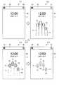
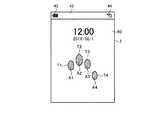
図7は、実施形態に係るスマートフォンが行う制御の第1の例を示す図である。この第1の例では、スマートフォン1は、タッチスクリーン2Bによって複数の接触が検出された各接触領域の中心点に対応する各中心座標に基づいて決定された相対位置のパターンを、上記の解除パターンとして設定している。  FIG. 7 is a diagram illustrating a first example of control performed by the smartphone according to the embodiment. In this first example, thesmartphone 1 uses the above-described release pattern as the relative position pattern determined based on the center coordinates corresponding to the center point of each contact area where a plurality of contacts are detected by thetouch screen 2B. It is set as.

スマートフォン1は、図7に示すように、ステップS11で、図6に示したロック画面60をディスプレイ2A(タッチスクリーンディスプレイ2)に表示している。  As shown in FIG. 7, thesmartphone 1 displays thelock screen 60 shown in FIG. 6 on thedisplay 2A (touch screen display 2) in step S11.

そして、ステップS12では、利用者が、4本の指(指F1、指F2、指F3、指F4)を揃えた状態で、タッチスクリーン2B(タッチスクリーンディスプレイ2)においてロック画面60が表示された部分をタッチしている。  In step S12, thelock screen 60 is displayed on thetouch screen 2B (touch screen display 2) with the user having four fingers (finger F1, finger F2, finger F3, finger F4) aligned. Touch the part.

この場合、スマートフォン1は、ロック画面60に対する複数の位置での接触を検出する。具体的には、スマートフォン1は、ロック画面60に対する複数の位置での接触を略同時に検出する。  In this case, thesmartphone 1 detects contact with thelock screen 60 at a plurality of positions. Specifically, thesmartphone 1 detects contact at a plurality of positions on thelock screen 60 substantially simultaneously.

本実施形態において、略同時とは、複数の指によるタッチが行われるとき、第1位置でのタッチが検出された時間と第2位置でのタッチが検出された時間との差が所定の時間間隔内である場合を含む概念である。つまり、スマートフォン1は、複数の位置でのタッチが厳密に同時に行われていない場合であっても、複数の位置でのタッチが検出された時間が所定の時間間隔内に収まっていれば、タッチスクリーンにおいて複数の位置が同時にタッチされたと判定する。例えば、スマートフォン1は、利用者が複数の指を順番にタッチスクリーンに置いた場合、つまり、複数の指による接触のタイミングがそれぞれずれた場合であっても、最初の指のタッチが検出された時間から最後の指のタッチが検出された時間が所定の時間間隔内であれば、複数の指が同時にタッチスクリーンに触れている状態にあると認識して、複数の接触として検出する。当然ながら、略同時とは、複数の位置でのタッチが同時に行われた場合、つまり、第1位置でのタッチが検出された時間と第2位置でのタッチが検出された時間との差がない場合も含む。  In the present embodiment, the term “substantially simultaneous” means that when a touch with a plurality of fingers is performed, the difference between the time when the touch at the first position is detected and the time when the touch at the second position is detected is a predetermined time. It is a concept including the case of being within an interval. In other words, even if the touches at a plurality of positions are not performed strictly at the same time, thesmartphone 1 touches if the time at which the touches at the plurality of positions are detected falls within a predetermined time interval. It is determined that a plurality of positions are touched simultaneously on the screen. For example, in thesmartphone 1, the first finger touch is detected even when the user places a plurality of fingers on the touch screen in order, that is, when the timing of contact with the plurality of fingers is shifted. If the time when the touch of the last finger is detected is within a predetermined time interval from the time, it is recognized that a plurality of fingers are simultaneously touching the touch screen, and detected as a plurality of contacts. Naturally, “substantially simultaneous” means that when touches at a plurality of positions are performed simultaneously, that is, the difference between the time when the touch at the first position is detected and the time when the touch at the second position is detected. Including the case where there is not.

スマートフォン1は、ロック画面60に対する複数の位置での接触を検出すると、ステップS13に示すように、各指F1〜指F4の略先端部分における略楕円形領域に対応する接触領域(タッチ点)T1〜T4を検出する。スマートフォン1は、利用者が4本の指F1〜F4の先端部分だけなく指の裏全体をタッチスクリーン2B上に置いた場合であっても、パターンマッチング技術等を利用して特徴点を抽出することにより、各指F1〜指F4の略先端部分における略楕円形領域に対応する接触領域(タッチ点)T1〜T4を検出することができる。  When thesmartphone 1 detects contact at a plurality of positions with respect to thelock screen 60, as shown in step S13, the contact area (touch point) T1 corresponding to the substantially elliptical area at the substantially distal end portion of each finger F1 to finger F4. ˜T4 is detected. Thesmartphone 1 extracts feature points using a pattern matching technique or the like even when the user places not only the tip portions of the four fingers F1 to F4 but the entire back of the finger on thetouch screen 2B. This makes it possible to detect contact areas (touch points) T1 to T4 corresponding to the substantially elliptical areas at the substantially tip portions of the fingers F1 to F4.

次に、スマートフォン1は、ステップS14に示すように、ステップS13で検出した各接触領域T1〜T4の中心点に対応する各中心座標C1〜C4を算出する。そして、スマートフォン1は、ステップS14で算出した各中心座標C1〜C4に基づいて複数の接触の相対位置(すなわち、複数の接触が検出されたタッチスクリーン2B上の接触位置の相対的な位置関係を示すパターン)を決定する。  Next, as shown in step S14, thesmartphone 1 calculates center coordinates C1 to C4 corresponding to the center points of the contact areas T1 to T4 detected in step S13. And thesmart phone 1 is based on each center coordinate C1-C4 calculated by step S14, The relative positional relationship of a some contact (namely, the relative positional relationship of the contact position on thetouch screen 2B from which the some contact was detected). Pattern to be determined).

その後、スマートフォン1は、決定した複数の接触の相対位置のパターンと、設定データ9Zに記憶された解除パターンと一致するか否かを判定して一致する場合は、ロック状態を解除する。スマートフォン1は、例えば、ディスプレイ2Aの表示をロック画面60から図4と同様のホーム画面40に変更する。  Thereafter, thesmartphone 1 determines whether or not the determined pattern of the relative positions of the plurality of contacts matches the release pattern stored in the settingdata 9Z, and releases the lock state if they match. For example, thesmartphone 1 changes the display on thedisplay 2 </ b> A from thelock screen 60 to thehome screen 40 similar to FIG. 4.

このように、スマートフォン1は、ロック画面60が複数の指を揃えた状態でタッチされている場合に、複数の指の各接触領域の中心点に対応する各中心座標により決定される相対位置のパターンに基づいて、スマートフォン1のロック状態を解除する。つまり、スマートフォン1は、決定された相対位置のパターンと所定条件とを比較し、決定された相対位置のパターンが所定条件を満たした場合、スマートフォン1のロック状態を解除する。これにより、スマートフォン1は、簡易なロック解除操作でロック状態を解除することができる。ここで、利用者の手の大きさ、指の太さ、長さは利用者ごとに異なるため、接触領域の中心点に対応する中心座標より決定される、複数の接触の相対位置も利用者ごとに異なる。よって、スマートフォン1は、利用者の判別を行うこともできセキュリティ性も確保することができる。このように、本実施形態によれば、セキュリティ性の確保とロック解除操作の操作性の向上とを両立させることができる。  As described above, when thelock screen 60 is touched with the plurality of fingers aligned, thesmartphone 1 has a relative position determined by each center coordinate corresponding to the center point of each contact area of the plurality of fingers. Based on the pattern, the locked state of thesmartphone 1 is released. That is, thesmartphone 1 compares the determined relative position pattern with a predetermined condition, and releases the locked state of thesmartphone 1 when the determined relative position pattern satisfies the predetermined condition. Thereby, thesmartphone 1 can release the locked state by a simple unlocking operation. Here, since the user's hand size, finger thickness, and length are different for each user, the relative position of a plurality of contacts determined by the center coordinates corresponding to the center point of the contact area is also determined by the user. Different for each. Therefore, thesmartphone 1 can determine the user and can secure the security. As described above, according to the present embodiment, it is possible to achieve both security and improved operability of the unlocking operation.

また、スマートフォン1は、接触位置の相対位置のパターンに基づいて、ロック解除を行うかを判定することで、タッチスクリーンディスプレイ2と複数の指との相対的な向きに影響を受けることなく判定を行うことができる。これにより、利用者は、スマートフォン1の向きを考慮せず、タッチスクリーンディスプレイ2に指を接触させるだけで、ロック状態を解除させることができる。  In addition, thesmartphone 1 can determine without being affected by the relative orientation of thetouch screen display 2 and the plurality of fingers by determining whether to perform unlocking based on the relative position pattern of the contact position. It can be carried out. Thereby, the user can cancel the locked state by simply touching thetouch screen display 2 with a finger without considering the orientation of thesmartphone 1.

図7に示す第1の例では、スマートフォン1は、ロック画面が4本の指を揃えた状態でタッチされるとロック状態を解除するが、本実施形態はこれに限られない。スマートフォン1は、利用者が、3本の指または2本の指を揃えた状態で、タッチスクリーン2B(タッチスクリーンディスプレイ2)においてロック画面60が表示された部分をタッチした場合も、設定データ9Zに記憶された解除パターンと、決定した相対位置のパターンとが部分一致するか否かを判定し、部分一致する場合、ロック状態を解除してもよい。  In the first example illustrated in FIG. 7, thesmartphone 1 releases the locked state when the lock screen is touched with four fingers aligned, but the present embodiment is not limited thereto. Even when the user touches a portion of thetouch screen 2B (touch screen display 2) where thelock screen 60 is displayed with three fingers or two fingers aligned, thesmartphone 1 also sets the settingdata 9Z. It is determined whether or not the release pattern stored in the part and the pattern of the determined relative position partially match, and if the part matches, the lock state may be released.

図8は、実施形態に係るスマートフォンが行う制御の第2の例を示す図である。この第2の例では、スマートフォン1は、各中心座標間の距離に基づいて決定された相対位置のパターンを、上記の解除パターンとして設定している。  FIG. 8 is a diagram illustrating a second example of control performed by the smartphone according to the embodiment. In the second example, thesmartphone 1 sets the relative position pattern determined based on the distance between the central coordinates as the release pattern.

図8に示すように、スマートフォン1は、上述の図7のステップS14で、タッチスクリーン2Bによって複数の接触が検出された各接触領域T1〜T4の中心点に対応する各中心座標C1〜C4を算出した後、算出した各中心座標間の距離D1〜D3を算出する。そして、スマートフォン1は、算出した各中心座標間の距離D1〜D3に基づいて複数の接触の相対位置を決定する。  As shown in FIG. 8, thesmartphone 1 stores the center coordinates C1 to C4 corresponding to the center points of the contact areas T1 to T4 in which a plurality of contacts are detected by thetouch screen 2B in step S14 of FIG. After the calculation, distances D1 to D3 between the calculated center coordinates are calculated. And thesmart phone 1 determines the relative position of a some contact based on the distance D1-D3 between each calculated center coordinate.

その後、スマートフォン1は、決定した複数の接触の相対位置のパターンと、設定データ9Zに記憶された解除パターンと一致するか否かを判定して一致する場合は、ロック状態を解除する。スマートフォン1は、例えば、ディスプレイ2Aの表示をロック画面60から図4と同様のホーム画面40に変更する。  Thereafter, thesmartphone 1 determines whether or not the determined pattern of the relative positions of the plurality of contacts matches the release pattern stored in the settingdata 9Z, and releases the lock state if they match. For example, thesmartphone 1 changes the display on thedisplay 2 </ b> A from thelock screen 60 to thehome screen 40 similar to FIG. 4.

このように、スマートフォン1は、ロック画面60が複数の指を揃えた状態でタッチされている場合に、複数の指の各接触領域の中心点に対応する各中心座標間の距離により決定される相対位置のパターンに基づいて、スマートフォン1のロック状態を解除する。これにより、スマートフォン1は、上記第1の例により決定された相対位置のパターンと、この第2の例により決定された相対位置のパターンとを適宜組み合わせることで、利用者ごとの識別精度を向上させることができ、その結果、セキュリティ性をさらに向上させることができる。  As described above, when thelock screen 60 is touched with the plurality of fingers aligned, thesmartphone 1 is determined by the distance between the center coordinates corresponding to the center points of the contact areas of the plurality of fingers. Based on the relative position pattern, thesmartphone 1 is unlocked. Thereby, thesmartphone 1 improves the identification accuracy for each user by appropriately combining the relative position pattern determined in the first example and the relative position pattern determined in the second example. As a result, the security can be further improved.

図8に示す第2の例では、スマートフォン1は、各中心座標間の距離として、C1とC2との間の距離D1、C2とC3との間の距離D2、C3とC4との間の距離D3を算出するが、本実施形態はこれに限られない。スマートフォン1は、C1とC3との距離、C1とC4との距離、C2とC4との距離も、各中心座標間の距離として算出して、これらの距離に基づいて相対位置を決定してもよい。  In the second example shown in FIG. 8, thesmartphone 1 has a distance D1 between C1 and C2, a distance D2 between C2 and C3, and a distance between C3 and C4 as distances between the central coordinates. Although D3 is calculated, this embodiment is not limited to this. Thesmartphone 1 calculates the distance between C1 and C3, the distance between C1 and C4, and the distance between C2 and C4 as the distance between the central coordinates, and determines the relative position based on these distances. Good.

図9は、実施形態に係るスマートフォンが行う制御の第3の例を示す図である。この第3の例では、スマートフォン1は、各中心座標を通る各平行線間の距離に基づいて決定された相対位置のパターンを、上記の解除パターンとして設定している。  FIG. 9 is a diagram illustrating a third example of control performed by the smartphone according to the embodiment. In the third example, thesmartphone 1 sets the pattern of the relative position determined based on the distance between the parallel lines passing through the center coordinates as the release pattern.

図9に示すように、スマートフォン1は、上述の図7のステップS14で、各中心座標C1〜C4を算出した後、算出した各中心座標を通る各平行線L1〜L4を設定する。具体的には、スマートフォン1は、各中心座標C1〜C4を含む略楕円形の各接触領域T1〜T4の長手方向を検出し、各中心座標C1〜C4から長手方向に向かって延びる各直線が平行になるよう、各中心座標C1〜C4を通る各平行線L1〜L4を設定する。この際、スマートフォン1は、基準となる中心座標C1についてのみ接触領域T1の長手方向を検出し、当該中心座標C1から当該長手方向に向かって引いた直線を基準線として設定し、当該基準線に対して平行になるよう他の中心座標C2〜C4を通る他の平行線L2〜L4を設定してもよい。そして、スマートフォン1は、設定した各平行線L1〜L4の距離を算出する。そして、スマートフォン1は、算出した各平行線間の距離D4〜D9に基づいて複数の接触の相対位置を決定する。  As illustrated in FIG. 9, thesmartphone 1 sets the parallel lines L1 to L4 passing through the calculated center coordinates after calculating the center coordinates C1 to C4 in step S14 of FIG. 7 described above. Specifically, thesmartphone 1 detects the longitudinal direction of the substantially elliptical contact areas T1 to T4 including the center coordinates C1 to C4, and each straight line extending from the center coordinates C1 to C4 in the longitudinal direction is detected. The parallel lines L1 to L4 passing through the center coordinates C1 to C4 are set so as to be parallel. At this time, thesmartphone 1 detects the longitudinal direction of the contact area T1 only for the reference center coordinate C1, sets a straight line drawn from the central coordinate C1 toward the longitudinal direction as the reference line, and sets the reference line as the reference line. Other parallel lines L2 to L4 passing through other central coordinates C2 to C4 may be set so as to be parallel to each other. And thesmart phone 1 calculates the distance of each set parallel line L1-L4. Then, thesmartphone 1 determines the relative positions of the plurality of contacts based on the calculated distances D4 to D9 between the parallel lines.

その後、スマートフォン1は、決定した複数の接触の相対位置のパターンと、設定データ9Zに記憶された解除パターンと一致するか否かを判定して一致する場合は、ロック状態を解除する。スマートフォン1は、例えば、ディスプレイ2Aの表示をロック画面60から図4と同様のホーム画面40に変更する。  Thereafter, thesmartphone 1 determines whether or not the determined pattern of the relative positions of the plurality of contacts matches the release pattern stored in the settingdata 9Z, and releases the lock state if they match. For example, thesmartphone 1 changes the display on thedisplay 2 </ b> A from thelock screen 60 to thehome screen 40 similar to FIG. 4.

このように、スマートフォン1は、ロック画面60が複数の指を揃えた状態でタッチされている場合に、複数の指の各接触領域の中心点に対応する各中心座標を通る各平行線間の距離により決定された相対位置のパターンに基づいて、スマートフォン1のロック状態を解除する。これにより、スマートフォン1は、上記第1の例および上記第2の例により決定された相対位置のパターンと、この第3の例により決定された相対位置のパターンとを適宜組み合わせることで、利用者ごとの識別精度を向上させることができ、その結果、セキュリティ性をより一層向上させることができる。  Thus, when thesmartphone 1 is touched with thelock screen 60 in a state where a plurality of fingers are aligned, between the parallel lines passing through the center coordinates corresponding to the center points of the contact areas of the plurality of fingers. Based on the pattern of the relative position determined by the distance, thesmartphone 1 is unlocked. Thereby, thesmartphone 1 appropriately combines the pattern of the relative position determined by the first example and the second example with the pattern of the relative position determined by the third example. As a result, the accuracy of identification can be improved, and as a result, the security can be further improved.

図10は、実施形態に係るスマートフォンが行う制御の第4の例を示す図である。この第4の例では、スマートフォン1は、互いに距離が最も近い隣接する接触領域間で算出される角度に基づいて決定された相対位置のパターンを、上記の解除パターンとして設定している。  FIG. 10 is a diagram illustrating a fourth example of control performed by the smartphone according to the embodiment. In the fourth example, thesmartphone 1 sets a pattern of relative positions determined based on an angle calculated between adjacent contact areas that are closest to each other as the release pattern.

図10に示すように、スマートフォン1は、上述の図7のステップS14で、各中心座標C1〜C4を算出し、上述の図8で算出した各中心座標間の距離D1〜D3を算出し、更に、上述の図9で算出した各中心座標を通る各平行線L1〜L4を設定した後、互いに距離が最も近い隣接する接触領域を第1の接触領域(例えば、T1)および第2の接触領域(例えば、T2)として設定する。そして、スマートフォン1は、当該第1の接触領域の中心座標(例えば、C1)と当該第2の接触領域の中心座標(例えば、C2)を結ぶ第1の線分を算出する。そして、スマートフォン1は、当該第1の接触領域の中心座標(例えば、C1)から当該第2の接触領域の中心座標を通る平行線(例えば、L2)上で垂直に交わる第2の線分を算出する。そして、スマートフォン1は、当該第1の線分と第2の線分とがなす角度(例えば、α)を算出する。そして、スマートフォン1は、算出した互いに距離が最も近い隣接する接触領域間で算出される角度に基づいて、複数の接触の相対位置を決定する。なお、角度β、γについても、スマートフォン1は、上述と同様の処理により算出することができる。  As shown in FIG. 10, thesmartphone 1 calculates the center coordinates C1 to C4 in step S14 of FIG. 7 described above, calculates the distances D1 to D3 between the center coordinates calculated in FIG. Furthermore, after setting the parallel lines L1 to L4 that pass through the respective center coordinates calculated in FIG. 9, the adjacent contact areas that are closest to each other are defined as the first contact area (for example, T1) and the second contact. Set as a region (for example, T2). Then, thesmartphone 1 calculates a first line segment connecting the center coordinates (for example, C1) of the first contact area and the center coordinates (for example, C2) of the second contact area. Then, thesmartphone 1 calculates a second line segment that intersects perpendicularly on a parallel line (for example, L2) passing through the center coordinate of the second contact area from the center coordinate (for example, C1) of the first contact area. calculate. And thesmart phone 1 calculates the angle (for example, (alpha)) which the said 1st line segment and a 2nd line segment make. Then, thesmartphone 1 determines the relative positions of the plurality of contacts based on the calculated angles between the adjacent contact areas that are closest to each other. Note that thesmartphone 1 can also calculate the angles β and γ by the same processing as described above.

その後、スマートフォン1は、決定した複数の接触の相対位置のパターンと、設定データ9Zに記憶された解除パターンと一致するか否かを判定して一致する場合は、ロック状態を解除する。スマートフォン1は、例えば、ディスプレイ2Aの表示をロック画面60から図4と同様のホーム画面40に変更する。  Thereafter, thesmartphone 1 determines whether or not the determined pattern of the relative positions of the plurality of contacts matches the release pattern stored in the settingdata 9Z, and releases the lock state if they match. For example, thesmartphone 1 changes the display on thedisplay 2 </ b> A from thelock screen 60 to thehome screen 40 similar to FIG. 4.

このように、スマートフォン1は、ロック画面60が複数の指を揃えた状態でタッチされている場合に、互いに距離が最も近い隣接する接触領域間で算出される角度により決定された相対位置のパターンに基づいて、スマートフォン1のロック状態を解除する。これにより、スマートフォン1は、上記第1の例、上記第2の例、および、上記第3の例により決定された相対位置のパターンと、この第4の例により決定された相対位置のパターンとを適宜組み合わせることで、利用者ごとの識別精度をより向上させることができ、その結果、セキュリティ性をより一層向上させることができる。  Thus, when thesmartphone 1 is touched with thelock screen 60 aligned with a plurality of fingers, the pattern of relative positions determined by the angles calculated between adjacent contact areas that are closest to each other. Based on the above, the locked state of thesmartphone 1 is released. Thereby, thesmartphone 1 includes the relative position pattern determined by the first example, the second example, and the third example, and the relative position pattern determined by the fourth example. As appropriate, the identification accuracy for each user can be further improved, and as a result, the security can be further improved.

図11は、実施形態に係るスマートフォンが行う制御の第5の例を示す図である。この第5の例では、スマートフォン1は、各接触領域の面積の相対比に基づいて決定された相対位置のパターンを、上記の解除パターンとして設定している。  FIG. 11 is a diagram illustrating a fifth example of control performed by the smartphone according to the embodiment. In the fifth example, thesmartphone 1 sets the pattern of the relative position determined based on the relative ratio of the areas of the contact areas as the release pattern.

図11に示すように、スマートフォン1は、上述の図7のステップS13で、各指F1〜指F4の略先端部分における略楕円形領域に対応する各接触領域T1〜T4を検出した後、検出した各接触領域の面積A1〜A4を算出する。そして、コントローラ10は、算出した各接触領域の面積の相対比(例えば、A1を1とした場合、A2は1.2、A3は0.9、A4は0.8)に基づいて、複数の接触の相対位置を決定する。  As shown in FIG. 11, thesmartphone 1 detects, after detecting each contact region T1 to T4 corresponding to a substantially elliptical region at a substantially tip portion of each finger F1 to finger F4 in step S13 of FIG. 7 described above. The areas A1 to A4 of the contact areas are calculated. Thecontroller 10 calculates a plurality of contact areas based on a relative ratio (for example, when A1 is 1, A2 is 1.2, A3 is 0.9, and A4 is 0.8). Determine the relative position of the contact.

その後、スマートフォン1は、決定した複数の接触の相対位置と、設定データ9Zに記憶された解除パターンと一致するか否かを判定して一致する場合は、ロック状態を解除する。スマートフォン1は、例えば、ディスプレイ2Aの表示をロック画面60から図4と同様のホーム画面40に変更する。  Thereafter, thesmartphone 1 determines whether or not the determined relative positions of the plurality of contacts match the release pattern stored in the settingdata 9Z, and releases the lock state if they match. For example, thesmartphone 1 changes the display on thedisplay 2 </ b> A from thelock screen 60 to thehome screen 40 similar to FIG. 4.

このように、スマートフォン1は、ロック画面60が複数の指を揃えた状態でタッチされている場合に、各接触領域の面積の相対比に基づいて決定された相対位置のパターンに基づいて、スマートフォン1のロック状態を解除する。これにより、スマートフォン1は、上記第1の例、上記第2の例、上記第3の例、および、上記第4の例により決定された相対位置のパターンと、この第5の例により決定された相対位置のパターンとを適宜組み合わせることで、利用者ごとの識別精度をより向上させることができ、その結果、セキュリティ性をより一層向上させることができる。  Thus, when thesmartphone 1 is touched with thelock screen 60 aligned with a plurality of fingers, thesmartphone 1 is based on the relative position pattern determined based on the relative ratio of the areas of the contact regions. 1 lock state is released. Thus, thesmartphone 1 is determined by the fifth example and the relative position pattern determined by the first example, the second example, the third example, and the fourth example. By appropriately combining the relative position patterns, the identification accuracy for each user can be further improved, and as a result, the security can be further improved.

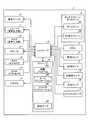
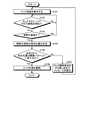
次に、図12を参照して、スマートフォン1がタッチスクリーン2Bにより検出される複数の接触の相対位置に基づいてロック状態を解除する処理手順について説明する。図12は、スマートフォン1のコントローラ10が行う制御を示すフローチャートである。コントローラ10は、図12に示す処理手順と並行して、他の処理手順を実行することがある。  Next, with reference to FIG. 12, a processing procedure in which thesmartphone 1 releases the locked state based on the relative positions of the plurality of contacts detected by thetouch screen 2B will be described. FIG. 12 is a flowchart showing the control performed by thecontroller 10 of thesmartphone 1. Thecontroller 10 may execute another processing procedure in parallel with the processing procedure shown in FIG.

まず、スマートフォン1のコントローラ10は、ステップS101として、ロック画面をディスプレイ2Aに表示する。そして、コントローラ10は、ステップS102に進む。  First, thecontroller 10 of thesmartphone 1 displays a lock screen on thedisplay 2A as step S101. Then, thecontroller 10 proceeds to step S102.

コントローラ10は、ステップS102で、タッチスクリーン2Bに対する接触が検出された否かを判定する。つまり、コントローラ10は、タッチスクリーン2Bに対するタッチが行われたか否かを判定する。コントローラ10は、タッチスクリーン2Bに対する接触が検出されなかったと判定した場合(ステップS102でNo)、ステップS102に進む。このように、コントローラ10は、ステップS102でタッチスクリーン2Bに対する接触が検出されたと判定されるまで、ステップS102の処理を繰り返す。  In step S102, thecontroller 10 determines whether contact with thetouch screen 2B is detected. That is, thecontroller 10 determines whether or not a touch on thetouch screen 2B has been performed. If thecontroller 10 determines that contact with thetouch screen 2B has not been detected (No in step S102), thecontroller 10 proceeds to step S102. Thus, thecontroller 10 repeats the process of step S102 until it determines with the contact with respect to thetouch screen 2B having been detected by step S102.

コントローラ10は、タッチスクリーン2Bに対する接触が検出されたと判定した場合(ステップS102でYes)、ステップS103に進む。コントローラ10は、ステップS103として、タッチスクリーン2Bによって検出された接触が複数であるか否かを判定する。つまり、コントローラ10は、タッチスクリーン2Bによって検出されたタッチが複数であるか否かを判定する。具体的には、ステップS103において、コントローラ10は、タッチスクリーン2Bによって略同時に検出された接触が複数であるか否かを判定する。ステップS103において、コントローラ10は、利用者の複数の指による接触のタイミングがそれぞれずれた場合であっても、最初の指のタッチが検出された時間から最後の指のタッチが検出された時間が所定の時間間隔内ある場合、複数の指が同時にタッチスクリーン2Bに触れている状態にあると認識して、接触が複数であると判定する。  If thecontroller 10 determines that contact with thetouch screen 2B has been detected (Yes in step S102), thecontroller 10 proceeds to step S103. As Step S103, thecontroller 10 determines whether or not there are a plurality of contacts detected by thetouch screen 2B. That is, thecontroller 10 determines whether there are a plurality of touches detected by thetouch screen 2B. Specifically, in step S103, thecontroller 10 determines whether or not there are a plurality of contacts detected substantially simultaneously by thetouch screen 2B. In step S <b> 103, thecontroller 10 determines whether the last finger touch is detected from the time when the first finger touch is detected, even when the timing of contact with the plurality of fingers of the user is shifted. If it is within the predetermined time interval, it is determined that a plurality of fingers are simultaneously touching thetouch screen 2B, and it is determined that there are a plurality of contacts.

コントローラ10は、タッチスクリーン2Bによって検出された接触が複数ではないと判定した場合(ステップS103でNo)、ステップS102に進む。このように、コントローラ10は、ステップS103でタッチスクリーン2Bによって検出された接触が複数であると判定されるまで、ステップS102〜S103の処理を繰り返す。  If thecontroller 10 determines that there are not a plurality of contacts detected by thetouch screen 2B (No in step S103), thecontroller 10 proceeds to step S102. As described above, thecontroller 10 repeats the processes in steps S102 to S103 until it is determined in step S103 that there are a plurality of contacts detected by thetouch screen 2B.

コントローラ10は、タッチスクリーン2Bによって検出された接触が複数であると判定した場合(ステップS103でYes)、ステップS104に進む。コントローラ10は、ステップS104として、タッチスクリーン2Bによって検出された複数の接触の相対位置を決定する。例えば、コントローラ10は、上述の図7〜図11に示した制御により、相対位置を決定する。そして、コントローラ10は、ステップS104で複数の接触の相対位置を決定した後、ステップS105に進む。  If thecontroller 10 determines that there are a plurality of contacts detected by thetouch screen 2B (Yes in step S103), thecontroller 10 proceeds to step S104. Thecontroller 10 determines the relative position of the some contact detected by thetouch screen 2B as step S104. For example, thecontroller 10 determines the relative position by the control shown in FIGS. Then, after determining the relative positions of the plurality of contacts in step S104, thecontroller 10 proceeds to step S105.

コントローラ10は、ステップS105として、ステップS104で決定された複数の接触の相対位置のパターンが、設定データ9Zに記憶された解除パターンと一致するか否かを判定する。ここで、コントローラ10は、ステップS104で決定された複数の接触の相対位置と解除パターンとの一致度を算出し、当該一致度が所定閾値以上であるか否かを判定することにより、設定データ9Zに記憶された解除パターンと一致するか否かを判定してもよい。  As Step S105, thecontroller 10 determines whether or not the pattern of the relative positions of the plurality of contacts determined in Step S104 matches the release pattern stored in the settingdata 9Z. Here, thecontroller 10 calculates the degree of coincidence between the relative positions of the plurality of contacts determined in step S104 and the release pattern, and determines whether or not the degree of coincidence is equal to or greater than a predetermined threshold value. You may determine whether it corresponds with the cancellation | release pattern memorize | stored in 9Z.

コントローラ10は、ステップS105で複数の接触の相対位置が解除パターンと一致すると判定した場合(ステップS105でYes)、ステップS106に進む。コントローラ10は、ステップS106として、スマートフォン1のロック状態を解除する。このとき、コントローラ10は、ディスプレイ2Aの表示を、ロック画面からロックされる直前にディスプレイ2Aに表示していた画面に変更する。  If thecontroller 10 determines in step S105 that the relative positions of the plurality of contacts match the release pattern (Yes in step S105), thecontroller 10 proceeds to step S106. Thecontroller 10 cancels the locked state of thesmartphone 1 as step S106. At this time, thecontroller 10 changes the display on thedisplay 2A to the screen displayed on thedisplay 2A immediately before being locked from the lock screen.

コントローラ10は、ステップS105で複数の接触の相対位置が解除パターンと一致しないと判定した場合(ステップS105でNo)ステップS107に進む。コントローラ10は、ステップS107として、スマートフォン1のロック状態を解除する操作をやり直すことを利用者に促すメッセージをディスプレイ2Aに表示する。そして、コントローラ10は、ステップS101に戻る。  If thecontroller 10 determines in step S105 that the relative positions of the plurality of contacts do not match the release pattern (No in step S105), thecontroller 10 proceeds to step S107. In step S107, thecontroller 10 displays a message prompting the user to redo the operation for releasing the lock state of thesmartphone 1 on thedisplay 2A. Then, thecontroller 10 returns to step S101.

スマートフォン1は、予め設定された利用者の指の相対位置の情報に基づいて、接触の相対位置の比較を行うことで、セキュリティ性を高くすることができる。ここで、スマートフォン1は、利用者の指の相対位置の情報を登録せずに、検出した接触の相対位置と代表的な人の指の接触の相対位置とを比較し、検出した接触の相対位置が人の指の接触であると判定した場合、ロック状態を解除するようにしてもよい。この場合、比較時に人の指であると判定する許容範囲は、上記実施形態の許容範囲よりも広くなる。  Thesmartphone 1 can increase the security by comparing the relative positions of the contacts based on information on the relative positions of the user's fingers set in advance. Here, thesmartphone 1 compares the relative position of the detected contact with the relative position of the contact of the representative person without registering the information on the relative position of the user's finger, and detects the relative position of the detected contact. When it is determined that the position is the contact of a person's finger, the lock state may be released. In this case, the allowable range for determining that the finger is a human finger at the time of comparison is wider than the allowable range of the above embodiment.

添付の請求項に係る技術を完全かつ明瞭に開示するために特徴的な実施形態に関し記載してきた。しかし、添付の請求項は、上記実施形態に限定されるべきものでなく、本明細書に示した基礎的事項の範囲内で当該技術分野の当業者が創作しうるすべての変形例及び代替可能な構成を具現化するように構成されるべきである。  The characterizing embodiments have been described in order to fully and clearly disclose the technology according to the appended claims. However, the appended claims should not be limited to the above-described embodiments, but all modifications and alternatives that can be created by those skilled in the art within the scope of the basic matters shown in this specification. Should be configured to embody such a configuration.

例えば、図5に示した各プログラムは、複数のモジュールに分割されていてもよい。あるいは、図5に示した各プログラムは、他のプログラムと結合されていてもよい。  For example, each program shown in FIG. 5 may be divided into a plurality of modules. Alternatively, each program shown in FIG. 5 may be combined with another program.

上記の実施形態では、タッチスクリーンを備える装置の一例として、スマートフォンについて説明したが、添付の請求項に係る装置は、スマートフォンに限定されない。添付の請求項に係る装置は、スマートフォン以外の携帯電子機器であってもよい。携帯電子機器は、例えば、モバイルフォン、タブレット、携帯型パソコン、デジタルカメラ、メディアプレイヤ、電子書籍リーダ、ナビゲータ、又はゲーム機である。あるいは、添付の請求項に係る装置は、据え置き型の電子機器であってもよい。据え置き型の電子機器は、例えば、デスクトップパソコン、及びテレビ受像器である。  In the above embodiment, a smartphone has been described as an example of a device including a touch screen, but the device according to the appended claims is not limited to a smartphone. The device according to the appended claims may be a portable electronic device other than a smartphone. The portable electronic device is, for example, a mobile phone, a tablet, a portable personal computer, a digital camera, a media player, an electronic book reader, a navigator, or a game machine. Alternatively, the device according to the appended claims may be a stationary electronic device. The stationary electronic devices are, for example, a desktop personal computer and a television receiver.

1 スマートフォン
2 タッチスクリーンディスプレイ
2A ディスプレイ
2B タッチスクリーン
3 ボタン
4 照度センサ
5 近接センサ
6 通信ユニット
7 レシーバ
8 マイク
9 ストレージ
9A 制御プログラム
9B メールアプリケーション
9C ブラウザアプリケーション
9Z 設定データ
10 コントローラ
11 スピーカ
12、13 カメラ
14 コネクタ
15 加速度センサ
16 方位センサ
17 ジャイロスコープ
20 ハウジング
DESCRIPTION OFSYMBOLS 1Smart phone 2Touch screendisplay 2A Display2B Touch screen 3Button 4Illuminance sensor 5 Proximity sensor 6Communication unit 7Receiver 8Microphone 9 Storage9A Control program9B Mail application9C Browser application9Z Setting data 10Controller 11Speaker 12, 13Camera 14Connector 15Acceleration sensor 16Direction sensor 17Gyroscope 20 Housing

Claims (11)

Translated fromJapanese
ロック画面を表示するタッチスクリーンディスプレイと、
ロック状態において、前記タッチスクリーンディスプレイに対する複数の接触が検出された場合、当該検出された複数の接触の相対位置に基づいて、前記ロック状態を解除するコントローラと、
を備える装置。
A touch screen display to display the lock screen;
A controller that releases the locked state based on a relative position of the detected plurality of contacts when a plurality of contacts to the touch screen display are detected in the locked state;
A device comprising:
前記コントローラは、前記複数の接触が検出された前記タッチスクリーンディスプレイ上の各接触領域の中心点に対応する各中心座標に基づいて、前記相対位置を決定する請求項1に記載の装置。  The apparatus according to claim 1, wherein the controller determines the relative position based on center coordinates corresponding to a center point of each contact area on the touch screen display where the plurality of contacts are detected. 前記コントローラは、前記複数の接触が検出された前記タッチスクリーンディスプレイ上の各接触領域の中心点に対応する各中心座標間の距離に基づいて、前記相対位置を決定する請求項1または2に記載の装置。  The said controller determines the said relative position based on the distance between each center coordinate corresponding to the center point of each contact area | region on the said touch screen display from which the said some contact was detected. Equipment. 前記コントローラは、前記複数の接触が検出された前記タッチスクリーンディスプレイ上の各接触領域の中心点に対応する各中心座標を通る平行線を設定し、設定した各平行線間の距離に基づいて、前記相対位置を決定する請求項1から3のうちいずれか一項に記載の装置。  The controller sets parallel lines passing through center coordinates corresponding to the center point of each contact area on the touch screen display where the plurality of contacts are detected, and based on the distance between the set parallel lines, The apparatus according to claim 1, wherein the relative position is determined. 前記コントローラは、前記複数の接触が検出された前記タッチスクリーンディスプレイ上の各接触領域の中心点に対応する各中心座標を通る平行線を設定し、互いに距離が最も近い隣接する接触領域を第1の接触領域および第2の接触領域として設定し、当該第1の接触領域の中心座標と当該第2の接触領域の中心座標を結ぶ第1の線分、および、当該第1の接触領域の中心座標から当該第2の接触領域の中心座標を通る平行線上で垂直に交わる第2の線分がなす角度に基づいて、前記相対位置を決定する請求項1から4のうちいずれか一項に記載の装置。  The controller sets parallel lines that pass through center coordinates corresponding to the center points of the contact areas on the touch screen display where the plurality of contacts are detected, and sets adjacent contact areas that are closest to each other as a first distance. A first line segment connecting the center coordinates of the first contact area and the center coordinates of the second contact area, and the center of the first contact area 5. The relative position is determined based on an angle formed by a second line segment perpendicularly intersecting on a parallel line passing through a center coordinate of the second contact area from the coordinates. Equipment. 前記コントローラは、前記複数の接触が検出された各接触領域の面積を算出し、算出した各接触領域の面積の相対比に基づいて、前記相対位置を決定する請求項1から5のうちいずれか一項に記載の装置。  6. The controller according to claim 1, wherein the controller calculates an area of each contact region where the plurality of contacts are detected, and determines the relative position based on a relative ratio of the calculated areas of the contact regions. The apparatus according to one item. 前記コントローラは、前記ロック状態において、前記タッチスクリーンディスプレイに対する複数の接触が検出された場合、当該検出された複数の接触の相対位置が人間の手の接触の相対位置と判定した場合に、前記ロック状態を解除する請求項1から6のうちいずれか一項に記載の装置。  In the locked state, the controller detects the lock when the plurality of contacts with the touch screen display are detected, and when the relative position of the detected plurality of contacts is determined to be the relative position of a human hand contact. The device according to any one of claims 1 to 6, wherein the state is released. 前記コントローラは、
前記ロック状態の解除中に、利用者の複数の指が揃った状態で前記タッチスクリーンディスプレイにより検出された複数の接触に基づいて、前記ロック状態を解除するための解除パターンを設定し、
前記ロック状態において、前記タッチスクリーンディスプレイに対する複数の接触が検出された場合、当該検出された複数の接触の相対位置と前記解除パターンとが一致した場合に、前記ロック状態を解除する請求項1から7のうちいずれか一項に記載の装置。
The controller is
Based on a plurality of touches detected by the touch screen display in a state where a plurality of fingers of the user are aligned during the release of the locked state, a release pattern for releasing the locked state is set.
The locked state is released when a plurality of contacts to the touch screen display are detected in the locked state, and a relative position of the detected plurality of contacts matches the release pattern. The apparatus according to any one of 7.
前記複数の接触は、3点以上の接触である請求項1から8のうちいずれか一項に記載の装置。  The apparatus according to claim 1, wherein the plurality of contacts are three or more contacts. タッチスクリーンディスプレイを備える装置を制御する方法であって、
ロック画面を前記タッチスクリーンディスプレイに表示させるステップと、
ロック状態において、前記タッチスクリーンディスプレイによって複数の接触が検出された場合、当該検出された複数の接触の相対位置に基づいて、前記ロック状態を解除するステップと、
を含む方法。
A method for controlling a device comprising a touch screen display, comprising:
Displaying a lock screen on the touch screen display;
When a plurality of contacts are detected by the touch screen display in the locked state, releasing the locked state based on the relative positions of the detected plurality of contacts;
Including methods.
タッチスクリーンディスプレイを備える装置に、
ロック画面を前記タッチスクリーンディスプレイに表示させるステップと、
ロック状態において、前記タッチスクリーンディスプレイによって複数の接触が検出された場合、当該検出された複数の接触の相対位置に基づいて、前記ロック状態を解除するステップと、
を実行させるプログラム。
For devices with touch screen displays,
Displaying a lock screen on the touch screen display;
When a plurality of contacts are detected by the touch screen display in the locked state, releasing the locked state based on the relative positions of the detected plurality of contacts;
A program that executes
JP2011286345A2011-12-272011-12-27Device, method, and programPendingJP2013134709A (en)

Priority Applications (1)

Application NumberPriority DateFiling DateTitle
JP2011286345AJP2013134709A (en)2011-12-272011-12-27Device, method, and program

Applications Claiming Priority (1)

Application NumberPriority DateFiling DateTitle
JP2011286345AJP2013134709A (en)2011-12-272011-12-27Device, method, and program

Publications (1)

Publication NumberPublication Date
JP2013134709Atrue JP2013134709A (en)2013-07-08

Family

ID=48911334

Family Applications (1)

Application NumberTitlePriority DateFiling Date
JP2011286345APendingJP2013134709A (en)2011-12-272011-12-27Device, method, and program

Country Status (1)

CountryLink
JP (1)JP2013134709A (en)

Cited By (1)

* Cited by examiner, † Cited by third party
Publication numberPriority datePublication dateAssigneeTitle
JP2016045553A (en)*2014-08-202016-04-04アルプス電気株式会社Information processing device, fingertip operation identification method thereof, and program

Citations (7)

* Cited by examiner, † Cited by third party
Publication numberPriority datePublication dateAssigneeTitle
JPS61105678A (en)*1984-10-291986-05-23Hitachi Ltd Personal authentication device
JP2004348522A (en)*2003-05-232004-12-09Nippon Telegr & Teleph Corp <Ntt> Hand shape authentication reference point detection method, hand shape authentication reference point detection device, program and recording medium
JP2006042880A (en)*2004-07-302006-02-16Fujitsu Ltd Biometric device guidance screen control method, biometric device and program thereof
JP2010173584A (en)*2009-01-302010-08-12Denso CorpOperating device
WO2011024584A1 (en)*2009-08-272011-03-03ソニー株式会社Information processing device, information processing method, and program
JP2011118456A (en)*2009-11-302011-06-16Toshiba CorpInformation processing apparatus and identification method of information processing apparatus
JP2011170603A (en)*2010-02-182011-09-01Fujitsu Toshiba Mobile Communications LtdPortable terminal

Patent Citations (8)

* Cited by examiner, † Cited by third party
Publication numberPriority datePublication dateAssigneeTitle
JPS61105678A (en)*1984-10-291986-05-23Hitachi Ltd Personal authentication device
JP2004348522A (en)*2003-05-232004-12-09Nippon Telegr & Teleph Corp <Ntt> Hand shape authentication reference point detection method, hand shape authentication reference point detection device, program and recording medium
JP2006042880A (en)*2004-07-302006-02-16Fujitsu Ltd Biometric device guidance screen control method, biometric device and program thereof
JP2010173584A (en)*2009-01-302010-08-12Denso CorpOperating device
WO2011024584A1 (en)*2009-08-272011-03-03ソニー株式会社Information processing device, information processing method, and program
JP2011048665A (en)*2009-08-272011-03-10Sony CorpApparatus and method for processing information and program
JP2011118456A (en)*2009-11-302011-06-16Toshiba CorpInformation processing apparatus and identification method of information processing apparatus
JP2011170603A (en)*2010-02-182011-09-01Fujitsu Toshiba Mobile Communications LtdPortable terminal

Cited By (1)

* Cited by examiner, † Cited by third party
Publication numberPriority datePublication dateAssigneeTitle
JP2016045553A (en)*2014-08-202016-04-04アルプス電気株式会社Information processing device, fingertip operation identification method thereof, and program

Similar Documents

PublicationPublication DateTitle
JP5775445B2 (en) Apparatus, method, and program
JP5715042B2 (en) Apparatus, method, and program
JP5972629B2 (en) Apparatus, method, and program
JP5891083B2 (en) Apparatus, method, and program
JP5809963B2 (en) Apparatus, method, and program
JP6159078B2 (en) Apparatus, method, and program
US9323444B2 (en)Device, method, and storage medium storing program
US9874994B2 (en)Device, method and program for icon and/or folder management
US20130162569A1 (en)Device, method, and computer-readable recording medium
JP5827109B2 (en) Apparatus, method, and program
JP2013047919A (en)Device, method, and program
JP2013257694A (en) Apparatus, method, and program
JP6483452B2 (en) Electronic device, control method, and control program
JP6058790B2 (en) Apparatus, method, and program
US20130162574A1 (en)Device, method, and storage medium storing program
JP2014071724A (en)Electronic apparatus, control method, and control program
JP6096100B2 (en) Electronic device, control method, and control program
JP5859932B2 (en) Apparatus, method, and program
JP5848971B2 (en) Apparatus, method, and program
JP5848970B2 (en) Apparatus, method, and program
JP2013101547A (en)Device, method, and program
JP2013134709A (en)Device, method, and program
JP2013182596A (en)Apparatus, method and program
JP2013092974A (en)Device, method, and program
JP2013073512A (en)Device, method, and program

Legal Events

DateCodeTitleDescription
A621Written request for application examination

Free format text:JAPANESE INTERMEDIATE CODE: A621

Effective date:20140514

A977Report on retrieval

Free format text:JAPANESE INTERMEDIATE CODE: A971007

Effective date:20150130

A131Notification of reasons for refusal

Free format text:JAPANESE INTERMEDIATE CODE: A131

Effective date:20150203

A521Written amendment

Free format text:JAPANESE INTERMEDIATE CODE: A523

Effective date:20150403

A131Notification of reasons for refusal

Free format text:JAPANESE INTERMEDIATE CODE: A131

Effective date:20150818

A521Written amendment

Free format text:JAPANESE INTERMEDIATE CODE: A523

Effective date:20151016

A02Decision of refusal

Free format text:JAPANESE INTERMEDIATE CODE: A02

Effective date:20151215


[8]ページ先頭

©2009-2025 Movatter.jp