JP2013133071A - Emergency blinking indicator lamp control device for vehicle - Google Patents
Emergency blinking indicator lamp control device for vehicleDownload PDFInfo
- Publication number
- JP2013133071A JP2013133071AJP2011286464AJP2011286464AJP2013133071AJP 2013133071 AJP2013133071 AJP 2013133071AJP 2011286464 AJP2011286464 AJP 2011286464AJP 2011286464 AJP2011286464 AJP 2011286464AJP 2013133071 AJP2013133071 AJP 2013133071A
- Authority
- JP
- Japan
- Prior art keywords
- emergency
- vehicle
- condition
- flashing
- lamp
- Prior art date
- Legal status (The legal status is an assumption and is not a legal conclusion. Google has not performed a legal analysis and makes no representation as to the accuracy of the status listed.)
- Pending
Links
- 230000004397blinkingEffects0.000titleclaimsabstractdescription65
- 238000001514detection methodMethods0.000claimsdescription5
- 230000001133accelerationEffects0.000description3
- 238000000034methodMethods0.000description3
- 230000005540biological transmissionEffects0.000description1
- 230000000881depressing effectEffects0.000description1
- 230000000994depressogenic effectEffects0.000description1
- 238000010586diagramMethods0.000description1
- 230000000694effectsEffects0.000description1
- 238000005516engineering processMethods0.000description1
- 238000012538light obscurationMethods0.000description1
- 238000012986modificationMethods0.000description1
- 230000004048modificationEffects0.000description1
- 230000001960triggered effectEffects0.000description1
Images


Landscapes
- Lighting Device Outwards From Vehicle And Optical Signal (AREA)
Abstract
Description
Translated fromJapanese本発明は、車両に装備された非常点滅表示灯を自動で消灯する車両の非常点滅表示灯制御装置に関するものである。 The present invention relates to an emergency flashing lamp control device for a vehicle that automatically turns off an emergency flashing lamp installed in a vehicle.
自動車(以下、車両ともいう)には、危険を他車両に伝えるために点滅させる非常点滅表示灯(所謂ハザードランプ)が装備される。この非常点滅表示灯の多くは左右の方向指示器のランプが利用され、非常点滅表示灯として作動する場合は、左右の方向指示器が同時に点滅する。 An automobile (hereinafter also referred to as a vehicle) is equipped with an emergency flashing indicator lamp (so-called hazard lamp) that flashes to convey danger to other vehicles. Many of these emergency flashing indicator lamps use the lamps of the left and right direction indicators, and when operating as emergency flashing indicator lights, the left and right direction indicators flash simultaneously.
非常点滅表示灯の作動は、運転者によるON/OFFスイッチ(所謂ハザードスイッチ)の操作によって手動で行なうが、所定の条件(非常点滅条件)下においては、非常点滅表示灯を自動で作動させる技術が開発されている。
この場合、非常点滅表示灯を自動で作動させる非常点滅条件としては、緊急制動表示灯の作動が停止した場合や、自車両が衝突事故にあった場合及びその他の衝突事故となるおそれがある場合が挙げられる。The operation of the emergency flashing indicator light is manually performed by the driver's operation of an ON / OFF switch (so-called hazard switch). Under a predetermined condition (emergency flashing condition), the emergency flashing indicator light is automatically operated. Has been developed.
In this case, the emergency flashing condition for automatically operating the emergency flashing indicator light is when the emergency braking indicator light stops operating, when the host vehicle is in a collision accident, or there is a risk of other collision accidents. Is mentioned.
緊急制動表示灯は、自車両の後方にある交通に自車両が急激に減速していることを示すものである。この緊急制動表示灯としては、制動灯を点滅作動させるもの、或いは、左右の方向指示器を非常点滅表示灯の点滅周期と異なる周期で点滅作動させるものを用いることができる。この緊急制動表示灯の作動に係る技術が、特許文献1に開示されている。
特許文献1の技術は、車両の減速度が所定の減速度を超えると制動灯を点滅作動させるものである。これにより、車両の減速度に応じて制動灯を制御し、後続車両の運転者に急減速状態を表示することができる。The emergency braking indicator light indicates that the host vehicle is decelerating rapidly in traffic behind the host vehicle. As this emergency brake indicator lamp, a lamp that blinks the brake lamp, or a lamp that activates the left and right direction indicators to blink at a cycle different from the blink cycle of the emergency blink indicator lamp can be used. A technique relating to the operation of the emergency braking indicator lamp is disclosed in Patent Document 1.
The technology of Patent Document 1 is to blink the brake lamp when the deceleration of the vehicle exceeds a predetermined deceleration. As a result, the brake light can be controlled according to the deceleration of the vehicle, and the rapid deceleration state can be displayed to the driver of the following vehicle.
ところで、非常点滅表示灯が自動で作動された場合、非常点滅表示灯を消灯するには、非常点滅表示灯のON/OFFスイッチを手動でOFF操作することが必要となる。 By the way, when the emergency flashing indicator lamp is automatically operated, it is necessary to manually turn off the ON / OFF switch of the emergency flashing indicator lamp to turn off the emergency flashing indicator lamp.
しかしながら、例えば一瞬だけ急ブレーキ操作を行なうことにより未然に危険を回避した状況等は、非常点滅条件に含まれうる緊急制動表示灯の作動が停止した場合に該当するため、非常点滅表示灯が自動で作動する場合がある。この場合、危険を他車両に伝える必要が無い状況にもかかわらず、運転者が非常点滅表示灯のOFF操作を忘れたまま、非常点滅表示灯を点滅作動させて車両を走行させてしまうおそれがある。 However, for example, the situation where the danger was avoided by suddenly operating the brake suddenly for a moment corresponds to the case where the operation of the emergency braking indicator light that can be included in the emergency flashing condition is stopped. May work on. In this case, the driver may forget to turn off the emergency flashing indicator light and drive the vehicle by flashing the emergency flashing indicator light in spite of the situation where it is not necessary to convey the danger to other vehicles. is there.
本発明は、かかる課題に鑑み創案されたものであり、非常点滅表示灯が自動で作動された場合に、非常点滅表示灯を適切に自動で消灯することができるようにした、車両の非常点滅表示灯制御装置を提供することを目的とする。 The present invention was devised in view of such a problem, and when an emergency flashing indicator light is automatically operated, the emergency flashing indicator light can be appropriately turned off automatically. An object is to provide an indicator light control device.
(1)上記の目的を達成するために、本発明の車両の非常点滅表示灯制御装置は、非常点滅条件が成立したか否かを判定し前記非常点滅条件が成立すれば非常点滅表示灯を自動で作動させる自動点滅手段と、前記自動点滅手段により前記非常点滅表示灯が自動で作動された場合に、運転者により車両の走行操作がされているか否かを判定し前記運転者による前記車両の走行操作がされていると判定すれば前記非常点滅表示灯を自動で消灯する自動消灯手段とを備えたことを特徴としている。 (1) In order to achieve the above object, the emergency flashing lamp control device for a vehicle according to the present invention determines whether or not the emergency flashing condition is satisfied, and if the emergency flashing condition is satisfied, An automatic flashing means that is automatically operated, and when the emergency flashing indicator lamp is automatically operated by the automatic flashing means, it is determined whether or not the vehicle is operated by the driver, and the vehicle by the driver If it is determined that the traveling operation is performed, an automatic turn-off means for automatically turning off the emergency flashing indicator lamp is provided.
(2)車速を検出する車速検出手段を備え、前記自動消灯手段は、前記車速検出手段により検出された車速が予め設定された所定車速よりも高ければ前記運転者により前記車両の走行操作がされていると判定することが好ましい。
(3)前記所定車速は、前記車両が停車後に空走した場合に到達する車速の上限値として予め設定されるが好ましい。(2) Vehicle speed detecting means for detecting the vehicle speed is provided, and the automatic turn-off means is operated by the driver when the vehicle speed detected by the vehicle speed detecting means is higher than a predetermined vehicle speed set in advance. It is preferable to determine that
(3) Preferably, the predetermined vehicle speed is set in advance as an upper limit value of a vehicle speed that is reached when the vehicle runs idle after stopping.
(4)前記運転者によるアクセル操作を検出するアクセル操作検出手段を備え、前記自動消灯手段は、前記アクセル操作検出手段によりアクセル操作が検出されれば前記運転者により前記車両の走行操作がされていると判定することが好ましい。
(5)前記非常点滅条件には、前記車両の停止が少なくとも含まれることが好ましい。(4) An accelerator operation detecting means for detecting an accelerator operation by the driver is provided, and the automatic turn-off means is configured such that if the accelerator operation is detected by the accelerator operation detecting means, the driving operation of the vehicle is performed by the driver. It is preferable to determine that it is present.
(5) It is preferable that the emergency blinking condition includes at least a stop of the vehicle.
本発明の車両の非常点滅表示灯制御装置によれば、自動消灯手段が、非常点滅表示灯が自動で作動された場合に運転者により車両の走行操作がされていれば前記非常点滅表示灯を自動で消灯するため、非常点滅表示灯が自動で作動された場合に運転者により車両の走行操作がされている状況では非常点滅表示灯が自動で消灯される。このため、非常点滅表示灯を適切に自動で消灯することができ、例えば、危険を他車両に伝える必要が無い状況にもかかわらず、運転者が非常点滅表示灯のOFF操作を忘れたまま、非常点滅表示灯を点滅させて車両を走行させることを防止することができる。 According to the emergency flashing indicator control device for a vehicle of the present invention, the automatic extinguishing means turns off the emergency flashing indicator if the driver is operating the vehicle when the emergency flashing indicator is automatically operated. Since it automatically turns off, the emergency flashing indicator light is automatically turned off when the driver is operating the vehicle when the emergency flashing indicator light is automatically activated. For this reason, the emergency flashing indicator light can be appropriately turned off automatically, for example, while the driver forgets to turn off the emergency flashing indicator light in spite of the situation where there is no need to convey the danger to other vehicles. It is possible to prevent the vehicle from running by blinking the emergency blinking indicator light.
以下、図面を用いて本発明の実施形態について説明する。
〈第1実施形態〉
[構成]Hereinafter, embodiments of the present invention will be described with reference to the drawings.
<First Embodiment>
[Constitution]
まず、第1実施形態にかかる車両の非常点滅表示灯制御装置の構成を説明する。なお、この非常点滅表示灯制御装置は、非常点滅表示灯自動点滅装置と非常点滅表示灯自動消灯装置とが併合された装置である。また、本実施形態にかかる車両は、例えばトラック又はバスといったいわゆる大型又は中型の自動車である。 First, the configuration of the emergency blinking indicator control device for a vehicle according to the first embodiment will be described. This emergency blinking indicator light control device is a device in which an emergency blinking indicator light automatic blinking device and an emergency blinking indicator light automatic extinguishing device are combined. The vehicle according to the present embodiment is a so-called large or medium-sized vehicle such as a truck or a bus.
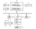
図1に示すように、本実施形態の非常点滅表示灯制御装置が装備される車両は、ESS(Emergency Stop Signal)ECU10と、エンジン(ENG)ECU20と、ブレーキECU30と、AEBS(Advanced Emergency Brake System)ECU40とを有する。これらのECU10,20,30,40は何れも、例えばマイクロプロセッサやROM,RAM等を集積したLSIデバイスや組み込み電子デバイスとして構成される電子制御装置であり、CAN(Controller Area Network)を介して相互に接続される。 As shown in FIG. 1, a vehicle equipped with the emergency flashing indicator control device of this embodiment includes an ESS (Emergency Stop Signal) ECU 10, an engine (ENG) ECU 20, a
ESSECU10は、非常点滅表示灯及び緊急制動表示灯の作動を制御するものである。
非常点滅表示灯とは、危険を他車両に伝えるために点滅させるものであり、ここでは左右の方向指示器のランプを第1の周期で同時に点滅させるハザードランプ5を意味する。
緊急制動表示灯とは、自車両の後方にある交通に自車両が急激に減速していることを示すものであり、第1の周期と異なる(通常、第1の周期よりも短い)第2の周期でハザードランプ5を点滅作動させるものである。なお、緊急制動表示灯として、制動灯を第2の周期で点滅作動させるものを用いてもよい。The ESS ECU 10 controls the operation of the emergency blinking indicator lamp and the emergency brake indicator lamp.
The emergency flashing indicator lamp flashes in order to convey the danger to other vehicles, and here means the
The emergency brake indicator light indicates that the host vehicle is rapidly decelerating in traffic behind the host vehicle, and is different from the first cycle (usually shorter than the first cycle). The
このESSECU10は、車速センサ(車速検出手段)1,ハザードスイッチ(SW)2及びハザードランプ5のそれぞれとワイヤーハーネスを介して接続される。
車速センサ1は、車速Vを検出するものである。この車速センサ1としては、図示しないトランスミッションの出力軸の回転数を検出するものを用いることができる。
車速センサ1により検出された車速Vの情報は、ESSECU10に伝達される。
ハザードスイッチ2は、ハザードランプ5を手動で操作するためのON/OFFスイッチである。The ESS ECU 10 is connected to each of a vehicle speed sensor (vehicle speed detection means) 1, a hazard switch (SW) 2 and a
The vehicle speed sensor 1 detects the vehicle speed V. As the vehicle speed sensor 1, a sensor that detects the rotational speed of the output shaft of a transmission (not shown) can be used.
Information on the vehicle speed V detected by the vehicle speed sensor 1 is transmitted to the ESS ECU 10.
The
運転者がハザードスイッチ2をON操作すれば、ハザードランプ5は非常点滅表示灯として点滅作動し、ハザードスイッチ2のON情報がESSECU10に伝達される。また、運転者がハザードスイッチ2をOFF操作すれば、ハザードランプ5は消灯し、ハザードスイッチ2のOFF情報がESSECU10に伝達される。
ハザードランプ5は、左右の方向指示器のランプを同時点滅させるものであり、非常点滅表示灯及び緊急制動表示灯として用いられる。
このハザードランプ5は、非常点滅表示灯として作動される場合には例えば1Hzに相当する第1の周期で点滅し、緊急制動表示灯として作動される場合には例えば4Hzに相当する第2の周期で点滅する。When the driver turns on the
The
When the
エンジンECU20は、図示しないエンジンの制御を行なうものであり、ブレーキスイッチ(SW)21とアクセルポジションセンサ(APS,アクセル操作検出手段)22とがワイヤーハーネスを介して接続される。 The
ブレーキスイッチ21は、運転者によるブレーキペダルの操作の有無を検出するものである。このブレーキスイッチ21は、運転者によるブレーキペダルの操作があればON状態となり、運転者によるブレーキペダルの操作がなければOFF状態となる。
ブレーキスイッチ21のON/OFF情報はエンジンECU20に伝達される。The
ON / OFF information of the
アクセルポジションセンサ22は、運転者によるアクセルペダルの踏込量θACCを検出するものである。
アクセルポジションセンサ22により検出されたアクセルペダルの踏込量θACCの情報はエンジンECU20に伝達される。The
Information on the accelerator pedal depression amount θACC detected by the
ブレーキECU30は、車両の制動装置の制御を行なうものであり、車輪速センサ31がワイヤーハーネスを介して接続される。
車輪速センサ31は、図示しない車輪の回転速度を検出するものである。
車輪速センサ31により検出された車輪の回転速度の情報はブレーキECU30に伝達される。
また、ブレーキECU30は、ABS(Antilock Brake System)ECU30aとEBS(Electronic Braking System)ECU30bとから構成される。The
The wheel speed sensor 31 detects a rotational speed of a wheel (not shown).
Information on the rotational speed of the wheel detected by the wheel speed sensor 31 is transmitted to the
The
ABSECU30aは、車輪のロックによる滑走を防止するABS制御を行なうものである。ABSECU30aによるABS制御では、車輪のロック状態を検知したら制動力を緩め、ロック状態を解除されたら制動力を復帰させる。
EBSECU30bは、ブレーキペダルと制動装置との間に電子制御装置を設け、ブレーキペダルの操作に応じて制動装置の制御を行なうものである。この制御では、例えば、車輪速センサ31により検出された車輪の回転速度の情報を用いて、運転者によるブレーキペダルのストローク量とこのストローク量に対応する減速度を演算し、実際に発生している減速度を目標の減速度と一致するように制動装置を作動させる。The
The
AEBSECU40は、先行車両や落下物といった車両の前方のものに衝突するおそれがある場合に、車両を制動する衝突被害軽減制動(AEBS)制御を行なうものである。
この衝突被害軽減制動制御は、図示しないミリ波レーダ等により検出された車間距離から算出された衝突余裕時間(TTC,Time To Collision)に基づいて実施され、例えば、車両とこの車両の前方のものとの相対速度や車間距離に基づいて推定される衝突余裕時間が所定時間以下になった場合に、車両が衝突するおそれがあるため、車両を制動し減速させるものである。なお、所定時間とは、車両において制動操作を行なっても衝突を回避することが困難な時間として予め実験的又は経験的に設定される。The
This collision damage reduction braking control is performed based on a collision margin time (TTC, Time To Collision) calculated from an inter-vehicle distance detected by a millimeter wave radar or the like (not shown). When the collision margin time estimated based on the relative speed and the inter-vehicle distance becomes equal to or shorter than a predetermined time, the vehicle may be collided, so that the vehicle is braked and decelerated. The predetermined time is set experimentally or empirically in advance as a time during which it is difficult to avoid a collision even when a braking operation is performed on the vehicle.
上記のECU20に伝達される種々の情報及びECU30,40による制御の実施情報は、ESSECU10に伝達される。
詳細には、ESSECU10には、ブレーキスイッチ21のON/OFF情報,アクセルポジションセンサ22により検出されたアクセルペダルの踏込量θACCの情報,ブレーキECU30のABSECU30aによりABS制御が実施されているか否かの情報,及びAEBSECU40により衝突被害軽減制動制御が実施されているか否かの情報が少なくとも伝達される。The various information transmitted to the
Specifically, the
また、ESSECU10は、車速センサ1から伝達された車速Vの情報に基づいて減速度(負の加速度)Gを算出する。
ESSECU10が有する緊急制動表示制御部11及び非常点滅表示制御部(自動点滅手段,自動消灯手段)12は、これらの情報に基づいてハザードランプ5の作動を制御する。The
The emergency braking
緊急制動表示制御部11は、緊急制動表示灯の作動を制御するものであり、緊急制動表示灯を自動で点滅作動(作動ON)させる緊急点滅制御と、作動ONされている緊急制動表示灯を自動で作動停止(作動OFF)させる緊急消灯制御とを行なう。
まず、緊急制動表示制御部11による緊急点滅制御について説明する。The emergency braking
First, emergency flashing control by the emergency braking
緊急点滅制御は、緊急制動時に緊急制動表示灯を自動で点滅作動させ、ハザードランプ5を第2の周期で点滅させるものである。この緊急制動表示制御部11は、緊急制動表示灯を自動で作動ONさせる条件(緊急点滅条件ともいう)が成立したか否かを判定し、緊急点滅条件が成立する場合を車両の緊急制動時としている。この緊急点滅条件は、緊急制動表示灯を自動で作動ONさせる作動開始条件である。
以下、図2を用いて緊急点滅条件を説明する。In the emergency flashing control, an emergency brake indicator lamp is automatically flashed during emergency braking, and the
Hereinafter, the emergency blinking condition will be described with reference to FIG.
図2に示すように、条件A11〜A16の理論和或いは理論積により緊急点滅条件が成立又は不成立となる。なお、これらの条件A11〜A16は、運転者或いはブレーキECU30により制動装置を作動させることによる緊急制動に着目した条件である。
条件A11は、ハザードスイッチ2がOFF操作されていることである。
条件A12は、車速Vが規定車速VRよりも高いことである。この規定車速VRは、例えば下記のように予め設定される。As shown in FIG. 2, the emergency blinking condition is established or not established depending on the theoretical sum or product of the conditions A11 to A16. In addition, these conditions A11-A16 are conditions which paid their attention to the emergency braking by operating a braking device by a driver | operator or brake ECU30.
Condition A11 is that the
Condition A12 is that the vehicle speed V is higher than the specified vehicle speed VR. The specified vehicle speed VR is set in advance as follows, for example.
緊急制動開始時の車速が低ければ、急ブレーキ操作といった緊急制動による後方の交通への影響が小さい。このため、緊急制動による後方の交通への影響が小さい場合の緊急制動表示を除外すべく例えば時速50km/hといった予め設定される車速が、規定車速VRである。If the vehicle speed at the start of emergency braking is low, the impact on the rear traffic due to emergency braking such as sudden braking operation is small. Therefore, emergency braking display speed set in advance such to e.g. speed 50 km / h to exclude the case impact on the rear of the transport by emergency braking is small, a specified vehicle speed VR.
条件A13は、減速度Gが所定減速度GP以上であることである。この所定減速度GPは、急制動時の減速度の下限値として予め設定される。したがって、減速度Gが所定減速度GP以上であれば、車速Vの減少度合いが大きく急制動時である。
条件A14は、ブレーキスイッチ21がON状態であることである。ブレーキスイッチ21がON状態であれば、運転者によりブレーキペダルの操作がされている。
条件A15は、AEBSECU40により衝突被害軽減制動(AEBS)制御が実施されていることである。
条件A16は、ABSECU30aによりABS制御が実施されていることである。Condition A13 is that the deceleration G is equal to or greater than a predetermined decelerationGP . This predetermined decelerationGP is set in advance as a lower limit value of the deceleration during sudden braking. Therefore, if the deceleration G is equal to or greater than the predetermined decelerationGP , the degree of decrease in the vehicle speed V is large and the vehicle is suddenly braking.
Condition A14 is that the
Condition A15 is that collision damage reduction braking (AEBS) control is performed by the
Condition A16 is that the ABS control is performed by the
緊急点滅条件の成立は、条件A11,A12の成立が必須である。したがって、緊急点滅条件が成立する際には、ハザードランプ5はON操作されておらず、車速Vは規定車速VRよりも高い。
緊急点滅条件の成立には、これらの条件A11,A12の成立に加えて以下の第1,第2の条件の何れかが成立することが必要になる。The conditions A11 and A12 must be satisfied to establish the emergency blinking condition. Therefore, when the emergency blinking condition is satisfied, the
In order to establish the emergency blinking condition, in addition to the establishment of these conditions A11 and A12, one of the following first and second conditions must be satisfied.
第1の条件は、条件A13が成立し、且つ、条件A14又は条件A15の少なくとも何れかが成立することである。この場合に緊急点滅条件が成立する際には、運転者によるブレーキペダルの操作がされ、且つ減速度Gが所定減速度GP以上であるか、衝突被害軽減制動制御が実施され、且つ減速度Gが所定減速度GP以上である。
第2の条件は、条件A16が成立することである。この場合に緊急点滅条件が成立する際には、ABS制御が実施されている。The first condition is that condition A13 is satisfied and at least one of condition A14 or condition A15 is satisfied. In this case, when the emergency flashing condition is satisfied, the driver operates the brake pedal and the deceleration G is equal to or greater than the predetermined decelerationGP , or the collision damage reduction braking control is performed, and the deceleration is performed. G is equal to or greater than a predetermined decelerationGP .
The second condition is that the condition A16 is satisfied. In this case, when the emergency blinking condition is satisfied, ABS control is performed.
次に、緊急制動表示制御部11による緊急消灯制御について説明する。
緊急消灯制御では、緊急消灯条件が成立したか否かを判定し、緊急消灯条件が成立すれば緊急制動表示灯を自動で作動停止させるものである。この緊急消灯条件は、自動で作動ONされた緊急制動表示灯を作動OFFさせる作動終了条件である。Next, emergency turn-off control by the emergency braking
In the emergency turn-off control, it is determined whether or not an emergency turn-off condition is satisfied. If the emergency turn-off condition is satisfied, the emergency brake indicator lamp is automatically stopped. This emergency turn-off condition is an operation end condition for turning off the emergency brake indicator light that is automatically turned on.
この緊急消灯条件としては、ブレーキ操作がされなくなること、衝突被害軽減制動制御の実施が解除(実施停止)されること、ABS制御の実施が解除(実施停止)されること、減速度Gが所定減速度GPよりも小さくなること、規定車速VRよりも低く予め設定された例えば時速30km/hといった低車速よりも車速Vが低くなること、或いは、運転者によりアクセルペダルの踏み込み操作がされること等が挙げられる。The emergency extinguishing condition is that the brake operation is stopped, the collision damage reduction braking control is canceled (stopped), the ABS control is canceled (stopped), and the deceleration G is predetermined. be smaller than the deceleration GP, the vehicle speed V is lower than the low vehicle speed such that prescribed vehicle speed V lower than theR
非常点滅表示制御部12は、非常点滅表示灯の作動を制御するものであり、非常点滅表示灯を自動で点滅作動(作動ON)させる非常点滅制御と、非常点滅表示灯を自動で作動停止(作動OFF)させる非常消灯制御とを行なう。
まず、非常点滅表示制御部12による非常点滅制御について説明する。The emergency flashing
First, the emergency blink control by the emergency blink
非常点滅制御は、非常点滅表示灯を自動で点滅作動(作動ONともいう)させ、ハザードランプ5を第1の周期で点滅させるものである。非常点滅表示制御部12は、非常点滅表示灯を作動ONさせる条件(非常点滅条件)が成立したか否かを判定し、非常点滅条件が成立すれば、非常点滅表示灯を自動で作動ONさせる。 In the emergency flashing control, the emergency flashing indicator lamp is automatically flashed (also referred to as operation ON), and the
以下、図3を用いて非常点滅条件を説明する。なお、この非常点滅条件は、非常点滅表示灯を自動で作動ONさせる作動開始条件である。
図3に示すように、条件A1〜A4の理論和或いは理論積により非常点滅条件が成立又は不成立となる。Hereinafter, the emergency blinking condition will be described with reference to FIG. This emergency blinking condition is an operation start condition for automatically turning on the emergency blinking indicator lamp.
As shown in FIG. 3, the emergency blinking condition is established or not established depending on the theoretical sum or product of the conditions A1 to A4.
条件A1は、緊急制動表示灯の作動が停止したことである。詳細には、緊急制動条件が成立し緊急制動表示灯が作動ONし、この後、緊急制動条件が不成立となって緊急制動等の作動が停止(作動OFFともいう)されたことである。したがって、緊急制動表示制御部11により緊急制動表示灯が作動ONした後に作動OFFされた場合には、条件A1が成立する。
条件A2は、衝突事故となるおそれがあることである。例えば、衝突被害軽減制動制御が実施され且つ緊急制動条件が成立していない場合には、条件A2が成立する。
条件A3は、衝突事故にあったことである。衝突事故にあったか否かは、例えばエアバッグが作動したか否かや加速度センサにより過大な加速度が検出された否かによって判定することができる。Condition A1 is that the operation of the emergency braking indicator light has stopped. Specifically, the emergency braking condition is satisfied and the emergency brake indicator lamp is turned on, and then the emergency braking condition is not established and the operation such as emergency braking is stopped (also referred to as operation OFF). Therefore, the condition A1 is satisfied when the emergency brake
Condition A2 is that a collision may occur. For example, when the collision damage reduction braking control is performed and the emergency braking condition is not satisfied, the condition A2 is satisfied.
Condition A3 is that there was a collision accident. Whether or not there has been a collision accident can be determined by, for example, whether or not an airbag has been activated or whether or not excessive acceleration has been detected by an acceleration sensor.
条件A4は、車両が停止(停車)したことである。停車に至るまでの減速時には条件A4が成立せず、停車中又は停車後の走行中には条件A4が成立する。
条件A1〜A3の少なくとも何れかが成立し、且つ、条件A4が成立すると、非常点滅条件が成立する。Condition A4 is that the vehicle has stopped (stopped). The condition A4 is not satisfied during deceleration until the vehicle stops, and the condition A4 is satisfied while the vehicle is stopped or after traveling.
When at least one of the conditions A1 to A3 is satisfied and the condition A4 is satisfied, the emergency blinking condition is satisfied.
なお、非常点滅条件が成立し、非常点滅表示制御部12により自動で作動ONされた非常点滅表示灯としてのハザードランプ5の点滅は、勿論、運転者によるハザードランプスイッチ2のOFF操作により消灯することができる。 It should be noted that the flashing of the
次に、非常点滅表示制御部12による非常消灯制御について説明する。
非常消灯制御は、非常点滅表示灯が自動で作動ONされることを前提条件に、非常点滅表示灯を自動で作動停止(作動OFFともいう)させ、ハザードランプ5を消灯させるものである。非常点滅表示制御部12は、非常点滅表示灯を作動OFFさせる条件(非常消灯条件)が成立したか否かを判定し、非常消灯条件が成立すれば、非常点滅表示灯を自動で作動OFFさせる。Next, emergency extinguishing control by the emergency blink
The emergency extinguishing control is such that the emergency blinking indicator lamp is automatically deactivated (also referred to as actuation OFF) and the
以下、図4を用いて非常消灯条件を説明する。なお、この非常消灯条件は、非常点滅表示灯を自動で作動OFFさせる作動終了条件である。
図4に示すように、条件B1,B2の理論和により非常点滅条件が成立又は不成立となる。この非常点滅条件は、運転者により運転され走行操作がされているか否かの条件である。
条件B1は、車速Vが所定車速VPよりも高いことである。この所定車速VPは、車両が停車後に空走した場合に到達する車速Vの上限値として予め設定される。Hereinafter, the emergency extinguishing condition will be described with reference to FIG. The emergency extinguishing condition is an operation end condition for automatically turning off the emergency blinking indicator lamp.
As shown in FIG. 4, the emergency blinking condition is established or not established according to the theoretical sum of the conditions B1 and B2. This emergency blinking condition is a condition as to whether or not a driving operation is performed by the driver.
Condition B1 is the vehicle speed V is higher than the predetermined vehicle speed VP. This predetermined vehicle speed VP is preset as the upper limit of the vehicle speed V reaches when the vehicle is Sorahashi after stopping.
例えば、下り勾配の坂道上で停止した車両においてブレーキペダルの操作がされていなければ、アクセルペダルの操作なしに車両が動き出して空走する。この空走状態では、運転者による操舵がないため、ある程度走行する間に車両が路側に外れて停止し、空走した車両の車速Vは通常は所定車速VPを越えることない。このような所定車速VPとして、例えば30km/hといった車速が予め設定される。
条件B2は、アクセルペダルの踏込量θACCが所定踏込量θthよりも大きいことである。For example, if the brake pedal is not operated in a vehicle that has stopped on a downhill slope, the vehicle starts to run idle without operating the accelerator pedal. In this empty run state, because there is no steering by the driver, the vehicle is stopped out to the roadside while to some extent running speed V of the idling-run the vehicle is normally not exceed a predetermined vehicle speed VP. Such predetermined vehicle speed VP, the vehicle speed is set in advance, eg 30 km / h.
Condition B2 is that the accelerator pedal depression amount θACC is larger than the predetermined depression amount θth .
この所定踏込量θthは、運転者によるアクセルペダルの踏み込み操作がされているか否かを判定するために用いる踏込量として設定され、例えばアクセルポジションセンサ22の検出誤差に踏込量を大きくする方にマージンをとった微小な踏込量が、予め設定される。
条件B1,B2の少なくとも何れかが成立すると、非常消灯条件が成立する。This predetermined depression amount θth is set as a depression amount used for determining whether or not the driver has depressed the accelerator pedal. For example, in order to increase the depression amount to the detection error of the
When at least one of the conditions B1 and B2 is satisfied, the emergency turn-off condition is satisfied.
[作用・効果]
本発明の第1実施形態に係る車両の非常点滅表示灯制御装置は上述のように構成される。このため、非常点滅表示制御部12は、非常点滅条件が成立したと判定すれば、非常点滅表示灯を作動ONしハザードランプ5を第1の周期で点滅させる。この場合、運転者により車両の走行操作がされていれば非常点滅条件が成立し、非常点滅制御部12は、自動で作動ONされた非常点滅表示灯を作動OFFしハザードランプ5を消灯させる。したがって、危険を他車両に伝える必要が無い状況にもかかわらず、運転者が非常点滅表示灯のOFF操作を忘れたまま、ハザードランプ5を点滅させて車両を走行させることを防止することができる。これにより、非常点滅表示灯として自動で作動ONされたハザードランプ5を、適切に自動で作動OFFし消灯することができる。[Action / Effect]
The vehicle emergency blinking lamp control device according to the first embodiment of the present invention is configured as described above. Therefore, if the emergency blink
また、ハザードスイッチ2がOFF操作されており(条件A11)、所定車速VPよりも高い車速Vで走行中に(条件A12)、以下に二つ例示する状況では、緊急点滅条件が成立する。
一つ目の状況としては、運転者が一瞬だけ急ブレーキ操作を行なって(条件A14)、減速度Gが所定減速度GP以上になる(条件A13)状況である。この状況の後には、運転者による急ブレーキ操作により危険を回避して、停車後に通常走行を継続する場合もある。Also, a
The first situation is a situation where the driver performs a sudden braking operation for a moment (condition A14), and the deceleration G becomes equal to or greater than a predetermined decelerationGP (condition A13). After this situation, there is a case in which normal driving is continued after stopping by avoiding danger by a sudden braking operation by the driver.
二つ目の状況としては、衝突被害軽減制動(AEBS)制御が実施されており(条件A15)、減速度Gが所定減速度GP以上になる(条件A13)状況である。この状況の後には、運転者によるステアリング操作により危険を回避して、停車後に通常走行を継続する場合もある。The second situation is a situation in which collision damage reduction braking (AEBS) control is performed (condition A15), and the deceleration G becomes equal to or greater than the predetermined decelerationGP (condition A13). After this situation, there is a case where danger is avoided by a steering operation by the driver and normal driving is continued after the vehicle stops.
これらの二つの状況では、緊急制動表示灯の作動が停止して(条件A1)停車した場合(条件A4)であり、非常点滅条件が成立する。このため、非常点滅表示制御部12は、ハザードランプ5を非常点滅表示灯として自動で作動ONするが、停車後に運転者による通常の走行操作が行なわれていれば非常消灯条件が成立し、非常点滅表示灯を作動OFFしハザードランプ5は消灯される。したがって、消し忘れた非常点滅表示灯を自動で作動OFFさせ、ハザードランプ5を適切に自動で消灯することができる。 In these two situations, the operation of the emergency brake indicator light stops (condition A1) and stops (condition A4), and the emergency flashing condition is satisfied. For this reason, the emergency flashing
一方、衝突事故にあった場合(条件A3)に停車する場合(条件A4)にも、非常点滅条件が成立する。衝突事故後の停車時には運転者の意識が無い状況も想定でき、かかる状況では、非常点滅表示制御部12によりハザードランプ5を非常点滅表示灯として自動で作動ONする。この停車後に、例えば下り勾配の坂道上で車両が停車しておりブレーキペダルの操作がされていなければ、運転者によるアクセルペダルの操作なしに車両が動き出して空走してしまうおそれがあるが、空走中の車速Vは所定車速VPよりも高い車速に到達することがないため、自動で作動ONされた非常点滅表示灯は作動OFFされず、ハザードランプ5の点滅は継続される。これより、非常点滅表示灯を不適切に自動で作動OFFすることがなく、ハザードランプ5を不適切に自動で消灯することがない。On the other hand, the emergency blinking condition is also established when the vehicle stops in a collision accident (condition A3) (condition A4). When the vehicle stops after a collision accident, it is possible to assume a situation in which the driver is not conscious. In such a situation, the emergency blink
車速Vが所定車速VPよりも高ければ、或いは、アクセルペダルの踏込量θACCが所定踏込量θthよりも大きければ、運転者による走行操作がされているものとし、自動で作動ONされた非常点滅表示灯は作動OFFされる。If the vehicle speed V is higher than the predetermined vehicle speed VP, or depression amount thetaACC of the accelerator pedal is larger than a predetermined amount of depression thetath, assumed to be the traveling operation by the driver, it is operated ON automatically The emergency flashing lamp is turned off.
これらより、車両の空走状態における非常点滅表示灯の自動での作動OFFを回避して、ハザードランプ5を適切に自動で点滅させることができるとともに、消し忘れた非常点滅表示灯を自動で作動OFFさせ、ハザードランプ5を適切に自動で消灯することができる。 As a result, it is possible to avoid the automatic operation OFF of the emergency flashing indicator light when the vehicle is idling, and to automatically flash the
〈第2実施形態〉
次に、図面を用いて本発明の第2実施形態について説明する。本発明の第2実施形態にかかる車両の非常点滅表示灯制御装置は、非常点滅条件のみが第1実施形態と異なり、非常点滅表示灯自動点滅装置としての機能が異なる。
なお、ここで説明する点を除いては第1実施形態と同様の構成になっており、これらについては、同様の符号を使用し、各部の説明を省略する。Second Embodiment
Next, a second embodiment of the present invention will be described with reference to the drawings. The emergency flashing lamp control device for a vehicle according to the second embodiment of the present invention is different from the first embodiment only in the emergency flashing condition, and the function as an emergency flashing lamp automatic flashing device is different.
Except for the points described here, the configuration is the same as that of the first embodiment, and for these, the same reference numerals are used and description of each part is omitted.
以下、本実施形態で用いる非常点滅条件を説明する。
非常点滅表示制御部(自動点滅手段)12は、緊急制動表示灯の作動が停止した後に、所定時間tP以内に停車した場合には、非常点滅条件の成立を判定し、非常点滅表示灯を自動で作動ONさせる。Hereinafter, the emergency blinking conditions used in this embodiment will be described.
The emergency flashing display control unit (automatic flashing means) 12 determines that the emergency flashing condition is satisfied and stops the emergency flashing display lamp when the vehicle stops within a predetermined time tP after the operation of the emergency braking display lamp stops. Turn on automatically.
所定時間tPは、緊急制動して停車に至ることなく走行(惰性走行)する場合と、緊急制動により停車する場合とを切り分ける閾値として、例えば5秒といった時間が予め設定される。この所定時間tPとしては、緊急制動により停車する場合に、緊急点滅条件が成立して緊急消灯条件が成立した後に停車に至るまでの時間に所定マージンを加えた時間として予め設定されたものを用いることができる。なお、所定マージン分の時間とは、緊急制動時であっても停車直前にブレーキペダルの踏み込みを弱める運転者がいることが知られており、かかる運転者による時間を考慮したものである。The predetermined time tP is set in advance as, for example, a time of 5 seconds as a threshold value for distinguishing between a case where the vehicle does not stop due to emergency braking (running inertia) and a case where the vehicle stops due to emergency braking. The predetermined time tP is set in advance as a time obtained by adding a predetermined margin to the time from when the emergency blinking condition is satisfied and the emergency extinguishing condition is satisfied to when the vehicle stops due to emergency braking. Can be used. Note that the predetermined margin time is known to include a driver who weakens the depression of the brake pedal just before stopping even during emergency braking, and takes into account the time taken by the driver.
詳細には、非常点滅表示制御部12は、図5に示すフローにより非常点滅条件が成立したか否かを判定し、非常点滅表示灯の作動を制御する。このフローは緊急制動表示灯が作動ONすることをトリガーに開始される。なお、この非常点滅条件は、非常点滅表示灯を自動による点滅の開始条件である。 Specifically, the emergency blink
ステップS10では、緊急制動表示灯の作動が停止したかを判定する。このステップ10は、第1実施形態の条件A1が成立するか否かの判定と同様である。緊急制動表示灯の作動が停止していればステップS20へ移行し、緊急制動表示灯の作動が停止していなければ本判定周期を終了(リターン)する。
ステップS20では、タイマカウントを開始し、緊急制動表示灯の作動が停止してからの経過時間tを計測する。In step S10, it is determined whether the operation of the emergency brake indicator lamp has stopped. This
In step S20, a timer count is started and an elapsed time t after the operation of the emergency brake indicator lamp is stopped is measured.
ステップS30では、緊急制動表示灯の作動が停止してからの経過時間tが所定時間tPよりも短いかを判定する。経過時間tが所定時間tPよりも短ければステップS40へ移行し、経過時間tが所定時間tP以上であれば本判定を終了(エンド)する。In step S30, the elapsed time t from the stop of the operation of the emergency brake indicator determines whether shorter than the predetermined time tP. If the elapsed time t is shorter than the predetermined time tP , the process proceeds to step S40. If the elapsed time t is equal to or longer than the predetermined time tP , this determination is ended (end).
ステップS40では、停車したかを判定する。このステップ30は、第1実施形態の条件A4が成立するか否かの判定と同様である。停車していればステップS50へ移行し、停車していなければ本判定周期を終了(エンド)する。
ステップS50では、非常点滅条件が成立する。そして本判定周期を終了(リターン)する。In step S40, it is determined whether the vehicle has stopped. This
In step S50, the emergency blink condition is satisfied. Then, this determination cycle ends (returns).
上記の非常点滅条件によれば、本実施形態の非常点滅条件は、衝突事故となるおそれがある場合(条件A2)や衝突事故にあった場合(条件A3)であってもこれのみでは成立せず、単に緊急制動表示灯の作動が停止した場合(条件A1)であって且つこの停止から所定時間tP以内に停車した場合にのみ成立するため、第1実施形態の非常点滅条件よりも限定的な条件となっている。
その他の構成は、第1実施形態の構成と同様である。According to the above emergency flashing condition, the emergency flashing condition of the present embodiment can be established only when there is a possibility of a collision accident (condition A2) or a collision accident (condition A3). In this case, the condition is satisfied only when the operation of the emergency brake indicator lamp is stopped (condition A1) and the vehicle stops within the predetermined time tP after the stop, and therefore, more limited than the emergency flashing condition of the first embodiment. Conditions.
Other configurations are the same as those of the first embodiment.
本発明の第2実施形態に係る車両の非常点滅表示灯制御装置は、上述のように構成される。
このため、非常点滅表示制御部12は、緊急制動表示灯の作動が停止してから予め設定された所定時間tPの経過前に車両が停止した場合にのみ非常点滅条件が成立したと判定し、非常点滅表示灯を作動ONしハザードランプ5を第1の周期で点滅させる。したがって、緊急制動により停車した状況では、例えば後続車両に注意喚起すべく非常点滅表示灯は自動で作動ONされハザードランプ5は第1の周期で点滅する。これにより、非常点滅表示灯としてハザードランプを適切に作動ONさせることができる。The vehicle emergency blinking lamp control device according to the second embodiment of the present invention is configured as described above.
For this reason, the emergency flashing
一方、非常点滅表示制御部12は、緊急制動表示灯の作動が停止してから予め設定された所定時間tP経過後に車両が停止した場合には、非常点滅条件が成立しないため、非常点滅表示灯を作動ONすることがなく、自動でハザードランプ5を点滅させることがない。したがって、緊急制動表示灯が作動ONした後に停車に至らず危険回避が完了した車両の走行を継続する場合に、非常点滅表示制御部12により非常点滅表示灯を作動ONすることがないため、不要な非常点滅表示灯の自動での作動ONを回避することができる。これにより、運転者又は他車両への煩わしさを低減することができる。
これらより、非常点滅表示灯を自動で適切に作動ON又は作動OFFさせ、ハザードランプ5を点滅又は消灯させることができる。On the other hand, the emergency flashing
From these, the emergency blinking indicator lamp can be automatically turned on or off automatically and the
また、非常点滅条件は、衝突事故となるおそれがある場合や衝突事故にあった場合であってもこれのみでは成立しないため、これらの場合を検出するセンサ類を装備する必要がない。これにより、車両の装備を簡素化することができ、コストを抑制することができる。 Further, the emergency blinking condition does not hold even when there is a possibility of a collision accident or when there is a collision accident, so it is not necessary to equip sensors for detecting these cases. Thereby, the equipment of the vehicle can be simplified and the cost can be suppressed.
[その他]
以上、本発明の実施形態について説明したが、本発明は上述の実施形態に限定されるものではなく、本発明の趣旨を逸脱しない範囲で種々変形して実施することができる。
上述の第1実施形態では、非常点滅条件が成立するか否かの判定に条件A1〜A3を用いるものを示したが、これに限らず、例えば条件A1及びA3のみを用いてもよく、条件A1又はA3のみを用いてもよい。
また、ESSECU10は、車速センサ1,ハザードスイッチ2及びハザードランプ5のそれぞれとワイヤーハーネスを介して接続されるものを示したが、これに限らず、CAN等の車載LANを介して接続されてもよい。[Others]
Although the embodiments of the present invention have been described above, the present invention is not limited to the above-described embodiments, and various modifications can be made without departing from the spirit of the present invention.
In the first embodiment described above, the conditions A1 to A3 are used to determine whether or not the emergency blinking condition is satisfied. However, the present invention is not limited to this. For example, only the conditions A1 and A3 may be used. Only A1 or A3 may be used.
Moreover, although the ESS ECU10 showed what was connected with each of the vehicle speed sensor 1, the
本発明の車両用非常点滅表示灯制御装置は、トラック又はバスといった大型又は中型の自動車のみならず乗用車等の小型自動車にも適用することができる。 The vehicle emergency blinking indicator control device of the present invention can be applied not only to large or medium-sized vehicles such as trucks or buses but also to small vehicles such as passenger cars.
1 車速センサ(車速検出手段)
2 ハザードスイッチ
5 ハザードランプ
10 ESSECU
11 緊急制動表示制御部
12 非常点滅表示制御部(自動点滅手段,自動消灯手段)
20 エンジンECU
21 アクセルポジションセンサ(アクセル操作検出手段)
22 ブレーキスイッチ
30 ブレーキECU
30a ABSECU
30b EBSECU
40 AEBSECU1 Vehicle speed sensor (vehicle speed detection means)
2
11 Emergency braking
20 Engine ECU
21 Accelerator position sensor (Accelerator operation detection means)
22
30a ABSECU
30b EBSECU
40 AEBSECU
Claims (5)
Translated fromJapanese前記自動点滅手段により前記非常点滅表示灯が自動で作動された場合に、運転者により車両の走行操作がされているか否かを判定し、前記運転者による前記車両の走行操作がされていると判定すれば、前記非常点滅表示灯を自動で消灯する自動消灯手段とを備えた
ことを特徴とする、車両の非常点滅表示灯制御装置。It is determined whether or not the emergency flashing condition is satisfied, and if the emergency flashing condition is satisfied, automatic flashing means for automatically operating the emergency flashing indicator lamp,
When the emergency blinking indicator lamp is automatically activated by the automatic blinking means, it is determined whether or not the vehicle is operated by the driver, and the vehicle is operated by the driver. An emergency blinking indicator control device for a vehicle, comprising: an automatic extinguishing means for automatically turning off the emergency blinking indicator if it is determined.
前記自動消灯手段は、
前記車速検出手段により検出された車速が、予め設定された所定車速よりも高ければ、前記運転者により前記車両の走行操作がされていると判定する
ことを特徴とする、請求項1記載の車両の非常点滅表示灯制御装置。Vehicle speed detection means for detecting the vehicle speed,
The automatic turn-off means is
2. The vehicle according to claim 1, wherein if the vehicle speed detected by the vehicle speed detecting means is higher than a predetermined vehicle speed set in advance, it is determined that the driving operation of the vehicle is performed by the driver. Emergency flashing indicator light control device.
前記車両が停車後に空走した場合に到達する車速の上限値として予め設定される
ことを特徴とする、請求項2記載の車両の非常点滅表示灯制御装置。The predetermined vehicle speed is
The emergency flashing lamp control device for a vehicle according to claim 2, wherein the vehicle is set in advance as an upper limit value of a vehicle speed reached when the vehicle runs idle after being stopped.
前記自動消灯手段は、
前記アクセル操作検出手段によりアクセル操作が検出されれば、前記運転者により前記車両の走行操作がされていると判定する
ことを特徴とする、請求項1記載の車両の非常点滅表示灯制御装置。An accelerator operation detecting means for detecting an accelerator operation by the driver;
The automatic turn-off means is
2. The emergency blinking indicator control device for a vehicle according to claim 1, wherein if the accelerator operation is detected by the accelerator operation detecting means, it is determined that the driver is operating the vehicle.
前記車両の停止が少なくとも含まれる
ことを特徴とする、請求項1〜4の何れか1項に記載の車両の非常点滅表示灯制御装置。The emergency blink condition includes
The emergency blinking indicator control device for a vehicle according to any one of claims 1 to 4, wherein at least the stop of the vehicle is included.
Priority Applications (1)
| Application Number | Priority Date | Filing Date | Title |
|---|---|---|---|
| JP2011286464AJP2013133071A (en) | 2011-12-27 | 2011-12-27 | Emergency blinking indicator lamp control device for vehicle |
Applications Claiming Priority (1)
| Application Number | Priority Date | Filing Date | Title |
|---|---|---|---|
| JP2011286464AJP2013133071A (en) | 2011-12-27 | 2011-12-27 | Emergency blinking indicator lamp control device for vehicle |
Publications (1)
| Publication Number | Publication Date |
|---|---|
| JP2013133071Atrue JP2013133071A (en) | 2013-07-08 |
Family
ID=48910055
Family Applications (1)
| Application Number | Title | Priority Date | Filing Date |
|---|---|---|---|
| JP2011286464APendingJP2013133071A (en) | 2011-12-27 | 2011-12-27 | Emergency blinking indicator lamp control device for vehicle |
Country Status (1)
| Country | Link |
|---|---|
| JP (1) | JP2013133071A (en) |
Cited By (7)
| Publication number | Priority date | Publication date | Assignee | Title |
|---|---|---|---|---|
| JP2018536569A (en)* | 2014-11-24 | 2018-12-13 | デヴィッド・エム・タッカー | Improved communication system for vehicle hazard lamps |
| US10870390B2 (en) | 2018-12-11 | 2020-12-22 | Ess-Help, Inc. | Enhancement of vehicle hazard systems |
| US11135968B2 (en) | 2019-03-28 | 2021-10-05 | Ess-Help, Inc. | Remote vehicle hazard and communication beacon |
| US11518298B2 (en) | 2019-03-15 | 2022-12-06 | ESS-Help, lnc. | High visibility lighting for autonomous vehicles |
| US11590887B2 (en) | 2019-03-15 | 2023-02-28 | Ess-Help, Inc. | Control of high visibility vehicle light communication systems |
| US11981254B2 (en) | 2019-03-15 | 2024-05-14 | Ess-Help, Inc. | Control of high visibility vehicle light communication systems |
| US12109938B2 (en) | 2019-08-12 | 2024-10-08 | Ess-Help, Inc. | System for communication of hazardous vehicle and road conditions |
- 2011
- 2011-12-27JPJP2011286464Apatent/JP2013133071A/enactivePending
Cited By (22)
| Publication number | Priority date | Publication date | Assignee | Title |
|---|---|---|---|---|
| US11524638B2 (en) | 2014-11-24 | 2022-12-13 | Ess-Help, Inc. | Enhanced communication system for vehicle hazard lights |
| JP2019163033A (en)* | 2014-11-24 | 2019-09-26 | イーエスエス−ヘルプ,インコーポレーテッド | Improved communication system for vehicular hazard lamp |
| EP3578417A1 (en)* | 2014-11-24 | 2019-12-11 | Ess-Help, Inc. | Enhanced communication system for vehicle hazard lights |
| US12263784B2 (en) | 2014-11-24 | 2025-04-01 | Ess-Help, Inc. | Enhanced communication system for vehicle hazard lights |
| US11021117B2 (en) | 2014-11-24 | 2021-06-01 | Ess-Help, Inc. | Enhanced communication system for vehicle hazard lights |
| JP2024164135A (en)* | 2014-11-24 | 2024-11-26 | イーエスエス-ヘルプ,インコーポレーテッド | Improved communication system for vehicle hazard lights |
| JP7544763B2 (en) | 2014-11-24 | 2024-09-03 | イーエスエス-ヘルプ,インコーポレーテッド | Improved communication system for vehicle hazard lights |
| US11332088B2 (en) | 2014-11-24 | 2022-05-17 | Ess-Help, Inc. | Enhanced communication system for vehicle hazard lights |
| JP2022110093A (en)* | 2014-11-24 | 2022-07-28 | イーエスエス-ヘルプ,インコーポレーテッド | Improved communication system for vehicle hazard lamps |
| JP7120960B2 (en) | 2014-11-24 | 2022-08-17 | イーエスエス-ヘルプ,インコーポレーテッド | Improved communication system for vehicle hazard lamps |
| US11511686B2 (en) | 2014-11-24 | 2022-11-29 | Ess-Help, Inc. | Enhanced communication system for vehicle hazard lights |
| JP2018536569A (en)* | 2014-11-24 | 2018-12-13 | デヴィッド・エム・タッカー | Improved communication system for vehicle hazard lamps |
| US11904765B2 (en) | 2018-12-11 | 2024-02-20 | Ess-Help, Inc. | Enhanced operation of vehicle hazard and lighting communication systems |
| JP7182342B2 (en) | 2018-12-11 | 2022-12-02 | イーエスエス-ヘルプ,インコーポレーテッド | Improving Vehicle Hazard Systems |
| JP2022508357A (en)* | 2018-12-11 | 2022-01-19 | イーエスエス-ヘルプ,インコーポレーテッド | Improved vehicle hazard system |
| US10870390B2 (en) | 2018-12-11 | 2020-12-22 | Ess-Help, Inc. | Enhancement of vehicle hazard systems |
| US11518298B2 (en) | 2019-03-15 | 2022-12-06 | ESS-Help, lnc. | High visibility lighting for autonomous vehicles |
| US11590887B2 (en) | 2019-03-15 | 2023-02-28 | Ess-Help, Inc. | Control of high visibility vehicle light communication systems |
| US11981254B2 (en) | 2019-03-15 | 2024-05-14 | Ess-Help, Inc. | Control of high visibility vehicle light communication systems |
| US11938862B2 (en) | 2019-03-28 | 2024-03-26 | Ess-Help, Inc. | Remote vehicle hazard and communication beacon |
| US11135968B2 (en) | 2019-03-28 | 2021-10-05 | Ess-Help, Inc. | Remote vehicle hazard and communication beacon |
| US12109938B2 (en) | 2019-08-12 | 2024-10-08 | Ess-Help, Inc. | System for communication of hazardous vehicle and road conditions |
Similar Documents
| Publication | Publication Date | Title |
|---|---|---|
| JP7517511B2 (en) | Driving Support Devices | |
| RU2747828C1 (en) | Emergency brake control method and device, electronic control unit and car | |
| JP2013133071A (en) | Emergency blinking indicator lamp control device for vehicle | |
| CN106143287B (en) | Automobile brake reminding method, automobile brake prompt system and automobile | |
| CN103544844B (en) | A kind of driving assistance method avoiding traffic signal violation lamp and system | |
| CN109969116B (en) | Anti-collision method and system for vehicle | |
| CN113135182B (en) | Driving assistance device | |
| US11257373B2 (en) | Avoidance of collision with cross-traffic | |
| US20180072224A1 (en) | Method for triggering an automatic emergency braking process with variable warning time period | |
| CN103847738B (en) | Electronic parking brake and control method thereof | |
| JP2014091380A (en) | Driving support device | |
| JP5811543B2 (en) | Rear vehicle collision warning device | |
| JP2009012554A (en) | Lighting unit system for vehicle | |
| JP2021109504A (en) | Driving support device | |
| JP2005504677A (en) | Speed controller with display device | |
| JP2013129396A (en) | Emergency flasher controller for vehicle | |
| JP2012180055A (en) | Vehicle control apparatus | |
| JP2013133072A (en) | Vehicular emergency stop maintaining device | |
| KR20230072569A (en) | Vehicle passenger accident prevention system and control method thereof | |
| JPH06278584A (en) | Collision preventive automatic brake control method and device for vehicle | |
| KR20160119003A (en) | Adaptive Tail Light | |
| JP2005081964A (en) | Electric parking brake system | |
| KR20100104616A (en) | Display apparatus for brake force of vehicles | |
| US20050190051A1 (en) | Vehicle brake warning system | |
| JP7249479B2 (en) | How to temporarily release the safety mode of the sudden start prevention device |