JP2013132364A - Balloon catheter - Google Patents
Balloon catheterDownload PDFInfo
- Publication number
- JP2013132364A JP2013132364AJP2011283655AJP2011283655AJP2013132364AJP 2013132364 AJP2013132364 AJP 2013132364AJP 2011283655 AJP2011283655 AJP 2011283655AJP 2011283655 AJP2011283655 AJP 2011283655AJP 2013132364 AJP2013132364 AJP 2013132364A
- Authority
- JP
- Japan
- Prior art keywords
- balloon
- cylinder shaft
- shaft
- inner balloon
- outer balloon
- Prior art date
- Legal status (The legal status is an assumption and is not a legal conclusion. Google has not performed a legal analysis and makes no representation as to the accuracy of the status listed.)
- Pending
Links
- 239000007788liquidSubstances0.000claimsdescription40
- 239000000853adhesiveSubstances0.000claimsdescription7
- 230000001070adhesive effectEffects0.000claimsdescription7
- WABPQHHGFIMREM-UHFFFAOYSA-Nlead(0)Chemical compound[Pb]WABPQHHGFIMREM-UHFFFAOYSA-N0.000claimsdescription7
- 229920006015heat resistant resinPolymers0.000claimsdescription6
- 230000037237body shapeEffects0.000claimsdescription5
- 238000009434installationMethods0.000claimsdescription5
- 238000002844meltingMethods0.000claimsdescription5
- 230000008018meltingEffects0.000claimsdescription5
- 210000000056organAnatomy0.000abstractdescription12
- 238000010438heat treatmentMethods0.000abstractdescription6
- 210000001519tissueAnatomy0.000description32
- CURLTUGMZLYLDI-UHFFFAOYSA-NCarbon dioxideChemical compoundO=C=OCURLTUGMZLYLDI-UHFFFAOYSA-N0.000description12
- 230000003902lesionEffects0.000description9
- 210000003492pulmonary veinAnatomy0.000description9
- 206010003210ArteriosclerosisDiseases0.000description8
- 208000037260Atherosclerotic PlaqueDiseases0.000description8
- 238000000034methodMethods0.000description8
- 206010028980NeoplasmDiseases0.000description7
- 201000011510cancerDiseases0.000description7
- 229910002092carbon dioxideInorganic materials0.000description6
- 239000001569carbon dioxideSubstances0.000description6
- 230000000694effectsEffects0.000description5
- 210000000664rectumAnatomy0.000description5
- 238000002679ablationMethods0.000description4
- 230000017531blood circulationEffects0.000description4
- 239000008151electrolyte solutionSubstances0.000description4
- 210000003708urethraAnatomy0.000description4
- 210000004204blood vesselAnatomy0.000description3
- 238000002955isolationMethods0.000description3
- 210000003205muscleAnatomy0.000description3
- 238000003825pressingMethods0.000description3
- 210000002307prostateAnatomy0.000description3
- 208000031481Pathologic ConstrictionDiseases0.000description2
- 206010049171Pulmonary vein stenosisDiseases0.000description2
- 230000000740bleeding effectEffects0.000description2
- 230000000903blocking effectEffects0.000description2
- 230000008602contractionEffects0.000description2
- 238000001514detection methodMethods0.000description2
- 210000003238esophagusAnatomy0.000description2
- 239000000945fillerSubstances0.000description2
- 239000007924injectionSubstances0.000description2
- 238000002347injectionMethods0.000description2
- 210000002429large intestineAnatomy0.000description2
- 210000002540macrophageAnatomy0.000description2
- 239000000243solutionSubstances0.000description2
- 230000036262stenosisEffects0.000description2
- 208000037804stenosisDiseases0.000description2
- 230000002792vascularEffects0.000description2
- 238000010792warmingMethods0.000description2
- 206010003658Atrial FibrillationDiseases0.000description1
- 206010004446Benign prostatic hyperplasiaDiseases0.000description1
- 102000008186CollagenHuman genes0.000description1
- 108010035532CollagenProteins0.000description1
- 208000019505Deglutition diseaseDiseases0.000description1
- 102000004190EnzymesHuman genes0.000description1
- 108090000790EnzymesProteins0.000description1
- 206010020843HyperthermiaDiseases0.000description1
- 206010020880HypertrophyDiseases0.000description1
- 206010027476MetastasesDiseases0.000description1
- 208000004403Prostatic HyperplasiaDiseases0.000description1
- 208000015634Rectal NeoplasmsDiseases0.000description1
- 208000027418Wounds and injuryDiseases0.000description1
- 210000003484anatomyAnatomy0.000description1
- 238000002583angiographyMethods0.000description1
- 230000004323axial lengthEffects0.000description1
- 230000001112coagulating effectEffects0.000description1
- 229920001436collagenPolymers0.000description1
- 238000001816coolingMethods0.000description1
- 230000006378damageEffects0.000description1
- 208000037265diseases, disorders, signs and symptomsDiseases0.000description1
- 208000035475disorderDiseases0.000description1
- 238000010494dissociation reactionMethods0.000description1
- 230000005593dissociationsEffects0.000description1
- 210000003191femoral veinAnatomy0.000description1
- 239000000835fiberSubstances0.000description1
- 230000009760functional impairmentEffects0.000description1
- 230000005484gravityEffects0.000description1
- 230000036031hyperthermiaEffects0.000description1
- 239000011810insulating materialSubstances0.000description1
- 238000009413insulationMethods0.000description1
- 210000000936intestineAnatomy0.000description1
- 239000002611ionic contrast mediaSubstances0.000description1
- 238000004093laser heatingMethods0.000description1
- 210000005246left atriumAnatomy0.000description1
- 230000002101lytic effectEffects0.000description1
- 230000007257malfunctionEffects0.000description1
- 239000011159matrix materialSubstances0.000description1
- 239000012528membraneSubstances0.000description1
- 230000009401metastasisEffects0.000description1
- 238000012986modificationMethods0.000description1
- 230000004048modificationEffects0.000description1
- 230000003387muscularEffects0.000description1
- 230000017074necrotic cell deathEffects0.000description1
- 229910001120nichromeInorganic materials0.000description1
- 230000003287optical effectEffects0.000description1
- 230000002093peripheral effectEffects0.000description1
- 239000002504physiological saline solutionSubstances0.000description1
- 238000010882preoperative diagnosisMethods0.000description1
- 206010038038rectal cancerDiseases0.000description1
- 201000001275rectum cancerDiseases0.000description1
- 238000002271resectionMethods0.000description1
- 229920005989resinPolymers0.000description1
- 239000011347resinSubstances0.000description1
- 231100000241scarToxicity0.000description1
- 210000000813small intestineAnatomy0.000description1
- 239000007787solidSubstances0.000description1
- 230000002966stenotic effectEffects0.000description1
- 238000003756stirringMethods0.000description1
- 238000002560therapeutic procedureMethods0.000description1
- 238000000015thermotherapyMethods0.000description1
- 230000008719thickeningEffects0.000description1
- 238000013022ventingMethods0.000description1
Images


Classifications
- A—HUMAN NECESSITIES
- A61—MEDICAL OR VETERINARY SCIENCE; HYGIENE
- A61B—DIAGNOSIS; SURGERY; IDENTIFICATION
- A61B18/00—Surgical instruments, devices or methods for transferring non-mechanical forms of energy to or from the body
- A61B18/04—Surgical instruments, devices or methods for transferring non-mechanical forms of energy to or from the body by heating
- A61B18/12—Surgical instruments, devices or methods for transferring non-mechanical forms of energy to or from the body by heating by passing a current through the tissue to be heated, e.g. high-frequency current
- A61B18/14—Probes or electrodes therefor
- A61B18/1492—Probes or electrodes therefor having a flexible, catheter-like structure, e.g. for heart ablation
- A—HUMAN NECESSITIES
- A61—MEDICAL OR VETERINARY SCIENCE; HYGIENE
- A61B—DIAGNOSIS; SURGERY; IDENTIFICATION
- A61B18/00—Surgical instruments, devices or methods for transferring non-mechanical forms of energy to or from the body
- A61B2018/00005—Cooling or heating of the probe or tissue immediately surrounding the probe
- A61B2018/00011—Cooling or heating of the probe or tissue immediately surrounding the probe with fluids
- A61B2018/00017—Cooling or heating of the probe or tissue immediately surrounding the probe with fluids with gas
- A—HUMAN NECESSITIES
- A61—MEDICAL OR VETERINARY SCIENCE; HYGIENE
- A61B—DIAGNOSIS; SURGERY; IDENTIFICATION
- A61B18/00—Surgical instruments, devices or methods for transferring non-mechanical forms of energy to or from the body
- A61B2018/00053—Mechanical features of the instrument of device
- A61B2018/0016—Energy applicators arranged in a two- or three dimensional array
- A—HUMAN NECESSITIES
- A61—MEDICAL OR VETERINARY SCIENCE; HYGIENE
- A61B—DIAGNOSIS; SURGERY; IDENTIFICATION
- A61B18/00—Surgical instruments, devices or methods for transferring non-mechanical forms of energy to or from the body
- A61B2018/00053—Mechanical features of the instrument of device
- A61B2018/00184—Moving parts
- A61B2018/0019—Moving parts vibrating
- A—HUMAN NECESSITIES
- A61—MEDICAL OR VETERINARY SCIENCE; HYGIENE
- A61B—DIAGNOSIS; SURGERY; IDENTIFICATION
- A61B18/00—Surgical instruments, devices or methods for transferring non-mechanical forms of energy to or from the body
- A61B2018/00053—Mechanical features of the instrument of device
- A61B2018/00214—Expandable means emitting energy, e.g. by elements carried thereon
- A61B2018/0022—Balloons
- A61B2018/0025—Multiple balloons
- A61B2018/00255—Multiple balloons arranged one inside another
- A—HUMAN NECESSITIES
- A61—MEDICAL OR VETERINARY SCIENCE; HYGIENE
- A61B—DIAGNOSIS; SURGERY; IDENTIFICATION
- A61B18/00—Surgical instruments, devices or methods for transferring non-mechanical forms of energy to or from the body
- A61B18/04—Surgical instruments, devices or methods for transferring non-mechanical forms of energy to or from the body by heating
- A61B2018/044—Surgical instruments, devices or methods for transferring non-mechanical forms of energy to or from the body by heating the surgical action being effected by a circulating hot fluid
- A61B2018/046—Surgical instruments, devices or methods for transferring non-mechanical forms of energy to or from the body by heating the surgical action being effected by a circulating hot fluid in liquid form
Landscapes
- Health & Medical Sciences (AREA)
- Life Sciences & Earth Sciences (AREA)
- Surgery (AREA)
- Engineering & Computer Science (AREA)
- Plasma & Fusion (AREA)
- Medical Informatics (AREA)
- Otolaryngology (AREA)
- Physics & Mathematics (AREA)
- Cardiology (AREA)
- Biomedical Technology (AREA)
- Heart & Thoracic Surgery (AREA)
- Nuclear Medicine, Radiotherapy & Molecular Imaging (AREA)
- Molecular Biology (AREA)
- Animal Behavior & Ethology (AREA)
- General Health & Medical Sciences (AREA)
- Public Health (AREA)
- Veterinary Medicine (AREA)
- Media Introduction/Drainage Providing Device (AREA)
- Surgical Instruments (AREA)
Abstract
Description
Translated fromJapanese本発明は、管腔臓器に挿入して使用され、病変部などの標的組織を至適な温度で選択的に焼灼する高周波温熱治療用のバルーンカテーテルに関する。 The present invention relates to a balloon catheter for high-frequency thermotherapy that is used by being inserted into a luminal organ and selectively cauterizes a target tissue such as a lesioned part at an optimum temperature.
これまでの高周波ホットのバルーンカテーテルは、内部に高周波通電用電極が設けられたバルーンを備えており、当該電極に高周波を通電することにより、バルーンの内部が加熱され、バルーンの表面温度が上昇して、バルーンと接触する組織を直接焼灼するようになっており、血管,食道や大腸などの管腔臓器に挿入して治療する場合には、バルーンと接触する組織を全周性に焼灼することが一般的であった。しかしこれは、管腔臓器の瘢痕収縮を全周性にきたし、狭窄による機能不全を生じる問題が懸念されていた。 Conventional high-frequency hot balloon catheters include a balloon having a high-frequency energizing electrode provided therein. By energizing the electrode with a high frequency, the inside of the balloon is heated and the surface temperature of the balloon rises. The tissue that comes into contact with the balloon is cauterized directly, and when it is inserted into a luminal organ such as a blood vessel, esophagus, or large intestine, the tissue that comes in contact with the balloon is cauterized around the circumference. Was common. However, this has caused concern about the problem that the scar contraction of the luminal organs becomes the whole circumference and the malfunction due to stenosis occurs.
そこで、管腔臓器の病変部のみを選択的に焼灼する方法として、標的組織に接触しないバルーン膜の一部を肥厚させたり、断熱材を貼り付けたりして、非標的組織への熱伝導を遮断する(例えば、本願出願人による特許文献1を参照)ものが、これまでに提案されていた。 Therefore, as a method of selectively cauterizing only the lesioned part of the luminal organ, heat conduction to the non-target tissue can be achieved by thickening a part of the balloon membrane that does not contact the target tissue or applying a heat insulating material. What has been proposed has been proposed so far (see, for example,
しかし、上述の方法を採用したバルーンカテーテルでは、バルーンを標的組織に保持することが難しく、また断熱効果も不十分で、標的組織のみを選択して効果的に焼灼することが難しかった。 However, in the balloon catheter employing the above-described method, it is difficult to hold the balloon in the target tissue, and the heat insulation effect is insufficient, and it is difficult to select and cauterize effectively only the target tissue.
本発明は上記問題点に着目してなされたもので、非標的組織への熱伝導を確実に遮断して、標的組織のみを選択して効果的に焼灼することが可能なバルーンカテーテルを提供することを目的とする。 The present invention has been made paying attention to the above-mentioned problems, and provides a balloon catheter that can effectively cut off heat conduction to a non-target tissue, and can select and ablate effectively only the target tissue. For the purpose.
請求項1の発明は、上記目的を達成するために、互いにスライド可能な外筒シャフト,中筒シャフトおよび内筒シャフトにより構成されるカテーテルシャフトと、前記外筒シャフトの先端部と前記内筒シャフトの先端部との間に設置される外バルーンと、前記中筒シャフトの先端部と前記内筒シャフトの先端部との間に設置され、前記外バルーンの内部に収容される内バルーンと、前記内バルーンの内部に設置される電極および温度センサーと、前記中筒シャフトと前記内筒シャフトとの間に形成され、前記内バルーンの内部に通じる送液路と、前記外筒シャフトと前記中筒シャフトとの間に形成され、前記外バルーンと前記内バルーンとの間に通じる送気路と、前記温度センサーのリード線を介して前記内バルーンの内部温度を測定しながら、前記電極に電力を供給する高周波発生器と、前記送液路を介して前記内バルーンの内部に充填液を送る液体注入器と、前記送液路を介して前記内バルーンの内部に振動波を伝える振動発生器と、前記送気路を介して前記外バルーンと前記内バルーンとの間にガスを送るガス注入器とを備え、拡張した前記内バルーンが拡張した前記外バルーンと部分的に密着可能な密着部を形成したものである。 In order to achieve the above object, a first aspect of the present invention provides a catheter shaft constituted by an outer cylinder shaft, an intermediate cylinder shaft, and an inner cylinder shaft that are slidable with each other, a distal end portion of the outer cylinder shaft, and the inner cylinder shaft. An outer balloon installed between the distal end of the inner cylindrical shaft, an inner balloon installed between the distal end of the inner cylindrical shaft and the distal end of the inner cylindrical shaft, and housed inside the outer balloon, An electrode and a temperature sensor installed inside the inner balloon, a liquid feed path formed between the inner cylinder shaft and the inner cylinder shaft, and leading to the inside of the inner balloon, the outer cylinder shaft and the middle cylinder The internal temperature of the inner balloon is measured via an air supply path formed between the outer balloon and the inner balloon, and a lead wire of the temperature sensor. A high-frequency generator for supplying electric power to the electrode, a liquid injector for sending a filling liquid into the inner balloon via the liquid feeding path, and a vibration wave inside the inner balloon via the liquid feeding path A vibration generator for transmitting the gas, and a gas injector for sending gas between the outer balloon and the inner balloon via the air supply path, and the expanded inner balloon is partially expanded with the outer balloon. A close contact portion that can be in close contact is formed.
請求項2の発明は、請求項1記載のバルーンカテーテルにおいて、前記内バルーンの先端側の内筒シャフト接続口と基端側の中筒シャフト接続口は、両接続口を結ぶ直線が前記内バルーンの中心線を通るように設けられるが、前記外バルーンの先端側の内筒シャフト接続口と基端側の外筒シャフト接続口は、両接続口を結ぶ直線が前記外バルーンの中心線より一側に偏移するように設けられ、前記一側に前記密着部が形成されることを特徴とする。 According to a second aspect of the present invention, in the balloon catheter according to the first aspect of the present invention, the inner tube connecting port on the distal end side of the inner balloon and the inner tube connecting port on the proximal end have a straight line connecting both connecting ports. The inner cylinder shaft connection port on the distal end side of the outer balloon and the outer cylinder shaft connection port on the proximal end side of the outer balloon have a straight line connecting both connection ports from the center line of the outer balloon. It is provided so that it may shift to the side, and the contact portion is formed on the one side.
請求項3の発明は、請求項1記載のバルーンカテーテルにおいて、前記内バルーンの内筒シャフト接続口と中筒シャフト接続口と、前記外バルーンの内筒シャフト接続口と外筒シャフト接続口は、いずれも両接続口を結ぶ直線がバルーンの中心線に一致するように設けられ、内バルーンと外バルーンの形状とカテーテルシャフト上の設置部位を変えることで、前記密着部が形成されることを特徴とする。 The invention according to
請求項4の発明は、請求項1〜3のいずれか一つに記載のバルーンカテーテルにおいて、前記内バルーンおよび前記外バルーンが、弾性に富む耐熱性レジンで構成され、回転体形状をなすことを特徴とする。 According to a fourth aspect of the present invention, in the balloon catheter according to any one of the first to third aspects, the inner balloon and the outer balloon are made of a heat-resistant resin rich in elasticity and have a rotating body shape. Features.
請求項5の発明は、請求項1または2記載のバルーンカテーテルにおいて、前記内バルーンと前記外バルーンの一部を接着剤で接着する構成としたことを特徴とする。 According to a fifth aspect of the present invention, in the balloon catheter according to the first or second aspect, the inner balloon and a part of the outer balloon are bonded with an adhesive.
請求項6の発明は、請求項1または2記載のバルーンカテーテルにおいて、前記内バルーンと前記外バルーンの一部を溶融により接合する構成としたことを特徴とする。 A sixth aspect of the present invention is the balloon catheter according to the first or second aspect, wherein the inner balloon and a part of the outer balloon are joined by melting.
請求項1の発明では、低熱伝導性の気体で満たされる外バルーンと、外バルーンの内側にあって、電極に電力を供給することで、その内部に満たされた充填液が高周波加温される内バルーンとにより、拡張した外バルーンは管腔臓器内での位置を保持すると共に内バルーンの熱伝導を遮断し、内バルーンの熱エネルギーは外バルーンとの密着部を介して標的組織を選択的に焼灼する。これにより、非標的組織への熱伝導を確実に遮断して、標的組織のみを選択して効果的に焼灼することが可能になる。 According to the first aspect of the present invention, the outer balloon filled with the low thermal conductivity gas and the inside of the outer balloon are supplied with electric power, so that the filling liquid filled therein is heated at high frequency. With the inner balloon, the expanded outer balloon maintains its position in the luminal organ and blocks the heat conduction of the inner balloon, and the thermal energy of the inner balloon selectively selects the target tissue through the close contact with the outer balloon. To cauterize. Thereby, heat conduction to the non-target tissue can be reliably blocked, and only the target tissue can be selected and cauterized effectively.
請求項2の発明では、内筒シャフトが挿通する外バルーンのシャフト接続口を結ぶ直線を、外バルーンの中心線より一側にずらすことで、その一側に標的組織に対向する部分的な密着部を容易に形成できると共に、外バルーンの中心線に対して、密着部と反対側にある外バルーンと内バルーンとの間に、内バルーンの熱伝導を遮断する空間を広く確保できる。 In the invention of
請求項3の発明では、内筒シャフトに対して外バルーンと内バルーンを同一の中心線上に配置できると共に、内バルーンと外バルーンの形状とカテーテルシャフト上の設置部位を変えることで、密着部を容易に形成できる。 In the invention of
請求項4の発明では、外バルーンと内バルーンを拡張させたときに、管腔臓器からの押圧力で外バルーンや内バルーンが容易に弾性変形する。そのため、拡張した外バルーンを所定の位置に保持することができ、また標的組織を密着部に確実に押し当てることができる。また、外バルーンと内バルーンを耐熱性レジンとすることにより、内バルーンからの熱エネルギーで、外バルーンや内バルーンが熱変形するなどの不具合を回避できる。さらに、外バルーンと内バルーンを様々な回転体形状とすることができる。 In the invention of
請求項5の発明では、内バルーンと外バルーンの接着した部分から、ガスや充填液が漏れるのを防止できる。 In the invention of
請求項6の発明では、外バルーンと内バルーンを部分的に溶融させることで、この部分からのガスや充填液の漏れを防止できる。 According to the sixth aspect of the present invention, the outer balloon and the inner balloon are partially melted to prevent leakage of gas and filling liquid from this portion.
以下、本発明で提案するバルーンカテーテルについて、添付した図面を参照しながら詳細に説明する。 Hereinafter, a balloon catheter proposed in the present invention will be described in detail with reference to the accompanying drawings.
[第1実施例]
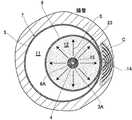
図1および図2は、本発明の第1実施例におけるバルーンカテーテルを示している。これらの各図において、1は管腔臓器内に挿入可能な柔軟性に富む筒状のカテーテルシャフトであって、このカテーテルシャフト1は、互いに前後方向にスライド可能な外筒シャフト2と、中筒シャフト3と、内筒シャフト4とにより構成される。外筒シャフト2の先端部2Aと、内筒シャフト4の先端部4A近傍との間には、外部に露出する外表面を有する外バルーン5が設けられ、中筒シャフト3の先端部3Aと、内筒シャフト4の先端部4A近傍との間には、外バルーン5に外表面が囲まれた内バルーン6が設けられる。これら二重の外バルーン5と内バルーン6とにより、カテーテルシャフト1の先端側でバルーン内バルーン構造のバルーン部7が装着される。[First embodiment]
1 and 2 show a balloon catheter in a first embodiment of the present invention. In each of these drawings, 1 is a flexible cylindrical catheter shaft that can be inserted into a hollow organ, and this
外バルーン5の内表面の内バルーン6の外表面との間の内部空間は、低熱伝導性ガス(空気または炭酸ガス)の充填部11として形成される。また、内バルーン6で囲まれた内部空間は、前記充填部11とは隔離した電解質溶液の充填部12として形成される。充填部11に気体を充填投入することにより、外バルーン5は略球形に膨らみ、充填部12に液体を充填投入することにより、内バルーン6が略球形に膨らむ構成となっている。 An internal space between the inner surface of the
外バルーン5の前側の基端側と後側の先端側には、内筒シャフト4を挿通するシャフト接続口5A,5Bがそれぞれ設けられ、内バルーン6の前側の基端側と後側の先端側にも、内筒シャフト4を挿通するシャフト接続口6A,6Bがそれぞれ設けられる。外バルーン5のシャフト接続口5Aは、前記外筒シャフト2の先端部2Aに臨んでおり、内バルーン6のシャフト接続口6Aは、前記中筒シャフト3の先端部3Aに臨んでいる。内筒シャフト4の先端部4Aは、外バルーン5の先端側にあるシャフト接続口5Bと、内バルーン6の先端側にあるシャフト接続口6Bで固定され、これにより外筒シャフト2と中筒シャフト3に対して、内筒シャフト4が軸方向に沿ってスライドできる構成になっている。
本実施例のバルーン部7は、内バルーン6のシャフト接続口6A,6Bを結ぶ直線が、内バルーン6の回転軸となる中心線に一致して設けられ、外バルーン5のシャフト接続口5A,5Bを結ぶ直線が、外バルーン5の回転軸となる中心線より偏移するように設けられている。ここで、内バルーン6のシャフト接続口6A,6Bを結ぶ直線と、外バルーン5のシャフト接続口5A,5Bを結ぶ直線は、何れも内筒シャフト4の軸線に一致するので、内バルーン6の中心に内筒シャフト4が配置される一方で、外バルーン5の中心より一側に偏って、内筒シャフト4が配置されることになる。そして、外バルーン5と内バルーン6を拡張した状態で、管腔内壁に接触するバルーン部7の一側に偏った部分で、何れも拡張した外バルーン5と内バルーン6とを部分的に密着可能にする密着部14が形成される。 In the
バルーン部7の内部において、内バルーン6の中心部には、内バルーン6の内部を加熱する電極としての高周波通電用電極15が、内筒シャフト4にコイル状に巻回されて設けられている。高周波通電用電極15は単極構造であって、カテーテルシャフト1の外部に設けられた図示しない対極板との間で高周波通電を行なうように構成されている。そして、高周波通電することによって、高周波通電用電極15が発熱するようになっている。なお、高周波通電用電極15を双極構造として、両極間にて高周波通電を行なうように構成してもよい。 Inside the
また、バルーン部7の内部において、内筒シャフト4の基端部側には、高周波通電用電極15に接して高周波通電用電極15の温度を検知するための温度センサー16が固定されている。なお、本実施例では図示しないが、当該温度センサー16の他に、バルーン部7の内部温度を検知する別な温度センサーを、内筒シャフト4の先端部4A近傍に固定してもよい。こうした別な温度センサーの詳細については、本願出願人による国際出願公開第2010/070766号を参照されたい。 In addition, a
外筒シャフト2と中筒シャフト3との間には、外バルーン5と内バルーン6との間の充填部11に通じて、この充填部11に低熱伝導性ガスを送る送気路21が形成される。これとは別に、中筒シャフト3と内筒シャフト4との間には、内バルーン6の内部に形成した充填部12に通じて、この充填部に電解質溶液を送ると共に振動波を伝える送液路22が形成される。23は、バルーン部7を標的部位に誘導するためのガイドワイアーであり、このガイドワイアー23は、内筒シャフト4を挿通して設けられている。 Between the
カテーテルシャフト1の外部には、高周波通電用電極15に電力である高周波エネルギーを供給して、内バルーン6を加温する高周波発生器25が設けられている。この高周波発生装置25は、温度センサー16からの検知信号により、高周波通電用電極15ひいては内バルーン6の内部温度を測定し、その温度を表示する温度計26を備えている。高周波発生装置25は、温度計26で測定された温度情報を逐次取り込んで、高周波通電用電極15に供給する高周波電流のエネルギーを決定する構成となっている。また、このような構成を実現するために、高周波通電用電極15と高周波発生装置25は、リード線27により電気的に接続され、温度センサー16と温度計26は、別なリード線28により電気的に接続される。そして、内筒シャフト4の軸方向全長にわたり、リード線27,28は内筒シャフト4に沿って固定されている。 A
その他に、カテーテルシャフト1の外部には、送気路21を介して充填部11に気体を供給するガス注入器としてのシリンジ31と、送液路22を介して充填部12に液体を供給する液体注入器としてのシリンジ32と、送液路22を通じて充填部12に非対称の振動波Wを与えて、内バルーン6の内部に定常的に渦Sを発生させる振動発生器33がそれぞれ設けられている。そして、シリンジ31によって充填部11に供給される気体の圧力を変化させることにより、外バルーン5の直径が変化し、シリンジ32によって充填部12に供給される液体の圧力を変化させることにより、内バルーン6の直径が変化するように構成されている。また、渦Sによって、内バルーン6の内部の液体が振動攪拌されて、内バルーン6の内部の温度が均一に保たれるようになっている。 In addition, a
また35は、管腔内におけるバルーン部7の位置を目視で確認するための内視鏡である。内視鏡35は周知のように、光学レンズを先端に装着した可撓管により構成され、カテーテルシャフト1の外部に設置した表示モニター(図示せず)により、管腔内を目視観察できるようになっている。
なお、本実施例において、内バルーン6の内部を加熱するために、内筒シャフト4の先端部4A近傍に固定された高周波通電用電極15を用いているが、内バルーン6の内部を加熱できれば、特定のものに限定されない。例えば、高周波通電用電極15と高周波発生装置25の代わりに、超音波発熱体と超音波発生装置、レーザー発熱体とレーザー発生装置、ダイオード発熱体とダイオード電源供給装置、ニムロム線発熱体とニクロム線電源供給装置の何れかを用いることができる。 In the present embodiment, in order to heat the inside of the
また、外バルーン5と内バルーン6は、何れも内バルーン6の内部を加熱する際に、熱変形などを起こさずに耐え得る耐熱性レジン(樹脂)で構成される。外バルーン5と内バルーン6の形状は、図示したような短軸と長軸が等しい球形の他に、例えば短軸を回転軸とした扁球や、長軸を回転軸とした長球や、俵型などの各種回転体とすることができるが、どのような形状であっても、管腔内壁に密着した場合に容易に変形する弾性部材で形成される。 The
外バルーン5と内バルーン6の一部は、接着材37により接着される。具体的には、外バルーン5のシャフト接続口5Bと、内バルーン6のシャフト接続口6Bが、内筒シャフト4の先端部4Aと共に接着材37で接着され、この部分から気体や液体が漏れるのを防いでいる。代わりに、外バルーン5と内バルーン6の一部を、溶融により接合させてもよい。こうすれば、わざわざ接着剤37を塗布しなくても、外バルーン5と内バルーン6を部分的に溶融させることで、この部分からの気体や液体の漏れを防止できる。 A part of the
つぎに、本実施例におけるバルーンカテーテルの使用方法について説明する。図1および図2は、直腸癌の治療に適用した例を示している。 Next, a method for using the balloon catheter in the present embodiment will be described. 1 and 2 show examples applied to the treatment of rectal cancer.
はじめに、カテーテル内腔、すなわち充填部11およびこれに連通する送気路21と、充填部12およびこれに連通する送液路22のエアー抜きを行なう。また、外筒シャフト2の先端部2Aおよび中筒シャフト3の先端部3Aと、内筒シャフト4の先端部4Aとの間の距離が最大になるように、外筒シャフト2および中筒シャフト3と、内筒シャフト4とを相互にスライドさせた状態で、バルーン部7を収縮させる。 First, air is vented from the catheter lumen, that is, the filling
そして、直腸造影を行い、直腸の走行と癌病変部Cの位置を把握したら、先端ループ型のガイドワイアー23を直腸内に挿入し、このガイドワイアー23を介して、予め収縮させストレッチされたバルーン部7を、可撓性のカテーテルシャフト1と共に直腸内に挿入する。それと共に、直腸内に挿入された内視鏡35からの画像を、図示しない表示モニターで観察しながら、バルーン部7を腸管内の標的部位まですすめたら、ストレッチを解除してシリンジ31を動作させ、このシリンジ31から送気路21を通じて外バルーン5内の充填部11にエアー(空気)を注入して、外バルーン5を半分ほど拡張する。 Then, after performing rectal angiography and grasping the position of the rectal run and the cancerous lesion C, a tip loop
次に、別なシリンジ32を動作させ、シリンジ32から送液路22を通じて内バルーン6内の充填部12に生理食塩水とイオン系造影剤の混合充填液を注入することで、内バルーン6を十分に拡張する。この状態で、内筒シャフト4の軸線を中心にバルーン部7全体を回転させて、外バルーン5に対して一側に偏った内バルーン6を、癌病変部Cの方向に向かせる。外バルーン5全体が直腸内壁に密着し、充填部11からの加圧力によって、その位置を保持するようになるまで、シリンジ31から充填部11にエアーを更に注入して、外バルーン5を拡張する。また、内バルーン6が外バルーン5を介在して癌病変部Cに強く密着するように、シリンジ32を操作して、内バルーン6内の充填部12への充填液量を調整する。これにより、充填部12からの加圧力によって、外バルーン5と内バルーン6が接触する密着部14に、標的部位となる癌病変部Cが強く密着するようになる。 Next, another
こうして、バルーン部7の位置決めと、充填部11へのエアー注入量および充填部12への液体注入量を調整し終えたら、内バルーン6内の中心温度を温度計26のモニターで見ながら、高周波発生装置25から高周波通電用電極15への高周波通電を開始する。同時に振動発生器33を作動させ、送液路22を通じて振動波Wを送り込み、重力に対して上下方向の渦Sを内バルーン6の内部に発生させて、内バルーン6の内部の液体を撹拌する。 After the positioning of the
高周波発生装置25は、温度センサー16からの検知信号に基づき、温度計26で測定した内バルーン6内の内部温度が、操作部(図示せず)により設定した温度となるようなエネルギーの高周波電流を、リード線27を通じて高周波通電用電極15に供給する。また、このときの高周波通電用電極15への高周波電流の通電時間は、操作部により設定した時間に一致する。こうして、高周波発生装置25により内バルーン6内の中心温度と、高周波通電用電極15の通電時間を調整しながら、バルーン部7の密着部14に接触する癌病変部Cを加圧焼灼する。 The
具体的には、内バルーン6内の中心温度を70度に保ち、術前診断の癌病変部Cの深度に応じた時間で、高周波通電用電極15に対する高周波通電を行なう。通常、癌病変部Cの深度が1mmから2mmであれば、高周波通電用電極15への通電時間を1分から2分とし、癌病変部Cの深度が2.5mmから3mmであれば、高周波通電用電極15への通電時間を3分から4分とする。内バルーン6内の中心温度を70度(この場合、接触温度は60度〜65度)とし、高周波通電用電極15への通電時間を1分から2分にした場合、筋層は深く焼灼されないので広範囲に焼灼しても狭窄や嚥下障害はきたさないが、3分から4分の通電時間では、筋層が深く焼灼されるので、広い範囲を焼灼すると機能障害をきたすので注意を要する。一般に管腔全周の3分の1以内までの焼灼であれば、機能障害はきたさないと言われている。内視鏡的粘膜下切除術は筋層に達する病変には適応されないが、本実施例による上記方法であれば、転移こそなければ、病変が筋層に達していても治療可能である。60度前後の温度では、全層性に凝固壊死となっても解剖学的構造が保たれている限り、焼灼範囲が狭ければ、内膜のすべて筋層の相当な部分が再生する。この方法は、同様に直腸以外の大腸,小腸や食道の病変に対しても適応できる。 Specifically, the central temperature in the
[第2実施例]
図3は、本発明の第2実施例におけるバルーンカテーテルを示している。本実施例では、内バルーン6のシャフト接続口6A,6Bを結ぶ直線が、略球形に膨らむ内バルーン6の中心線に一致しているだけでなく、外バルーン5のシャフト接続口5A,5Bを結ぶ直線も、略瓢箪型若しくは略俵型に膨らむ外バルーン5の中心線に一致して設けられている。そして、外バルーン5と内バルーン6を拡張した状態で、管腔内壁に接触するバルーン部7の放射方向の周回部分で、外バルーン5と内バルーン6とを部分的に密着可能にする密着部14が形成される。[Second Embodiment]
FIG. 3 shows a balloon catheter in the second embodiment of the present invention. In the present embodiment, the straight line connecting the
外バルーン5と内バルーン6は、本実施例のように異なる形状であってもよく、また外バルーン5と内バルーン6を拡張した状態で、管腔内壁に外バルーン5が押し付けられたときに、その管腔内壁に接触するバルーン部7の放射方向の周回部分で、管腔内壁からの押圧力で外バルーン5が弾性変形することにより、密着部14が形成される構成であってもよい。それ以外のバルーンカテーテルとしての構成は、第1実施例と共通している。 The
つぎに、本実施例におけるバルーンカテーテルの使用方法について説明する。図3は、肺静脈アイソレーションに適用した例を示している。 Next, a method for using the balloon catheter in the present embodiment will be described. FIG. 3 shows an example applied to pulmonary vein isolation.
心房細動治療には肺静脈アイソレーションが有効であるが、肺静脈内をバルーンカテーテルで強く焼灼すると、肺静脈狭窄の合併症をおこす。そこで、図3に示すようなバルーン内バルーン構造のバルーン部7を用いる。 Pulmonary vein isolation is effective for treatment of atrial fibrillation, but if cauterization of the pulmonary vein with a balloon catheter is severe, complications of pulmonary vein stenosis occur. Therefore, a
ここでも先ず、第1実施例と同様にエアー抜きとバルーン部7の収縮を行なった後、外筒シャフト2の外周に設けられたガイドシース(図示せず)と、ガイドワイアー23を用いて、カテーテルシャフト1と共にバルーン部7を大腿静脈より肺静脈内に挿入し、シリンジ31から送気路21を通じて外バルーン5内の充填部11に炭酸ガスを注入して、外バルーン5を炭酸ガスで拡張する。次に、シリンジ32から送液路22を通じて内バルーン6内の充填部12に電解質溶液を注入することで、内バルーン6を電解質溶液で拡張し、外バルーン5との密着部14で肺静脈口周囲部Pに押し付ける。 Also here, first, after performing air venting and contraction of the
高周波発生装置25から高周波通電用電極15への高周波通電により、外バルーン5を介して内バルーン6と接触する肺静脈口周囲Pが焼灼されるが、肺静脈内は外バルーン5内の充填部11に充填された炭酸ガスにより、内バルーン6内からの熱伝導がブロックされて焼灼されず、結果的に肺静脈狭窄を起こさずに肺静脈の電気的隔離を達成できる。また、内バルーン6内の熱エネルギーも、外バルーン5近位の炭酸ガスでブロックされて左心房内血流によって奪われないため、肺静脈口周囲部Pに対する効率のよい焼灼が可能となる。 By high-frequency energization from the high-
[第3実施例]
図4は、本発明の第3実施例におけるバルーンカテーテルを示している。本実施例におけるバルーン部7は、第1実施例と同様に、内バルーン6のシャフト接続口6A,6Bを結ぶ直線が、内バルーン6の中心線に一致して設けられ、外バルーン5のシャフト接続口5A,5Bを結ぶ直線が、外バルーン5の中心線より偏移して設けられている。但し、第1実施例では外バルーン5が内バルーン6と同じく球形であったのに対し、本実施例では内バルーン6が球形であるものの、外バルーン5は扁球状に形成されている。その他の構成は、第1実施例と共通している。[Third embodiment]
FIG. 4 shows a balloon catheter in the third embodiment of the present invention. As in the first embodiment, the
つぎに、本実施例におけるバルーンカテーテルの使用方法について説明する。図4は、前立腺中葉肥大の治療に適用した例を示している。 Next, a method for using the balloon catheter in the present embodiment will be described. FIG. 4 shows an example applied to the treatment of prostatic middle lobe hypertrophy.
これまでのマイクロ波やラジオ波を用いた前立腺肥大治療用デバイスでは、前立腺側葉の焼灼はできても前立腺中葉の焼灼はできなかった。そこで、図4に示すようなバルーン内バルーン構造のバルーン部7を用いる。 Conventional devices for treating benign prostatic hypertrophy using microwaves and radio waves have been able to cauterize the side lobe of the prostate, but not the midlobe of the prostate. Therefore, a
先ず、第1実施例と同様にエアー抜きとバルーン部7の収縮を行なった後、先端ループ型のガイドワイアー23を尿道内に挿入し、このガイドワイアー23を介して、予め収縮させたバルーン部7を、カテーテルシャフト1と共に尿道内に挿入する。バルーン部7を膀胱内にまですすめたら、シリンジ31から送気路21を通じて外バルーン5内の充填部11にエアー(空気)を注入して、外バルーン5を拡張し、シリンジ32から送液路22を通じて内バルーン6内の充填部12に充填剤を注入して、内バルーン6を拡張する。そして、高周波発生装置25から高周波通電用電極15に高周波電流を供給することにより、外バルーン5で膀胱壁を保護しながら、内バルーン6で前立腺中葉の肥大部Eを選択的に焼灼することが可能となる。また、尿道内に本バルーンカテーテルを挿入し、バルーン部7を尿道内に留置した状態で加圧加温すると、前立腺側葉も片方ずつ焼灼可能であるので、無駄な焼灼は控えることができる。 First, after air bleeding and deflation of the
[第4実施例]
図5は、本発明の第4実施例におけるバルーンカテーテルを示している。本実施例におけるバルーン部7は、第1実施例と同様に、内バルーン6のシャフト接続口6A,6Bを結ぶ直線が、内バルーン6の中心線と一致して設けられ、外バルーン5のシャフト接続口5A,5Bを結ぶ直線が、外バルーン5の中心線より偏移するように設けられている。但し、外バルーン5と内バルーン6の形状は、何れも長球形である。その他の構成は、第1実施例と共通している。[Fourth embodiment]
FIG. 5 shows a balloon catheter according to a fourth embodiment of the present invention. As in the first embodiment, the
つぎに、本実施例におけるバルーンカテーテルの使用方法について説明する。図5は、辺在性アテロームプラークの治療に適用した例を示している。 Next, a method for using the balloon catheter in the present embodiment will be described. FIG. 5 shows an example applied to the treatment of distant atheroma plaques.
アテロームプラークが辺在性に存在する場合、図5に示すようなバルーン内バルーン構造のバルーン部7を使用する。これは先ず、第1実施例と同様にエアー抜きとバルーン部7の収縮を行なった後、先端ループ型のガイドワイアー23を血管内に挿入し、このガイドワイアー23を介して、予め収縮させたバルーン部7を、カテーテルシャフト1と共に血管内に挿入する。バルーン部7を標的組織となるアテロームプラークPの近傍にまですすめたら、シリンジ31から送気路21を通じて外バルーン5内の充填部11に炭酸ガスを注入して、外バルーン5を拡張し、シリンジ32から送液路22を通じて内バルーン6内の充填部12に充填剤を注入して、内バルーン6を拡張する。 When atheroma plaques are present in the vicinity, a
高周波発生装置25から高周波通電用電極15への高周波通電により、外バルーン5を介して内バルーン6と接触するアテロームプラークPが焼灼されるが、正常な血管壁は焼灼されず、バルーン部7の密着部14に接するアテロームプラークPのみに温熱治療を加えることができる。アテロ―ムキャップの破裂はマクロファージのだす溶解酵素によると考えられているので、マクロファージを43度(摂氏)の温熱治療にて死滅させると、アテロームプラークPは安定化する。バルーン部7からの高周波加温により、血管マトリックス主成分のコラーゲン線維を軟化させながら、同時にバルーン部7でアテロームプラークPを加圧すると、比較的低圧にて血管解離なく狭窄部位を拡張することもできる。 By high-frequency energization from the high-
(本発明による効果)
これまでの高周波加温バルーンカテーテルでは、バルーン部を標的組織に選択的に密着させることが難しく、バルーン部との接触箇所を無差別に焼灼し、正常組織にも傷を付けた。これに対して、本発明で提案する高周波バルーン内バルーンアブレーションカテーテルを用いると、拡張した外バルーン5は管腔臓器内での位置を保持すると共に内バルーン6との熱伝導を遮断する一方で、内バルーン6は外バルーン5を介して選択的に標的組織(患部)に密着し、内バルーン6の熱エネルギーは外バルーン5との密着部14を介して伝導し、標的組織だけを選択的に焼灼する効果が得られる。(Effects of the present invention)
In conventional high-frequency warming balloon catheters, it is difficult to selectively bring the balloon portion into close contact with the target tissue, and the contact portion with the balloon portion is indiscriminately cauterized, and the normal tissue is also damaged. In contrast, when the high-frequency balloon intra-balloon ablation catheter proposed in the present invention is used, the expanded
また、内バルーン6と外バルーン5は共に標的組織を加圧しながら焼灼するので、血流の豊富な癌組織(例えば、第1実施例の癌病変部C)などであっても、血流を遮断して其のクーリング効果を減じつつ加温するので、充分な焼灼効果が得られる。さらに、正常組織は低熱伝導性ガスで満たされた外バルーン5により熱焼灼から保護されているので、合併症(Collateral Damage:コラテラルダメージ)が発生しない。 Further, since both the
このように、本発明は従来の高周波バルーンアブレーションカテーテルが単一バルーンであったのに対して、バルーン内バルーン構造のバルーン部7を採用している。高周波加温バルーンは内バルーン6として、低熱電導性ガスを充填した外バルーン5の内部に配置され、内バルーン6が外バルーン5を介して標的組織が密着するとき、密着面での熱伝導により標的組織を焼灼するものである。これにより正常組織を傷つけず、選択的に標的組織だけを治療することができるようになる。 As described above, the present invention employs the
以上のように、本発明のバルーンカテーテルは、上記第1実施例〜第4実施例に共通して、互いにスライド可能な外筒シャフト2,中筒シャフト3および内筒シャフト4により構成されるカテーテルシャフト1と、外筒シャフト2の先端部2Aと内筒シャフト4の先端部4Aとの間に設置される拡張可能な外バルーン5と、中筒シャフト3の先端部3Aと内筒シャフト4の先端部4Aとの間に設置され、外バルーン5の内部に収容される拡張可能な内バルーン6と、内バルーン6の内部に設置される高周波通電用電極15および温度センサー16と、中筒シャフト3と内筒シャフト4との間に形成され、内バルーン6の内部に通じる送液路22と、外筒シャフト2と中筒シャフト3との間に形成され、外バルーン5と内バルーン6との間に通じる送気路21と、温度センサー16のリード線28を介して内バルーン6の内部温度を測定しながら、電極に電力を供給する高周波発生器としての高周波発生装置25と、送液路22を介して内バルーン6の内部に充填液を送るシリンジ32と、送液路22を介して内バルーン6の内部に振動波を伝える振動発生器33と、送気路21を介して外バルーン5と内バルーン6との間にガスを送るシリンジ31とを備え、拡張した内バルーン6が拡張した外バルーン5と部分的に密着可能な密着部14を、外バルーン5と内バルーン6からなるバルーン部7に形成している。 As described above, the balloon catheter of the present invention is a catheter constituted by the
この場合、低熱伝導性の気体で満たされる外バルーン5と、外バルーン5の内側にあって、高周波通電用電極15に電力を供給することで、その内部に満たされた充填液が高周波加温される内バルーン6とにより、拡張した外バルーン5は管腔臓器内での位置を保持すると共に内バルーン6の熱伝導を遮断し、内バルーン6の熱エネルギーは外バルーン5との密着部14を介して標的組織を選択的に焼灼する。これにより、非標的組織への熱伝導を確実に遮断して、標的組織のみを選択して効果的に焼灼することが可能になる。 In this case, by supplying power to the
また、上記第1実施例,第3実施例および第4実施例において、内バルーン6の先端側の内筒シャフト接続口に相当するシャフト接続口6Bと、基端側の中筒シャフト接続口に相当するシャフト接続口6Aは、これらのシャフト接続口6A,6Bを結ぶ直線が、内バルーン6の回転軸となる中心線に一致して設けられるが、外バルーン5の先端側の内筒シャフト接続口に相当するシャフト接続口5Bと、基端側の外筒シャフト接続口に相当するシャフト接続口5Aは、これらのシャフト接続口5A,5Bを結ぶ直線が、外バルーン5の回転軸となる中心線より一側に偏移して設けられており、その偏移した一側に前記密着部14を形成している。 In the first embodiment, the third embodiment, and the fourth embodiment, the
このように、内筒シャフト4が挿通する外バルーン5のシャフト接続口5A,5Bを結ぶ直線を、外バルーン5の中心線より一側にずらすことで、その一側に標的組織に対向する部分的な密着部14を容易に形成できると共に、外バルーン5の中心線に対して、密着部14と反対側にある外バルーン5と内バルーン6との間に、内バルーン6の熱伝導を遮断する空間(充填部11)を広く確保できる。 Thus, by shifting the straight line connecting the
代わりに、別な第2実施例では、内バルーン6のシャフト接続口6A,6Bと、外バルーン5のシャフト接続口5A,5Bは、いずれもシャフト接続口5A,5Bとシャフト接続口6A,6Bを結ぶ直線が外バルーン5と内バルーン6の中心線に一致するように設けられ、内バルーン6と外バルーン5の形状と、カテーテルシャフト1上の外バルーン5の設置部位を変えることで、密着部14が形成される
この場合、内筒シャフト4に対して外バルーン5と内バルーン6を同一の中心線上に配置できると共に、内バルーン6と外バルーン5の形状とカテーテルシャフト1上の設置部位を変えることで、密着部14を容易に形成できる。。Instead, in another second embodiment, the
また第2実施例では、外バルーン5と内バルーン6が異なる形状を有し、この形状の違いにより密着部14を形成してもよい。 In the second embodiment, the
この場合、外バルーン5と内バルーン6の形状の違いを利用して、任意の位置に密着部14を形成することができる。また、この密着部14以外の位置で、外バルーン5と内バルーン6との間に、内バルーン6の熱伝導を遮断する空間(充填部11)を広く確保できる。 In this case, the
さらに第2実施例では、密着部14よりも先端側に、外バルーン5と内バルーン6との間のガス空間である充填部11が閉塞して形成される。このようにすると、管腔臓器内で血流のような流れを先端側から受けても、内バルーン6内の熱エネルギーは密着部14よりも先端側にあるガス空間でブロックされて奪われないため、標的組織に対する効率のよい焼灼が可能となる。 Furthermore, in the second embodiment, the filling
また、上記第1実施例〜第4実施例に共通して、外バルーン5および内バルーン6は、何れも弾性に富む耐熱性レジンで構成され、回転体形状に形成される。 Further, in common with the first to fourth embodiments, the
こうすると、外バルーン5と内バルーン6を拡張させたときに、管腔臓器からの押圧力で外バルーン5や内バルーン6が容易に弾性変形する。そのため、拡張した外バルーン5を所定の位置に保持することができ、また標的組織を密着部14に確実に押し当てることができる。また、外バルーン5と内バルーン6を耐熱性レジンとすることにより、内バルーン6からの熱エネルギーで、外バルーン5や内バルーン6が熱変形するなどの不具合を回避できる。さらに、外バルーン5と内バルーン6を様々な回転体形状とすることができる。 Thus, when the
また、上記第1実施例や第3実施例では、外バルーン5と内バルーン6の一部を接着剤37で接着する構成を採用している。 In the first and third embodiments, a configuration in which a part of the
このようにすると、外バルーン5と内バルーン6の接着した部分から、ガスや充填液が漏れるのを防止できる。 If it does in this way, it can prevent that gas and a filling liquid leak from the part which
代わりに、外バルーン5と内バルーン6の一部を溶融により接合する構成としてもよい。 Instead, a part of the
外バルーン5と内バルーン6を部分的に溶融させることで、この部分からのガスや充填液の漏れを防止できる。 By partially melting the
なお本発明は、本実施例に限定されるものではなく、本発明の要旨の範囲内で種々の変形実施が可能である。例えば、外バルーン5や内バルーン6の形状は、上記各実施例で示したものに限定されず、治療部位に応じた種々の形状に形成してもよい。 The present invention is not limited to the present embodiment, and various modifications can be made within the scope of the gist of the present invention. For example, the shapes of the
1 カテーテルシャフト
2 外筒シャフト
3 中筒シャフト
4 内筒シャフト
5 外バルーン
5A シャフト接続口(外筒シャフト接続口)
5B シャフト接続口(内筒シャフト接続口)
6 内バルーン
6A シャフト接続口(中筒シャフト接続口)
6B シャフト接続口(内筒シャフト接続口)
15 高周波通電用電極(電極)
16 温度センサー
21 送気路
22 送液路
25 高周波発生装置(高周波発生器)
28 リード線
31 シリンジ(ガス注入器)
32 シリンジ(液体注入器)
33 振動発生器
37 接着剤DESCRIPTION OF
5B Shaft connection port (Inner cylinder shaft connection port)
6
6B Shaft connection port (Inner cylinder shaft connection port)
15 Electrode for high-frequency energization (electrode)
16
28
32 Syringe (liquid injector)
33
Claims (6)
Translated fromJapanese前記外筒シャフトの先端部と前記内筒シャフトの先端部との間に設置される外バルーンと、
前記中筒シャフトの先端部と前記内筒シャフトの先端部との間に設置され、前記外バルーンの内部に収容される内バルーンと、
前記内バルーンの内部に設置される電極および温度センサーと、
前記中筒シャフトと前記内筒シャフトとの間に形成され、前記内バルーンの内部に通じる送液路と、
前記外筒シャフトと前記中筒シャフトとの間に形成され、前記外バルーンと前記内バルーンとの間に通じる送気路と、
前記温度センサーのリード線を介して前記内バルーンの内部温度を測定しながら、前記電極に電力を供給する高周波発生器と、
前記送液路を介して前記内バルーンの内部に充填液を送る液体注入器と、
前記送液路を介して前記内バルーンの内部に振動波を伝える振動発生器と、
前記送気路を介して前記外バルーンと前記内バルーンとの間にガスを送るガス注入器とを備え、
拡張した前記内バルーンが拡張した前記外バルーンと部分的に密着可能な密着部を形成したことを特徴とするバルーンカテーテル。A catheter shaft constituted by an outer cylinder shaft, an intermediate cylinder shaft and an inner cylinder shaft which are slidable from each other;
An outer balloon installed between the tip of the outer cylinder shaft and the tip of the inner cylinder shaft;
An inner balloon installed between the distal end portion of the middle cylindrical shaft and the distal end portion of the inner cylindrical shaft, and housed inside the outer balloon;
An electrode and a temperature sensor installed inside the inner balloon;
A liquid feed path formed between the inner cylinder shaft and the inner cylinder shaft and leading to the inside of the inner balloon;
An air supply path formed between the outer cylinder shaft and the middle cylinder shaft and communicating between the outer balloon and the inner balloon;
A high-frequency generator for supplying power to the electrode while measuring the internal temperature of the inner balloon via the lead wire of the temperature sensor;
A liquid injector for sending a filling liquid into the inner balloon via the liquid delivery path;
A vibration generator for transmitting a vibration wave to the inside of the inner balloon via the liquid feeding path;
A gas injector for sending gas between the outer balloon and the inner balloon via the air supply path;
A balloon catheter, wherein the expanded inner balloon is formed with a close contact portion capable of partially contacting with the expanded outer balloon.
Priority Applications (3)
| Application Number | Priority Date | Filing Date | Title |
|---|---|---|---|
| JP2011283655AJP2013132364A (en) | 2011-12-26 | 2011-12-26 | Balloon catheter |
| EP12172146.8AEP2609884A1 (en) | 2011-12-26 | 2012-06-15 | Balloon catheter |
| US13/530,804US20130165914A1 (en) | 2011-12-26 | 2012-06-22 | Balloon catheter |
Applications Claiming Priority (1)
| Application Number | Priority Date | Filing Date | Title |
|---|---|---|---|
| JP2011283655AJP2013132364A (en) | 2011-12-26 | 2011-12-26 | Balloon catheter |
Publications (1)
| Publication Number | Publication Date |
|---|---|
| JP2013132364Atrue JP2013132364A (en) | 2013-07-08 |
Family
ID=46395469
Family Applications (1)
| Application Number | Title | Priority Date | Filing Date |
|---|---|---|---|
| JP2011283655APendingJP2013132364A (en) | 2011-12-26 | 2011-12-26 | Balloon catheter |
Country Status (3)
| Country | Link |
|---|---|
| US (1) | US20130165914A1 (en) |
| EP (1) | EP2609884A1 (en) |
| JP (1) | JP2013132364A (en) |
Cited By (4)
| Publication number | Priority date | Publication date | Assignee | Title |
|---|---|---|---|---|
| WO2015095629A1 (en)* | 2013-12-20 | 2015-06-25 | The Johns Hopkins University | Method and apparatus for selective treatiment inside a body lumen |
| JP2017192740A (en)* | 2013-11-26 | 2017-10-26 | パーシステント エーエフアイビー ソリューションズ, インク.Persistent Afib Solutions, Inc. | Action / reaction superposition double chamber, wide area tissue resection device |
| JP2020533144A (en)* | 2017-09-12 | 2020-11-19 | 康▲豊▼生物科技(上海)有限公司 | Cryoablation catheters and systems |
| WO2021201076A1 (en)* | 2020-03-31 | 2021-10-07 | 東レ株式会社 | Balloon-equipped catheter |
Families Citing this family (13)
| Publication number | Priority date | Publication date | Assignee | Title |
|---|---|---|---|---|
| US9700365B2 (en) | 2008-10-06 | 2017-07-11 | Santa Anna Tech Llc | Method and apparatus for the ablation of gastrointestinal tissue |
| US10064697B2 (en) | 2008-10-06 | 2018-09-04 | Santa Anna Tech Llc | Vapor based ablation system for treating various indications |
| US10695126B2 (en) | 2008-10-06 | 2020-06-30 | Santa Anna Tech Llc | Catheter with a double balloon structure to generate and apply a heated ablative zone to tissue |
| EP3964151A3 (en) | 2013-01-17 | 2022-03-30 | Virender K. Sharma | Apparatus for tissue ablation |
| US10709490B2 (en)* | 2014-05-07 | 2020-07-14 | Medtronic Ardian Luxembourg S.A.R.L. | Catheter assemblies comprising a direct heating element for renal neuromodulation and associated systems and methods |
| US12364537B2 (en) | 2016-05-02 | 2025-07-22 | Santa Anna Tech Llc | Catheter with a double balloon structure to generate and apply a heated ablative zone to tissue |
| US11331140B2 (en) | 2016-05-19 | 2022-05-17 | Aqua Heart, Inc. | Heated vapor ablation systems and methods for treating cardiac conditions |
| CN108309432B (en)* | 2018-04-13 | 2024-04-09 | 山前(珠海)医疗科技有限公司 | Cryoablation catheter, cryoablation operating device and cryoablation equipment |
| EP3801324B1 (en) | 2018-06-01 | 2025-05-28 | Aqua Medical, Inc. | Vapor generation and delivery systems |
| CN113015495A (en)* | 2018-09-11 | 2021-06-22 | 阿卡赫特有限公司 | Heating steam ablation system and method for treating heart disease |
| US11395697B2 (en)* | 2018-11-14 | 2022-07-26 | Medtronic, Inc. | Devices and methods for preparing a valve for a transcatheter valve replacement procedure |
| CN113318329B (en)* | 2021-07-06 | 2025-09-02 | 上海英诺伟医疗器械股份有限公司 | Double-balloon catheter |
| CN118902599B (en)* | 2024-07-31 | 2025-02-28 | 诺宜思医疗科技(北京)有限公司 | Endoscopic pancreatic radiofrequency ablation catheter |
Citations (2)
| Publication number | Priority date | Publication date | Assignee | Title |
|---|---|---|---|---|
| JP2008167958A (en)* | 2007-01-12 | 2008-07-24 | Nippon Erekuteru:Kk | High frequency heating balloon catheter system |
| US20110190751A1 (en)* | 2010-02-01 | 2011-08-04 | Boston Scientific Scimed, Inc. | Nested balloon cryotherapy |
Family Cites Families (10)
| Publication number | Priority date | Publication date | Assignee | Title |
|---|---|---|---|---|
| US5151100A (en)* | 1988-10-28 | 1992-09-29 | Boston Scientific Corporation | Heating catheters |
| JP3607231B2 (en)* | 2001-09-28 | 2005-01-05 | 有限会社日本エレクテル | High frequency heating balloon catheter |
| US6989009B2 (en)* | 2002-04-19 | 2006-01-24 | Scimed Life Systems, Inc. | Cryo balloon |
| US6929639B2 (en)* | 2002-08-30 | 2005-08-16 | Scimed Life Systems, Inc. | Cryo ablation coil |
| US20050124843A1 (en)* | 2003-12-09 | 2005-06-09 | Washington University | Method and apparatus for delivering targeted therapy to a patient |
| US20070299433A1 (en)* | 2006-06-27 | 2007-12-27 | C2 Therapeutics | Barrett's Esophagus Cryogenic Ablation System |
| US8465481B2 (en)* | 2008-10-20 | 2013-06-18 | Boston Scientific Scimed, Inc. | Providing cryotherapy with a balloon catheter having a non-uniform thermal profile |
| EP2382933B1 (en)* | 2008-12-19 | 2016-11-30 | Japan Electel Inc. | Balloon catheter system |
| US9039687B2 (en)* | 2010-10-28 | 2015-05-26 | Medtronic Ablation Frontiers Llc | Reactance changes to identify and evaluate cryo ablation lesions |
| US20120150107A1 (en)* | 2010-12-14 | 2012-06-14 | Boston Scientific Scimed, Inc. | Balloon catheter shafts and methods of manufacturing |
- 2011
- 2011-12-26JPJP2011283655Apatent/JP2013132364A/enactivePending
- 2012
- 2012-06-15EPEP12172146.8Apatent/EP2609884A1/ennot_activeWithdrawn
- 2012-06-22USUS13/530,804patent/US20130165914A1/ennot_activeAbandoned
Patent Citations (2)
| Publication number | Priority date | Publication date | Assignee | Title |
|---|---|---|---|---|
| JP2008167958A (en)* | 2007-01-12 | 2008-07-24 | Nippon Erekuteru:Kk | High frequency heating balloon catheter system |
| US20110190751A1 (en)* | 2010-02-01 | 2011-08-04 | Boston Scientific Scimed, Inc. | Nested balloon cryotherapy |
Cited By (6)
| Publication number | Priority date | Publication date | Assignee | Title |
|---|---|---|---|---|
| JP2017192740A (en)* | 2013-11-26 | 2017-10-26 | パーシステント エーエフアイビー ソリューションズ, インク.Persistent Afib Solutions, Inc. | Action / reaction superposition double chamber, wide area tissue resection device |
| US10166058B2 (en) | 2013-11-26 | 2019-01-01 | Corfigo, Inc. | Action/counteraction superimposed double chamber broad area tissue ablation device |
| WO2015095629A1 (en)* | 2013-12-20 | 2015-06-25 | The Johns Hopkins University | Method and apparatus for selective treatiment inside a body lumen |
| JP2020533144A (en)* | 2017-09-12 | 2020-11-19 | 康▲豊▼生物科技(上海)有限公司 | Cryoablation catheters and systems |
| JP7211635B2 (en) | 2017-09-12 | 2023-01-24 | 康▲豊▼生物科技(上海)有限公司 | cryoablation catheters and systems |
| WO2021201076A1 (en)* | 2020-03-31 | 2021-10-07 | 東レ株式会社 | Balloon-equipped catheter |
Also Published As
| Publication number | Publication date |
|---|---|
| US20130165914A1 (en) | 2013-06-27 |
| EP2609884A1 (en) | 2013-07-03 |
Similar Documents
| Publication | Publication Date | Title |
|---|---|---|
| JP2013132364A (en) | Balloon catheter | |
| US11179187B2 (en) | Methods for delivering energy into a target tissue of a body | |
| JP4988044B2 (en) | Balloon catheter system | |
| JP4702704B2 (en) | Balloon catheter system | |
| JP3607231B2 (en) | High frequency heating balloon catheter | |
| WO2015049784A1 (en) | Balloon catheter ablation system | |
| US9161801B2 (en) | Medical system and method of use | |
| JP6320978B2 (en) | High frequency balloon catheter system | |
| CA2607476C (en) | Wide area ablation of myocardial tissue | |
| US20070288001A1 (en) | Endoscopically introducible expandable cautery device | |
| CA2779386C (en) | Method and apparatus for treatment of hypertension through percutaneous ultrasound renal denervation | |
| US11284931B2 (en) | Medical systems and methods for ablating and absorbing tissue | |
| US20070287994A1 (en) | Endoscopically Introducible Expandable Bipolar Probe | |
| EP3041425B1 (en) | Radio frequency (rf) balloon catheter having flushing and cooling capability | |
| WO2010134503A1 (en) | Ablation catheter with balloon, and ablation catheter system with balloon | |
| JP2015525607A (en) | Ablation device having an expandable chamber for anchoring the ablation device to tissue | |
| JP2004223080A (en) | High frequency heating balloon catheter | |
| WO2012122157A1 (en) | Radiofrequency ablation catheter device | |
| US20220175438A1 (en) | Medical system and method of use | |
| US20220117645A1 (en) | Medical system and method of use | |
| US20240000493A1 (en) | Medical system and method of use | |
| JP2003210482A (en) | Heating treatment instrument |
Legal Events
| Date | Code | Title | Description |
|---|---|---|---|
| A621 | Written request for application examination | Free format text:JAPANESE INTERMEDIATE CODE: A621 Effective date:20131009 | |
| A977 | Report on retrieval | Free format text:JAPANESE INTERMEDIATE CODE: A971007 Effective date:20140206 | |
| A131 | Notification of reasons for refusal | Free format text:JAPANESE INTERMEDIATE CODE: A131 Effective date:20140318 | |
| A02 | Decision of refusal | Free format text:JAPANESE INTERMEDIATE CODE: A02 Effective date:20140708 |