JP2013132103A - Sheet member, charger, and charging system of portable device - Google Patents
Sheet member, charger, and charging system of portable deviceDownload PDFInfo
- Publication number
- JP2013132103A JP2013132103AJP2011278484AJP2011278484AJP2013132103AJP 2013132103 AJP2013132103 AJP 2013132103AJP 2011278484 AJP2011278484 AJP 2011278484AJP 2011278484 AJP2011278484 AJP 2011278484AJP 2013132103 AJP2013132103 AJP 2013132103A
- Authority
- JP
- Japan
- Prior art keywords
- power transmission
- portable device
- sheet member
- power
- charging
- Prior art date
- Legal status (The legal status is an assumption and is not a legal conclusion. Google has not performed a legal analysis and makes no representation as to the accuracy of the status listed.)
- Pending
Links
- 239000000463materialSubstances0.000claimsabstractdescription10
- 230000005540biological transmissionEffects0.000claimsdescription70
- 238000010168coupling processMethods0.000claimsdescription18
- 230000008878couplingEffects0.000claimsdescription10
- 238000005859coupling reactionMethods0.000claimsdescription10
- 230000005684electric fieldEffects0.000claimsdescription9
- 229920002725thermoplastic elastomerPolymers0.000claimsdescription9
- 230000005484gravityEffects0.000claimsdescription4
- 230000007423decreaseEffects0.000claimsdescription3
- 229920002803thermoplastic polyurethanePolymers0.000claimsdescription3
- 239000004014plasticizerSubstances0.000claimsdescription2
- 229920002050silicone resinPolymers0.000claimsdescription2
- 229920005992thermoplastic resinPolymers0.000claims1
- 230000001939inductive effectEffects0.000abstract1
- 230000002401inhibitory effectEffects0.000abstract1
- 238000004891communicationMethods0.000description14
- 238000000034methodMethods0.000description10
- 229920001971elastomerPolymers0.000description6
- 230000006870functionEffects0.000description4
- 230000000694effectsEffects0.000description3
- 230000005674electromagnetic inductionEffects0.000description3
- 229920001187thermosetting polymerPolymers0.000description3
- 238000010586diagramMethods0.000description2
- 238000005286illuminationMethods0.000description2
- 239000002184metalSubstances0.000description2
- 238000009774resonance methodMethods0.000description2
- 229920000877Melamine resinPolymers0.000description1
- 239000004640Melamine resinSubstances0.000description1
- BZHJMEDXRYGGRV-UHFFFAOYSA-NVinyl chlorideChemical compoundClC=CBZHJMEDXRYGGRV-UHFFFAOYSA-N0.000description1
- 230000002159abnormal effectEffects0.000description1
- 230000032683agingEffects0.000description1
- 230000004397blinkingEffects0.000description1
- 239000003086colorantSubstances0.000description1
- 238000006073displacement reactionMethods0.000description1
- 230000006698inductionEffects0.000description1
- 239000011810insulating materialSubstances0.000description1
- 229920005989resinPolymers0.000description1
- 239000011347resinSubstances0.000description1
- 239000004065semiconductorSubstances0.000description1
- 239000004034viscosity adjusting agentSubstances0.000description1
Images


Classifications
- Y—GENERAL TAGGING OF NEW TECHNOLOGICAL DEVELOPMENTS; GENERAL TAGGING OF CROSS-SECTIONAL TECHNOLOGIES SPANNING OVER SEVERAL SECTIONS OF THE IPC; TECHNICAL SUBJECTS COVERED BY FORMER USPC CROSS-REFERENCE ART COLLECTIONS [XRACs] AND DIGESTS
- Y02—TECHNOLOGIES OR APPLICATIONS FOR MITIGATION OR ADAPTATION AGAINST CLIMATE CHANGE
- Y02B—CLIMATE CHANGE MITIGATION TECHNOLOGIES RELATED TO BUILDINGS, e.g. HOUSING, HOUSE APPLIANCES OR RELATED END-USER APPLICATIONS
- Y02B40/00—Technologies aiming at improving the efficiency of home appliances, e.g. induction cooking or efficient technologies for refrigerators, freezers or dish washers
Landscapes
- Charge And Discharge Circuits For Batteries Or The Like (AREA)
Abstract
Description
Translated fromJapanese本発明は、非接触充電により携帯機器を充電する際に敷くシート部材、シート部材を備えた充電器および携帯機器の充電システムに関する。 The present invention relates to a sheet member spread when charging a portable device by non-contact charging, a charger including the sheet member, and a charging system for the portable device.
充電器と携帯機器との間にケーブルやコネクタなど電気的接続箇所を設けない非接触充電には、磁界結合方式と、電界結合方式とがある。磁界結合方式は、さらに電磁誘導方式と磁界共振方式とに分類される。電磁誘導方式と磁界共振方式では、充電器側のコイルと携帯機器側のコイルを互いに対向配置させて充電器が携帯機器へ送電する点では同じであるが、磁界結合モードが異なる。一方、電界結合方式では、充電器側の電極と携帯機器側の電極との間で容量結合させることによって充電器から携帯機器に送電される。 Non-contact charging in which an electrical connection portion such as a cable or a connector is not provided between the charger and the portable device includes a magnetic field coupling method and an electric field coupling method. The magnetic field coupling method is further classified into an electromagnetic induction method and a magnetic field resonance method. The electromagnetic induction method and the magnetic field resonance method are the same in that the charger-side coil and the portable device-side coil are arranged to face each other and the charger transmits power to the portable device, but the magnetic field coupling modes are different. On the other hand, in the electric field coupling method, power is transmitted from the charger to the portable device by capacitive coupling between the electrode on the charger side and the electrode on the portable device side.
上述した非接触充電では、充電中に携帯機器は充電器に対向配置されている。しかし、携帯機器がバイブレータを備えた携帯電話機の場合、充電中に着信があったときに携帯電話機がバイブレータの振動により移動する場合がある。この場合、携帯電話機が充電器に対向しなくなって、充電器が携帯電話機へ送電できなくなる可能性がある。そこで、充電中の携帯電話機の移動を抑制可能な充電システムが特許文献1に開示されている。特許文献1に開示された充電システムでは、充電器の表面(携帯機器を載せる面)に接続手段としてのゴム面を形成することによって、充電中の携帯電話機の移動を抑制している。 In the non-contact charging described above, the portable device is disposed opposite to the charger during charging. However, when the mobile device is a mobile phone provided with a vibrator, the mobile phone may move due to vibration of the vibrator when an incoming call is received during charging. In this case, the mobile phone may not face the charger, and the charger may not be able to transmit power to the mobile phone. Therefore, Patent Document 1 discloses a charging system capable of suppressing the movement of a mobile phone during charging. In the charging system disclosed in Patent Document 1, the movement of the mobile phone during charging is suppressed by forming a rubber surface as a connecting means on the surface of the charger (the surface on which the portable device is placed).
携帯機器、充電器は、充電に伴う電損、誘導損によって温度が上昇する傾向がある。特許文献1に開示された充電システムにおいて、充電器の表面に形成されたゴム面に熱硬化性ゴムが用いられた場合、熱硬化性ゴムは、携帯機器で発生した熱によって粘度が高くなったり、経年劣化によって硬くなる可能性がある。この場合、充電前に比べむしろ携帯電話機が移動しやすい状態となってしまう。 The temperature of portable devices and chargers tends to increase due to electric loss and induction loss associated with charging. In the charging system disclosed in Patent Document 1, when a thermosetting rubber is used on the rubber surface formed on the surface of the charger, the thermosetting rubber has a high viscosity due to heat generated in the portable device. , May become hard due to aging. In this case, the mobile phone is more likely to move than before charging.
本発明は、充電中の携帯機器の移動を抑制する効果を向上させることが可能なシート部材、充電器、および携帯機器の充電システムを提供することを目的とする。 An object of this invention is to provide the sheet | seat member which can improve the effect which suppresses the movement of the portable device during charge, a charger, and the charging system of a portable device.
上記目的を達成するため、本発明のシート部材は、携帯機器と、前記携帯機器を非接触充電にて充電するための充電器と、の間に敷くシート部材であって、加熱されると粘度が低下する材料である。 In order to achieve the above object, the sheet member of the present invention is a sheet member laid between a portable device and a charger for charging the portable device by non-contact charging, and when heated, the viscosity of the sheet member is increased. Is a material that decreases.
上記目的を達成するため、本発明の充電器は、受電部を備えた携帯機器を非接触充電にて充電するための充電器であって、前記携帯機器が載せられる面に設けられた上記シート部材と、前記シート部材を挟んで前記受電部が対向する位置で電磁結合または電界結合により前記受電部に送電する送電部と、を有する。 In order to achieve the above object, the charger according to the present invention is a charger for charging a portable device including a power receiving unit by non-contact charging, and is provided on the surface on which the portable device is placed. And a power transmission unit configured to transmit power to the power reception unit by electromagnetic coupling or electric field coupling at a position where the power reception unit faces across the sheet member.
上記目的を達成するため、本発明の携帯機器の充電システムは、受電部を備えた携帯機器と、前記携帯機器を非接触充電にて充電するための充電器であって、前記携帯機器が載せられる面に設けられた上記シート部材と、前記シート部材を挟んで前記受電部が対向する位置で電磁結合または電界結合により前記受電部に送電する送電部と、を有する。 In order to achieve the above object, a portable device charging system according to the present invention includes a portable device including a power receiving unit and a charger for charging the portable device by non-contact charging, the portable device being mounted on the portable device. And a power transmission unit that transmits power to the power reception unit by electromagnetic coupling or electric field coupling at a position facing the power reception unit across the sheet member.
本発明によれば、充電中の携帯機器の移動を抑制する効果を向上させることが可能となる。 ADVANTAGE OF THE INVENTION According to this invention, it becomes possible to improve the effect which suppresses the movement of the portable apparatus during charge.
図1は、本発明の充電システムの一実施形態を示す斜視図である。図1に示す充電システム10では、ACアダプタ214が取り付けられた充電器200の上面(表面)にシート部材221が貼り付けられている。シート部材221の上面には、マーク222が形成され、マーク222の上に携帯機器100が配置される。本実施形態では、シート部材221は熱可塑性ゴムとし、携帯機器100は携帯電話機とする。シート部材221は絶縁材料、絶縁加工されたシートであってもよい。携帯機器100および充電器200の電気的構成について説明する。図2は、図1に示す携帯機器100および充電器200の電気的構成を示すブロック図である。 FIG. 1 is a perspective view showing an embodiment of the charging system of the present invention. In the charging system 10 illustrated in FIG. 1, a
まず、携帯機器100の電気的構成について説明する。携帯機器100は、CPU(Central Processing Unit)110を搭載している。CPU110は、バス130を介して図2に示す各部と接続されている。以下、CPU110に接続されている各部について説明する。 First, the electrical configuration of the
ROM(Read Only Memory)111は、CPU110が実行するための通信制御、省電力制御といった各種の制御プログラムや、音声着信時などに鳴らすためのメロディデータを格納している。作業用メモリ112は、RAM(Random Access Memory)であり、CPU110がプログラムを実行する上で一時的に必要とされるデータを格納するように構成されている。不揮発メモリ113は、データの消去、書き込みを自由に行うことができ、電源を切ってもデータの内容が消えない半導体メモリである。不揮発メモリ113には、電話帳データや着信時のイルミネーションなどの各種設定値、ユーザーデータなどが格納されている。無線機送受信部114は、無線によってデータの送受信を行う回路である。LED部115は、複数色の発光が可能なLED(Light Emitting Diode)で構成されている。LED部115は、点滅パターンを変えることにより着信時などのイルミネーション機能の発光部として利用される。バイブレータ116は、着信時に振動することによって音の代わりにユーザーに着信を通知する手段である。キー入力部117は、各種のハードキーの他、タッチパネルなどの入力デバイスによるソフトキーなどにより入力を受け付ける入力回路である。キーバックライト118は、キー入力部117を照光する部品である。表示制御部119は、表示部120の表示を制御する制御回路である。マイク121、スピーカー122、およびレシーバ123は音響部品である。マイク121にて送話者の音声を入力し、レシーバ123より相手話者の音声を出力する。スピーカー122は、上述したメロディデータに示された音などを出力する。電源制御部124は、充電式電池129から携帯機器100の各部に供給される電力を制御する。さらに、電源制御部124は、受電側制御部125を制御して受電コイル128で発生した起電力で充電式電池129を充電する動作を制御する。受電側制御部125は、整流回路126及び通信回路127を制御する。通信回路127は、携帯機器100の受電電圧、充電式電池129の充電状況を示す充電情報を充電器200へ通知する。受電コイル128は、充電器200から受電する機能と、通信用のアンテナ機能とを兼ねている。 A ROM (Read Only Memory) 111 stores various control programs such as communication control and power saving control to be executed by the
次に、充電器200の電気的構成について説明する。充電器200は、送電側制御部210と、電力伝送回路211と、通信回路212と、送電コイル213と、を有する。送電側制御部210は、電力伝送回路211および通信回路212を制御する。通信回路212は、携帯機器100から送信された各種情報を受信して送電側制御部210に提供する。電力伝送回路211は、送電側制御部210の制御に従って送電コイル213へ通電したり、通電を中断したりする。 Next, the electrical configuration of the
次に、本実施形態の充電システムの充電動作について説明する。図3は、図1に示す充電システムの充電動作の手順を示すフローチャートである。 Next, the charging operation of the charging system of this embodiment will be described. FIG. 3 is a flowchart showing the procedure of the charging operation of the charging system shown in FIG.
まず、充電器200の送電側制御部210が、充電対象物であるか否か判断する(ステップS1)。具体的には、送電側制御部210は、電力伝送回路211に送電コイル213へ通電させ、送電コイル213のインピーダンスの変化量を検知する。本実施形態では、携帯機器100が絶縁シート部材221のマーク222に配置されたときに受電コイル128が絶縁シート部材221を挟んで送電コイル213に対向配置される。これにより、送電側制御部210に検知されたインピーダンスの変化量が予め設定された許容範囲内となる。この場合、送電側制御部210は、電力伝送回路211に送電コイル213への送電を開始する。すると、電磁誘導により受電コイル128で起電力が発生し、充電式電池129の充電が開始する(ステップS2)。 First, the power transmission
ステップS1において、インピーダンスの変化量が許容範囲外である場合、送電側制御部210は、電力伝送回路211に送電コイル213への送電を中止させる(ステップS3)。ステップS1からステップS3の動作により、充電器200自身が、シート部材221の上面に載せられた物体が充電対象物なのか金属異物(例えば、鍵)なのか判断し、充電対象物でないと判断した場合には充電を開始しないようにできる。 In step S1, when the amount of change in impedance is outside the allowable range, the power transmission
充電開始後、送電側制御部210は、引き続き送電コイル213のインピーダンスの変化量を検知し、検知したインピーダンスの変化量が許容範囲内であるか否か判断している(ステップS4)。インピーダンスの変化量が許容範囲外になると、送電側制御部210は、電力伝送回路211に送電コイル213への送電を中断させる(ステップS5)。インピーダンスの変化量が許容範囲内である場合には、送電側制御部210は、電力伝送回路211に送電コイル213への送電を継続させる(ステップS6)。 After the start of charging, the power transmission
ステップS6の後、送電側制御部210は、携帯機器100の充電が完了したか否か判断する(ステップS7)。ステップS7の具体的な内容について説明する。携帯機器100では、電源制御部124が充電式電池129の充電状況を示す充電情報を受電側制御部125に定期的に通知する。受電側制御部125は、通知された充電情報を通信回路127に受電コイル128から充電器200に無線送信させる。送信された充電情報は、充電器200の送電コイル213を介して通信回路212に受信される。通信回路212は、受信した充電情報を送電側制御部210に出力する。送電側制御部210は、入力された充電情報に示された充電状況に基づいて携帯機器100の充電が完了したか否か判断する。 After step S6, the power transmission
携帯機器100の充電が完了すると、送電側制御部210は電力伝送回路211に送電コイル213への送電を停止させる(ステップS8)。これにより、充電動作が完了する。 When charging of the
本実施形態では、携帯機器100の充電が進むにつれて携帯機器100、充電器200の温度が上昇すると、シート部材221が加熱される。本実施形態ではシート部材221は熱可塑性ゴムなので、加熱されたシート部材221は粘度が低くなり柔らかくなる。その結果、シート部材221と携帯機器100の密着性が充電前に比べて増す。したがって、充電中の携帯機器100の移動の抑制効果が向上する。 In this embodiment, when the temperature of the
本実施形態によれば、充電中にバイブレータ116が振動しても携帯機器100がマーク222の外側へ移動する可能性は極めて低くなる。仮に、携帯機器100がマーク222の外側へ移動したとしても、送電側制御部210が、送電コイル213のインピーダンスの変化量が許容範囲外になったことを検知して送電コイル213への通電を中断させる。したがって、充電の途中で受電コイル128が送電コイル213に対向配置されなくなるという異常事態が発生してもフェイルセーフが機能する。 According to the present embodiment, even if the
本実施形態の充電システム10では、シート部材221に熱可塑性ゴムを用いる構成であったが、本発明は熱可塑性ゴムに限定されない。シート部材221は、熱可塑性ゴムの他に熱可塑性エラストマーとしての熱可塑性ポリウレタン樹脂、一般には熱硬化しにくい組成のシリコーン樹脂、粘度調整剤としての可塑剤が添加されたゴム、樹脂(例えば塩化ビニルのような熱可塑性樹脂)といった加熱されると粘度が低下する材料であればよい。 In the charging system 10 of the present embodiment, the thermoplastic rubber is used for the
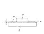
また本発明では、図4に示すように、シート部材221は、携帯機器100が配置されたときに携帯機器100の重量によって重力方向に沈み込むように変形することが望ましい。このようにシート部材221が変形することによって、携帯機器100の周囲を囲む段差がシート部材221に形成される。この段差によって、携帯機器100の移動をさらに抑制することが可能となる。この段差の高さを十分に確保するため、シート部材221の厚さtは、携帯機器100の重量により重力方向に沈み込む深さΔtよりも十分厚いことが望ましい。また充電時の熱と、携帯機器100の質量、充電器200との接触面形状、接触面積とを考慮してシート部材221の厚さtや、粘度を設定すればよい。シート部材221の厚さtや、携帯機器100の沈み込み量が充分に大きくなるように構成すれば充電器200が傾いた状態、斜面に設置された場合にでも横滑りを防ぐこともできる。 In the present invention, as shown in FIG. 4, it is desirable that the
本発明では、シート部材211は熱可塑性ゴムや、前述の材料に限定されない。ゴムのような弾性体だけでなく、加わる力に応じて変形し、力が解放されれば自然と元の形状へと復元するような粘弾性体、例えば熱硬化性ウレタン樹脂やメラミン樹脂のスポンジ状部材であったりしてもよい。熱に応じて粘度が低くなる材料である必要もない。すなわち、本発明のシート部材は、携帯機器と、前記携帯機器を非接触充電にて充電するための充電器と、の間に敷くシート部材であって、前記携帯機器が配置されたときに前記携帯機器の重量によって重力方向に沈み込むように変形する材料であってもよい。 In the present invention, the
シート部材221が携帯機器100の重量に応じて変形すると、受電コイル128と送電コイル213との間の距離も変化する。そのため、携帯機器100を配置した場合と、重量が携帯機器100と異なる他の充電非対象の携帯機器、金属異物を配置した場合では、送電コイル213のインピーダンスの変化量が異なるため誤って送電されることを防ぐことも期待できる。しかしながら、本実施形態のように、送電コイル213のインピーダンスの変化量に基づいて充電対象物か否か判断する場合、携帯機器の重量の違いを考慮できないため判断を誤る可能性がある。そこで、本発明では、充電器200が携帯機器の識別子に基づいて充電対象物か否か判断することとしてもよい。具体的には、ステップS1において、通信回路127が、受電側制御部125の制御に基づいて、ROM11に予め格納されている携帯機器100の識別子を充電器200へ送信する。充電器200では、送電側制御部210が、識別子毎に予め対応付けられている許容範囲に基づいて充電対象物か否か判断する。これにより、携帯機器の重量に関わらず充電対象物か否か正しく判断することが可能となる。 When the
本実施形態では、受電コイル128を受電部とし、送電コイル213を送電部とする磁界結合方式を例に説明したが、電界結合方式でも同様に行うことが可能である。電界結合方式の場合、携帯機器100には受電コイル128の代わりに受電電極が受電部として設けられ、充電器200には送電コイル213の代わりに送電電極が送電部として設けられる。 In the present embodiment, the magnetic field coupling method using the
本実施形態では、シート部材221の上面にマーク222を形成したが、ムービングコイル方式と呼ばれる、携帯機器100の受電コイル128の位置に合わせて充電器200側の送電コイル213が移動する方式や、電界結合方式のように位置ずれに対する充電効率が比較的落ちない方式ではマークは不要である。 In the present embodiment, the
本実施形態では、インピーダンス値を測定する方法や、送電コイル、受電コイル間で通信する方法にて充電制御する例で説明したが、別の方法や、別の通信手段を用いて行ってもよいので、本充電制御に限定されない。充電時に発熱するような非接触充電であればよい。 In the present embodiment, the charging control is described by the method of measuring the impedance value and the method of communicating between the power transmission coil and the power receiving coil, but may be performed using another method or another communication means. Therefore, it is not limited to this charge control. Any non-contact charging that generates heat during charging may be used.
10 充電システム
100 携帯機器
110 CPU
111 ROM
112 作業用メモリ
113 不揮発メモリ
114 無線機送受信部
115 LED部
116 バイブレータ
117 キー入力部
118 キーバックライト
119 表示制御部
120 表示部
121 マイク
122 スピーカー
123 レシーバ
124 電源制御部
125 受電側制御部
126 整流回路
127、212 通信回路
128 受電コイル
129 充電式電池
130 バス
200 充電器
210 送電側制御部
211 電力伝送回路
212 通信回路
213 送電コイル
214 ACアダプタ
221 シート部材
222 マーク10
111 ROM
112
Claims (9)
Translated fromJapanese前記携帯機器が載せられる面に設けられた、請求項1から4のいずれか1項に記載のシート部材と、
前記シート部材を挟んで前記受電部が対向する位置で電磁結合または電界結合により前記受電部に送電する送電部と、を有する充電器。A charger for charging a portable device including a power receiving unit by non-contact charging,
The sheet member according to any one of claims 1 to 4, provided on a surface on which the portable device is placed,
And a power transmission unit configured to transmit power to the power reception unit by electromagnetic coupling or electric field coupling at a position facing the power reception unit across the sheet member.
前記送電コイルに送電する電力伝送回路と、
前記送電コイルのインピーダンスの変化量を検知し、検知した変化量が予め設定された許容範囲内の場合に前記電力伝送回路に前記送電コイルへ送電させる送電側制御部と、をさらに有する、請求項5に記載の充電器。The power reception unit is a power reception coil, and the power transmission unit is a power transmission coil;
A power transmission circuit for transmitting power to the power transmission coil;
A power transmission side control unit that detects a change amount of impedance of the power transmission coil and causes the power transmission circuit to transmit power to the power transmission coil when the detected variation amount is within a preset allowable range. 5. The charger according to 5.
前記携帯機器を非接触充電にて充電するための充電器であって、前記携帯機器が載せられる面に設けられた、請求項1から4のいずれか1項に記載のシート部材と、前記シート部材を挟んで前記受電部が対向する位置で電磁結合または電界結合により前記受電部に送電する送電部と、を有する充電器と、
を有する携帯機器の充電システム。A portable device equipped with a power receiving unit;
The sheet member according to any one of claims 1 to 4, wherein the sheet member is a charger for charging the portable device by non-contact charging, and is provided on a surface on which the portable device is placed. A power transmission unit that transmits power to the power reception unit by electromagnetic coupling or electric field coupling at a position where the power reception unit faces across a member;
A charging system for a portable device.
Priority Applications (1)
| Application Number | Priority Date | Filing Date | Title |
|---|---|---|---|
| JP2011278484AJP2013132103A (en) | 2011-12-20 | 2011-12-20 | Sheet member, charger, and charging system of portable device |
Applications Claiming Priority (1)
| Application Number | Priority Date | Filing Date | Title |
|---|---|---|---|
| JP2011278484AJP2013132103A (en) | 2011-12-20 | 2011-12-20 | Sheet member, charger, and charging system of portable device |
Publications (1)
| Publication Number | Publication Date |
|---|---|
| JP2013132103Atrue JP2013132103A (en) | 2013-07-04 |
Family
ID=48909277
Family Applications (1)
| Application Number | Title | Priority Date | Filing Date |
|---|---|---|---|
| JP2011278484APendingJP2013132103A (en) | 2011-12-20 | 2011-12-20 | Sheet member, charger, and charging system of portable device |
Country Status (1)
| Country | Link |
|---|---|
| JP (1) | JP2013132103A (en) |
Cited By (4)
| Publication number | Priority date | Publication date | Assignee | Title |
|---|---|---|---|---|
| JP2015042091A (en)* | 2013-08-22 | 2015-03-02 | キヤノン株式会社 | Power transmission device, power reception device, control method thereof, and program |
| JP2015109275A (en)* | 2013-11-12 | 2015-06-11 | ジーエヌ リザウンド エー/エスGn Resound A/S | Hearing aid battery assembly and related methods |
| JP2015216828A (en)* | 2014-04-24 | 2015-12-03 | パナソニック株式会社 | Foreign object detection device, wireless power transmission device, and wireless power transmission system |
| JP2019054730A (en)* | 2014-04-24 | 2019-04-04 | パナソニック株式会社 | Foreign object detection device, wireless power transmission device, and wireless power transmission system |
Citations (7)
| Publication number | Priority date | Publication date | Assignee | Title |
|---|---|---|---|---|
| JP2002027674A (en)* | 2000-07-04 | 2002-01-25 | Tdk Corp | Recharger for mobile telephone |
| US20050017677A1 (en)* | 2003-07-24 | 2005-01-27 | Burton Andrew F. | Method and system for providing induction charging having improved efficiency |
| WO2009014125A1 (en)* | 2007-07-23 | 2009-01-29 | Universal Device Technology Co., Ltd. | Charging battery unit, power transmission system and power transmission method for it |
| JP2009112137A (en)* | 2007-10-31 | 2009-05-21 | Meleagros Corp | Power transmission device of power transmission apparatus |
| JP2010011739A (en)* | 2002-09-27 | 2010-01-14 | Amway (Europe) Ltd | Improvement relating to retention of rechargeable device |
| JP2010252446A (en)* | 2009-04-13 | 2010-11-04 | Nippon Soken Inc | Non-contact power supply equipment, non-contact power receiving device and non-contact power supply system |
| JP2011072074A (en)* | 2009-09-24 | 2011-04-07 | Panasonic Electric Works Co Ltd | Noncontact charging system |
- 2011
- 2011-12-20JPJP2011278484Apatent/JP2013132103A/enactivePending
Patent Citations (7)
| Publication number | Priority date | Publication date | Assignee | Title |
|---|---|---|---|---|
| JP2002027674A (en)* | 2000-07-04 | 2002-01-25 | Tdk Corp | Recharger for mobile telephone |
| JP2010011739A (en)* | 2002-09-27 | 2010-01-14 | Amway (Europe) Ltd | Improvement relating to retention of rechargeable device |
| US20050017677A1 (en)* | 2003-07-24 | 2005-01-27 | Burton Andrew F. | Method and system for providing induction charging having improved efficiency |
| WO2009014125A1 (en)* | 2007-07-23 | 2009-01-29 | Universal Device Technology Co., Ltd. | Charging battery unit, power transmission system and power transmission method for it |
| JP2009112137A (en)* | 2007-10-31 | 2009-05-21 | Meleagros Corp | Power transmission device of power transmission apparatus |
| JP2010252446A (en)* | 2009-04-13 | 2010-11-04 | Nippon Soken Inc | Non-contact power supply equipment, non-contact power receiving device and non-contact power supply system |
| JP2011072074A (en)* | 2009-09-24 | 2011-04-07 | Panasonic Electric Works Co Ltd | Noncontact charging system |
Cited By (7)
| Publication number | Priority date | Publication date | Assignee | Title |
|---|---|---|---|---|
| JP2015042091A (en)* | 2013-08-22 | 2015-03-02 | キヤノン株式会社 | Power transmission device, power reception device, control method thereof, and program |
| CN105474509A (en)* | 2013-08-22 | 2016-04-06 | 佳能株式会社 | Power transmitting apparatus, power receiving apparatus, control methods therefor, and computer-readable storage medium |
| JP2015109275A (en)* | 2013-11-12 | 2015-06-11 | ジーエヌ リザウンド エー/エスGn Resound A/S | Hearing aid battery assembly and related methods |
| JP2015216828A (en)* | 2014-04-24 | 2015-12-03 | パナソニック株式会社 | Foreign object detection device, wireless power transmission device, and wireless power transmission system |
| CN107272071A (en)* | 2014-04-24 | 2017-10-20 | 松下电器产业株式会社 | Detection device for foreign matter, wireless power transmission device and Wireless power transmission system |
| JP2019054730A (en)* | 2014-04-24 | 2019-04-04 | パナソニック株式会社 | Foreign object detection device, wireless power transmission device, and wireless power transmission system |
| US10274631B2 (en) | 2014-04-24 | 2019-04-30 | Panasonic Corporation | Foreign-object detecting device, wireless electric-power transmitting device, and wireless electric-power transmission system |
Similar Documents
| Publication | Publication Date | Title |
|---|---|---|
| KR101457889B1 (en) | Power transmitting apparatus, power receiving apparatus and methods thereof | |
| EP3117685B1 (en) | Wireless power alignment | |
| KR100971748B1 (en) | Short range wireless power transfer system | |
| KR20190054334A (en) | Device for adjusting path of power and operation method thereof | |
| US20150349574A1 (en) | Battery life of portable electronic devices charged by sound | |
| EP2685583A2 (en) | Apparatus and method for detecting foreign objects in wireless power transmission system | |
| WO2010131776A1 (en) | Charging apparatus and method for controlling charging apparatus | |
| CN105429199B (en) | Reverse charging mobile terminal and method | |
| KR20200101225A (en) | Apparatus and method for providing user interface according to wireless power sharing | |
| KR20200101035A (en) | Electronic device and method for transmitting wireless power based on detecting foreign object in electronic device | |
| KR20200101193A (en) | Wireless charging transmitter and method for adjusting the received power of wireless charging receiver | |
| JP2013132103A (en) | Sheet member, charger, and charging system of portable device | |
| KR20140113892A (en) | Power transmitting apparatus, power receiving apparatus and methods thereof | |
| JP6163133B2 (en) | Electronic device and charging notification method in electronic device | |
| US10027156B2 (en) | Electronic apparatus and charging method | |
| JP2015204708A (en) | Terminal device and power transmission control method | |
| KR101063154B1 (en) | Contactless charging device | |
| JPWO2017064968A1 (en) | Power receiving device, electronic device and power feeding system | |
| CN103872732A (en) | Mobile terminal and charging control method thereof | |
| KR20200042376A (en) | Electronic device and method for wire and wireless charging in electronic device | |
| JP2012204921A (en) | Electronic equipment | |
| JP2014179746A (en) | Portable radio equipment and contactless charging system using the same | |
| WO2013168518A1 (en) | Contactless power transmission system, foreign matter detection method, power transmission device, and power receiving device | |
| CN107750384A (en) | The control of magnetic connection between electric device and cable | |
| JPWO2012157337A1 (en) | Processing apparatus, charging system, charging method and program |
Legal Events
| Date | Code | Title | Description |
|---|---|---|---|
| RD04 | Notification of resignation of power of attorney | Free format text:JAPANESE INTERMEDIATE CODE: A7424 Effective date:20140515 | |
| A621 | Written request for application examination | Free format text:JAPANESE INTERMEDIATE CODE: A621 Effective date:20141112 | |
| A977 | Report on retrieval | Free format text:JAPANESE INTERMEDIATE CODE: A971007 Effective date:20150728 | |
| A131 | Notification of reasons for refusal | Free format text:JAPANESE INTERMEDIATE CODE: A131 Effective date:20150804 | |
| A02 | Decision of refusal | Free format text:JAPANESE INTERMEDIATE CODE: A02 Effective date:20151201 |