JP2013129866A - Method and apparatus for depositing thin film - Google Patents
Method and apparatus for depositing thin filmDownload PDFInfo
- Publication number
- JP2013129866A JP2013129866AJP2011278823AJP2011278823AJP2013129866AJP 2013129866 AJP2013129866 AJP 2013129866AJP 2011278823 AJP2011278823 AJP 2011278823AJP 2011278823 AJP2011278823 AJP 2011278823AJP 2013129866 AJP2013129866 AJP 2013129866A
- Authority
- JP
- Japan
- Prior art keywords
- mask
- thin film
- sacrificial layer
- substrate
- vacuum chamber
- Prior art date
- Legal status (The legal status is an assumption and is not a legal conclusion. Google has not performed a legal analysis and makes no representation as to the accuracy of the status listed.)
- Granted
Links
- 239000010409thin filmSubstances0.000titleclaimsabstractdescription139
- 238000000034methodMethods0.000titleabstractdescription19
- 238000000151depositionMethods0.000title1
- 239000000758substrateSubstances0.000claimsabstractdescription86
- 239000010408filmSubstances0.000claimsabstractdescription22
- 238000004519manufacturing processMethods0.000claimsdescription29
- 238000001816coolingMethods0.000claimsdescription26
- 239000010419fine particleSubstances0.000claimsdescription19
- 230000001678irradiating effectEffects0.000claimsdescription3
- 239000002994raw materialSubstances0.000claimsdescription3
- 239000000463materialSubstances0.000abstractdescription34
- 238000004140cleaningMethods0.000abstractdescription13
- 230000015572biosynthetic processEffects0.000abstractdescription11
- 239000011368organic materialSubstances0.000abstract1
- 230000001172regenerating effectEffects0.000abstract1
- 230000008929regenerationEffects0.000abstract1
- 238000011069regeneration methodMethods0.000abstract1
- 230000002093peripheral effectEffects0.000description10
- 239000002826coolantSubstances0.000description6
- 239000002245particleSubstances0.000description5
- 238000010586diagramMethods0.000description4
- 230000008020evaporationEffects0.000description3
- 238000001704evaporationMethods0.000description3
- UFWIBTONFRDIAS-UHFFFAOYSA-NNaphthaleneChemical compoundC1=CC=CC2=CC=CC=C21UFWIBTONFRDIAS-UHFFFAOYSA-N0.000description2
- MWPLVEDNUUSJAV-UHFFFAOYSA-NanthraceneChemical compoundC1=CC=CC2=CC3=CC=CC=C3C=C21MWPLVEDNUUSJAV-UHFFFAOYSA-N0.000description2
- 239000007795chemical reaction productSubstances0.000description2
- 150000001875compoundsChemical class0.000description2
- 238000010438heat treatmentMethods0.000description2
- 150000002894organic compoundsChemical class0.000description2
- 238000007740vapor depositionMethods0.000description2
- 239000000919ceramicSubstances0.000description1
- 238000007599dischargingMethods0.000description1
- 238000005530etchingMethods0.000description1
- 239000012535impuritySubstances0.000description1
- 239000011810insulating materialSubstances0.000description1
- 239000002184metalSubstances0.000description1
- SLIUAWYAILUBJU-UHFFFAOYSA-NpentaceneChemical compoundC1=CC=CC2=CC3=CC4=CC5=CC=CC=C5C=C4C=C3C=C21SLIUAWYAILUBJU-UHFFFAOYSA-N0.000description1
- 229920006254polymer filmPolymers0.000description1
- 239000000047productSubstances0.000description1
- 238000005507sprayingMethods0.000description1
- 238000004544sputter depositionMethods0.000description1
- IFLREYGFSNHWGE-UHFFFAOYSA-NtetraceneChemical compoundC1=CC=CC2=CC3=CC4=CC=CC=C4C=C3C=C21IFLREYGFSNHWGE-UHFFFAOYSA-N0.000description1
Images


Landscapes
- Physical Vapour Deposition (AREA)
- Electroluminescent Light Sources (AREA)
Abstract
Translated fromJapaneseDescription
Translated fromJapanese本発明は、有機ELディスプレイ、有機EL照明デバイス、有機太陽電池、蒸着重合膜など有機膜があるデバイスの作製に関する。 The present invention relates to the production of a device having an organic film such as an organic EL display, an organic EL lighting device, an organic solar battery, and a vapor deposition polymer film.
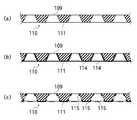
従来の有機膜の成膜では、図8(a)に示すようなマスク110を基板上に配置し、蒸気やスパッタリング粒子等の成膜粒子に、マスク110が有する開口109を通過させ、基板表面に到達させて、基板上にパターニングされた有機膜を形成しているが、マスク110の遮蔽部分となるマスク本体111に成膜粒子が付着し、同図(b)に示すように、マスク110の表面には、有機膜から成る付着膜114が形成されてしまう。
この付着膜114は、開口109の大きさの精度を悪化させたり、剥離してパーティクルになるため、定期的なクリーニングが行われている。In the conventional organic film formation, a
Since the
しかしながら、付着膜114を反応性ガスと化学反応させ、反応生成物を真空排気によって除去するクリーニング方法や、付着膜114にレーザー光を照射し、付着膜114を蒸発させて除去するレーザクリーニング方法では、付着膜114を完全に除去することはできず、同図(c)に示すように、付着膜114の残渣物115が残ってしまう。 However, in the cleaning method in which the
他方、残渣物115が生じないように、例えばレーザー光の強度を強くしてマスク110に照射すると、マスク110の温度が上昇し、マスク110が変形してしまう。
また、残渣物115の蒸発物や、反応性ガスとの反応生成物は真空槽内の残留ガスとなり、基板表面に形成する薄膜中に混入すると、薄膜の品質を悪化させる。On the other hand, for example, when the intensity of laser light is increased to irradiate the
Further, the evaporation product of the
さらに、マスク110を用いて基板表面に無機物膜の薄膜を形成すると、無機物膜とマスク本体111との密着性が強く、反応性ガスやレーザー光では除去できず、マスク110を薄膜製造装置の外部に搬出して、除去作業を行わなければならないという問題がある。 Further, when a thin film of an inorganic film is formed on the substrate surface using the
本発明は上記従来技術の不都合を解決するために創作されたものであり、その目的は、マスクに付着した付着膜を除去し、マスクを再使用できる技術を提供することにある。 The present invention was created in order to solve the above-mentioned disadvantages of the prior art, and an object of the present invention is to provide a technique capable of removing the adhered film adhering to the mask and reusing the mask.
上記課題を解決するため、本発明は、マスク本体の前面に有機薄膜から成る第一の犠牲層が形成された第一のマスクの背面に第一の基板を配置し、真空雰囲気中で、薄膜を形成するための第一の微粒子に前記第一のマスクの貫通孔を通過させ、前記第一の基板の表面に到達させて前記第一の基板の表面にパターニングされた第一の薄膜を形成した後、前記第一のマスクに付着した前記第一の微粒子によって形成された付着膜に、真空雰囲気中でレーザー光を照射し、前記第一の犠牲層を蒸発させて前記付着膜を前記マスク本体から剥離させ、前記マスク本体の前記前面を露出させ、前記マスク本体に犠牲層用微粒子を到達させ、前記マスク本体の前記前面に第二の犠牲層を形成して第二のマスクを構成させ、前記第二のマスクの前記背面に第二の基板を配置して、第二の微粒子に前記第二のマスクの貫通孔を通過させ、パターニングされた第二の薄膜を前記第二の基板の表面に形成する薄膜製造方法である。
また、本発明は、前記第一、第二の微粒子と前記犠牲層用微粒子とを、同じ放出装置から放出させる薄膜製造方法である。
また、本発明は、前記レーザー光は、前記放出装置が配置され、前記第一、第二の薄膜と、前記第二の犠牲層が形成される真空槽内で、前記第一のマスクに照射する薄膜製造方法である。
また、本発明は、前記第二の犠牲層は、前記マスク本体の裏面に冷却板を配置し、前記マスク本体に前記冷却板を密着させた状態で形成する薄膜製造方法である。
また、本発明は、真空槽と、前記真空槽内に配置された放出装置と、前記真空槽内でマスク本体と、前記マスク本体の表面に第一の犠牲層が形成された第一のマスクと、前記マスク本体に第二の犠牲層が形成された第二のマスクとを保持するマスクホルダと、前記真空槽内で基板を保持する基板ホルダと、基板表面に形成する薄膜の原料の微粒子を前記放出装置に供給する薄膜蒸気供給装置と、前記第一のマスクの表面に形成する犠牲層の原料の微粒子を前記放出装置に供給する犠牲層蒸気供給装置と、前記マスクホルダに保持された前記マスク本体にレーザー光を照射するレーザー光照射装置と、を有し、前記放出装置と前記基板は、前記マスク本体を間にして対面できるようにされた薄膜製造装置である。
また、本発明は、前記レーザー光照射装置は、前記レーザー光を射出するレーザー光源と、前記レーザー光源が射出した前記レーザー光を反射させる反射装置とを有し、前記反射装置は反射させる前記レーザー光の進行方向を変化させ、反射した前記レーザー光を前記マスクホルダに保持された前記第一のマスクに照射するように構成され、前記反射装置と、前記マスクホルダに保持された前記第一のマスクとは、相対的に移動するように構成された薄膜製造装置である。In order to solve the above-described problems, the present invention provides a first substrate disposed on the back surface of a first mask in which a first sacrificial layer made of an organic thin film is formed on the front surface of a mask body, and the thin film is formed in a vacuum atmosphere. The first fine particles for forming the first fine particles are passed through the through holes of the first mask to reach the surface of the first substrate to form a patterned first thin film on the surface of the first substrate. After that, the attached film formed by the first fine particles attached to the first mask is irradiated with a laser beam in a vacuum atmosphere to evaporate the first sacrificial layer, and the attached film is applied to the mask. Peeling from the body, exposing the front surface of the mask body, allowing the fine particles for the sacrificial layer to reach the mask body, and forming a second sacrificial layer on the front surface of the mask body to form a second mask. , On the back of the second mask And a substrate disposed, passed through a through hole of the second mask to the second particle, a patterned thin film manufacturing method for forming a second thin film on the surface of the second substrate.
The present invention is also a thin film manufacturing method in which the first and second fine particles and the sacrifice layer fine particles are discharged from the same discharge device.
According to the present invention, the laser beam is applied to the first mask in a vacuum chamber in which the emission device is disposed and the first and second thin films and the second sacrificial layer are formed. This is a thin film manufacturing method.
Moreover, this invention is a thin film manufacturing method which forms a said 2nd sacrificial layer in the state which has arrange | positioned the cooling plate on the back surface of the said mask main body, and contact | adhered the said cooling plate to the said mask main body.
The present invention also provides a vacuum chamber, a discharge device disposed in the vacuum chamber, a mask body in the vacuum chamber, and a first mask in which a first sacrificial layer is formed on the surface of the mask body. And a mask holder for holding a second mask having a second sacrificial layer formed on the mask body, a substrate holder for holding the substrate in the vacuum chamber, and fine particles of a thin film material formed on the substrate surface Held by the mask holder, a thin film vapor supply device for supplying the release device, a sacrificial layer vapor supply device for supplying fine particles of the raw material of the sacrificial layer formed on the surface of the first mask to the discharge device, and the mask holder A laser beam irradiating device for irradiating the mask main body with a laser beam, and the emission device and the substrate are thin film manufacturing apparatuses adapted to face each other with the mask main body in between.
In the present invention, the laser light irradiation device includes a laser light source that emits the laser light, and a reflection device that reflects the laser light emitted from the laser light source, and the laser that the reflection device reflects. The traveling direction of light is changed, and the reflected laser beam is irradiated to the first mask held by the mask holder. The reflection device and the first mask held by the mask holder are configured. A mask is a thin film manufacturing apparatus configured to move relatively.
本発明によれば、マスクに付着した薄膜をマスクを変形させずに除去してマスク本体を露出させ、新しいマスク本体に犠牲層を形成して再使用することができる。
また、反応性ガスを用いずにクリーニングを行うことができるので、真空槽内はダメージを受けないで済む。
また、マスクを大気雰囲気に曝さずに薄膜を除去できるので、真空槽内に不純物が侵入しない。According to the present invention, the thin film adhering to the mask can be removed without deforming the mask to expose the mask body, and a sacrificial layer can be formed on the new mask body for reuse.
Further, since the cleaning can be performed without using the reactive gas, the inside of the vacuum chamber is not damaged.
Moreover, since the thin film can be removed without exposing the mask to the air atmosphere, impurities do not enter the vacuum chamber.
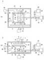
図2(a)、(b)の符号2は、本発明の薄膜製造装置の一例であり、図2(a)はその内部構造を説明するための平面図であり、図2(b)は内部側面図である。 2 (a) and 2 (b) is an example of the thin film manufacturing apparatus of the present invention, FIG. 2 (a) is a plan view for explaining the internal structure, and FIG. FIG.
薄膜製造装置2は真空槽21を有している。
真空槽21の外部には、真空排気装置22が配置されており、真空排気装置22を動作させると、真空槽21内が真空排気され、真空槽21内に真空雰囲気が形成されるように構成されている。The thin
A
真空槽21の壁面には、搬出入口18が設けられており、後述するように、この搬出入口18を通過させて、基板や冷却板を真空槽21内に搬出入することができる。
真空槽21の内部の天井側には、マスクホルダ20と基板ホルダ19とが、下方からこの順序で設けられており、マスクホルダ20にマスクを保持させ、基板ホルダ19に基板を保持させると、基板はマスクの真上に位置するようにされている。The wall surface of the
On the ceiling side inside the
真空槽21の内部の底面側には、放出装置24が配置されており、マスクホルダ20に保持されたマスクは、放出装置24の上方に位置するようにされている。
真空槽21の外部には、蒸発装置23が配置されている。A
An
蒸発装置23は、薄膜蒸気供給装置31を有している。薄膜蒸気供給装置31の内部には、基板表面に形成される薄膜の材料が配置されており、薄膜蒸気供給装置31はこの材料を加熱し、この材料の蒸気を生成するように構成されている。 The
放出装置24は薄膜蒸気供給装置31に接続されており、薄膜蒸気供給装置31が生成した蒸気は、放出装置24に供給される。
放出装置24は、内部が中空にされた筺体42を有しており、放出装置24の鉛直上方を向く表面の部分の筺体42には、複数の放出孔41が形成されている。The
The
放出装置24の筺体42の中空の部分と、真空槽21の内部で放出装置24の外部の雰囲気とは、放出孔41によって接続されており、放出装置24に供給された蒸気は、薄膜形成のための微粒子として、筺体42の中空部分に充満し、複数の放出孔41から真空槽21の内部に放出される。 The hollow portion of the
真空槽21内には、移動装置16が配置されている。移動装置16には、台59が取り付けられており、放出装置24は台59上に取り付けられ、移動装置16によって、水平面内で直線的に往復移動できるように構成されており、放出装置24は、マスクホルダ20に保持されるマスクの真下位置を、直線的に横断する。 A moving
放出装置24には、放出装置24が静止しているときと、移動しているときとの両方で、薄膜蒸気供給装置31から薄膜材料の蒸気が供給されるように構成されており、従って、放出装置24は、移動しながら放出孔41から真空槽21内に蒸気を放出させることができる。 The
薄膜製造装置2によって、基板表面に薄膜を形成する際には、マスクホルダ20と基板ホルダ19とに、マスクと基板を保持させ、放出装置24によって、薄膜材料の蒸気を放出させながら、マスクの下方位置を移動させる。 When the thin
本発明に用いられるマスクを図1(b)の符号10に示す。
マスク10は、金属で構成された板状のマスク本体11を有している。図1(a)はマスク本体11の断面図である。マスク本体11には一乃至複数の貫通孔9が形成されており、マスク本体11の片面には、有機薄膜から成る犠牲層12が形成されている。なお、マスク10はセラミックス等の絶縁物質で構成させてもよい。A mask used in the present invention is indicated by
The
この犠牲層12をマスク本体11に形成する工程を説明する。
先ず、真空槽21内の真空雰囲気を維持しながら、真空槽21に接続されたマスクストッカー室(不図示)から図1(a)のマスク本体11を搬入し、図3(a)、(b)に示すように、薄膜製造装置2内のマスクホルダ20に保持させる。犠牲層12の形成前のマスク本体11を搬入するときから、少なくともマスク本体11へ犠牲層12を形成するまでの間は、真空排気装置22による真空排気を継続し、真空槽21内の真空雰囲気を維持する。A process of forming the
First, while maintaining the vacuum atmosphere in the
蒸発装置23は、基板に薄膜を形成する薄膜蒸気供給装置31に加え、犠牲層12の形成に用いる犠牲層蒸気供給装置32を有している。
犠牲層蒸気供給装置32の内部には、犠牲層12を形成する有機化合物の材料が配置されており、犠牲層蒸気供給装置32はこの材料を加熱し、この材料の蒸気を生成する。犠牲層12の材料は、C、HあるいはC、H、N元素で形成した化合物で構成され、この化合物は、例えば、NPB、CPB、ペンタセン、ペンゾ[b]アントラセン、アントラセン、ナフタリン等である。The
An organic compound material that forms the
薄膜製造装置2は、切替装置33を有している。切替装置33は真空槽21の外部に配置されており、薄膜蒸気供給装置31と犠牲層蒸気供給装置32はこの切替装置33を介して放出装置24に接続されている。 The thin
切替装置33は、放出装置24を、薄膜蒸気供給装置31と犠牲層蒸気供給装置32のうち、いずれか一方又は両方に接続し、又は、接続を遮断するように構成されており、切替装置33によって放出装置24に薄膜蒸気供給装置31が接続されているときは、上述したように、薄膜蒸気供給装置31から放出装置24に基板表面に形成する薄膜の材料蒸気が供給され、放出装置24の内部に薄膜の材料蒸気が充満する。 The switching
他方、切替装置33によって、放出装置24に犠牲層蒸気供給装置32が接続されているときは、犠牲層蒸気供給装置32から放出装置24に犠牲層12の材料蒸気が供給され、放出装置24の内部に犠牲層12の材料蒸気が充満する。 On the other hand, when the sacrificial layer
マスクホルダ20にマスク本体11を配置した後、搬出入口18から真空槽21内に冷却板を搬入し、冷却板を基板ホルダ19上に配置し、基板ホルダ19を降下させて冷却板をマスク本体11上に密着させる。図3(a)、(b)の符号17はマスク本体11上に配置された冷却板を示しており、冷却板17の表面は、貫通孔9の底面に露出されている。 After the mask
放出装置24は、マスク本体11の斜め下方位置に移動させ、マスク本体11の真下には位置しないようにしておき、切替装置33によって、犠牲層蒸気供給装置32を放出装置24に接続し、犠牲層蒸気供給装置32から放出装置24に犠牲層12の材料蒸気を供給し、放出孔41から犠牲層12の材料蒸気を微小粒子として放出させる。 The
なお、犠牲層蒸気供給装置32や薄膜蒸気供給装置31と、放出装置24とを接続する配管には、加熱装置29が密着して取り付けられており、加熱装置29によって配管が温められ、配管の内部を通過する蒸気が析出することはない。 Note that a
薄膜蒸気供給装置31の場合と同様に、放出装置24には、放出装置24が静止しているときと、移動しているときとの両方に、犠牲層蒸気供給装置32から犠牲層12の材料蒸気が供給されるように構成されており、放出装置24を、予めマスクホルダ20に保持されたマスク本体11の真下位置から離間させておき、放出装置24の放出孔41から犠牲層12の蒸気を放出させながら、放出装置24の移動を開始し、図4(a)、(b)に示すように、放出装置24とマスクホルダ20とを、放出装置24を移動させながら対面させる。 As with the thin film
各貫通孔9は、マスク本体11の前面側の開口が大径で、裏面側の開口が小径にそれぞれ形成されており、貫通孔9の内周側面は、放出装置24が移動する経路に面するように傾けられている。 Each through-
図1(b)に示すように、放出装置24が材料蒸気を放出しながら、マスク本体11の真下位置を通過すると、放出装置24から放出された材料蒸気は、放出装置24の真上のマスク本体11が配置された位置に到達し、蒸気の一部は、マスク本体11の前面と貫通孔9の内周側面とに付着し犠牲層12を成長させ、他の一部は、貫通孔9の底面に露出する冷却板17の表面に付着し、その部分に薄膜を成長させる。 As shown in FIG. 1 (b), when the
放出装置24に、一乃至複数回マスク本体11の真下位置を通過させ、犠牲層12が所定膜厚に形成されると、マスク本体11と犠牲層12とを有するマスク10が得られる。
材料蒸気は高温であり、材料蒸気が付着すると、マスク10が加熱されるが、裏面に密着された冷却板17によって吸熱され、マスク10の昇温が大きくならないようにされている。When the
The material vapor is high temperature, and when the material vapor adheres, the
なお、冷却板17の大きさは、貫通孔9が配置された範囲よりも大きくなっており、各貫通孔9内に進入した材料蒸気のうち、裏面側の開口に向かった材料蒸気は、冷却板17に付着し、真空槽21内の、マスク本体11の裏面側には侵入しないようになっている。なお、貫通孔9は犠牲層12によって閉塞されない。 The size of the cooling
犠牲層12が形成された後、犠牲層蒸気供給装置32内での材料蒸気の生成を停止し、冷却板17を搬出入口18から真空槽21の外部に搬出すると、薄膜製造装置2内で、マスク10を用いて基板表面に薄膜を形成できる状態になる。 After the
基板表面への薄膜形成工程を説明すると、真空槽21の上方には、冷却装置8が設けられており、犠牲層12の形成後、真空槽21内の真空雰囲気を維持した状態で、搬出入口18から真空槽21内に搬送ロボットのハンド上に乗せた基板を搬入し、冷却装置8とマスク10との間の位置で一旦静止させ、基板と基板ホルダ19とを接近させ、基板を基板ホルダ19上に配置する。なお、基板表面への薄膜形成中も、真空排気装置22によって真空槽21内を継続して真空排気している。 The thin film formation process on the substrate surface will be described. A
このとき、基板ホルダ19上の基板とマスクホルダ20上のマスク10とは離間しており、位置合わせ装置56によって、基板ホルダ19とマスクホルダ20とを相対的に移動させることで、基板とマスク10とを水平方向に相対的に移動させ、基板とマスク10との位置合わせを行う。
位置合わせ後、基板ホルダ19とマスクホルダ20とを上下方向に相対的に移動させ、基板をマスク10の裏面に密着させる。At this time, the substrate on the
After the alignment, the
図5(a)、(b)の符号13は、基板ホルダ19上で、マスク10に密着された基板を示している。
この状態では、基板13の表面の一部がマスク10の裏面と接触し、基板13の表面の他の一部は、マスク10の貫通孔9の底面に露出される。
In this state, a part of the surface of the
冷却装置8は基板13に接触させ、放出装置24は予めマスクホルダ20上のマスク10の真下位置から離間させておき、薄膜蒸気供給装置31内で基板13表面に形成する薄膜の材料蒸気を生成し、切替装置33により、薄膜蒸気供給装置31を放出装置24に接続し、放出装置24に薄膜の材料蒸気の供給を開始し、放出孔41から供給された材料蒸気を放出しながら放出装置24にマスク10の下方を通過させる。 The
放出孔41は、放出される蒸気が、放出装置24の移動方向とは垂直な方向の一定範囲に帯状に到達するように配置されており、放出された薄膜の材料蒸気は真上方向に進行し、マスク10が配置された位置に到達し、一部は貫通孔9を通過して貫通孔9の底面に露出した基板13の表面に付着して基板13表面に薄膜を成長させ、他の一部はマスク10の放出装置24に向く前面と、貫通孔9の内周側面とに付着する。 The
マスク10の放出装置24に向く前面と、貫通孔9の内周側面とには犠牲層12が予め形成されているから、マスク10に到達した材料蒸気は犠牲層12表面に付着する。
マスク10は、マスク本体11の前面に犠牲層12が形成された後は、マスクホルダ20に対して移動されておらず、マスク本体11の表面のうち、犠牲層12の形成の際に、マスクホルダ20などの真空槽21内の部材によって隠蔽されていて、マスク本体11表面が露出する部分は、基板13の表面に薄膜を形成する際に真空槽21内に露出することはなく、従って、薄膜は、マスク本体11の表面に接触して形成されないようになっている。Since the
After the
図1(d)は、基板13表面に薄膜を形成した後の、基板13とマスク10の断面図であり、同図の符号15は、貫通孔9の底面に露出した基板13の表面に形成された薄膜を示しており、同図の符号14は、犠牲層12の表面に形成された薄膜を示している。 FIG. 1D is a cross-sectional view of the
基板13は、表面に所定の厚みで薄膜15が形成された後、搬出入口18から真空槽21の外部に搬出し、未成膜の基板を搬出入口18から真空槽21内に搬入し、上記手順と同じ手順で薄膜を形成する。 After the
このように薄膜を基板表面に形成する工程を複数回繰り返すと、マスク10上の犠牲層12の表面に形成された薄膜14が厚くなるため、所定枚数の基板に薄膜を形成すると、クリーニングを行い、マスク10の薄膜14を除去する。
ここでは、マスク10のクリーニングは、マスク本体11に犠牲層12を形成し、かつ、基板13の表面に薄膜15を形成した真空槽21の内部で行われる。If the process of forming the thin film on the substrate surface in this manner is repeated a plurality of times, the
Here, the cleaning of the
第一例の薄膜製造装置2は、クリーニングに用いるレーザー光照射装置25を有している。
レーザー光照射装置25は、レーザー光を生成して射出するレーザー光源50と、射出されたレーザー光を反射し、マスク10に照射する反射装置51とを有している。The thin
The laser
レーザー光源50は、真空槽21の内部又は真空槽21の外部に配置されており、真空槽21の外部に配置される場合は、射出したレーザー光は真空槽21に設けられた透明窓部を通過して、真空槽21の内部に入射するようにすればよい。 The
この例では、反射装置51は、放出装置24と共に台59に取り付けられており、移動装置16によって台59が移動されると、反射装置51は、放出装置24と一緒に、マスクホルダ20上のマスク10の真下位置を移動する。なお、反射装置51と放出装置24とは、別々に移動できるようにしてもよい。 In this example, the reflecting
反射装置51とレーザー光源50とは、反射装置51が移動する際にも、レーザー光源50から反射装置51にレーザー光が照射されるように配置されており、ここでは、反射装置51は、受光鏡52と射出鏡53とを有しており、レーザー光源50から射出されたレーザー光は、先ず、受光鏡52に入射して射出鏡53に向かって反射され、射出鏡53に入射してマスク10に向かって反射され、マスク10に入射すると、レーザー光の入射によって、マスク10の表面に、直径1mm程度のレーザスポットが形成される。 The
射出鏡53には、角度制御装置54が設けられており、角度制御装置54によって、射出鏡53の、レーザー光の入射方向に対する反射面の角度が変更され、レーザスポットは、マスク10上を反射装置51の移動方向とは垂直な方向に移動する。
従って、反射装置51の移動と、射出鏡53の角度の変更によって、レーザスポットは、マスク10の前面の露出している部分に隈無く照射することができる。The
Therefore, by moving the reflecting
マスク10の表面には、基板13に成膜した薄膜15と同じ材料の薄膜14が形成されており、レーザー光はこの薄膜14に照射されてレーザスポットを形成すると、レーザスポットの部分と、その周囲の部分が加熱され、薄膜14と、薄膜14の下層の犠牲層12とが昇温する。 A
犠牲層12は、薄膜14よりも低温で蒸発するように設定されており、レーザー光によって犠牲層12が昇温して蒸発すると、犠牲層12表面に位置していた薄膜14はマスク10から落下し、薄膜14がマスク本体11の前面及び貫通孔9の内周側面から剥離され、剥離した部分では、マスク本体11の表面が露出する。 The
マスク10から薄膜14を剥離させる工程を説明すると、レーザー照射する前に、予め、反射装置51をマスク10の下方位置から離間させておき、先ず、冷却装置8を降下させ、マスクホルダ20上のマスク10の裏面に密着させる。 The process of peeling the
この状態は、図5(a)、(b)に示してあり、次いで、反射装置51の移動を開始させる。
反射装置51が移動し、マスク10の外側からマスク10の下方位置に入るところで、レーザー光源50からレーザー光を射出させ、反射装置51で反射してマスク10の表面に照射し、照射された部分とその周囲の犠牲層12を蒸発させ、薄膜14を剥離させる。This state is shown in FIGS. 5A and 5B, and then the movement of the reflecting
When the reflecting
図6(a)、(b)は、マスク10にレーザー光60を照射している状態である。
角度制御装置54によって、マスク10の前面と貫通孔9の内周面とを含む表面上のレーザー光60の照射位置は、反射装置51の移動方向とは垂直な方向に移動されており、マスク10の表面上で帯状の範囲に照射されると共に、反射装置51の移動によって、マスク10の前面上で、帯状の範囲が、帯が伸びる方向とは垂直な方向に移動し、マスク10の反射装置51と対面する範囲にレーザー光60が照射され、マスク10の前面と貫通孔9の内周側面に付着する薄膜14を剥離させ、マスク本体11の表面を露出させる。6A and 6B show a state in which the
The irradiation position of the
冷却装置8は昇降装置6に取り付けられており、上下移動可能に構成されており、レーザー光がマスク10に照射される際には、予め冷却装置8が降下され、冷却装置8の底面は、マスク10の裏面と密着されており、レーザー光が照射されて加熱されるマスク10から、冷却された冷却装置8に熱が流れて、マスク10が冷却されるようになっている。 The
冷却装置8には、真空槽21の外部に配置された冷却媒体源7が接続されており、冷却媒体源7によって冷却された冷却媒体が冷却媒体源7と冷却装置8の間を循環して流れるようにされており、冷却装置8に移動した熱は、冷却媒体源7によって冷却媒体から除去されるようになっている。 A cooling
犠牲層12と薄膜14とが除去されたマスク本体11は、放出装置24から材料蒸気の放出によって、新しい犠牲層12が形成されると、基板表面への薄膜の形成に用いることができるようになる。 The
なお、マスク10の下方の、真空槽21の底面上には、図示しないトレイが予め配置されており、マスク10から落下した薄膜14は、トレイ上に落下して、真空槽21の内部から取り出すことができるようにされている。 Note that a tray (not shown) is disposed in advance on the bottom surface of the
マスク10にレーザー光60を照射して、犠牲層12を蒸発させる際、反射装置51の移動に後続して放出装置24を移動させるようにすれば、反射装置51によって犠牲層12が蒸発され、マスク本体11の前面及び貫通孔9の内周側面が露出された後、後続する放出装置24が犠牲層12を形成する材料蒸気を放出しながら、露出された前面及び内周側面の真下位置に到達すると、マスク本体11の前面と貫通孔9の内周側面に新しい、犠牲層12が形成される。 When the
犠牲層12が形成されているときに、反射装置51にレーザー光が入射され、反射されてマスク10表面に照射されており、マスク10上の犠牲層12と薄膜14とが除去されている。この場合、マスク10の犠牲層12と薄膜14を除去しながら、同じマスク10の露出されたマスク本体11の表面に新しい犠牲層12を形成することになり、作業効率が高い。 When the
以上により、マスク本体11を真空槽21の外部に搬出することなく、マスク本体11への犠牲層の形成と、犠牲層を有するマスクを用いた基板表面への薄膜の形成と、マスクに付着した薄膜の除去とを繰り返し行うことができる。 As described above, the sacrificial layer is formed on the mask
なお、上記実施例の薄膜製造装置2では、放出装置24を移動させていたが、マスクや基板と同程度の面積の範囲に放出孔が配置された放出装置を用い、放出装置を静止させて、犠牲層や薄膜を形成してもよい。その場合の薄膜製造装置の反射装置は、上記実施例の薄膜製造装置の反射装置と同じ移動をするようにしておくと、犠牲層や薄膜を形成する真空槽の内部で、マスク上の犠牲層と、犠牲層に付着した薄膜を除去することができる。 In the thin
また、図7の符号3に示した第二例の薄膜製造装置のように、搬送ロボット70が配置された搬送室69に、レーザー光照射装置を有するクリーニング室63と、マスク上に配置された基板の表面に薄膜を形成する薄膜形成室64と、マスクに設けられた犠牲層を除去し、露出されたマスク本体の表面に新しい犠牲層を形成するクリーニング室63と、搬出入室68と、エッチング室や薄膜製造室である他の処理室65〜67が接続されている。 Moreover, like the thin film manufacturing apparatus of the 2nd example shown by the code |
各室63〜69の内部は真空排気されており、薄膜形成室64には、薄膜蒸気供給装置38と、犠牲層蒸気供給装置39とが接続されており、薄膜形成室64内で搬送ロボット70によって基板を搬入し、上記第一例の薄膜製造装置2で説明した工程と同じ工程で、薄膜蒸気供給装置38から基板に形成する薄膜の材料蒸気を放出させ、基板の表面に薄膜を形成し、処理室65〜68のうちの搬出入室から外部に搬出し、新しい基板を搬入する。基板の搬出前に他の処理室65〜68で真空処理を行っても良い。 Each
薄膜が付着されたマスクは、搬送ロボット70によって、薄膜形成室64からクリーニング室63に移動させ、クリーニング室63の内部でマスクにレーザー光を照射し、犠牲層を蒸発させ、犠牲層表面の薄膜を除去し、マスク本体を露出させる。 The mask with the thin film attached is moved from the thin
マスク本体は、クリーニング室63から薄膜形成室64内に移動させ、上記第一例の薄膜製造装置2で説明した工程と同じ工程で、犠牲層蒸気供給装置39から犠牲層の材料蒸気を放出させマスク本体に犠牲層を形成する。
搬出入室68以外の各室63〜67、69は、内部の真空雰囲気が維持されており、マスクやマスク本体が、薄膜形成とクリーニングと犠牲層形成とが行われる間に大気に曝されることはない。The mask main body is moved from the cleaning
The
以上は、蒸着法によって基板表面に有機薄膜を形成したが、本発明で薄膜形成に用いる微粒子は蒸気に限定されるものでは無く、スパッタリング粒子や、他の微粒子であっても、犠牲層を有機薄膜で形成すると、レーザー照射によって蒸発させることができるので、犠牲層の表面上の無機薄膜を除去することができる。 The organic thin film was formed on the substrate surface by the vapor deposition method as described above. However, the fine particles used for forming the thin film in the present invention are not limited to vapor. When formed as a thin film, it can be evaporated by laser irradiation, so that the inorganic thin film on the surface of the sacrificial layer can be removed.
犠牲層として用いる有機薄膜は、80℃〜300℃の温度範囲で1×10⁻²Pa以上の蒸気圧有する有機化合物であれば、基板表面に薄膜を形成するときにマスクが昇温しても犠牲層は蒸発せず、且つ、レーザー光を照射することで蒸発させやすい。If the organic thin film used as the sacrificial layer is an organic compound having a vapor pressure of 1 × 10⁻² Pa or higher in the temperature range of 80 ° C. to 300 ° C., even if the temperature of the mask is increased when the thin film is formed on the substrate surface. The sacrificial layer does not evaporate and is easily evaporated by irradiation with laser light.
レーザー光をマスクに溶射して犠牲層を蒸発させる際、Arガス、Heガス、Neガス等の希ガス雰囲気中やN2ガス雰囲気中にマスクを配置してもよい。
また、レーザー光の波長は、犠牲層の吸収率が高い波長に設定しておくと、犠牲層を蒸発させやすい。When the sacrificial layer is evaporated by spraying laser light on the mask, the mask may be disposed in a rare gas atmosphere such as Ar gas, He gas, Ne gas, or N2 gas atmosphere.
Further, if the wavelength of the laser beam is set to a wavelength at which the sacrificial layer has a high absorptance, the sacrificial layer can be easily evaporated.
2、3……薄膜製造装置
9……貫通孔
10……マスク
11……マスク本体
12……犠牲層
13……基板
14……薄膜
15……薄膜
17……冷却板
19……基板ホルダ
20……マスクホルダ
24……放出装置
31、38……薄膜蒸気供給装置
32、39……犠牲層蒸気供給装置
25……レーザー光照射装置
2, 3 ... Thin
Claims (6)
Translated fromJapanese前記第一のマスクに付着した前記第一の微粒子によって形成された付着膜に、真空雰囲気中でレーザー光を照射し、前記第一の犠牲層を蒸発させて前記付着膜を前記マスク本体から剥離させ、前記マスク本体の前記前面を露出させ、
前記マスク本体に犠牲層用微粒子を到達させ、前記マスク本体の前記前面に第二の犠牲層を形成して第二のマスクを構成させ、前記第二のマスクの前記背面に第二の基板を配置して、第二の微粒子に前記第二のマスクの貫通孔を通過させ、パターニングされた第二の薄膜を前記第二の基板の表面に形成する薄膜製造方法。The first substrate is disposed on the back of the first mask on which the first sacrificial layer made of an organic thin film is formed on the front surface of the mask body, and the first fine particles for forming the thin film are formed in a vacuum atmosphere. After passing through the through hole of the first mask and reaching the surface of the first substrate to form a patterned first thin film on the surface of the first substrate,
The attached film formed by the first fine particles attached to the first mask is irradiated with laser light in a vacuum atmosphere, the first sacrificial layer is evaporated, and the attached film is peeled off from the mask body. And exposing the front surface of the mask body,
Sacrificial layer fine particles reach the mask body, a second sacrificial layer is formed on the front surface of the mask body to form a second mask, and a second substrate is formed on the back surface of the second mask. A method of manufacturing a thin film, wherein the second fine particle is disposed and passed through the through hole of the second mask to form a patterned second thin film on the surface of the second substrate.
前記真空槽内に配置された放出装置と、
前記真空槽内でマスク本体と、前記マスク本体の表面に第一の犠牲層が形成された第一のマスクと、前記マスク本体に第二の犠牲層が形成された第二のマスクとを保持するマスクホルダと、
前記真空槽内で基板を保持する基板ホルダと、
基板表面に形成する薄膜の原料の微粒子を前記放出装置に供給する薄膜蒸気供給装置と、
前記第一のマスクの表面に形成する犠牲層の原料の微粒子を前記放出装置に供給する犠牲層蒸気供給装置と、
前記マスクホルダに保持された前記マスク本体にレーザー光を照射するレーザー光照射装置と、
を有し、
前記放出装置と前記基板は、前記マスク本体を間にして対面できるようにされた薄膜製造装置。A vacuum chamber;
A discharge device disposed in the vacuum chamber;
A mask body, a first mask having a first sacrificial layer formed on the surface of the mask body, and a second mask having a second sacrificial layer formed on the mask body are held in the vacuum chamber. A mask holder to
A substrate holder for holding the substrate in the vacuum chamber;
A thin film vapor supply device for supplying thin film raw material fine particles to be formed on the substrate surface to the discharge device;
A sacrificial layer vapor supply device for supplying fine particles of the raw material of the sacrificial layer formed on the surface of the first mask to the discharge device;
A laser beam irradiation device for irradiating the mask body held by the mask holder with a laser beam;
Have
A thin film manufacturing apparatus in which the discharge device and the substrate can face each other with the mask body in between.
前記反射装置は反射させる前記レーザー光の進行方向を変化させ、反射した前記レーザー光を前記マスクホルダに保持された前記第一のマスクに照射するように構成され、
前記反射装置と、前記マスクホルダに保持された前記第一のマスクとは、相対的に移動するように構成された請求項5記載の薄膜製造装置。The laser light irradiation device has a laser light source that emits the laser light, and a reflection device that reflects the laser light emitted by the laser light source,
The reflection device is configured to change a traveling direction of the laser beam to be reflected, and to irradiate the first mask held by the mask holder with the reflected laser beam,
The thin film manufacturing apparatus according to claim 5, wherein the reflection device and the first mask held by the mask holder are configured to move relatively.
Priority Applications (1)
| Application Number | Priority Date | Filing Date | Title |
|---|---|---|---|
| JP2011278823AJP5875851B2 (en) | 2011-12-20 | 2011-12-20 | Thin film manufacturing method, thin film manufacturing apparatus |
Applications Claiming Priority (1)
| Application Number | Priority Date | Filing Date | Title |
|---|---|---|---|
| JP2011278823AJP5875851B2 (en) | 2011-12-20 | 2011-12-20 | Thin film manufacturing method, thin film manufacturing apparatus |
Publications (2)
| Publication Number | Publication Date |
|---|---|
| JP2013129866Atrue JP2013129866A (en) | 2013-07-04 |
| JP5875851B2 JP5875851B2 (en) | 2016-03-02 |
Family
ID=48907661
Family Applications (1)
| Application Number | Title | Priority Date | Filing Date |
|---|---|---|---|
| JP2011278823AActiveJP5875851B2 (en) | 2011-12-20 | 2011-12-20 | Thin film manufacturing method, thin film manufacturing apparatus |
Country Status (1)
| Country | Link |
|---|---|
| JP (1) | JP5875851B2 (en) |
Cited By (3)
| Publication number | Priority date | Publication date | Assignee | Title |
|---|---|---|---|---|
| WO2017158946A1 (en)* | 2016-03-18 | 2017-09-21 | コニカミノルタ株式会社 | Organic electroluminescent element patterning method and patterning device |
| JP2018076602A (en)* | 2018-01-31 | 2018-05-17 | 大日本印刷株式会社 | Vapor deposition mask and organic semiconductor device manufacturing method |
| WO2018155421A1 (en)* | 2017-02-21 | 2018-08-30 | 株式会社アルバック | Formation method of resin film and deposition device of resin film |
Citations (11)
| Publication number | Priority date | Publication date | Assignee | Title |
|---|---|---|---|---|
| JPH07145472A (en)* | 1993-11-22 | 1995-06-06 | Murata Mfg Co Ltd | Mask for forming thin film and its washing method |
| JPH1053857A (en)* | 1996-08-08 | 1998-02-24 | Mitsubishi Kagaku Kk | Masking jig and its regenerating method |
| US20020011205A1 (en)* | 2000-05-02 | 2002-01-31 | Shunpei Yamazaki | Film-forming apparatus, method of cleaning the same, and method of manufacturing a light-emitting device |
| JP2002060926A (en)* | 2000-05-02 | 2002-02-28 | Semiconductor Energy Lab Co Ltd | Film deposition apparatus, and cleaning method thereof |
| JP2002241925A (en)* | 2001-02-21 | 2002-08-28 | Ulvac Japan Ltd | Organic vapor deposition system, and organic thin film manufacturing method |
| JP2003313654A (en)* | 2001-12-12 | 2003-11-06 | Semiconductor Energy Lab Co Ltd | Film forming apparatus, film forming method and cleaning method |
| JP2004300495A (en)* | 2003-03-31 | 2004-10-28 | Nippon Seiki Co Ltd | Evaporation mask and evaporation method using the same |
| JP2006063446A (en)* | 2004-08-25 | 2006-03-09 | Samsung Sdi Co Ltd | Organic vapor deposition equipment |
| US20060110904A1 (en)* | 2004-11-23 | 2006-05-25 | Advantech Global, Ltd | Multiple shadow mask structure for deposition shadow mask protection and method of making and using same |
| US20080081115A1 (en)* | 2001-12-12 | 2008-04-03 | Semiconductor Energy Laboratory Co., Ltd. | Film formation apparatus and film formation method and cleaning method |
| JP2008088483A (en)* | 2006-09-29 | 2008-04-17 | Tokyo Electron Ltd | Vapor deposition apparatus and operation method thereof |
- 2011
- 2011-12-20JPJP2011278823Apatent/JP5875851B2/enactiveActive
Patent Citations (11)
| Publication number | Priority date | Publication date | Assignee | Title |
|---|---|---|---|---|
| JPH07145472A (en)* | 1993-11-22 | 1995-06-06 | Murata Mfg Co Ltd | Mask for forming thin film and its washing method |
| JPH1053857A (en)* | 1996-08-08 | 1998-02-24 | Mitsubishi Kagaku Kk | Masking jig and its regenerating method |
| US20020011205A1 (en)* | 2000-05-02 | 2002-01-31 | Shunpei Yamazaki | Film-forming apparatus, method of cleaning the same, and method of manufacturing a light-emitting device |
| JP2002060926A (en)* | 2000-05-02 | 2002-02-28 | Semiconductor Energy Lab Co Ltd | Film deposition apparatus, and cleaning method thereof |
| JP2002241925A (en)* | 2001-02-21 | 2002-08-28 | Ulvac Japan Ltd | Organic vapor deposition system, and organic thin film manufacturing method |
| JP2003313654A (en)* | 2001-12-12 | 2003-11-06 | Semiconductor Energy Lab Co Ltd | Film forming apparatus, film forming method and cleaning method |
| US20080081115A1 (en)* | 2001-12-12 | 2008-04-03 | Semiconductor Energy Laboratory Co., Ltd. | Film formation apparatus and film formation method and cleaning method |
| JP2004300495A (en)* | 2003-03-31 | 2004-10-28 | Nippon Seiki Co Ltd | Evaporation mask and evaporation method using the same |
| JP2006063446A (en)* | 2004-08-25 | 2006-03-09 | Samsung Sdi Co Ltd | Organic vapor deposition equipment |
| US20060110904A1 (en)* | 2004-11-23 | 2006-05-25 | Advantech Global, Ltd | Multiple shadow mask structure for deposition shadow mask protection and method of making and using same |
| JP2008088483A (en)* | 2006-09-29 | 2008-04-17 | Tokyo Electron Ltd | Vapor deposition apparatus and operation method thereof |
Cited By (6)
| Publication number | Priority date | Publication date | Assignee | Title |
|---|---|---|---|---|
| WO2017158946A1 (en)* | 2016-03-18 | 2017-09-21 | コニカミノルタ株式会社 | Organic electroluminescent element patterning method and patterning device |
| WO2018155421A1 (en)* | 2017-02-21 | 2018-08-30 | 株式会社アルバック | Formation method of resin film and deposition device of resin film |
| KR20190058598A (en)* | 2017-02-21 | 2019-05-29 | 가부시키가이샤 아루박 | Method of forming resin film and apparatus for forming resin film |
| JPWO2018155421A1 (en)* | 2017-02-21 | 2019-11-07 | 株式会社アルバック | Resin film forming method and resin film forming apparatus |
| KR102249249B1 (en) | 2017-02-21 | 2021-05-07 | 가부시키가이샤 아루박 | Resin film forming method and resin film forming apparatus |
| JP2018076602A (en)* | 2018-01-31 | 2018-05-17 | 大日本印刷株式会社 | Vapor deposition mask and organic semiconductor device manufacturing method |
Also Published As
| Publication number | Publication date |
|---|---|
| JP5875851B2 (en) | 2016-03-02 |
Similar Documents
| Publication | Publication Date | Title |
|---|---|---|
| JP5282038B2 (en) | Vapor deposition equipment | |
| US8802200B2 (en) | Method and apparatus for cleaning organic deposition materials | |
| JP6114636B2 (en) | Drying apparatus and drying processing method | |
| JPWO2012053532A1 (en) | Organic film forming apparatus and organic film forming method | |
| US20120082778A1 (en) | Vacuum deposition system and vacuum deposition method | |
| JP5875851B2 (en) | Thin film manufacturing method, thin film manufacturing apparatus | |
| JP3839674B2 (en) | Organic vapor deposition apparatus and organic thin film manufacturing method | |
| US10886128B2 (en) | Method and apparatus for manufacturing vapor deposition mask | |
| JP2004079528A5 (en) | ||
| JP7117396B2 (en) | Film forming apparatus and film forming method | |
| JP5877955B2 (en) | Vapor deposition apparatus and vapor deposition method | |
| JP5816067B2 (en) | Thin film manufacturing method and thin film manufacturing apparatus | |
| WO2012081625A1 (en) | Manufacturing method for organic electroluminescent device, manufacturing device for organic electroluminescent device, manufacturing method for optoelectronic converter, and manufacturing device for optoelectronic converter | |
| JP2012197468A5 (en) | ||
| JP5412338B2 (en) | Mask cleaning apparatus, cleaning method, and organic EL manufacturing apparatus | |
| JP4969832B2 (en) | Film forming apparatus and panel manufacturing method | |
| JP5836974B2 (en) | Display device manufacturing apparatus and display device manufacturing method | |
| JP5478324B2 (en) | Cleaning apparatus, film forming apparatus, and film forming method | |
| JPS59126774A (en) | Vapor phase metal depositing device | |
| JP2020147787A (en) | Film deposition device | |
| KR100980258B1 (en) | Dome for fixing deposition products used in multilayer film deposition equipment | |
| JP5703439B2 (en) | Method for forming metal plate and osmium film | |
| JP5209954B2 (en) | Deposition processing jig and plasma CVD apparatus | |
| KR100578559B1 (en) | Thin Film Deposition Apparatus and Thin Film Deposition Method Improved Bonding Force and Deposition Rate Simultaneously | |
| JPH06116708A (en) | Method and apparatus for manufacturing laser film |
Legal Events
| Date | Code | Title | Description |
|---|---|---|---|
| A621 | Written request for application examination | Free format text:JAPANESE INTERMEDIATE CODE: A621 Effective date:20141009 | |
| A977 | Report on retrieval | Free format text:JAPANESE INTERMEDIATE CODE: A971007 Effective date:20150610 | |
| A131 | Notification of reasons for refusal | Free format text:JAPANESE INTERMEDIATE CODE: A131 Effective date:20150721 | |
| A521 | Request for written amendment filed | Free format text:JAPANESE INTERMEDIATE CODE: A821 Effective date:20150918 Free format text:JAPANESE INTERMEDIATE CODE: A523 Effective date:20150918 | |
| TRDD | Decision of grant or rejection written | ||
| A01 | Written decision to grant a patent or to grant a registration (utility model) | Free format text:JAPANESE INTERMEDIATE CODE: A01 Effective date:20160105 | |
| A61 | First payment of annual fees (during grant procedure) | Free format text:JAPANESE INTERMEDIATE CODE: A61 Effective date:20160120 | |
| R150 | Certificate of patent or registration of utility model | Ref document number:5875851 Country of ref document:JP Free format text:JAPANESE INTERMEDIATE CODE: R150 | |
| R250 | Receipt of annual fees | Free format text:JAPANESE INTERMEDIATE CODE: R250 | |
| R250 | Receipt of annual fees | Free format text:JAPANESE INTERMEDIATE CODE: R250 | |
| R250 | Receipt of annual fees | Free format text:JAPANESE INTERMEDIATE CODE: R250 | |
| R250 | Receipt of annual fees | Free format text:JAPANESE INTERMEDIATE CODE: R250 | |
| R250 | Receipt of annual fees | Free format text:JAPANESE INTERMEDIATE CODE: R250 | |
| R250 | Receipt of annual fees | Free format text:JAPANESE INTERMEDIATE CODE: R250 | |
| R250 | Receipt of annual fees | Free format text:JAPANESE INTERMEDIATE CODE: R250 |