JP2013125260A - Wavelength selection switch - Google Patents
Wavelength selection switchDownload PDFInfo
- Publication number
- JP2013125260A JP2013125260AJP2011275812AJP2011275812AJP2013125260AJP 2013125260 AJP2013125260 AJP 2013125260AJP 2011275812 AJP2011275812 AJP 2011275812AJP 2011275812 AJP2011275812 AJP 2011275812AJP 2013125260 AJP2013125260 AJP 2013125260A
- Authority
- JP
- Japan
- Prior art keywords
- elliptical
- optical system
- selective switch
- wavelength selective
- input
- Prior art date
- Legal status (The legal status is an assumption and is not a legal conclusion. Google has not performed a legal analysis and makes no representation as to the accuracy of the status listed.)
- Pending
Links
Images


Classifications
- G—PHYSICS
- G02—OPTICS
- G02B—OPTICAL ELEMENTS, SYSTEMS OR APPARATUS
- G02B26/00—Optical devices or arrangements for the control of light using movable or deformable optical elements
- G02B26/02—Optical devices or arrangements for the control of light using movable or deformable optical elements for controlling the intensity of light
Landscapes
- Physics & Mathematics (AREA)
- General Physics & Mathematics (AREA)
- Optics & Photonics (AREA)
- Mechanical Light Control Or Optical Switches (AREA)
- Optical Modulation, Optical Deflection, Nonlinear Optics, Optical Demodulation, Optical Logic Elements (AREA)
Abstract
Description
Translated fromJapanese本発明は、異なる波長の光を分岐可能な波長選択スイッチに関する。 The present invention relates to a wavelength selective switch that can split light of different wavelengths.
従来、複数の入出力光ポートを有する波長選択スイッチを光波長多重通信に用いることが知られている。近年のネットワークの大規模化に対して、広い透過帯域を有し、入出力ポートの数の多い波長選択スイッチが求められている。ビームエクスパンダを用いて偏向素子にビームを楕円形上に集光することにより、広い透過帯域を有する波長選択スイッチが提案されている(特許文献1参照)。 Conventionally, it is known to use a wavelength selective switch having a plurality of input / output optical ports for optical wavelength division multiplexing communication. In response to the recent increase in the scale of networks, a wavelength selective switch having a wide transmission band and a large number of input / output ports is required. A wavelength selective switch having a wide transmission band has been proposed by converging a beam on an ellipse on a deflecting element using a beam expander (see Patent Document 1).
特許文献1に記載の波長選択スイッチおよび従来の波長選択スイッチでは、分散部により分散される複数の光線の分散方向すべてに垂直な第1の方向に沿って、複数の入出力ポートが配置される。波長選択スイッチを薄型化するためには、第1の方向に沿った入出力ポートの配置可能な数には上限がある。そこで、第1の方向に垂直な第2の方向にも沿った2次元状に、入出力ポートを配置することにより入出力ポート数を増加させることが考えられる。 In the wavelength selective switch described in Patent Document 1 and the conventional wavelength selective switch, a plurality of input / output ports are arranged along a first direction perpendicular to all the dispersion directions of the plurality of light beams dispersed by the dispersion unit. . In order to reduce the thickness of the wavelength selective switch, there is an upper limit to the number of input / output ports that can be arranged along the first direction. Therefore, it is conceivable to increase the number of input / output ports by arranging the input / output ports in a two-dimensional manner along a second direction perpendicular to the first direction.
しかし、入出力ポートを2次元状に配置した場合には、波長選択スイッチの薄型化と信号光の出力の高効率化を同時に実現させることが困難であった。 However, when the input / output ports are arranged two-dimensionally, it has been difficult to simultaneously realize a thin wavelength selective switch and a high efficiency of signal light output.
従って、上記のような問題点に鑑みてなされた本発明では、入出力ポートを2次元状に配置しながら、薄型化と信号光の出力の高効率化を同時に実現可能な波長選択スイッチの提供を目的とする。 Therefore, in the present invention made in view of the above problems, a wavelength selective switch capable of simultaneously realizing thinning and high efficiency of signal light output while arranging input / output ports in two dimensions. With the goal.
上述した諸課題を解決すべく、本発明による波長選択スイッチは、
波長多重された信号光を入力または出力させる複数の入出力部を、2次元状に配置した入出力ユニットと、
入出力部から入力される光信号を、第1の平面に沿って波長に応じた方向に分散可能な分散部と、
分散部により波長毎に分散され得る複数の信号光それぞれを、波長毎に異なる前記入出力部に入射するように偏向する複数の偏向素子を有する偏向ユニットと、
入出力ユニットおよび分散部の間に設けられ、光軸に垂直な第1の方向の屈折力が光軸および第1の方向に垂直な第2の方向の屈折力より大きい第1の楕円化光学素子を少なくとも一つと第2の方向の屈折力が第1の方向の屈折力より大きい第2の楕円化光学素子を少なくとも一つとを有し、第1の方向が第1の平面に垂直になるように第1の楕円化光学素子および第2の楕円化光学素子とを配置した楕円化リレー光学系とを備え、
楕円化リレー光学系は、
偏向ユニットと共役となる共役点の中で、偏向ユニットおよび楕円化リレー光学系の間で最も楕円化リレー光学系に近い共役点である第1の共役点に、すべての入出力部から入力され得る信号光を集光し、
楕円化リレー光学系から分散部側に射出した信号光の第1の方向に沿ったビームウェストの形成位置を第1の共役点に一致させ、
第2の方向においては、すべての入出力部から入力し得る信号光を楕円リレー光学系内の第1の集光点に集光させ、第1の集光点と前記第1の共役点を共役にし、
偏向素子に入射する信号光のビーム形状を楕円化する
ことを特徴とするものである。In order to solve the above-described problems, the wavelength selective switch according to the present invention includes:
An input / output unit in which a plurality of input / output units for inputting or outputting wavelength-multiplexed signal light are arranged two-dimensionally; and
A dispersion unit capable of dispersing an optical signal input from the input / output unit in a direction according to the wavelength along the first plane;
A deflection unit having a plurality of deflection elements that deflect each of the plurality of signal lights that can be dispersed for each wavelength by the dispersion unit so as to be incident on the input / output unit different for each wavelength;
A first ovalization optical system provided between the input / output unit and the dispersion unit, wherein the refractive power in the first direction perpendicular to the optical axis is greater than the refractive power in the second direction perpendicular to the optical axis and the first direction. Having at least one element and at least one second elliptical optical element having a refractive power in the second direction greater than that in the first direction, the first direction being perpendicular to the first plane An elliptical relay optical system in which the first elliptical optical element and the second elliptical optical element are arranged,
The elliptical relay optical system
Input from all input / output units to the first conjugate point that is closest to the ellipsoidal relay optical system among the conjugate points that are conjugate to the deflection unit. To collect the signal light
The beam waist formation position along the first direction of the signal light emitted from the ovalization relay optical system toward the dispersion portion is matched with the first conjugate point,
In the second direction, the signal light that can be input from all the input / output units is condensed on the first condensing point in the elliptical relay optical system, and the first condensing point and the first conjugate point are Conjugate,
It is characterized in that the beam shape of the signal light incident on the deflection element is made elliptical.
上記のように構成された本発明に係る波長選択スイッチによれば、波長選択スイッチの薄型化と、信号光の出力の高効率化とを同時に実現可能である。 According to the wavelength selective switch according to the present invention configured as described above, it is possible to simultaneously achieve a reduction in the thickness of the wavelength selective switch and an increase in the output efficiency of the signal light.
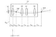
以下、本発明を適用した波長選択スイッチのある態様に係る実施形態について、図面を参照して説明する。図1は、本発明の第1の実施形態に係る波長選択スイッチの概略構成を示す上面図である。図2は、図1を側面から見た光路の展開図である。 Hereinafter, an embodiment according to an aspect of a wavelength selective switch to which the present invention is applied will be described with reference to the drawings. FIG. 1 is a top view showing a schematic configuration of a wavelength selective switch according to the first embodiment of the present invention. FIG. 2 is a development view of the optical path when FIG. 1 is viewed from the side.
波長選択スイッチ10は、入出力ユニット11、マイクロレンズアレイ12、楕円化リレー光学系13、凹面ミラー14、分散部15、偏向部16などを含んで構成される。なお、波長選択スイッチ10には互いに垂直なxyz軸を有する3次元座標が定められ、各部位はxyz軸に基づいて配置される。 The wavelength
図3に示すように、入出力ユニット11は、x軸方向(第2の方向)およびy軸方向(第1の方向)に沿った行列状に配置された光ファイバにより構成される入力ポート11aと出力ポート11b〜11oとを備える。なお、現実の波長選択スイッチの光路中に、図示しないミラー、プリズム等の偏向部材が光路を折り曲げるために配置されている場合には、x方向及びy方向との説明は、このような偏向部材が無いものとした仮想的な光学系を前提として用いられることとする。 As shown in FIG. 3, the input /
入力ポート11a及び出力ポート11b〜11oは、それぞれ、波長選択スイッチ10の外部からの波長多重された多重信号光を入力させ、また、外部へ信号光を出力させるものである。以下、説明の便宜上、入力ポート11a及び出力ポート11b〜11oを、適宜、入出力ポート11a〜11o(入出力部)とまとめて表記する。 The input port 11a and the output ports 11b to 11o are used to input wavelength-multiplexed multiplexed signal light from the outside of the wavelength
各光ファイバの一端は波長選択スイッチ10内にあり、他端は波長選択スイッチ10の外部と接続される。また、出力ポートの数を入力ポートの数よりも多数設けることも、入力ポートの数を出力ポートの数よりも多数設けることもできる。また、入力ポート及び出力ポートの数が複数で異なっていてもよい。ただし、図1〜図3においては、説明の都合から、行列列に配置された15の入出力ポート11a〜11oのみを図示しているが、入出力ポートの数は図に記載の入出力ポートの数に限定されない。何れの入出力ポート11a〜11oを、入力用または出力用として用いるかは、適宜設計することが可能である。必ずしも、全入出力ポート11a〜11oを入力または出力に用いる必要は無く、入力ポートまたは出力ポートとして機能していない入出力ポートが存在してもよい。 One end of each optical fiber is in the wavelength
各入出力ポート11a〜11oとマイクロレンズアレイ12に設けられる各マイクロレンズは対となるように、入出力ユニット11とマイクロレンズアレイ12は配置される。各マイクロレンズは、入力ポート11aから入力される光を平行光束に変換し、また、出力ポート11b〜11oに向けて出力される平行光束を光ファイバに入射させる。なお、各マイクロレンズに平行光束に変換、すなわちコリメートされた光はマイクロレンズの光軸に垂直な平面Pbw(以後、“形成面”と呼ぶ)上にビームウェストを形成する(図1、図2参照)。なお、マイクロレンズアレイ12に設けられる各マイクロレンズは、球面であっても非球面であってもよい。The input /
また、入力ポート11aとマイクロレンズとを通って波長選択スイッチ10内に入力された光、及び、出力ポート11b〜11oのそれぞれに対応するマイクロレンズに向けて出力される光は、それぞれ互いに平行な光束となる。 Further, the light input into the wavelength
楕円化リレー光学系13は、5行3列に配置された入出力ポート11a〜11oの中の中心の入出力ポート11hと光軸が一致するように配置される。楕円化リレー光学系13は、z軸に平行な入射光線を一次集光点PCP(第1の共役点)に集光する。したがって、何れかの入出力ポート11a〜11oから入射した光は、楕円化リレー光学系13により一次集光点PCPに集光する。また、楕円化リレー光学系13は、入出力ポート11a〜11oから入射するスポット状の光をy軸方向が長軸となる楕円形状に変換する。このような機能を発生させる楕円化リレー光学系13の構成については、後に詳細に説明する。 The elliptical relay
凹面ミラー14は、一次集光点PCPから凹面ミラー14までの距離が凹面ミラー14の焦点距離f1となるように、配置される。また、凹面ミラー14は、凹面ミラー14と楕円化リレー光学系13との光軸を含む平面がxz平面に平行となるように、配置される。このような構成により、凹面ミラー14は一次集光点PCPを通過した光をy軸に垂直な方向に偏向する(図2参照)。 The
分散部15は、凹面ミラー14から分散部15までの距離が凹面ミラー14の焦点距離f1となるように、配置される。分散部15は、例えばy軸に平行な格子が分散面上に形成された反射型回折格子である。分散部15としては、波長毎の光の分解性能が高くより分散角が大きいものが望ましい。 The
凹面ミラー14を反射した入力光は、y軸に略垂直な光となって分散部15に入射し、図1に示すように、分散部15の分散面において波長毎に異なる角度で分散される。すなわち、分散部15は入力光を波長毎の信号光に分離する。各信号光はxz平面(第1の平面)上の方向に分離される。分散部15によって分散された信号光は、同時に分散部15によって凹面ミラー14に反射される。 The input light reflected from the
なお、凹面ミラー14で信号光を反射し、分散部15には入力光を分散面に斜めに入射させて回折させるが、簡単のために、図2では入出力ユニット11から偏向部16に至る光路を、直線的に示している。 The signal light is reflected by the
偏向部16は、凹面ミラー14から偏向部16間での距離が凹面ミラー14の焦点距離f1となるように、配置される。このような配置により、図1に示すように、分散部15で分散された波長毎の信号光は、凹面ミラー14により各信号光の主光線が平行な光線となって、偏向部16に入射する。The
なお、図2に示すように、一次集光点PCPと偏向部16とはx軸方向(第2の方向)においては共役なので、一次集光点PCPを通過した入力光は、分散部15で分散された後、偏向部16においてxz平面における楕円化リレー光学系13の光軸の位置に集光する。 As shown in FIG. 2, since the primary condensing point PCP and the deflecting
図4に示すように、偏向部16には複数の偏向素子16a〜16nが設けられる。分散部15で分散された波長毎の信号光は、それぞれ偏向素子16a〜16nの何れかに入射する。偏向部16は、例えば、MEMSミラーアレイであり、偏向素子16a〜16nはMEMSミラーアレイを構成する複数のマイクロミラーである。各偏向素子16a〜16nは、y軸方向に長辺を有する矩形である。偏向素子16a〜16nは、xz平面に平行な配列方向に沿って直列に配置される(図1参照)。 As shown in FIG. 4, the
なお、図4において、偏向部16には、14の偏向素子16a〜16nが図示されているが、偏向素子の数は14に限定されない。また、偏向素子16a〜16nの各ミラー面の配置間隔、形状、および面積は同じでも異なっていてもよい。 In FIG. 4, 14
それぞれの偏向素子16a〜16nは独立に制御され、傾きを変えることが出来る。偏向素子16a〜16nの傾きは、y軸に平行な直線および配列方向に平行な直線を軸に回動可能である。偏向素子16a〜16nをy軸に平行な直線を軸に回動させることにより、信号光を伝達する出力ポート11b〜11oのx軸方向に沿った位置を変えることが可能である。また、偏向素子16a〜16nを配列方向に平行な直線を軸に回動させることにより、信号光を伝達する出力ポート11b〜11oのy軸方向に沿った位置を変えることが可能である。 Each of the deflecting
各偏向素子16a〜16nにより反射された波長毎の信号光は、それぞれ凹面ミラー14を通り分散部15で回折され、入力光と反対方向の光路を経て、入出力ユニット11の出力ポート11b〜11oの何れかに出力される。なお、何れの入出力ポート11a〜11oを入力用または出力用として用いるかは、適宜設計することが可能である。 The signal light for each wavelength reflected by the deflecting
ここで、複数の偏向素子16a〜16nに入射した信号光のうち、少なくとも1つの波長の信号光を入出力ポート11hから出力する場合は、対応する偏向素子16a〜16nの偏向方向を制御して、図1、図2に破線で示すように、所定の方向に特定の波長の光を反射させる。偏向素子16a〜16nによって反射された特定波長の光は、凹面ミラー14、分散部15、楕円化リレー光学系13、マイクロレンズアレイ12を経て、入出力ポート11hから出力される。同じ入出力ポート11hに出力する波長の光が複数ある場合は、それら複数の波長の光が分散部15で合波される。 Here, when the signal light having at least one wavelength is output from the input / output port 11h among the signal lights incident on the plurality of
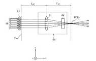
次に、楕円化リレー光学系13の構成について説明する。図5、図6に示すように、楕円化リレー光学系13は、第1のシリンドリカルレンズ17、第2のシリンドリカルレンズ18、第3のシリンドリカルレンズ19、および第4のシリンドリカルレンズ20を含んで構成される。 Next, the configuration of the ovalization relay
入出力ユニット11側から一次集光点PCPまでの間において、第2のシリンドリカルレンズ18、第3のシリンドリカルレンズ19、第1のシリンドリカルレンズ17、および第4のシリンドリカルレンズ20が順番に配置される。第2〜第4のシリンドリカルレンズ18〜20は、光軸面が一致し、その光軸面内に一次集光点PCPが形成されるように配置される。また、第1のシリンドリカルレンズ17は、その光軸面内に一次集光点PCPが形成されるように配置される。なお、上述の楕円化リレー光学系13の光軸とは、第2〜第4のシリンドリカルレンズ18〜20の光軸面と、第1のシリンドリカルレンズ17の光軸面とが交わる直線によって定義される。 Between the input /
図5に示すように、第1のシリンドリカルレンズ17(第1の楕円化光学素子)はy軸方向のみに光束を縮める。すなわち、y軸方向にのみ屈折力を有するレンズである。第1のシリンドリカルレンズ17は、ビームウェストの形成される形成面Pbwから第1のシリンドリカルレンズ17までの距離、および第1のシリンドリカルレンズ17から一次集光点PCPまでの距離が第1のシリンドリカル17のyz平面における焦点距離fy1となるように、配置される(図5参照)。As shown in FIG. 5, the first cylindrical lens 17 (first elliptical optical element) contracts the light beam only in the y-axis direction. That is, the lens has a refractive power only in the y-axis direction. The first
したがって、yz平面において、何れかの入出力ポート11a〜11oから入力された信号光は第1のシリンドリカルレンズ17までz軸に平行に進行し、第1のシリンドリカルレンズ17によって一次集光点PCPに集光する。また、yz平面におけるビームウェストが一次集光点PCPに形成される。 Accordingly, in the yz plane, the signal light input from any of the input / output ports 11a to 11o travels to the first
図6に示すように、第2〜第4のシリンドリカルレンズ18〜20はx軸方向に光束を縮める。すなわち、x軸方向にのみ屈折力を有するレンズである。第2〜第4のシリンドリカルレンズ18〜20のxz平面における焦点距離は、それぞれfx1、fx2、およびfx3である。なお、第2〜第4のシリンドリカルレンズ18〜20のxz平面における焦点距離の合計が、実質的に第1のシリンドリカルレンズ17のyz平面における焦点距離fy1と一致するように、第2〜第4のシリンドリカルレンズ18〜20は設計される。すなわち、(1)式が満たされる。As shown in FIG. 6, the second to fourth

第2のシリンドリカルレンズ18は、ビームウェストの形成される形成面Pbwから第2のシリンドリカルレンズ18までの距離が第2のシリンドリカルレンズ18のxz平面における焦点距離fx1となるように配置される。したがって、xz平面において、何れかの入出力ポート11a〜11oから入力された信号光は第2のシリンドリカルレンズ18までz軸に平行に進行し、第2のシリンドリカルレンズ18によってxz平面における中間集光点ICP(第1の集光点)に集光する。なお、中間集光点ICPは第2のシリンドリカルレンズ18から第2のシリンドリカルレンズ18のxz平面における焦点距離fx1だけ離れている。The second
第3のシリンドリカルレンズ19は、xz平面における中間集光点ICPから第3のシリンドリカルレンズ19までの距離が第3のシリンドリカルレンズ19のxz平面における焦点距離fx2となるように配置される。さらに、第4のシリンドリカルレンズ20は、第3のシリンドリカルレンズ19から第4のシリンドリカルレンズ20までの距離が、第3のシリンドリカルレンズ19および第4のシリンドリカルレンズのxz平面における焦点距離の合計(fx2+fx3)に等しくなるように、配置される。The third
なお、前述のように、第2〜第4のシリンドリカルレンズ18〜20のxz平面における焦点距離の合計(fx1+fx2+fx3)が、第1のシリンドリカルレンズ17のyz平面における焦点距離fy1と一致するので、第4のシリンドリカルレンズ20から一次集光点PCPまでの距離は、第4のシリンドリカルレンズ20のxz平面における焦点距離fx3に等しい。したがって、xz平面における中間集光点ICPと一次集光点PCPとはx軸方向(第2の方向)においては共役となる。As described above, the total focal length (fx1 + fx2 + fx3 ) of the second to fourth
上述のような第2〜第4のシリンドリカルレンズ18〜20の配置により、xz平面において、何れかの入出力ポート11a〜11oから入力された信号光は一次集光点PCPに集光する。さらに、xz平面におけるビームウェストが一次集光点PCPに形成される。 With the arrangement of the second to fourth
以上のような構成の第1の実施形態の波長選択スイッチ10によれば、入出力ポート11a〜11oを2次元状に配置しながら、波長選択スイッチ10の薄型化と信号光の出力の高効率化を同時に実現させることが可能である。このような効果について、以下に詳細に説明する。 According to the wavelength
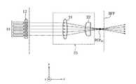
特許文献1に記載の発明における波長選択スイッチでは、第1の実施形態における楕円化リレー光学系13の代わりに、図7に示す球面レンズ21とシリンドリカルレンズ22によって構成される楕円化光学系23が用いられる。なお、楕円化光学系23では、形成面Pbwから球面レンズ21までの距離、および球面レンズ21からyz平面における一次集光点PCPyz(以下、“yz集光点”と呼ぶ)までの距離が、球面レンズ21の焦点距離fy2に一致するように、球面レンズ21が配置される。In the wavelength selective switch in the invention described in Patent Document 1, an elliptical
楕円化光学系23を備えた波長選択スイッチの入出力ポートを2次元状に配置する場合には、以下のような問題が生じる。シリンドリカルレンズ22はy軸方向に屈折力を有しないため、yz集光点PCPyzは球面レンズ21の後側焦点位置に一致する。一方、図8に示すように、シリンドリカルレンズ22はx軸方向に屈折力を有するため、xz平面における一次集光点PCPxz(以下、“xz集光点”と呼ぶ)は、球面レンズ21の後側焦点位置BFPよりもシリンドリカルレンズ22側に近づく。When the input / output ports of the wavelength selective switch including the ovalization
このように、xz集光点PCPxzおよびyz集光点PCPyzが一致しないため、何れかの入出力ポートから入力される光をxz平面およびyz平面の何れにおいても同じ位置に集光させることできない。そのため、任意の入出力ポートから入力される光を他の入出力ポートから出力させることが出来ない。As described above, since the xz condensing point PCPxz and the yz condensing point PCPyz do not coincide with each other, the light input from any of the input / output ports is condensed at the same position in both the xz plane and the yz plane. Can not. Therefore, light input from any input / output port cannot be output from another input / output port.
そこで、図9(a)、9(b)に示すように、y軸方向にのみ屈折力を有する第5のシリンドリカルレンズ24と、x軸方向にのみ屈折力を有する第6のシリンドリカルレンズ25とを有する楕円化光学系26を、楕円化光学系23の代わりに用いることが考えられる。 Therefore, as shown in FIGS. 9A and 9B, a fifth
楕円化光学系26では、第5のシリンドリカルレンズ24から、形成面Pbwおよび一次集光点PCPまでの距離が、第5のシリンドリカルレンズ24のyz平面における焦点距離fy3に一致するように、第5のシリンドリカルレンズ24が設計され、配置される。また、第6のシリンドリカルレンズ25から一次集光点PCPまでの距離が、第6のシリンドリカルレンズ25のxz平面における焦点距離fx4に一致するように、第6のシリンドリカルレンズ25が配置される。In the ovalization
このような構成によれば、xz平面およびyz平面における信号光の集光点が一次集光点PCPに一致するので、何れかの入出力ポートから入力される光をxz平面およびyz平面の何れにおいても同じ位置に集光させることが可能となる。 According to such a configuration, the condensing point of the signal light in the xz plane and the yz plane coincides with the primary condensing point PCP. Can be condensed at the same position.
ただし、このような構成では、第2のシリンドリカルレンズ25のxz平面における前側焦点位置FFPと形成面PbwにはΔSのズレが生じる。そのため、一次集光点PCPにおける信号光のx軸方向の径が一次集光点近傍に形成されるビームウェストのx軸方向の径より太い。したがって、入出力ポートに入力された信号光を、他の入出力ポートから高効率で出力することが難しい。However, with such a configuration, a deviation of ΔS occurs between the front focal position FFP and the formation surfacePbw in the xz plane of the second
ただし、ビームウェストの形成位置が一次集光点PCPからずれていても、一次集光点PCPにおけるビームの径とビームウェストの径との差が小さければ、信号光を高効率で出力することが可能である。一次集光点PCPにおけるビームの径とビームウェストの径との差を縮小するためには、ビームウェストの径を拡大することが考えられる。 However, even if the beam waist formation position is deviated from the primary condensing point PCP, if the difference between the beam diameter and the beam waist diameter at the primary condensing point PCP is small, the signal light can be output with high efficiency. Is possible. In order to reduce the difference between the beam diameter and the beam waist diameter at the primary focusing point PCP, it is conceivable to increase the beam waist diameter.
図10(a)、10(b)に示すように、ビームウェストの径dに対して、ビームウェストの形成位置から離れた位置におけるビームの径Dの比D/dは、ビームウェストの径dが大きくなるほど、小さくなる。それゆえ、集光点近傍に形成されるビームウェストの径を大きくすることにより、集光点におけるビームの径とビームウェストの径との差が縮小される。したがって、第5および第6のシリンドリカルレンズ24、25の何れかによって対応する方向の径の大きなビームウェストを形成することにより、出力される信号光の高効率化を図ることが可能である。 As shown in FIGS. 10A and 10B, the ratio D / d of the beam diameter D at a position away from the beam waist formation position with respect to the beam waist diameter d is the beam waist diameter d. The larger the is, the smaller it becomes. Therefore, by increasing the diameter of the beam waist formed in the vicinity of the condensing point, the difference between the beam diameter and the beam waist diameter at the condensing point is reduced. Therefore, by forming a beam waist having a large diameter in the corresponding direction by any of the fifth and sixth
ところで、波長選択スイッチにおける信号光の透過帯域の拡大化のためには、偏向素子16a〜16nの配列方向に対応するx軸方向におけるビームの径が細いことが好ましい。また、波長選択スイッチの薄型化のためには、y軸方向におけるビームの径が太いことが好ましい。 By the way, in order to expand the transmission band of signal light in the wavelength selective switch, it is preferable that the beam diameter in the x-axis direction corresponding to the arrangement direction of the deflecting
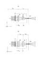
それゆえ、x軸方向におけるビーム径を細く維持しながらy軸方向におけるビームの径を太くすることが考えられる。このような作用を奏するために、図11に示す楕円化光学系27を、図9に示す楕円化光学系26の代わりに用いることが考えられる。 Therefore, it is conceivable to increase the beam diameter in the y-axis direction while maintaining a small beam diameter in the x-axis direction. In order to achieve such an effect, it is conceivable to use the ovalization
楕円化光学系27では、第7のシリンドリカルレンズ28から一次集光点PCPまでの距離が、第7のシリンドリカルレンズ28のyz平面における焦点距離fy4に一致するように、第7のシリンドリカルレンズ28が配置される。また、第8のシリンドリカルレンズ29から、形成面Pbwおよび一次集光点PCPまでの距離が、第8のシリンドリカルレンズ29のxz平面における焦点距離fx5に一致するように、第8のシリンドリカルレンズ29が設計され、配置される。In the ovalization
このような構成において、yz平面におけるビームウェストの径dに対するyz集光点におけるビームの径Dの比D/dが1.2未満であれば、出力される信号光の高効率化を図ることが可能である。ただし、このような条件を満たすと、一次集光点PCPにおいて形成されるビームのアスペクト比を大きくすることが難しい。アスペクト比が小さい場合には、波長選択スイッチの薄型化が困難となる。 In such a configuration, if the ratio D / d of the beam diameter D at the yz condensing point to the beam waist diameter d in the yz plane is less than 1.2, the efficiency of the output signal light is improved. Is possible. However, if these conditions are satisfied, it is difficult to increase the aspect ratio of the beam formed at the primary condensing point PCP. When the aspect ratio is small, it is difficult to reduce the thickness of the wavelength selective switch.
一般的に、任意の焦点距離である第8のシリンドリカルレンズ29に対して、第7のシリンドリカルレンズ28のyz平面における焦点距離を変えることにより、yz平面におけるD/dおよび一次集光点PCPにおけるアスペクト比が変動する。 In general, by changing the focal length of the seventh
例えば、図12に示すように、焦点距離が0.35mmである第8のシリンドリカルレンズ29を用いた場合に、比D/dを1.2未満の範囲に留まらせる第7のシリンドリカルレンズ28のyz平面における焦点距離は0.34〜0.37であって、この焦点距離の範囲では、ビームのアスペクト比は1.1〜1.3程度である。 For example, as shown in FIG. 12, when the eighth
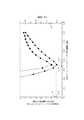
また、図13に示すように、焦点距離が1.0mmである第8のシリンドリカルレンズ29を用いた場合に、比D/dを1.2未満の範囲に留まらせる第7のシリンドリカルレンズ28のyz平面における焦点距離は0.9〜1.2であって、この焦点距離の範囲では、ビームのアスペクト比は1.1〜1.4程度である。 Further, as shown in FIG. 13, when the eighth
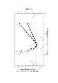
また、図14に示すように、焦点距離が3.0mmである第8のシリンドリカルレンズ29を用いた場合に、比D/dを1.2未満の範囲に留まらせる第7のシリンドリカルレンズ28のyz平面における焦点距離は2.3〜4.2であって、この焦点距離の範囲では、ビームのアスペクト比は0.8〜1.2程度である。 Further, as shown in FIG. 14, when the eighth
このように、比D/dを1.2未満に抑える場合には、入出力ポートを1次元状に配置したときに得られる10位のアスペクト比を得ることが出来ず、波長選択スイッチの薄型化が難しかった。 As described above, when the ratio D / d is suppressed to less than 1.2, the tenth aspect ratio obtained when the input / output ports are arranged one-dimensionally cannot be obtained, and the wavelength selective switch is thin. It was difficult to convert.
一方、本実施形態では、xz平面において中間集光点ICPに信号光を集光させ、中間集光点ICPと一次集光点PCPとをx軸方向(第2の方向)において共役にすることにより、xz平面における信号光を一次集光点PCPに集光させている。このような構成においては、x軸方向に屈折力を有する複数のシリンドリカルレンズを用いることが可能である。複数のシリンドリカルレンズを用いることが可能であれば、いずかのシリンドリカルレンズにおいては焦点距離を任意に設定できる。したがって、以下に説明するように、一次集光点PCPにおける信号光のアスペクト比を任意に設定可能となる。具体的には、アスペクト比を2以上に設定することが可能である。 On the other hand, in the present embodiment, the signal light is condensed on the intermediate condensing point ICP in the xz plane, and the intermediate condensing point ICP and the primary condensing point PCP are conjugated in the x-axis direction (second direction). Thus, the signal light in the xz plane is condensed on the primary condensing point PCP. In such a configuration, a plurality of cylindrical lenses having refractive power in the x-axis direction can be used. As long as a plurality of cylindrical lenses can be used, the focal length can be arbitrarily set in any of the cylindrical lenses. Therefore, as described below, the aspect ratio of the signal light at the primary condensing point PCP can be arbitrarily set. Specifically, the aspect ratio can be set to 2 or more.
マイクロレンズアレイ12により形成されるビームウェストの半径をω1、信号光の波長をλとすると、一次集光点PCPにおける信号光のy軸に沿った半径ωy1は、(2)式により算出される。When the radius of the beam waist formed by the
中間集光点ICPにおける信号光のx軸に沿った半径ωx1は、(3)式により算出される。The radius ωx1 along the x axis of the signal light at the intermediate condensing point ICP is calculated by the equation (3).
さらに、一次集光点PCPにおける信号光のx軸に沿った半径ωx2は、(3)式で算出された中間集光点ICPにおける信号光の半径ωx1を用いて、(4)式により算出される。Further, the radius ωx2 along the x-axis of the signal light at the primary condensing point PCP is obtained by the equation (4) using the radius ωx1 of the signal light at the intermediate condensing point ICP calculated by the equation (3). Calculated.
(1)、(3)式に基づいて、一次集光点PCPにおける信号光のアスペクト比Hは、(5)式により算出される。 Based on the equations (1) and (3), the aspect ratio H of the signal light at the primary condensing point PCP is calculated by the equation (5).
(5)式を、(1)式を用いて変形させることにより、(6)式が得られる。 By transforming equation (5) using equation (1), equation (6) is obtained.
(6)式から分かるように、一次集光点PCPにおける信号光のアスペクト比を所望の値に合わせることが可能なので、波長選択スイッチ10を薄型化することが可能である。 As can be seen from the equation (6), since the aspect ratio of the signal light at the primary condensing point PCP can be adjusted to a desired value, the wavelength
さらに、xz平面においてもyz平面においても一次集光点PCPにビームウェストが形成されるので、信号光の高効率な出力を実現可能である。 Furthermore, since a beam waist is formed at the primary condensing point PCP in both the xz plane and the yz plane, it is possible to realize a highly efficient output of signal light.
次に、第2の実施形態に係る波長選択スイッチについて説明する。第2の実施形態では第1のシリンドリカルレンズの構成が第1の実施形態と異なっている。以下に、第1の実施形態と異なる点を中心に第2の実施形態について説明する。なお、第1の実施形態と同じ機能及び構成を有する部位には同じ符号を付して、その説明を省略する。 Next, a wavelength selective switch according to the second embodiment will be described. In the second embodiment, the configuration of the first cylindrical lens is different from that of the first embodiment. The second embodiment will be described below with a focus on differences from the first embodiment. In addition, the same code | symbol is attached | subjected to the site | part which has the same function and structure as 1st Embodiment, and the description is abbreviate | omitted.
第2の実施形態では、第1のシリンドリカルレンズ以外の波長選択スイッチの各部位の構成及び機能は第1の実施形態と同じである。 In the second embodiment, the configuration and function of each part of the wavelength selective switch other than the first cylindrical lens are the same as those in the first embodiment.
図15に示すように、第1の実施形態と同様に、楕円化リレー光学系130は、第1のシリンドリカルレンズ170および第2〜第4のシリンドリカルレンズ18〜20を含んで構成される。 As shown in FIG. 15, as in the first embodiment, the ovalization relay
第1のシリンドリカルレンズ170はy軸方向のみに光束を縮める。第1の実施形態と同様に、第1のシリンドリカルレンズ170は、第1のシリンドリカルレンズ170から一次集光点PCPまでの距離が第1のシリンドリカルレンズ170のyz平面における焦点距離fy5となるように、配置される。第1の実施形態と異なり、形成面Pbwと第1のシリンドリカルレンズ170の前側焦点位置FFPとはΔZ離間している。ΔZが(7)式を満たすように、第1のシリンドリカルレンズ170が設計される。The first
以上のような構成の第2の実施形態の波長選択スイッチによっても、第1の実施形態と同じく、入出力ポートを2次元状に配置しながら、波長選択スイッチ10の薄型化と信号光の出力の高効率化を同時に実現させることが可能である。このような効果について、以下に詳細に説明する。 Also with the wavelength selective switch of the second embodiment having the above-described configuration, the wavelength
一次集光点PCPと一次集光点PCPからyz平面におけるビームウェストの形成位置までの距離をZとすると、yz平面における比D/dは(8)式により算出される。 When the distance from the primary condensing point PCP and the primary condensing point PCP to the formation position of the beam waist in the yz plane is Z, the ratio D / d in the yz plane is calculated by the equation (8).
前述のように、yz平面における比D/dが1.2未満であれば、出力される信号光の高効率化を図ることが可能である。したがって、比D/dを1.2未満にするには一次集光点PCPとビームウェストの形成位置との距離Zは、(9)式を満たす必要がある。 As described above, if the ratio D / d in the yz plane is less than 1.2, it is possible to increase the efficiency of the output signal light. Therefore, in order to make the ratio D / d less than 1.2, the distance Z between the primary condensing point PCP and the formation position of the beam waist needs to satisfy the equation (9).
一次集光点PCPと第1のシリンドリカルレンズ170によるビームウェストの形成位置との距離Zを用いると、ΔZは(10)式により算出される。 Using the distance Z between the primary condensing point PCP and the position where the beam waist is formed by the first
(10)式の右辺を整理すると、(11)式が得られる。
(9)式と(11)式により、(7)式が得られる。 Equation (7) is obtained from Equation (9) and Equation (11).
したがって、(7)式を満たすことにより、yz平面におけるビームウェストの径dに対する一次集光点PCPにおけるビームのy軸方向の径Dの比D/dが1.2未満となる。それゆえ、第2の実施形態の波長選択スイッチによっても、信号光の出力の高効率化を図ることが可能である。 Therefore, by satisfying the equation (7), the ratio D / d of the diameter D in the y-axis direction of the beam at the primary condensing point PCP to the diameter d of the beam waist in the yz plane becomes less than 1.2. Therefore, the wavelength selective switch of the second embodiment can also increase the efficiency of signal light output.
また、第2の実施形態によれば、第1の実施形態と異なり、(1)式を満たす必要が無く、(1)式より制約の少ない(11)式を満たせばよいので、一次集光点PCPにおける信号光のアスペクト比をさらに自由に設定可能である。したがって、波長選択スイッチ10の薄型化を図ることが可能である。 Further, according to the second embodiment, unlike the first embodiment, it is not necessary to satisfy the expression (1), and it is sufficient to satisfy the expression (11) with fewer restrictions than the expression (1). The aspect ratio of the signal light at the point PCP can be set more freely. Therefore, it is possible to reduce the thickness of the wavelength
次に、本発明の第3の実施形態に係る波長選択スイッチについて説明する。第3の実施形態では第1、第3、および第4のシリンドリカルレンズの代わりの凹面シリンドリカルミラーを用いている点および第2のシリンドリカルレンズのxz平面における焦点距離に制約が設けられる点において第1の実施形態と異なっている。以下に、第1の実施形態と異なる点を中心に第3の実施形態について説明する。なお、第1の実施形態と同じ機能及び構成を有する部位には同じ符号を付し、その説明を省略する。 Next, a wavelength selective switch according to the third embodiment of the present invention will be described. In the third embodiment, the first is that a concave cylindrical mirror is used instead of the first, third, and fourth cylindrical lenses, and that the focal length in the xz plane of the second cylindrical lens is limited. This is different from the embodiment. The third embodiment will be described below with a focus on differences from the first embodiment. In addition, the same code | symbol is attached | subjected to the site | part which has the same function and structure as 1st Embodiment, and the description is abbreviate | omitted.
第3の実施形態では、第1、第3、および第4のシリンドリカルレンズ以外の波長選択スイッチの各部位の構成及び機能は第1の実施形態と同じである。 In the third embodiment, the configuration and function of each part of the wavelength selective switch other than the first, third, and fourth cylindrical lenses are the same as those in the first embodiment.
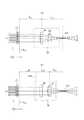
図16に示すように、楕円化リレー光学系131は、第1のシリンドリカルミラー30、第2のシリンドリカルレンズ181、第2のシリンドリカルミラー31を含んで構成される。図17、18を用いて、第1のシリンドリカルミラー30および第2のシリンドリカルミラー31の配置などについて説明する。図17は楕円化リレー光学系131を側面から見た光路の展開図であり、図18は楕円化リレー光学系131を上面から見た光路の展開図である。 As illustrated in FIG. 16, the ovalization relay
第1のシリンドリカルミラー30はy軸方向のみに屈折力を有する凹面ミラーである。図17に示すように、第1のシリンドリカルミラー30は、第2の実施形態における第1のシリンドリカルレンズ170と同じ作用を奏するように用いられ、x軸から見て光軸に平行な光線を焦点に集光する作用を有する。第1のシリンドリカルミラー30から一次集光点PCPまでの距離が第1のシリンドリカルミラー30のyz平面における焦点距離fy6と等しくなるように、第1のシリンドリカルミラー30は配置される。The first
第1の実施形態と同様に、第2のシリンドリカルレンズ181はx軸方向のみに屈折力を有するシリンドリカルレンズである。第2のシリンドリカルレンズ181の配置は、第1の実施形態における第2のシリンドリカルレンズ18と同じである。第1の実施形態と異なり、第2のシリンドリカルレンズ181のxz平面における焦点距離fx6が、(12)式を満たすように、第2のシリンドリカルレンズ181は設計される。ここで、楕円化リレー光学系131を構成するx軸方向のみに屈折力を有するシリンドリカルレンズのうち、第2のシリンドリカルレンズ181の屈折力が最大である。Similar to the first embodiment, the second
第2のシリンドリカルミラー31はx軸方向にのみ屈折力を有する凹面シリンドリカルミラーである。図18に示すように、第2のシリンドリカルミラー31は、第2の実施形態における第3および第4のシリンドリカルレンズ19、20と同じ作用を奏するように用いられ、y軸から見て光軸に平行な光線を焦点に集光する作用を有する。 The second
図16、18に示すように、第2のシリンドリカルミラー31から、xz平面における中間集光点ICP、第1のシリンドリカルミラー30、および一次集光点PCPまでのそれぞれの間の距離が第2のシリンドリカルミラー31のxz平面における焦点距離fx7と等しくなるように、第2のシリンドリカルミラー31は設計され、配置される。したがって、(13)式が成立する。As shown in FIGS. 16 and 18, the distances from the second
以上のような構成の第3の実施形態の波長選択スイッチによっても、第1の実施形態と同じく、入出力ポートを2次元状に配置しながら、波長選択スイッチ10の薄型化と信号光の出力の高効率化を同時に実現させることが可能である。このような効果について、以下に詳細に説明する。 Even with the wavelength selective switch of the third embodiment having the above-described configuration, the wavelength
第2の実施形態と同じく、yz平面における比D/dが1.2未満であれば、出力される信号光の高効率化を図ることが可能である。 As in the second embodiment, if the ratio D / d in the yz plane is less than 1.2, it is possible to increase the efficiency of the output signal light.
第3の実施形態では、(13)式を満たしているので、一次集光点PCPから中間集光点ICPまでの距離と一次集光点PCPから第1のシリンドリカルミラー30の前側焦点位置FFPまでの距離とが等しく、(15)式が満たされる。したがって、(14)、(15)式から、(12)式が得られる。 In the third embodiment, since Expression (13) is satisfied, the distance from the primary focal point PCP to the intermediate focal point ICP and the primary focal point FFP to the front focal position FFP of the first
したがって、(12)式を満たすことにより、yz平面におけるビームウェストの径dに対する一次集光点PCPにおけるビームのy軸方向の径Dの比D/dが1.2未満となる。それゆえ、第3の実施形態の波長選択スイッチによっても、信号光の出力の高効率化を図ることが可能である。 Therefore, by satisfying the expression (12), the ratio D / d of the diameter D in the y-axis direction of the beam at the primary condensing point PCP to the diameter d of the beam waist in the yz plane becomes less than 1.2. Therefore, the wavelength selective switch of the third embodiment can also increase the efficiency of signal light output.
また、第3の実施形態によれば、第1の実施形態と異なり、(1)式を満たす必要が無く、(1)式より制約の少ない(12)、(13)式を満たせばよいので、一次集光点PCPにおける信号光のアスペクト比をさらに自由に設定可能である。したがって、波長選択スイッチ10の薄型化を図ることが可能である。 Also, according to the third embodiment, unlike the first embodiment, it is not necessary to satisfy the expression (1), and it is sufficient to satisfy the expressions (12) and (13), which are less restricted than the expression (1). The aspect ratio of the signal light at the primary condensing point PCP can be set more freely. Therefore, it is possible to reduce the thickness of the wavelength
また、第3の実施形態によれば、第1および第2の実施形態における第3および第4のシリンドリカルレンズ19、20を共通化しているので、波長選択スイッチ10の構成部品数を減らすことが可能となる。 Further, according to the third embodiment, since the third and fourth
本発明を諸図面や実施形態に基づき説明してきたが、当業者であれば本開示に基づき種々の変形や修正を行うことが容易であることに注意されたい。すなわち、各部材、各手段等に含まれる機能等は論理的に矛盾しないように再配置可能であり、複数の部材や手段等を1つに組合わせたり、或いは分割したりすることが可能である。従って、これらの変形や修正は本発明の範囲に含まれることに留意されたい。 Although the present invention has been described based on the drawings and embodiments, it should be noted that those skilled in the art can easily make various changes and modifications based on the present disclosure. In other words, the functions included in each member, each means, etc. can be rearranged so as not to be logically contradictory, and a plurality of members, means, etc. can be combined or divided into one. is there. Therefore, it should be noted that these variations and modifications are included in the scope of the present invention.
例えば、上記の第1〜第3の実施形態では、光軸に平行な信号光をx軸方向において楕円化リレー光学系13、130、131内のxz平面における中間集光点ICPに集光させ、xz平面における中間集光点ICPを一次集光点PCPと共役にする構成であるが、xz平面における中間集光点ICPは1箇所に限定されない。x軸方向における複数の中間集光点を設け、一次集光点PCPまで共役になるようにリレーする構成であってもよい。さらに、x軸方向における少なくとも一つの中間集光点があれば、光軸に平行な信号光をy軸方向においても楕円化リレー光学系13、130、131内の中間集光点に集光させてもよい。このような構成であっても、一次集光点PCPにおける信号光のアスペクト比を任意の値に設定可能である。 For example, in the first to third embodiments described above, the signal light parallel to the optical axis is condensed on the intermediate condensing point ICP in the xz plane in the elliptical relay
第1の実施形態における第1のシリンドリカルレンズ17とは別にy軸方向のみに屈折力を有する光学素子が設けられる場合には、y軸方向のみに屈折力を有するすべての光学素子のyz平面における焦点距離の合計と、x軸方向のみに屈折力を有するすべての光学素子のxz平面における焦点距離の合計とが一致すれば、第1の実施形態と同じ効果が得られる。 In the case where an optical element having a refractive power only in the y-axis direction is provided separately from the first
第2の実施形態における第1のシリンドリカルレンズ170とは別にy軸方向のみに屈折力を有する光学素子が設けられる場合には、y軸方向のみに屈折力を有するすべての光学素子の焦点距離の合計より、x軸方向のみに屈折力を有するすべての光学素子の焦点距離の合計が長ければ、第2の実施形態と同じ効果が得られる。 In the case where an optical element having refractive power only in the y-axis direction is provided separately from the first
第3の実施形態における第1のシリンドリカルミラー30とは別にy軸方向のみに屈折力kを有する光学素子が設けられる場合には、y軸方向のみに屈折力を有するすべての光学素子のyz平面における焦点距離の合計が、x軸方向のみに屈折力を有するすべての光学素子のxz平面における焦点距離の合計とx軸方向のみに屈折力を有する光学素子の中で屈折力が最大である光学素子との差分に等しければ、第3の実施形態と同様の効果が得られる。 In the case where an optical element having a refractive power k only in the y-axis direction is provided separately from the first
また、第1〜第3の実施形態では、マイクロレンズアレイ12を配置しているが、必ずしも、マイクロレンズアレイ12を配置する必要はない。 In the first to third embodiments, the
また、第1〜第3の実施形態では、楕円化リレー光学系13、130、131はシリンドリカルレンズおよびシリンドリカルミラーのように、一方の方向にのみ屈折力を有する光学素子を含んで構成される。しかし、x軸方向およびy軸方向それぞれの屈折力が大きく異なる光学系を用いても、本実施形態と同様の波長選択スイッチを構成可能である。 In the first to third embodiments, the elliptical relay
また、第1〜第3の実施形態では、分散部15は反射型回折格子であるが、透過型回折格子、グリズム、イマージョングレーティング、スーパープリズム等であってもよく、複数の分散素子を組合わせてもよい。さらに、第1〜第3の実施形態では、凹面ミラー14を用いて一次集光点PCPと偏向部16とを共役にする構成であるが、凸レンズや回折型集光素子等の集光作用を奏する部材を用いてもよい。例えば、図19に示すように、透過型回折格子である分散部152および凸レンズ142a、142bを用いても本実施形態と同様の効果を有する波長選択スイッチを構成可能である。 In the first to third embodiments, the
また、第1〜第3の実施形態では、偏向部16はMEMSミラーアレイであるが、液晶素子、光学結晶、反射型の液晶表示パネルであるLCOS(Liquid Crystal On Silicon)などの他の偏向素子を用いてもよい。 In the first to third embodiments, the deflecting
10 波長選択スイッチ
11 入出力ユニット
12 マイクロレンズアレイ
13、130、131 楕円化リレー光学系
14 凹面ミラー
15、152 分散部
16 偏向部
17 第1のシリンドリカルレンズ
18、181 第2のシリンドリカルレンズ
19 第3のシリンドリカルレンズ
20 第4のシリンドリカルレンズ
30 第1のシリンドリカルミラー
31 第2のシリンドリカルミラー
ICP 中間集光点
Pbw 形成面
PCP 一次集光点DESCRIPTION OF
Claims (10)
Translated fromJapanese前記入出力部から入力される光信号を、第1の平面に沿って波長に応じた方向に分散可能な分散部と、
前記分散部により波長毎に分散され得る複数の信号光それぞれを、波長毎に異なる前記入出力部に入射するように偏向する複数の偏向素子を有する偏向ユニットと、
前記入出力ユニットおよび前記分散部の間に設けられ、光軸に垂直な第1の方向の屈折力が前記光軸および前記第1の方向に垂直な第2の方向の屈折力より大きい第1の楕円化光学素子を少なくとも一つと前記第2の方向の屈折力が前記第1の方向の屈折力より大きい第2の楕円化光学素子を少なくとも一つとを有し、前記第1の方向が前記第1の平面に垂直になるように前記第1の楕円化光学素子および前記第2の楕円化光学素子とを配置した楕円化リレー光学系とを備え、
前記楕円化リレー光学系は、
前記偏向ユニットと共役となる共役点の中で、前記偏向ユニットおよび前記楕円化リレー光学系の間で最も前記楕円化リレー光学系に近い共役点である第1の共役点に、すべての前記入出力部から入力され得る信号光を集光し、
前記楕円化リレー光学系から前記分散部側に射出した信号光の前記第1の方向に沿ったビームウェストの形成位置を前記第1の共役点に一致させ、
前記第2の方向においては、すべての前記入出力部から入力し得る信号光を前記楕円リレー光学系内の第1の集光点に集光させ、前記第1の集光点と前記第1の共役点を共役にし、
前記偏向素子に入射する前記信号光のビーム形状を楕円化する
ことを特徴とする波長選択スイッチ。An input / output unit in which a plurality of input / output units for inputting or outputting wavelength-multiplexed signal light are arranged two-dimensionally; and
A dispersion unit capable of dispersing the optical signal input from the input / output unit in a direction according to the wavelength along the first plane;
A deflection unit having a plurality of deflection elements that deflect each of the plurality of signal lights that can be dispersed for each wavelength by the dispersion unit so as to be incident on the input / output unit different for each wavelength;
A first power provided between the input / output unit and the dispersion unit and having a refractive power in a first direction perpendicular to the optical axis is greater than a refractive power in a second direction perpendicular to the optical axis and the first direction. At least one ellipsoidal optical element and at least one second ellipsoidal optical element whose refractive power in the second direction is greater than the refractive power in the first direction. An elliptical relay optical system in which the first elliptical optical element and the second elliptical optical element are arranged so as to be perpendicular to a first plane;
The elliptical relay optical system is
Among the conjugate points that are conjugate with the deflection unit, all of the entrance points to the first conjugate point that is the conjugate point closest to the elliptical relay optical system between the deflection unit and the elliptical relay optical system. Condensing signal light that can be input from the output unit,
A beam waist forming position along the first direction of the signal light emitted from the ovalization relay optical system to the dispersion part side is matched with the first conjugate point;
In the second direction, signal light that can be input from all the input / output units is condensed on a first condensing point in the elliptical relay optical system, and the first condensing point and the first condensing point are collected. The conjugate point of
A wavelength selective switch, wherein the beam shape of the signal light incident on the deflection element is elliptical.
前記楕円化リレー光学系が有するすべての前記第1の楕円化光学素子の前記第2の方向に垂直な第2の平面における焦点距離の合計をf1、前記楕円化リレー光学系が有するすべての前記第2の楕円化光学素子の前記第1の平面における焦点距離の合計をf2、前記信号光の波長をλ、前記第1の共役点における信号光の第1の方向におけるビームの半径をωとするとき
ことを特徴とする波長選択スイッチ。In the wavelength selective switch of any one of Claims 1-3,
The total focal length in the second plane perpendicular to the second direction of all the first ellipsoidal optical elements included in the ellipsoidal relay optical system is f1 , and all the ellipse relay optical systems include The total focal length of the second elliptical optical element in the first plane is f2 , the wavelength of the signal light is λ, and the beam radius in the first direction of the signal light at the first conjugate point is When ω
ことを特徴とする波長選択スイッチ。9. The wavelength selective switch according to claim 8, wherein the second ovalization having the maximum refractive power in the second direction among all the second ovalization optical elements of the ovalization relay optical system. when the focal length of the optical element and f3
Priority Applications (2)
| Application Number | Priority Date | Filing Date | Title |
|---|---|---|---|
| JP2011275812AJP2013125260A (en) | 2011-12-16 | 2011-12-16 | Wavelength selection switch |
| US13/419,622US8659812B2 (en) | 2011-12-16 | 2012-03-14 | Wavelength selective switch |
Applications Claiming Priority (1)
| Application Number | Priority Date | Filing Date | Title |
|---|---|---|---|
| JP2011275812AJP2013125260A (en) | 2011-12-16 | 2011-12-16 | Wavelength selection switch |
Publications (1)
| Publication Number | Publication Date |
|---|---|
| JP2013125260Atrue JP2013125260A (en) | 2013-06-24 |
Family
ID=48609872
Family Applications (1)
| Application Number | Title | Priority Date | Filing Date |
|---|---|---|---|
| JP2011275812APendingJP2013125260A (en) | 2011-12-16 | 2011-12-16 | Wavelength selection switch |
Country Status (2)
| Country | Link |
|---|---|
| US (1) | US8659812B2 (en) |
| JP (1) | JP2013125260A (en) |
Families Citing this family (4)
| Publication number | Priority date | Publication date | Assignee | Title |
|---|---|---|---|---|
| US9188831B2 (en) | 2012-02-17 | 2015-11-17 | Alcatel Lucent | Compact wavelength-selective cross-connect device having multiple input ports and multiple output ports |
| US9369783B2 (en)* | 2012-02-17 | 2016-06-14 | Alcatel Lucent | Wavelength-selective cross-connect device having astigmatic optics |
| WO2014103793A1 (en)* | 2012-12-28 | 2014-07-03 | 株式会社ニコン | Spectrometer and microspectroscopy system |
| CN113625458B (en)* | 2021-09-13 | 2022-04-22 | 北京理工大学 | Double confocal reflection type zoom beam expander |
Family Cites Families (2)
| Publication number | Priority date | Publication date | Assignee | Title |
|---|---|---|---|---|
| US7756368B2 (en)* | 2005-04-11 | 2010-07-13 | Capella Photonics, Inc. | Flex spectrum WSS |
| JP2009009073A (en) | 2007-05-30 | 2009-01-15 | Ntt Electornics Corp | Wavelength selecting switch |
- 2011
- 2011-12-16JPJP2011275812Apatent/JP2013125260A/enactivePending
- 2012
- 2012-03-14USUS13/419,622patent/US8659812B2/enactiveActive
Also Published As
| Publication number | Publication date |
|---|---|
| US8659812B2 (en) | 2014-02-25 |
| US20130155501A1 (en) | 2013-06-20 |
Similar Documents
| Publication | Publication Date | Title |
|---|---|---|
| JP5692865B2 (en) | Wavelength cross-connect equipment | |
| KR101858306B1 (en) | Optical device | |
| US8391654B2 (en) | Wavelength selection switch | |
| US9116414B2 (en) | Wavelength selective switch | |
| WO2012172968A1 (en) | Optical device | |
| CN105408798B (en) | wavelength selective switch | |
| JP5935465B2 (en) | Optical device | |
| JP2013125260A (en) | Wavelength selection switch | |
| JP2008224824A (en) | Wavelength selection switches | |
| JP2015031787A (en) | Wavelength selective switch and manufacturing method thereof | |
| JP2013152414A (en) | Wavelength selective switch | |
| JP2011064721A (en) | Optical switch | |
| JP6238413B2 (en) | Optical signal processor | |
| JP2009009073A (en) | Wavelength selecting switch | |
| JP5192501B2 (en) | Wavelength selective switch | |
| JP5759430B2 (en) | Wavelength selective switch | |
| JP2018124402A (en) | Optical input / output device | |
| JP2013142875A (en) | Wavelength-selective switch | |
| JP2015034947A (en) | Optical device | |
| JP2012181497A (en) | Wavelength selection switch | |
| JP5508368B2 (en) | Wavelength selective switch | |
| JP2008076817A (en) | Planar mirror array and WSS device | |
| JP2012173720A (en) | Wavelength selection switch | |
| JP2012168290A (en) | Wavelength selector switch | |
| CN108205174A (en) | Free-Space Multiplex Switcher with Elliptical Beam |
Legal Events
| Date | Code | Title | Description |
|---|---|---|---|
| A711 | Notification of change in applicant | Free format text:JAPANESE INTERMEDIATE CODE: A711 Effective date:20131216 |