JP2013123812A - Inspecting device, inspecting method, and computer program - Google Patents
Inspecting device, inspecting method, and computer programDownload PDFInfo
- Publication number
- JP2013123812A JP2013123812AJP2011272162AJP2011272162AJP2013123812AJP 2013123812 AJP2013123812 AJP 2013123812AJP 2011272162 AJP2011272162 AJP 2011272162AJP 2011272162 AJP2011272162 AJP 2011272162AJP 2013123812 AJP2013123812 AJP 2013123812A
- Authority
- JP
- Japan
- Prior art keywords
- image
- alignment
- accuracy
- region
- reference image
- Prior art date
- Legal status (The legal status is an assumption and is not a legal conclusion. Google has not performed a legal analysis and makes no representation as to the accuracy of the status listed.)
- Pending
Links
Images


Classifications
- G—PHYSICS
- G03—PHOTOGRAPHY; CINEMATOGRAPHY; ANALOGOUS TECHNIQUES USING WAVES OTHER THAN OPTICAL WAVES; ELECTROGRAPHY; HOLOGRAPHY
- G03G—ELECTROGRAPHY; ELECTROPHOTOGRAPHY; MAGNETOGRAPHY
- G03G15/00—Apparatus for electrographic processes using a charge pattern
- G03G15/50—Machine control of apparatus for electrographic processes using a charge pattern, e.g. regulating differents parts of the machine, multimode copiers, microprocessor control
- G03G15/5062—Machine control of apparatus for electrographic processes using a charge pattern, e.g. regulating differents parts of the machine, multimode copiers, microprocessor control by measuring the characteristics of an image on the copy material
- G—PHYSICS
- G06—COMPUTING OR CALCULATING; COUNTING
- G06T—IMAGE DATA PROCESSING OR GENERATION, IN GENERAL
- G06T7/00—Image analysis
- G06T7/0002—Inspection of images, e.g. flaw detection
- G06T7/0004—Industrial image inspection
- G06T7/001—Industrial image inspection using an image reference approach
- G—PHYSICS
- G06—COMPUTING OR CALCULATING; COUNTING
- G06T—IMAGE DATA PROCESSING OR GENERATION, IN GENERAL
- G06T7/00—Image analysis
- G06T7/40—Analysis of texture
- G—PHYSICS
- G06—COMPUTING OR CALCULATING; COUNTING
- G06V—IMAGE OR VIDEO RECOGNITION OR UNDERSTANDING
- G06V10/00—Arrangements for image or video recognition or understanding
- G06V10/20—Image preprocessing
- G06V10/22—Image preprocessing by selection of a specific region containing or referencing a pattern; Locating or processing of specific regions to guide the detection or recognition
- G06V10/225—Image preprocessing by selection of a specific region containing or referencing a pattern; Locating or processing of specific regions to guide the detection or recognition based on a marking or identifier characterising the area
- G—PHYSICS
- G06—COMPUTING OR CALCULATING; COUNTING
- G06V—IMAGE OR VIDEO RECOGNITION OR UNDERSTANDING
- G06V10/00—Arrangements for image or video recognition or understanding
- G06V10/20—Image preprocessing
- G06V10/24—Aligning, centring, orientation detection or correction of the image
- G06V10/245—Aligning, centring, orientation detection or correction of the image by locating a pattern; Special marks for positioning
- G—PHYSICS
- G06—COMPUTING OR CALCULATING; COUNTING
- G06T—IMAGE DATA PROCESSING OR GENERATION, IN GENERAL
- G06T2207/00—Indexing scheme for image analysis or image enhancement
- G06T2207/30—Subject of image; Context of image processing
- G06T2207/30108—Industrial image inspection
- G06T2207/30144—Printing quality
- G—PHYSICS
- G06—COMPUTING OR CALCULATING; COUNTING
- G06V—IMAGE OR VIDEO RECOGNITION OR UNDERSTANDING
- G06V2201/00—Indexing scheme relating to image or video recognition or understanding
- G06V2201/06—Recognition of objects for industrial automation
Landscapes
- Engineering & Computer Science (AREA)
- Physics & Mathematics (AREA)
- General Physics & Mathematics (AREA)
- Theoretical Computer Science (AREA)
- Multimedia (AREA)
- Computer Vision & Pattern Recognition (AREA)
- Microelectronics & Electronic Packaging (AREA)
- Quality & Reliability (AREA)
- Image Analysis (AREA)
- Accessory Devices And Overall Control Thereof (AREA)
- Investigating Materials By The Use Of Optical Means Adapted For Particular Applications (AREA)
- Image Processing (AREA)
Abstract
Translated fromJapaneseDescription
Translated fromJapanese本発明は、印刷物の検査を行う際の、位置合わせ処理の技術に関する。 The present invention relates to a technique for alignment processing when a printed material is inspected.
特許文献1には、撮像部によって読み取られた読み取り画像と参照画像とを照合することによって、読み取り画像中の欠陥部分(画像障害領域)を検出する技術が開示されている。この技術では、読み取り画像はそれぞれ複数の領域に分割され、読み取り画像の領域における一部の領域については、参照画像に対して、低精度の位置合わせ処理が行われ、次いで高精度の位置合わせ処理が行われる。一方、他の領域については、先ほどの一部の領域に対して行われた低精度の位置合わせ処理の結果が援用され、次いで参照画像に対して、高精度の位置合わせ処理が行われる。このように一部の領域における低精度の位置合わせ処理の結果を他の領域に援用して高精度の位置合わせ処理をすることで、位置合わせに要する計算量を削減し、処理速度を向上させることができる。
画像障害の発生位置などの特徴によっては、低精度の位置合わせ処理後の照合によっても画像障害領域を見つけることできる。しかしながら、特許文献1に開示される技術では、このような領域に対しても高精度の位置合わせ処理を行ってしまう。高精度の位置合わせ処理には多くの計算量を要するため、高精度の位置合わせ処理の必要がなければ、処理を省くことが処理の高速化にとって望ましい。 Depending on the characteristics such as the occurrence position of the image failure, the image failure area can be found also by collation after the low-precision alignment processing. However, with the technique disclosed in
本発明の検査装置は、印刷物に関する参照画像および読み取り画像を位置合わせして比較することで前記印刷物を検査する検査装置であって、前記参照画像と前記読み取り画像との位置合わせを所定の精度で行う位置合わせ手段と、前記位置合わせ手段で位置合わせが行われた前記参照画像および読み取り画像の照合を行うことで、画像障害候補の領域を検出する検出手段と、前記領域における前記参照画像の特徴に基づいて、前記領域のそれぞれについて、前記参照画像と前記読み取り画像との位置合わせを前記所定の精度よりも高い精度で再度行うかを判定する判定手段と、を有し、前記位置合わせ手段は、前記判定手段が前記所定の精度よりも高い精度で位置合わせを再度行うと判定した領域について、前記参照画像と前記読み取り画像との位置合わせを前記所定の精度よりも高い精度で再度行い、前記検出手段は、前記所定の精度よりも高い精度での位置合わせが再度行われた領域について、前記参照画像および前記読み取り画像の照合を行うことで、画像障害を検出することを特徴とする。 The inspection apparatus of the present invention is an inspection apparatus that inspects the printed matter by aligning and comparing a reference image and a read image related to the printed matter, and aligns the reference image and the read image with a predetermined accuracy. An alignment unit to perform, a detection unit to detect a region of an image failure candidate by collating the reference image and the read image that have been aligned by the alignment unit, and a feature of the reference image in the region And determining means for determining whether to perform alignment between the reference image and the read image again with higher accuracy than the predetermined accuracy for each of the regions, The reference image and the read image for the area determined by the determination unit to perform alignment again with accuracy higher than the predetermined accuracy. And the detection unit re-aligns the reference image and the read image with respect to the region where the alignment is performed again with an accuracy higher than the predetermined accuracy. An image failure is detected by performing collation.
画像障害候補の領域の特徴に応じて、高精度の位置合わせをする領域を選択することにより、処理速度が向上する。 The processing speed is improved by selecting a region to be aligned with high accuracy according to the characteristics of the region of the image failure candidate.
以下、本発明を実施するための最良の形態について図面を用いて説明する。 The best mode for carrying out the present invention will be described below with reference to the drawings.
(実施例1)
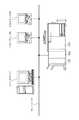
図1は本実施例の検品システムの構成の一例を示す。Example 1
FIG. 1 shows an example of the configuration of an inspection system according to this embodiment.
画像形成装置(印刷装置)101は、各種の入力データを処理して印刷を行い、印刷物を出力する。
検品装置(検査装置)102は、画像形成装置101から出力される印刷物を受け取って印刷物を検査し、検査した印刷物をフィニッシャ103へ搬送する。
フィニッシャ103は、検品装置102で検査された印刷物を受け取り、各種の後処理を行う。An image forming apparatus (printing apparatus) 101 processes various input data, performs printing, and outputs a printed matter.
The inspection device (inspection device) 102 receives the printed matter output from the
The
これらの装置で構成される検品システムにおいて、画像形成装置101はネットワークを介して外部のプリントサーバやクライアントPCへと接続して、データの送受信を行う。また、検品装置102は通信ケーブルを介して画像形成装置101と1対1で接続されており、検品処理の設定情報や検品処理の結果(検品判定情報)などの送受信を行う。またフィニッシャ103も上記とは別の通信ケーブルを介して画像形成装置101と1対1で接続されており、後処理の設定情報などの送受信を行う。また、検品装置102とフィニッシャ103についても別の通信ケーブルを介して相互に接続されており、検品処理の結果(検品判定情報)の送受信が行われている。以上により、本実施例の検品システムは、印刷、検品、フィニッシングまでを一貫して行うインライン検品システムであることが分かる。 In an inspection system composed of these devices, the
[画像形成装置の制御部]
図2は画像形成装置101の制御部の構成を示す。[Control Unit of Image Forming Apparatus]
FIG. 2 shows the configuration of the control unit of the
入力画像処理部201は、紙原稿などをスキャナなどの画像読み取り装置で読み取り、読み取られた画像データを画像処理する。 The input
NIC部202は、ネットワークを利用してプリントサーバやクライアントPCから入力されたPDLデータをRIP部に渡したり、画像形成装置内部の画像や装置情報をネットワーク経由で外部に送信したりする。RIP部は、入力されたPDLデータを解読し、ビットマップ画像データを生成し、主制御部203に送信する。 The NIC
主制御部203は、不図示のCPU、ROM、RAMを有し、これらが協調的に動作することによって制御部として機能している。この主制御部203は、装置内部および装置外部の両方におけるデータ送受信を制御する。また主制御部203は、検品装置102との通信も制御しており、検品装置102で行われた印刷物の検品処理の結果の情報(検品判定情報)を受信し、この検品判定情報に従って、印刷を止める等の制御を行う。また、主制御部203は、受信した画像データをメモリ部204に記憶し、必要に応じてメモリ部204から呼び出して出力画像処理部205へ送信する。 The
出力画像処理部205は、印刷を行うための画像処理を画像データに施し、処理後の画像データをプリンタ部206に送る。また、出力画像処理部205は、プリンタ部206に送った画像データと同じ画像データをリファレンス画像(参照画像)として検品装置102に送信する。なお、必要に応じて、出力画像処理部205は、出力画像処理部205で処理を行う前の画像データをリファレンス画像として検品装置102に送信してもよい。 The output
プリンタ部206は、出力画像処理部205から受信した画像データに基づく印刷処理を行うために、帯電、露光、現像、転写、定着などの電子写真プロセスを制御する。 The
操作部207は、画像形成装置101、検品装置102、フィニッシャ103の動作を制御するためのユーザーが選択可能な情報や、各装置101〜103の状態を示す情報を不図示の操作パネルに表示させる。また、この操作部207は、操作パネルを介したユーザー指示を受け付け、指示情報を主制御部203へ送信する。 The
[画像形成装置101のハードウェア構成]
図3は画像形成装置101のハードウェア構成を示す。[Hardware Configuration of Image Forming Apparatus 101]
FIG. 3 shows a hardware configuration of the
画像形成装置101は、スキャナ部301、レーザ露光部302、感光ドラム303、作像部304、定着部305、給紙/搬送部306、及び、これらを制御する制御部308から構成される。なおこの制御部308の構成は、図2で示されるものであるため説明を省略する。 The
スキャナ部301は、原稿台に置かれた原稿に対して、照明を当てて原稿画像を光学的に読み取り、その像を電気信号に変換して画像データを作成する工程である。 The scanner unit 301 is a step of creating image data by optically reading a document image by illuminating a document placed on a document table and converting the image into an electrical signal.
レーザ露光部302は、上記画像データに応じて変調されたレーザ光などの光線を等角速度で回転する回転多面鏡(ポリゴンミラー)307に入射させ、反射走査光として感光ドラム303に照射する。 The laser exposure unit 302 causes a light beam such as a laser beam modulated according to the image data to enter a rotating polygon mirror (polygon mirror) 307 that rotates at an equal angular velocity, and irradiates the photosensitive drum 303 as reflected scanning light.
作像部304は、感光ドラム303を回転駆動し、帯電器によって帯電させ、上記レーザ露光部によって感光ドラム上に形成された潜像をトナーによって現像する。そのトナー像を用紙に転写し、その際に転写されずに感光ドラム上に残った微小トナーを回収するといった一連の電子写真プロセスの現像ユニット(現像ステーション)を4連持つことで実現している。シアン(C)、マゼンタ(M)、イエロー(Y)、ブラック(K)の順に並べられた4連の現像ユニットは、シアンステーションの作像開始から所定時間経過後に、マゼンタ、イエロー、ブラックの作像動作を順次実行していく。このタイミング制御によって、用紙上に色ずれのない、フルカラートナー像が転写される。本実施例はカラープリンタを想定しているが、これに限定されるものではなく、白黒プリンタの場合にはブラックの現像ユニットのみが搭載される。 The
定着部305は、ローラやベルトの組み合わせによって構成され、ハロゲンヒータなどの熱源を内蔵し、上記作像部によってトナー像が転写された用紙上のトナーを、熱と圧力によって溶解、定着させる。なお、厚紙用紙を印字する際には、紙が厚く、熱の伝導性が低いため、定着部305を通す速度を例えば通常の半分の速度にする必要がある。これに起因して、厚紙用紙の印字の際には定着部305以外の各部の用紙搬送速度も半分になるため、画像形成装置101の印刷速度自体が半分となる。 The
給紙/搬送部306は、用紙カセットやペーパーデッキに代表される用紙収納庫を一つ以上持っており、上記プリンタ制御部の指示に応じて用紙収納庫に収納された複数の用紙の中から一枚を分離し、作像部・定着部へ搬送する。用紙は搬送され、前述の現像ステーションによって、各色のトナー像が転写され、最終的にフルカラートナー像が用紙上に形成される。また、両面印刷を行う場合は、定着部を通過した用紙を再度作像部へ搬送する搬送経路を通るように制御する。 The paper feeding / conveying unit 306 has one or more paper storages represented by paper cassettes or paper decks, and a plurality of papers stored in the paper storages in accordance with instructions from the printer control unit. Separate one sheet and transport it to the image forming unit and fixing unit. The paper is conveyed, and the toner images of the respective colors are transferred by the above-described developing station, and finally a full color toner image is formed on the paper. When performing duplex printing, control is performed so that the sheet that has passed through the fixing unit passes through a conveyance path for conveying the sheet to the image forming unit again.
[フィニッシャの内部構成]
図5は、フィニッシャ103のハードウェア構成の一例を示している。[Internal structure of finisher]
FIG. 5 shows an example of the hardware configuration of the
検品装置102から搬送された印刷物は、フィニッシャ103に入る。フィニッシャ103は、印刷物の排出先としてのエスケープトレイ501及び出力トレイ502と、印刷物の転送パスをどちらのトレイへつなげるかを切り替える転送パス切り替え部505を有する。またフィニッシャ103は、印刷物に対してステープル処理を施すステープラ504を有する。また、フィニッシャ103は、フィニッシャ103の動作全体を統括的に制御する制御部506を有する。この制御部506については、図6を用いて後述する。 The printed material conveyed from the
[フィニッシャのシステムブロック図]
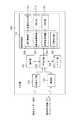
図6はフィニッシャ103の制御部506の構成を示す。[Finisher system block diagram]
FIG. 6 shows a configuration of the
制御部506の主制御部601は、不図示のCPU、ROM、RAMを有し、これらが協調的に動作することによって制御部として機能している。 The
主制御部601は専用の通信線を介して画像形成装置101と通信する。また、主制御部601は専用の通信線を介して検品装置102と通信する。 The
主制御部601は、画像形成装置101から印刷物に対してステープル処理等の後処理を行うのかを指示するフィニッシャ設定情報と、検品装置102から検品判定情報とを受信する。そして主制御部601は、受信した情報に基づいてフィニッシャ103内の各機能を制御する各制御部(602、603)との間で通信を行う。 The
具体的には、主制御部601は、受信したフィニッシャ制御情報に基づいて、印刷物に対してステープル処理を行うのかを制御する情報(ステープラ制御情報)をステープラ制御部603へ送信する。 Specifically, the
また主制御部601は、受信した検品判定情報に基づいて、ステープラ制御情報をステープラ制御部603へ送信し、印刷物の排出先を切り替えるための搬送パス制御情報を搬送パス駆動制御部602へ送信する。例えば、印刷物に画像障害が含まれる旨を示す検品判定情報を受信した場合に、主制御部601は、ステープル処理を行わないようにすべくステープラ制御情報をステープラ制御部603へ送信し、排出先をエスケープトレイ501とすべく搬送パス制御情報を搬送パス駆動制御部602へ送信する。また、印刷物に画像障害が含まれない旨を示す検品判定情報を受信した場合に、主制御部601は、ステープル処理を行うべくステープラ制御情報をステープラ制御部603へ送信し、排出先を出力トレイ502とすべく搬送パス制御情報を搬送パス駆動制御部602へ送信する。 Further, the
搬送パス駆動制御部602は、主制御部601から送信された搬送パス制御情報に基づいて、転送パス切り替え部505の動作を制御することで、印刷物の排出先を制御する。 The transport path drive
ステープラ制御部603は、主制御部601から送信されたステープラ制御情報に基づいて、ステープラ504の動作を制御することで、印刷物に対してステープル処理を行う。 The
[検品装置のハードウェア構成]
図4(a)は検品装置102のハードウェア構成を示している。[Inspection equipment hardware configuration]
FIG. 4A shows the hardware configuration of the
給紙ローラ401は、画像形成装置101から出力された印刷物を引き込む。その後、印刷物は、搬送ベルト402によって搬送されながら、搬送ベルト402上にある検品センサー403で読み取られる。なお、ここでは図示しないが、検品センサー403は両面印刷物にも対応できるように搬送ベルト402の下側からも検品センサーで読み取る構造であってもよい。 The
制御部405は、検品センサー403によって読み取られた画像(スキャン画像)を用いて検品処理を行って、検品処理の結果の情報(検品判定情報)を画像形成装置101およびフィニッシャ103に送信する。制御部405の詳細な構成および検品処理については図7、図9を用いて後述する。また、制御部405は、検品装置102全体の制御も行う。 The
排紙ローラ404は、検品処理後の印刷物をフィニッシャ103へ搬送する。 The paper discharge roller 404 conveys the printed matter after the inspection process to the
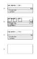
図4(b)は搬送ベルト402の部分を上面視した例を示す図であり、ここで図示されるように、検品センサー403は、搬送されてきた印刷物410の全面の画像をライン毎に読み取るラインセンサーである。 FIG. 4B is a diagram showing an example of a top view of the portion of the
画像読み取り用の照射装置411は、検品センサー403で読み取る際に印刷物に光を照射する画像読み取り用の照射装置である。 The image reading irradiation device 411 is an image reading irradiation device that irradiates a printed material with light when the
斜行検知用の照射装置412は、印刷物410が搬送ベルト402上の搬送中に、搬送方向に対して斜行しているかどうかを読み取るために、搬送される印刷物に対して斜め方向から光を照射する。そして検品センサー403がこの照射による印刷物の端部の影を読み取ることで、斜行は検知される。本実施例では印刷物の端部の影の読み取りは検品センサー403で行われるが、検品センサー403以外の別の読み取りセンサーを用いて影を読み取るようにしてもよい。 The skew detection irradiation device 412 emits light from the oblique direction to the conveyed printed material in order to read whether the printed
[検品装置のシステムブロック図]
図7は検品装置102の制御部405のハードウェアの構成を示す。[System block diagram of inspection equipment]
FIG. 7 shows a hardware configuration of the
主制御部703は、不図示のCPU、ROM、RAMを有し、これらが協調的に動作することによって制御部として機能している。また、主制御部703は、制御部405内の各処理部の動作を統括的に制御することで、検品装置102の全体を制御する。 The
画像入力部701は、検品センサー403で読み取ったスキャン画像を受信する。受信したスキャン画像はメモリ部704に保存される。 The
通信部702は、画像形成装置101およびフィニッシャ103との通信を行う。通信部702は、通信によって、リファレンス画像を受信し、また、検品制御情報の送受信を行う。受信したリファレンス画像と検品制御情報は、メモリ部704に保存される。 A
画像形成装置101との間で送受信される検品制御情報の1つは検品判定情報であり、また検品制御情報の1つは、印刷ジョブ情報・印刷部数情報・ページ順情報などスキャン画像とリファレンス画像との対応を取るための同期情報である。同期情報は、両面印刷や複数部数印刷のために、スキャン画像と、それを印刷するのに利用されたリファレンス画像を検品装置102で受信する順番が異なる場合のために必要とされる。また動機情報は、1枚のリファレンス画像が複数のスキャン画像と対応している場合があるために必要とされる。 One of the inspection control information transmitted / received to / from the
フィニッシャ103との間で送受信される検品制御情報は、検品判定情報である。 The inspection control information transmitted / received to / from the
操作部705は、検品処理の結果を不図示の操作パネルに表示させる。 The
検品処理部713は、リファレンス画像およびスキャン画像を用いて印刷物に対して検品処理を行う。検品処理部713の詳細については後述する。 The
[検品処理部の構成]
検品処理部713の詳細な構成について説明をする。[Configuration of inspection processing section]
A detailed configuration of the
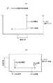
斜行検知部706は、印刷物の斜行を検知し、斜行角度の情報を生成する。図8を用いて斜行検知についてさらに説明する。 The
前述したように、照射装置412の光の照射によって生じた印刷物410の端部の影(端部影)801は検品センサー403で読み取られる。この読み取られた影は影画像として斜行検知部706に送信される。 As described above, the
斜行検知部706は、影画像に対して二値化処理及びエッジ検出処理等を行うことで、影画像の斜行を検出する。例えば、影画像に対して二値化処理及びエッジ検出処理等を行った後の画像が図8(b)のようになっていた場合、斜行検知部706は、まず基準座標811を決定し、次に端部影801上に始点座標812と終点座標813を決定する。そして斜行検知部706は、座標812、813の基準座標811からの相対座標を求める。 The
ここでは基準座標811を座標(0、0)とした場合に、始点座標812は座標(300、245)、終点座標813は座標(235、3885)となり、斜行検知部706は、座標812、813それぞれの相対座標から端部影801の傾きθ(deg)を求める。するとこの場合のθ(deg)は、 Here, when the reference coordinate 811 is the coordinate (0, 0), the start point coordinate 812 is the coordinate (300, 245), the end point coordinate 813 is the coordinate (235, 3885), and the

として求められる。したがって、斜行検知部706は、印刷物410が搬送方向に対して時計回り方向に1.023度斜行していると検出する。なお、印刷物の斜行角度が印刷物ごとに変わらず、一定の角度であるような場合には、最初の1枚の印刷物の斜行角度を次ページ以降の印刷物の斜行角度としてもよい。もしくは、影画像の探索の開始点を、前ページの印刷物の斜行角度によって決めてもよい。このように、斜行検知部706は、印刷物の斜行を検知し、斜行角度の情報を生成する。また斜行検知部706は、生成した斜行角度の情報をメモリ部704に保存する。 As required. Therefore, the
画質差調整部707は、色空間の違いや全体的な明度の違いなどといった、スキャン画像とリファレンス画像の間の画質の差異(画質差)を調整する。 The image quality
この画質差は、印刷前の画像処理・画像形成装置特性・スキャナ特性の影響、あるいは画像形式の違いにより生じるものであって、画像障害の有無にかかわらず生じる。なお印刷前の画像処理とは、色変換処理やガンマ処理やハーフトーン処理などである。また画像形成装置特性とは、色再現性やドットゲインやガンマ特性などである。またスキャナ特性とは、色再現性やS/NやスキャナMTFなどである。また、画像形式の違いとは、両画像間の1画素のbit数が異なることである。画質差調整部707は、これらの影響を除去し、画像障害がなければスキャン画像とリファレンス画像とが画質差のない同等のものとなるように、補正処理を両方またはリファレンス画像のみに施す。 This difference in image quality is caused by the influence of image processing before printing, the characteristics of the image forming apparatus, the scanner characteristics, or the difference in image format, and occurs regardless of the presence or absence of an image failure. The image processing before printing includes color conversion processing, gamma processing, halftone processing, and the like. The image forming apparatus characteristics include color reproducibility, dot gain, and gamma characteristics. The scanner characteristics include color reproducibility, S / N, scanner MTF, and the like. The difference in image format is that the number of bits per pixel between the two images is different. The image quality
補正処理は、色変換処理・ガンマ補正処理・フィルタ処理(網点の平滑化処理やエッジなまりの調整処理)・bit幅調整処理である。リファレンス画像のみに施す場合は、シミュレーションによりリファレンス画像からスキャン画像と同等の画像を作ることとなるため、画像障害が生じていない画像形成装置101および検品センサー403の特性をシミュレーションすることと等価となる。 The correction processing includes color conversion processing, gamma correction processing, filter processing (halftone dot smoothing processing and edge rounding adjustment processing), and bit width adjustment processing. When applied only to the reference image, an image equivalent to the scanned image is created from the reference image by simulation, which is equivalent to simulating the characteristics of the
解像度変換部708は、スキャン画像やリファレンス画像の解像度の変換を行う。スキャン画像とリファレンス画像は、制御部405に入力された時点で解像度が異なっている場合がある。また、後述の位置合わせ処理の精度を制御するうえで、画像の解像度を変える場合がある。そのような場合に、解像度変換処理が行われる。 A
例えば、スキャン画像が主走査600dpi/副走査300dpiであり、リファレンス画像が主走査1200dpi/副走査1200dpiであったとする。検品処理部713で必要とされる解像度が主走査・副走査ともに300dpiであった場合には、それぞれの画像を縮小変倍して、両方の画像を主走査・副走査ともに300dpiの画像とする。変倍の方法は、計算量と必要精度を勘案して、公知の方法を利用すればよい。例えば、SINC関数を利用した変倍を行えば、計算量は多いが、高精度の変倍結果を得ることができる。最近傍法を利用した変倍を行えば、計算量は少ないが、低精度の変倍結果を得ることになる。 For example, assume that the scanned image is main scanning 600 dpi / sub scanning 300 dpi, and the reference image is main scanning 1200 dpi / sub scanning 1200 dpi. If the resolution required by the
画像変形部709は、スキャン画像やリファレンス画像の画像変形処理を行う。スキャン画像とリファレンス画像の間には、印刷時の用紙の伸縮や斜行、スキャン時の斜行により、幾何的な相違が存在する。画像変形部709は、斜行検知部706からの斜行角度の情報や後述する位置合わせ部710からの位置合わせ情報を用いて、画像の幾何変形を行うことにより、その幾何的な相違を補正する。 An
例えば、幾何的な相違は、線型変換(回転、拡大縮小、剪断)と平行移動である。この幾何的な相違は、アフィン変換として表現可能であり、アフィン変換パラメータを斜行検知部706や位置合わせ部710から得ることにより補正を行うことが可能となる。 For example, geometrical differences are linear transformation (rotation, scaling, shearing) and translation. This geometrical difference can be expressed as an affine transformation, and can be corrected by obtaining the affine transformation parameters from the
この画像変形部709は、画像の幾何変形処理を行われたスキャン画像およびリファレンス画像を照合部711へ送信する。 The
位置合わせ部710、照合部711、判定部712については以下、順に説明する。 The alignment unit 710, the
[位置合わせ部710]
位置合わせ部710は、スキャン画像とリファレンス画像の間の位置合わせ処理を行い、前述の画像変形部709での画像の幾何変形処理に用いられるアフィン変換パラメータ(位置合わせ情報)を算出する。なお、位置合わせ部710は同解像度のスキャン画像とリファレンス画像に対して位置合わせ処理を行うこととする。なお入力解像度が高いほど、位置合わせの精度が向上するが、計算量は大きくなる。[Alignment unit 710]
The alignment unit 710 performs alignment processing between the scanned image and the reference image, and calculates affine transformation parameters (alignment information) used for the geometric deformation processing of the image by the
位置合わせ手法としては、様々な位置合わせ手法が考えられるが、本実施例は、計算量を減らすために、画像全面ではなく、画像の一部である矩形領域(以下パッチあるいはパッチ画像と呼ぶ)の画像情報および位置情報を利用して、画像全面の位置合わせを行う手法を利用する。本実施例の位置合わせは、位置合わせ用パッチの選択・パッチごとの位置合わせ・アフィン変換パラメータの算出の3つのステップからなる。それぞれのステップについて説明をする。 Various alignment methods can be considered as the alignment method. In this embodiment, in order to reduce the amount of calculation, a rectangular area that is a part of the image, not the entire image (hereinafter referred to as a patch or a patch image) is used. A method for aligning the entire image using the image information and position information of the image is used. The alignment in this embodiment includes three steps: selection of alignment patches, alignment for each patch, and calculation of affine transformation parameters. Each step will be described.
[位置合わせ部710におけるパッチの選択]
まず、位置合わせ用パッチの選択について説明する。[Selection of Patch in Positioning Unit 710]
First, selection of the alignment patch will be described.
位置合わせ部710は、位置合わせ用パッチの選択において、リファレンス画像から、位置合わせ処理に適した複数個のパッチの選択を行う。位置合わせ処理に適したパッチとして、パッチ画像内のコーナー特徴量が大きいパッチが考えられる。なおコーナー特徴とは、ある局所近傍で方向の異なる2つの際立ったエッジが存在するような特徴(2つのエッジの交点)である。コーナー特徴量は、このエッジ特徴の強さを表す特徴量である。 In the selection of the alignment patch, the alignment unit 710 selects a plurality of patches suitable for the alignment process from the reference image. As a patch suitable for the alignment processing, a patch having a large corner feature amount in the patch image can be considered. Note that a corner feature is a feature (an intersection of two edges) in which there are two distinct edges in different directions near a certain local area. The corner feature amount is a feature amount representing the strength of the edge feature.
なおコーナー特徴の検出方法には、「エッジ特徴」のモデル化の違いにもとづき、様々な手法が考案されている。コーナー特徴量を計算する方法の1つとしては、Harrisのコーナー検出法と呼ばれる公知の方法がある。Harrisのコーナー検出法は水平方向の微分画像(水平方向のエッジ特徴量画像)と、垂直方向の微分画像(垂直方向のエッジ特徴量画像)から、コーナー特徴量画像を計算する。このコーナー特徴量画像は、コーナー特徴を構成する2つのエッジのうち弱い方のエッジ量を表現した画像となっている。コーナー特徴は2つのエッジのどちらも強いエッジであるはずなので、相対的に弱い方のエッジであっても強いエッジ量を持っているどうかでコーナー特徴量の大きさを表現している。 Various methods for detecting corner features have been devised based on the modeling of “edge features”. One of the methods for calculating the corner feature amount is a known method called the Harris corner detection method. The Harris corner detection method calculates a corner feature value image from a horizontal differential image (horizontal edge feature value image) and a vertical differential image (vertical edge feature value image). This corner feature amount image is an image expressing the weaker edge amount of two edges constituting the corner feature. Since both corners should be strong edges, the size of the corner feature is expressed by whether or not the relatively weak edge has a strong edge amount.
位置合わせ部710は、リファレンス画像からコーナー特徴量画像を計算し、所定の閾値以上である大きなコーナー特徴量を持つパッチを、位置合わせに適したパッチとして選択する。 The alignment unit 710 calculates a corner feature amount image from the reference image, and selects a patch having a large corner feature amount that is equal to or greater than a predetermined threshold as a patch suitable for the alignment.
なお単純にコーナー特徴量が大きい領域を順番にパッチとして選択すると、画像内の一部分の領域からのみパッチが選択される場合がある。このようなパッチから求められたアフィン変換パラメータは画像の局所領域の幾何変形を表していることになるので、パッチを局所領域のみから選択することは、画像全体の位置合わせをする上で望ましくない。そこで、パッチを選択する際には、単にコーナー特徴量の大きさではなく、選択されるパッチが画像内に分散していることも考慮する。具体的には、位置合わせ部710は、あるパッチのコーナー特徴量が画像内全体の中での値が大きくなかったとしても、その値が、画像の局所領域内のパッチの特徴量の平均から所定の閾値以上であれば、位置合わせ処理に用いられるパッチとして選択する。こうすることにより、リファレンス画像内に位置合わせ処理に用いられるパッチを分散配置させることができる。 Note that if a region having a large corner feature is simply selected as a patch in order, the patch may be selected only from a partial region in the image. Since the affine transformation parameter obtained from such a patch represents the geometric deformation of the local region of the image, selecting the patch from only the local region is not desirable in aligning the entire image. . Therefore, when selecting a patch, it is considered not only the size of the corner feature amount but also that the selected patch is dispersed in the image. Specifically, even if the corner feature value of a certain patch does not have a large value in the entire image, the alignment unit 710 calculates the value from the average of the feature values of the patches in the local region of the image. If it is greater than or equal to a predetermined threshold, it is selected as a patch used for the alignment process. In this way, patches used for the alignment process can be distributed in the reference image.
なお位置合わせ部710は、パッチ選択を選択パラメータに基づいて行う。この選択パラメータは、選択されるパッチの大きさ、パッチの個数(または密度)を制御するパラメータである。パッチが大きくなり、パッチの個数が多くなると、位置合わせの精度が向上する一方、計算量は大きくなる。すなわち、位置合わせ部710の行う位置合わせ処理の精度は、選択パラメータによって制御されることになる。 The alignment unit 710 performs patch selection based on the selection parameter. This selection parameter is a parameter that controls the size of the selected patch and the number (or density) of patches. As the number of patches increases and the number of patches increases, the accuracy of alignment improves, while the amount of calculation increases. That is, the accuracy of the alignment process performed by the alignment unit 710 is controlled by the selection parameter.
パッチ選択の例を、図10を用いて説明する。 An example of patch selection will be described with reference to FIG.
図10(a)はリファレンス画像を示し、図10(b)はこのリファレンス画像の水平方向のエッジ特徴量の強度を示す。同様に、図10(c)は垂直方向のエッジ特徴量の強度を示す。図10(b)と図10(c)に示されるエッジ特徴量の強度から、コーナー特徴量を計算したものが、図10(d)となる。なお、図10(b)、(c)、(d)において、各特徴量が大きいほど、より白く表示されている。図10(d)をみると、太文字領域と、罫線の交点が大きなコーナー特徴量をもつ領域となっていることが分かる。 FIG. 10A shows a reference image, and FIG. 10B shows the strength of the edge feature amount in the horizontal direction of the reference image. Similarly, FIG. 10C shows the strength of the edge feature amount in the vertical direction. FIG. 10D shows a corner feature amount calculated from the edge feature amount intensities shown in FIGS. 10B and 10C. In FIGS. 10B, 10 </ b> C, and 10 </ b> D, the larger the feature amount, the more white the image is displayed. As can be seen from FIG. 10D, the intersection of the bold character area and the ruled line is an area having a large corner feature.
図10(e)は、図10(d)のコーナー特徴量の情報を元に、位置合わせ処理に用いられるパッチを選択したもので、白い点線で囲まれている領域が、選択されたパッチの領域を示している。単純にコーナー特徴量が大きい領域だけをパッチとして選択するのでは、左上と左下の領域でしかパッチが選択されない可能性があるが、前述したように、パッチの分散具合も考慮することにより、図10(e)のようにパッチが選択される。 FIG. 10E shows a patch selected for registration processing based on the corner feature information shown in FIG. 10D. An area surrounded by a white dotted line indicates the selected patch. Indicates the area. If only a region with a large corner feature is selected as a patch, there is a possibility that the patch is selected only in the upper left and lower left regions. The patch is selected as in 10 (e).
図10(f)は、図10(e)で選択されたパッチをリファレンス画像上に示したもので、黒い点線で囲まれている領域が位置合わせ処理に用いられるパッチである。 FIG. 10F shows the patch selected in FIG. 10E on the reference image, and a region surrounded by a black dotted line is a patch used for the alignment process.
[位置合わせ部710におけるパッチごとの位置合わせ]
次にパッチごとの位置合わせについて説明をする。[Alignment for each patch in the alignment unit 710]
Next, positioning for each patch will be described.
ここで位置合わせ部710は、前段で選択したリファレンス画像内の位置合わせ用パッチと、それに対応するスキャン画像内のパッチとの間で位置合わせ処理を行っていく。 Here, the alignment unit 710 performs alignment processing between the alignment patch in the reference image selected in the previous stage and the corresponding patch in the scan image.
図11は、両画像におけるパッチ間の位置の対応関係について説明する図である。 FIG. 11 is a diagram for explaining the correspondence between the positions of patches in both images.
図11(a)は、リファレンス画像内の位置合わせ用パッチを黒の点線枠で示したものである。 FIG. 11A shows the alignment patch in the reference image indicated by a black dotted frame.
図11(b)は、リファレンス画像内の位置合わせ用パッチ(リファレンスパッチ)と対応する位置にある、スキャン画像内の領域(スキャンパッチ)を黒の点線枠で示したものである。 FIG. 11B shows a region (scan patch) in the scan image at a position corresponding to the alignment patch (reference patch) in the reference image by a black dotted frame.
これらリファレンスパッチとスキャンパッチの位置の対応関係について図11(c)、(d)を用いて説明する。例えば、図11(c)に示すリファレンスパッチに対応するスキャンパッチは図11(d)に示されるものである。これら2パッチ間の位置合わせ処理の結果として、得られる情報は2種類ある。1つ目は、i番目(i=1〜N、Nはパッチ数)のリファレンスパッチの中心座標(refpX_i,refpY_i)である。2つ目は、そのリファレンスパッチの中心座標における画像の、スキャンパッチ内での位置を表す座標(scanpX_i,scanpY_i)である。 The correspondence between the positions of these reference patches and scan patches will be described with reference to FIGS. For example, a scan patch corresponding to the reference patch shown in FIG. 11C is shown in FIG. There are two types of information obtained as a result of the alignment process between these two patches. The first is the center coordinates (refpX_i, refpY_i) of the i-th reference patch (i = 1 to N, N is the number of patches). The second is coordinates (scanx_i, scanY_i) representing the position in the scan patch of the image at the center coordinates of the reference patch.
位置合わせ手法は、座標(refpX_i、refpY_i)および(scanpX_i、scanpY_i)の位置の対応関係が得られるようなシフト量推定方法であれば、どのような手法であってもよい。例えば、FFT(高速フーリエ変換)による方法がある。この方法では、リファレンスパッチおよびスキャンパッチのパッチ対に対してFFTを行い、周波数空間上でのこれら2パッチ間の相関をとることで、シフト量を推定する。 The positioning method may be any method as long as it is a shift amount estimation method that can obtain a correspondence relationship between the coordinates (refpX_i, refpY_i) and (scanpX_i, scanY_i). For example, there is a method by FFT (Fast Fourier Transform). In this method, the amount of shift is estimated by performing FFT on the patch pair of the reference patch and the scan patch, and taking the correlation between these two patches in the frequency space.
[位置合わせ部710におけるアフィン変換パラメータの算出]
アフィン変換パラメータの算出について説明をする。アフィン変換は、下記の変換式で表現される座標変換方法である。[Calculation of Affine Transformation Parameters in Positioning Unit 710]
The calculation of affine transformation parameters will be described. Affine transformation is a coordinate transformation method expressed by the following transformation formula.
上記の式で、アフィン変換パラメータは、a、b、c、d、e、fの6種類である。ここで、(x、y)は(refpX_i、refpY_i)のことであり、(x’、y’)は(scanpX_i、scanpY_i)のことである。N個のパッチ対から得られる、N個のこの変換式を用いて、位置合わせ部710は、アフィン変換パラメータを算出する。例えば、最小二乗法を用いて、アフィン変換パラメータが求められる。 In the above formula, there are six types of affine transformation parameters: a, b, c, d, e, and f. Here, (x, y) is (refpX_i, refpY_i), and (x ′, y ′) is (scanpX_i, scanY_i). Using the N conversion equations obtained from the N patch pairs, the alignment unit 710 calculates an affine transformation parameter. For example, an affine transformation parameter is obtained using a least square method.
そして位置合わせ部710は、求めたアフィン変換パラメータを位置合わせ情報として画像変形部709へ送信する。 Then, the alignment unit 710 transmits the obtained affine transformation parameters to the
[照合部711]
照合部711は、画像変形部709によって画像の幾何変形処理が行われた後のスキャン画像およびリファレンス画像を受信し、これら両画像間の照合を行う。[Verification unit 711]
The
照合部711は、まず、リファレンス画像とスキャン画像の差分画像を生成する。差分画像は、例えば、
差分画像DIF(x、y) =
DIS(リファレンス画像REF(x、y)−スキャン画像SCAN(x、y))
のようにして計算される。ここで、(x、y)は座標で、DIS(・)は画素値間の距離を求める関数である。DIS(・)は、両画像がグレースケール画像であれば、画素値の差の絶対値を求める関数でもよいし、ガンマ補正を考慮した差の絶対値を求める関数であってもよい。カラー画像の場合は、色差を求める関数とすれば良い。The
Difference image DIF (x, y) =
DIS (reference image REF (x, y) -scan image SCAN (x, y))
It is calculated as follows. Here, (x, y) is a coordinate, and DIS (•) is a function for obtaining a distance between pixel values. DIS (•) may be a function for obtaining an absolute value of a difference between pixel values or a function for obtaining an absolute value of a difference in consideration of gamma correction if both images are grayscale images. In the case of a color image, a function for obtaining a color difference may be used.
次に、照合部711は、得られた差分画像の中で所定の閾値以下の画素値を持つ領域の画素値をゼロ(0)として、修正差分画像を生成する。この所定の閾値は、画質差調整部707の行う画像処理では吸収しきれない画質差をもつ画素が画像障害に該当しないような値に設定される。 Next, the
次に、照合部711は、画素値が非ゼロ(非0)である画素を連結して、画素値が非ゼロである画素群の画素塊を生成する。この画素塊はリファレンス画像およびスキャン画像の両画像間で差異のある、まとまった領域を示している。 Next, the
そして、照合部711は、画像内すべての画素塊のそれぞれについて、画像特徴量を求める。この画像特徴量は、差異のある領域として検出された画素塊の領域における、リファレンス画像およびスキャン画像の両画像間の差異の程度を示している。 Then, the
本実施例では画像特徴量の一例として、平均差分値と面積を用いる。この面積とは、画素塊の領域内の画素数の総和のことであり、平均差分値とは、画素塊の領域内の画素値の総和を面積で割ったものである。すなわち、平均差分値や面積が大きければ大きいほど、両画像間の差異は大きいことになる。なお画像特徴量としてはほかに、分散値などを用いてもよい。 In this embodiment, an average difference value and an area are used as an example of the image feature amount. This area is the sum of the number of pixels in the pixel block region, and the average difference value is the sum of the pixel values in the pixel block region divided by the area. That is, the larger the average difference value or area, the greater the difference between the two images. In addition, a variance value or the like may be used as the image feature amount.
また、この画像特徴量は、画素塊が、更なる高精度の位置合わせ処理を行った後に改めて照合部711によって照合されるべき領域であるのかを判定するために、判定部712で用いられる。 Further, the image feature amount is used by the
照合部711は、修正差分画像と、画素塊に関する情報(画素塊それぞれの位置情報と画像特徴量)とを、照合結果として判定部712に送信する。 The
以上説明したように照合部711は、修正差分画像および画素塊に関する情報を生成することによって、リファレンス画像およびスキャン画像の両画像間の差異のある領域を検出する差異検出手段として機能している。 As described above, the
[判定部712]
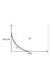
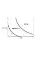
判定部712は、照合部711から受信した照合結果を用いて、画像障害候補の有無を判定する(判定処理)。具体的には、判定部712は、それぞれの画素塊について、画像特徴量を評価して、その画素塊が画像障害候補であるかの判定を行う。例えば、本実施例の判定部712は、画像特徴量が面積と平均差分値で有った場合、図12のような判定基準を用いて画素塊が画像障害候補かどうかの判定を行う。[Determining unit 712]
The
図12は、横軸を画素塊の面積、縦軸を画素塊の平均差分値とした特徴量空間を示す図であって、この特徴量空間をOK領域およびNG領域に二分する境界線のグラフ(第1の判定基準)を有する。なお、図12のOK領域とは画素塊が画像障害候補ではないことを示す領域であり、図12のNG領域とは画素塊が画像障害候補とみなされる領域である。このグラフの情報(第1の判定基準の情報ともいう)は予めメモリ部704に記憶されており、判定部712は、判定処理を行う際にこのグラフの情報を、主制御部703を介してメモリ部704から取得する。 FIG. 12 is a diagram illustrating a feature amount space in which the horizontal axis is the area of the pixel block and the vertical axis is the average difference value of the pixel block, and is a graph of a boundary line that bisects the feature amount space into an OK region and an NG region. (First criterion). The OK area in FIG. 12 is an area indicating that the pixel block is not an image defect candidate, and the NG area in FIG. 12 is an area in which the pixel block is regarded as an image defect candidate. Information on this graph (also referred to as first determination criterion information) is stored in the
なお、画像特徴量が3つ以上ある場合には、画像特徴量が構成する特徴空間上で、NG領域と、それ以外を区別する平面パラメータ(もしくは[画像特徴量の次元−1次元]の超平面のパラメータ)の情報が、主制御部703を介して、メモリ部704から判定部712に読み出される。 If there are three or more image feature amounts, the plane parameter (or [dimension of image feature amount minus one dimension]) that distinguishes the NG region from the other in the feature space formed by the image feature amount is used. Information on the plane parameters) is read from the
判定部712は、それぞれの画素塊について画素塊の画像特徴量を図12の特徴量空間にプロットし、画素塊の画像特徴量が図12のOK領域とNG領域とのどちらの領域に含まれるかを判定する。すなわち、判定部712は、画素塊の画像特徴量が第1の判定基準であるグラフ(図12)の示す境界上の値以上(第1の判定基準の値以上)であるか否かを判定している。画素塊の画像特徴量が図12のグラフで示された値以上である場合、画素塊は画像障害候補とみなされ、画素塊の画像特徴量が図12のグラフで示された閾値未満である場合、画素塊は画像障害候補でないとみなされる。 The
判定の結果、画像障害候補とみなされなかった画素塊の領域について、判定部712は、その画素塊の修正差分画像における画素値を0とする。このようにしてすべての画素塊についての判定処理を終了すると、判定部712は、画像障害候補とみなされた領域だけが非ゼロとなっている画像を、判定結果画像として得る。 As a result of the determination, the
判定部712は、この判定結果画像と、判定結果画像上に残っている画素塊に関する情報を出力する。 The
以上説明したように判定部712は、画素塊の画像特徴量が示す、リファレンス画像およびスキャン画像の両画像間の差異の程度に基づいて、画像障害候補となる領域を検出する候補領域検出手段として機能している。 As described above, the
[検品装置の制御フロー]
以下において、本実施例の検品処理に関して図9を用いて説明する。図9は、本実施例の検品処理の一連の処理フローを示したフローチャートである。これらの処理を実行するためのコンピュータプログラムはメモリ部704に記憶されている。主制御部703はこのコンピュータプログラムをメモリ部704から読み出して実行することで、図9のフローチャートの一連の処理が実行されるように、制御部405内の各処理部を制御する。以下で説明する処理は、主制御部703によって、各処理部が統括的に制御されることで実現される。また、各処理部で処理された結果はメモリ部704に記憶され、後続の処理で利用される。[Control flow of inspection equipment]
In the following, the inspection process of the present embodiment will be described with reference to FIG. FIG. 9 is a flowchart showing a series of processing flows of the inspection processing of the present embodiment. A computer program for executing these processes is stored in the
ステップS901では、斜行検知部706および画質差調整部707は、検品処理の前処理を行う。まず、主制御部703は、メモリ部704に保存されている、画像形成装置101から受信した検品制御情報を用いて、処理するべきスキャン画像とリファレンス画像との画像ペアを選択する。 In step S901, the
続いて、斜行検知部706は、スキャン画像を処理し、スキャン画像の斜行角度の情報を生成する。そして、その斜行角度の情報にもとづいて、画像変形部709はスキャン画像の補正処理を行う。これと並行して、画質差調整部707はリファレンス画像を処理して、検品処理に適した画像とする。 Subsequently, the
ステップS902において、S901で得られたスキャン画像とリファレンス画像との低精度の位置合わせが行われる。位置合わせの精度と計算量はトレードオフの関係がある。本ステップでは、計算量を抑えることを優先し、低精度の位置合わせを実施する。位置合わせで考慮すべきパラメータは、解像度・パッチサイズ・パッチ密度の3種類である。 In step S902, low-accuracy alignment between the scan image obtained in S901 and the reference image is performed. There is a trade-off between alignment accuracy and computational complexity. In this step, priority is given to reducing the amount of calculation, and low-precision alignment is performed. There are three types of parameters to be considered in alignment: resolution, patch size, and patch density.
まず、解像度変換部708は、スキャン画像とリファレンス画像とを低精度位置合わせ用の所定の解像度(例えば、低解像度の150dpi×150dpi)の画像に変換する。 First, the
そして、位置合わせ部710は、所定の解像度となったスキャン画像およびリファレンス画像に対して、低精度位置合わせ用の選択パラメータに基づいて位置合わせ処理を行い、アフィン変換パラメータを得る。この低精度位置合わせ用の選択パラメータとは、例えば、パッチサイズを小さいパッチとなる64画素×64画素とし、パッチ密度を300画素×300画素ごとに1つのパッチが選ばれるような疎な密度としたものである。 Then, the alignment unit 710 performs alignment processing on the scan image and the reference image having a predetermined resolution based on the selection parameter for low-precision alignment, and obtains an affine transformation parameter. The selection parameter for this low-accuracy alignment is, for example, a sparse density such that the patch size is 64 pixels × 64 pixels, which is a small patch, and one patch is selected for every 300 pixels × 300 pixels. It is what.
図13(a)はリファレンス画像の例である。図13(b)は、図13(a)のリファレンス画像上に低精度位置合わせ用のパッチを黒点線で示したものである。低精度位置合わせであるため、パッチサイズは小さく、密度は疎になっている。 FIG. 13A shows an example of a reference image. FIG. 13B shows a patch for low-precision positioning indicated by a black dotted line on the reference image shown in FIG. Due to the low precision alignment, the patch size is small and the density is sparse.
そして画像変形部709は、位置合わせ部710から得たアフィン変換パラメータを用いて、リファレンス画像の補正処理を行い、座標系をスキャン画像と同じにし、照合に利用可能な画像とする。 The
すなわち、ステップS902において、解像度変換部708、位置合わせ部710、画像変形部709は、リファレンス画像とスキャン画像との位置合わせを所定の精度で行う位置合わせ手段として機能していることになる。 That is, in step S902, the
ステップS903において、S902で得られたスキャン画像とリファレンス画像を用いた照合/判定処理が行われる。まず、照合部711は、スキャン画像とリファレンス画像の照合処理を行う。 In step S903, a collation / determination process using the scan image and the reference image obtained in S902 is performed. First, the
そして、照合部711の処理結果を用いて、判定部712は判定処理を行う。判定部712の判定処理には、あらかじめ操作部705から設定される所定の判定基準(図12参照)が用いられる。 Then, using the processing result of the
判定処理の結果として出力された判定結果画像の画像塊は、最終結果ではないので、画像障害候補の画像塊であると考える。例えば、図13(a)がリファレンス画像で、図13(c)がスキャン画像であった場合に、判定処理の結果、画像障害候補とみなされた画像塊は判定結果画像である図13(d)の画像塊1302と画像塊1303となる。図13(c)の1301は、印刷中に生じた画像障害である。画像障害1301は、判定の結果、画像塊1302として、画像障害候補として判定をされたことになる。一方、画像塊1303は、位置合わせ精度により差分画像作成の際に差分が生じ、図13(c)の罫線が画像障害候補として誤認識される。 Since the image block of the determination result image output as a result of the determination process is not the final result, it is considered to be an image block of the image failure candidate. For example, when FIG. 13A is a reference image and FIG. 13C is a scanned image, an image block that is regarded as an image failure candidate as a result of the determination process is a determination result image. ) Image block 1302 and
ステップS904において、主制御部703は、判定結果画像に未処理の画像障害候補の画像塊があるかどうかを判定する。画像障害候補が1つもなかったり、すべての画像障害候補についての処理が終了したりしている場合には、ステップS913に進む。未処理の画障害候補があった場合にはステップS905に進む。 In step S <b> 904, the
ステップS905において、判定部712は、未処理の画像障害候補の画像塊の1つをステップS906〜ステップS912で処理対象の画像塊として選択する。 In step S905, the
ステップS906において、判定部712は、ステップS905で選択した画素塊の領域が高精度位置合わせすべき領域かどうかの判定を行う。 In step S <b> 906, the
ここで、ステップS906の処理について詳しく説明する。 Here, the process of step S906 will be described in detail.
ステップS905で選択された画素塊の中には、ステップS902における位置合わせ処理が低精度だったために検出されたものも含まれることがある。 The pixel block selected in step S905 may include a pixel block detected because the alignment process in step S902 has low accuracy.
誤判定が生じる可能性があるのは、リファレンス画像におけるエッジの近傍領域である。エッジの近傍領域では画素値が急激に変化しているため、位置合わせの精度が低いと、スキャン画像とリファレンス画像との照合において、大きな差分が検出されやすくなり、その箇所は画像障害候補として判定されてしまう。 An erroneous determination may occur in a region near the edge in the reference image. Since pixel values change rapidly in the vicinity of the edge, if the alignment accuracy is low, a large difference is likely to be detected in the comparison between the scanned image and the reference image, and the location is determined as an image failure candidate. It will be.
言い換えると、画像障害候補として判定された画素塊の近傍領域(周辺領域)にエッジが存在する場合、その画素塊は位置合わせ精度の低さのせいで画像障害候補として検出された可能性がある。また、このような画像障害候補の領域に精度の高い位置合わせを行って照合/判定処理を行えば、この画素塊は画像障害ではないと正しく判定される可能性がある。 In other words, when an edge exists in the vicinity area (peripheral area) of a pixel block determined as an image failure candidate, the pixel block may be detected as an image failure candidate because of poor alignment accuracy. . Further, if collation / determination processing is performed by performing high-precision alignment on such image failure candidate regions, there is a possibility that this pixel block is correctly determined not to be an image failure.
そこで、ステップS906では、判定部712は、処理対象の画素塊の領域は高精度位置合わせすべき領域かを判定する。具体的には、判定部712は、リファレンス画像において、画素塊の領域の位置に対応する位置の周辺領域にエッジ(特徴点)が存在するかを判定する。 Therefore, in step S906, the
そして、エッジが存在すると判定される場合、判定部712は、画素塊の領域は高精度の位置合わせが行われる領域であると判定し、処理をステップS908に進める。一方、エッジが存在しないと判定される場合、判定部712は、画素塊の領域は画像障害の領域であると判定し、処理をステップS907に進める。 If it is determined that an edge is present, the
なお、画素塊の周辺領域とは、画素塊の領域を含む画素塊の領域の周辺からN画素の距離以内の領域である。Nは低精度位置合わせの精度に依存して決まる値である。本実施例では、Nは2〜3画素とする。また、この画素塊の周辺領域のことを画像障害候補の領域と呼ぶこともある。 The peripheral region of the pixel block is a region within a distance of N pixels from the periphery of the pixel block region including the pixel block region. N is a value determined depending on the accuracy of the low-precision alignment. In this embodiment, N is 2 to 3 pixels. In addition, the peripheral area of the pixel block may be referred to as an image failure candidate area.
この処理について図13を用いて説明する。図13(e)は、リファレンス画像である図13(a)の水平方向微分画像(図10(b))と垂直方向微分画像(図10(c))を足し合わせたエッジ画像である。より白い部分がエッジの強い部分で、黒い部分がエッジの存在しない部分である。図13(e)において、画像塊1302の周辺領域に対応する領域1304にはエッジは存在しない。そのため、この画像塊1302の領域は高精度位置合わせが行われない領域である判定される。また図13(e)において、画像塊1303の周辺領域に対応する領域1305にはエッジが存在する。そのため、この画像塊1303の領域は高精度位置合わせが行われる領域であると判定される。 This process will be described with reference to FIG. FIG. 13E is an edge image obtained by adding the horizontal direction differential image (FIG. 10B) and the vertical direction differential image (FIG. 10C) of FIG. The whiter part is a part with a strong edge, and the black part is a part without an edge. In FIG. 13E, no edge exists in the
フローチャートの説明に戻る。 Return to the description of the flowchart.
ステップS907において、判定部712は、ステップS904で選択された処理対象の画像塊の領域を画像障害領域とする。そして、判定部712は、画像障害とされたステップS903から出力された判定結果画像上の画素塊を最終判定結果画像に複製する。最終判定結果画像は、何も追加される前は、すべての画素値が0の画像であり、最終的な判定結果を表現するための画像となる。ここでの処理について図13を用いて説明すると、図13(d)の画素塊1302が最終判定結果画像に複製されて、画素塊1306を有する図13(f)のような最終判定結果画像が生成される。なお、判定部712は、最終判定結果画像に複製した画素塊に関する情報をメモリ部704に保存する。そして、処理はステップS912に進む。 In step S907, the
ステップS908において、解像度変換部708、位置合わせ部710、画像変形部709は、高精度の位置合わせを行う。この高精度の位置合わせは、ステップS902で行われる位置合わせよりも位置合わせの精度が高い。 In step S908, the
解像度変換部708は、まず、リファレンス画像とスキャン画像から、画像障害候補の画素塊とその周辺領域の部分を包含する部分画像(部分リファレンス画像と部分スキャン画像)を切り出す。この部分画像の大きさは後段の高精度位置合わせのためのパッチが十分に選べることが見込める大きさであればどのようなサイズであってもよいが、計算量を抑えるため、なるべく小さいサイズのものがよい。 First, the
次に、解像度変換部708は、部分スキャン画像と部分リファレンス画像を解像度変換部708で高精度位置合わせ用の解像度(例えば、高解像度の300dpi×300dpi)の画像に変換する。 Next, the
そして位置合わせ部710は、解像度変換された部分スキャン画像と部分リファレンス画像を用いて、アフィン変換パラメータ(位置合わせ情報)を得る。この際、位置合わせ部710は、高精度位置合わせ用の選択パラメータを用いて、アフィン変換パラメータを求める。なお高精度位置合わせ用の選択パラメータとは、例えば、パッチサイズを大きいパッチである128画素×128画素とし、パッチ密度を200画素×200画素ごとに1パッチが選ばれるような密な密度としたものである。 The alignment unit 710 obtains affine transformation parameters (alignment information) using the resolution-converted partial scan image and partial reference image. At this time, the alignment unit 710 obtains an affine transformation parameter using the selection parameter for high-accuracy alignment. The selection parameter for high-precision alignment is, for example, a patch size of 128 pixels × 128 pixels, which is a large patch, and a patch density that is high enough to select one patch every 200 pixels × 200 pixels. Is.
図14(a)は部分リファレンス画像の例である。図14(b)は、図14(a)の部分リファレンス画像に高精度位置合わせ用のパッチを黒点線で示したものである。高精度位置合わせであるため、パッチサイズは大きく、密度は密になっている。図14(c)は部分スキャン画像の例である。 FIG. 14A shows an example of a partial reference image. FIG. 14B shows a patch for high-precision positioning indicated by a black dotted line in the partial reference image of FIG. Due to the high precision alignment, the patch size is large and the density is dense. FIG. 14C shows an example of a partial scan image.
なお、部分リファレンス画像から高精度位置合わせのためのパッチが十分に抽出できなかった場合の処理の一例として、位置合わせ部710は、ステップS902で求めたリファレンスパッチとスキャンパッチの位置の対応関係の情報を用いる。また、この場合、位置合わせ部710は、画素塊の周辺領域にあるエッジ特徴の部分画像をリファレンスパッチとしたリファレンスパッチとスキャンパッチの位置の対応関係の情報も用いる。これらの情報が用いられることで画素塊の近傍の位置ずれを考慮したアフィン変換パラメータが求まる。 As an example of processing when a patch for high-precision alignment cannot be sufficiently extracted from the partial reference image, the alignment unit 710 displays the correspondence relationship between the reference patch and the scan patch obtained in step S902. Use information. In this case, the alignment unit 710 also uses information on the correspondence relationship between the positions of the reference patch and the scan patch using the edge feature partial image in the peripheral region of the pixel block as a reference patch. By using these pieces of information, an affine transformation parameter in consideration of a positional shift near the pixel block can be obtained.
最後に、画像変形部709は、位置合わせ部710から得たアフィン変換パラメータを用いて、部分リファレンス画像に画像変形処理を行い、部分スキャン画像と位置合わせを行った、後段の照合に利用可能な画像とする。 Finally, the
ステップS909において、照合部711は、ステップS908で得られた部分スキャン画像と部分リファレンス画像を用いて照合処理を行う。照合部711は、部分スキャン画像と部分リファレンス画像を照合部711で処理をし、部分領域に関する修正差分画像と画素塊に関する情報を照合結果として得る。 In step S909, the
ステップS910において、判定部712は、ステップS909の照合結果を用いて、画像障害の判定処理を行って判定結果画像を生成し、出力する。 In step S910, the
なお、判定処理の際に、正常である(画像障害でない)と判定する基準は、S903における判定処理の判定基準と同等もしくはより厳しくする。ここで、「同等」とは、画像特徴量が解像度に依存するような値であった場合には、正規化したあとの基準における比較に基づく。例えば、S903での面積に関する判定基準が「150dpiの4画素以下ならOK」であって、S908での高精度位置合わせの解像度が300dpiであった場合、同等の判定基準とは、「300dpiの8画素以下ならOK」となる。これは、150dpiの4画素と、300dpiの8画素は、物理的な面積に変わりはないからである。 In the determination process, the criterion for determining normality (no image failure) is equal to or more strict than the criterion for determination processing in S903. Here, “equivalent” is based on the comparison in the standard after normalization when the image feature value is a value depending on the resolution. For example, when the determination criterion regarding the area in S903 is “OK if four pixels of 150 dpi or less” and the resolution of the high-precision alignment in S908 is 300 dpi, the equivalent determination criterion is “8 of 300 dpi. If it is less than or equal to a pixel, it is OK. This is because the physical area of 4 pixels of 150 dpi and 8 pixels of 300 dpi does not change.
なお、高精度の位置合わせ後の判定基準を同等もしくはより厳しくする理由は、高精度位置合わせをする場所の画像の特徴がエッジ特徴を含むからである。すなわち、高精度位置合わせが行われる領域は、文字部のエッジなどが含まれており、このような領域に対しては視覚的な印象を考慮して、厳しく画像障害を判定した方がよいからである。 Note that the reason why the determination criteria after the high-precision alignment are equal or more strict is that the features of the image at the location where the high-precision alignment is performed include edge features. In other words, the region where the high-precision alignment is performed includes the edge of the character part, and it is better to determine the image failure strictly in consideration of the visual impression for such a region. It is.
判定部712の判定処理の結果として出力された部分領域に関する判定結果画像に画像障害の画像塊がなかった場合には、その画素塊の領域は誤判定にのせいで画像障害候補とみなされていたことになる。そのような場合に処理はステップS911に進む。画素塊があった場合、画素塊は画像障害として確定し、処理はステップS907に進む。 If the determination result image related to the partial area output as a result of the determination process of the
例えば、図14(a)が部分リファレンス画像で、図14(c)が部分スキャン画像であった場合に、部分領域の判定結果画像は図14(d)となる。図14(d)は、すべて画素値が0となっており、ステップS903で検出された画素塊の領域(図14b))は、ステップS902における位置合わせの精度が低かったせいで、画像障害候補の領域とみなされていたことになる。 For example, when FIG. 14A is a partial reference image and FIG. 14C is a partial scan image, the partial region determination result image is FIG. 14D. In FIG. 14D, all the pixel values are 0, and the pixel block area detected in step S903 (FIG. 14B) is an image failure candidate because the alignment accuracy in step S902 is low. It was regarded as an area.
ステップS911において、判定部712は、ステップS904で選択された処理中の画像障害候補である画像塊を画像障害領域としない。そして、処理はステップS912に進む。ここでの処理について図13を用いて説明すると、図13(d)の画素塊1303は最終判定結果画像に複製されないため、図13(f)のような最終判定結果画像が生成される。 In step S911, the
ステップS912において、主制御部703は、処理の途中打ち切り条件(処理途中打ち切り条件)を満たすかどうかの判定を行う。途中打ち切り条件としては、2種類の設定が考えられる。1つ目の設定は、即座に異常時処理を行うために、1つでも画像障害領域が見つかった場合に、処理を打ち切るという設定(a)である。 In step S <b> 912, the
2つ目は、ユーザーに正確な画像障害の個数とすべての画像障害の位置を示すために、処理を途中で打ち切らないという設定(b)である。これらの設定は、操作部705で、ユーザーによって設定される。 The second setting is a setting (b) in which the process is not interrupted in order to show the user the exact number of image defects and the positions of all image defects. These settings are set by the user on the
主制御部703は、設定が設定(a)であった場合には、ステップS913に進み、設定が設定(b)であった場合には、ステップS904に進む。 When the setting is setting (a), the
ステップS913において、主制御部703は、異常時処理が必要であるかの判定を行う。異常時処理は、画像障害が検出(最終判定結果画像に画像塊がある)されている場合に行う。しかしながら、一旦、すべてを印刷したあとに、画像障害のレベルを確認したいというユーザーもいることが考えられる。そこで、画像障害の検出時に、異常時処理を実際に行うかの設定は操作部705で、ユーザーによって設定可能にしておく。画像障害が検出され、異常時処理を行う設定になっていた場合にはステップS914に進む。それ以外の場合にはステップS915に進む。 In step S <b> 913, the
ステップS914において、主制御部703は、異常時処理を行う。異常時処理には、第1の設定と第2の設定の2種類の設定があり、その設定に従い異常時処理が行われる。どの設定を使うかは、操作部705で、ユーザーによって設定される。 In step S914, the
まず、第1の設定が設定されている場合についての動作について説明をする。主制御部703は、画像形成装置101内の主制御部203に検品判定情報を送付する。主制御部203の制御により、画像形成装置101の給紙を中止し、搬送路にある滞留紙を全て排紙してから停止する。 First, the operation when the first setting is set will be described. The
そして主制御部703は、同時にフィニッシャ103内の主制御部601に検品判定情報を送付する。主制御部601の制御により、フィニッシャ103は、それ以降に検品装置102から排出され、フィニッシャ103に入った用紙すべてをエスケープトレイ501に排出する。また、主制御部703は、給紙ローラ401・搬送ベルト402・排紙ローラ404を制御して、画像形成装置101から排紙されてきた滞留紙をフィニッシャ103に排紙する。これら一連の処理により、リカバリーを考慮した形で画像形成装置101を止めることが可能となる。 Then, the
次に、第2の設定が設定されている場合についての動作について説明をする。主制御部703は、フィニッシャ103内の主制御部601に検品判定情報を送付する。主制御部601の制御により、フィニッシャ103は、検品判定処理で画像障害があると判定された用紙のみをエスケープトレイ501に排出する。なお、それ以降の印刷物は、画像障害が無いのであれば、出力トレイ502に排紙される。この処理により、画像形成装置101での印刷を継続し、画像障害が生じた印刷物のみだけをエスケープトレイ501に排出することが可能となる。 Next, the operation when the second setting is set will be described. The
ステップS915において、主制御部703は、検品処理結果を操作部705に表示する。単に最終判定結果画像を表示するだけでは、どのような画像障害であったかが把握しづらいので、スキャン画像に最終判定結果画像を合成して、操作部705に表示する。合成は、画像障害の場所が把握しやすい合成方法であれば、どのような合成方法でもよい。例えば、最終判定結果画像において非0の部分が赤色でスキャン画像に表示されるようにする。また、画像障害とみなされた画像塊に関する情報(位置情報や画像特徴量)を表示してもよい。異常時処理が行われた場合には、異常時処理の内容について検品処理結果を操作部705に表示する。また、このステップS915において、主制御部703は、検品処理結果の表示を、印刷物が画像障害を含むまたは含まないことを示すNG/OK情報を、単独で、あるいは、他の表示と併せて操作部705に表示させるようにしてもよい。 In step S <b> 915, the
なお、このステップS915では主制御部703は、検品処理結果を、検品装置102の操作部705に表示させるようにしているが、これは一例であって、ユーザーに検品処理結果を通知できる構成であればよい。例えば、主制御部703は、検品処理結果を画像形成装置101の操作部207に表示させるようにしてもよい。 In this step S915, the
以上のように、画像障害候補の領域の特徴に基づいて、低精度の位置合わせだけをする領域と、低精度の位置合わせのあとに高精度の位置合わせをする領域とを判定することにより、検品処理の精度を維持しながらも、処理速度の向上を図ることが可能となる。 As described above, based on the characteristics of the region of the image defect candidate, by determining the region that performs only the low-precision alignment and the region that performs the high-precision alignment after the low-precision alignment, The processing speed can be improved while maintaining the accuracy of the inspection process.
なお、本実施例のステップS903の照合/判定処理で用いられる第1の判定基準は、1つの判定基準であったが、検品対象となる印刷物に用いられる紙種(厚紙、普通紙など)に応じて、変わるように設定されてもよい。これは、厚紙を用いた印刷物は、表紙など重要な印刷物である可能性が高く、普通紙よりも画像障害の判定基準を厳しくした方がよい場合があるからである。判定基準を厳しくすると画像障害候補が増えることなって後段の処理工程の計算量が多くなり、処理時間が増加するが、画像形成装置101の厚紙の印刷速度は普通紙の半分の速度であり、その分、処理時間が多くとれることになるので問題とならない。 Note that the first determination criterion used in the collation / determination process in step S903 of this embodiment is one determination criterion, but the paper type (thick paper, plain paper, etc.) used for the printed matter to be inspected is used. It may be set to change accordingly. This is because a printed matter using thick paper is likely to be an important printed matter such as a cover, and there are cases where it is better to make the criteria for determining image failure more strict than plain paper. If the judgment criteria are stricter, the number of image failure candidates increases and the amount of calculation in the subsequent processing steps increases and the processing time increases. However, the printing speed of cardboard of the
この紙種に関する情報は、画像形成装置101の操作部207によってユーザーが設定したものであってもよいし、NIC部202を介してPDLデータと共に取得されるものであっても良い。判定部712は、この紙種に関する情報を受信し、受信した紙種に関する情報に基づいて判定基準を変える。なお、判定基準を変えるとは、図12でいうところのOK領域とNG領域との境界線の位置をずらすことで実現される。 The information regarding the paper type may be set by the user through the
また、本実施例のステップS906の判定では、リファレンス画像のエッジについての情報を用いて画素塊の領域は高精度位置合わせが行われるべきかどうかを判定した。しかしステップS906の判定はエッジ情報を用いるものに限られない。 Further, in the determination in step S906 of the present embodiment, it is determined whether or not the pixel block region should be subjected to high-precision alignment using information about the edge of the reference image. However, the determination in step S906 is not limited to using edge information.
例えば、判定部712が、画像形成装置101から画像オブジェクトが存在する場所についての情報を受信し、それを用いて判定してもよい。画像オブジェクトが存在する場所についての情報は、画像形成装置101でPDLデータをビットマップに展開する際に生成できる情報であって、画像オブジェクト(印字領域)とそれ以外(非印字領域)とを区別するのに用いることができる情報である。 For example, the
すなわち非印字領域にはエッジ(特徴点)が存在しないため、紙白領域あるいは下地領域として考えることができる。したがって、画素塊の領域に画像オブジェクトが存在しないことが分かる場合、判定部712は、画素塊は画像障害であると判定し、処理をステップS907に進めるようにすればよい。一方、それ以外の場合、判定部712は、処理をステップS908に進めるようにすればよい。 That is, since no edge (feature point) exists in the non-printing area, it can be considered as a paper white area or a background area. Therefore, when it is found that no image object exists in the pixel block area, the
すなわち、ステップS906の処理において、エッジおよび画像オブジェクトについての情報は、画素塊の領域は高精度位置合わせが行われるべき領域であるかを判定するための特徴情報である。また、この特徴情報は、低精度位置合わせの精度の影響で画像障害候補が検出されたのかどうかを判定できる指標であればよく、画像の複雑度(色の多さや画像オブジェクトの形状の複雑さ)などを利用してもよい。 That is, in the processing of step S906, the information about the edge and the image object is feature information for determining whether the area of the pixel block is an area where high-precision alignment is to be performed. The feature information only needs to be an index that can determine whether or not an image failure candidate has been detected due to the influence of low-precision alignment accuracy. The complexity of the image (the complexity of the image and the shape of the image object) ) Etc. may be used.
また、ステップS908の処理では、解像度、パッチサイズ、パッチ密度の全てのパラメータが低解像度位置合わせのものよりも位置合わせ精度がよくなるように選ばれていた。しかし、本発明はこれに限られず、これらパラメータは、ステップS902の低精度位置合わせの精度よりも高い精度の位置合わせがステップS908で行われるように選ばれていれば適宜選択されてよい。 Also, in the processing of step S908, all parameters of resolution, patch size, and patch density are selected so that the alignment accuracy is better than that of the low resolution alignment. However, the present invention is not limited to this, and these parameters may be appropriately selected as long as the alignment with higher accuracy than the accuracy of the low-accuracy alignment in step S902 is selected in step S908.
(実施例2)
以下、実施例2について説明をする。(Example 2)
Hereinafter, Example 2 will be described.
実施例1において、画像障害候補の領域を図12の判定基準に基づいて決定した。図12の判定基準は、画像障害候補の領域をOK領域かNG領域かの2つに二分するものであった。本実施例では、NG領域を高精度位置合わせ領域と画像障害領域とにさらに二分した判定基準について説明をする。 In Example 1, the region of the image failure candidate is determined based on the determination criterion of FIG. The determination criterion of FIG. 12 is to bisect the image failure candidate area into two areas, an OK area and an NG area. In the present embodiment, a description will be given of a criterion for further dividing the NG area into a high-precision alignment area and an image failure area.
なお、本実施例は、実施例1と差異があるのはステップS906であるため、ステップS906についての説明を行う。ステップS906に説明についても、実施例1で説明をした部分については省いて説明をしている。なお、本実施例におけるステップS906以外の処理並びに構成は実施例1と同様である。 Note that this embodiment differs from the first embodiment in step S906, and therefore step S906 will be described. In the description of step S906, the part described in the first embodiment is omitted. The processing and configuration other than step S906 in the present embodiment are the same as those in the first embodiment.
本実施例のステップS906の処理について説明する。本実施例においても、この処理は、ステップS905で選択した画素塊の領域が高精度位置合わせすべき領域かどうかの判定処理を行う処理である。ここでの判定処理では、実施例1のステップS906の処理に加え、ステップS903で画像障害候補と判定された画素塊の画像特徴量を評価する。 The process of step S906 of the present embodiment will be described. Also in the present embodiment, this processing is processing for determining whether or not the region of the pixel block selected in step S905 is a region to be highly accurately aligned. In this determination process, in addition to the process in step S906 of the first embodiment, the image feature amount of the pixel block determined as the image failure candidate in step S903 is evaluated.
例えば、画像特徴量が平均差分値と面積であった場合に、平均差分値も面積もともに大きいような画素塊は、位置合わせの精度のせいで画像障害候補と検出されたものであるとは考えにくい。そこで、図16のように、画像特徴空間上で、図12のNG領域を高精度位置合わせ領域と画像障害領域とに分割する。ここで高精度位置合わせ領域とは、画素塊が画像障害候補であってステップS908の高精度位置合わせが行われるべき画素塊であることを示す領域である。また画像障害領域とは、画素塊が高精度位置合わせを行うまでもなく画像障害であるとみなすことができることを示す領域である。 For example, when the image feature amount is an average difference value and an area, a pixel block having both a large average difference value and an area is detected as an image failure candidate because of the alignment accuracy. Very Hard to think. Therefore, as shown in FIG. 16, the NG area of FIG. 12 is divided into a high-precision alignment area and an image failure area on the image feature space. Here, the high-precision alignment region is a region indicating that the pixel block is an image failure candidate and is a pixel block to be subjected to the high-precision alignment in step S908. Further, the image failure area is an area indicating that the pixel block can be regarded as an image failure without performing high-precision alignment.
なお、この図16は、図12の示すOK領域とNG領域との境界線を示すグラフ(第1の判定基準)に加えて、高精度位置合わせ領域と画像障害領域との境界線を示すグラフ(第2の判定基準)を特徴量空間上に表示したものである。この2つのグラフの情報(すなわち第1および2の判定基準の情報)は予めメモリ部704に記憶されており、本実施例において判定部712は、判定処理を行う際にこのグラフの情報を、メモリ部704から取得する。 FIG. 16 is a graph showing the boundary line between the high-precision alignment region and the image failure region in addition to the graph (first determination criterion) showing the boundary line between the OK region and the NG region shown in FIG. (Second determination criterion) is displayed on the feature amount space. Information on the two graphs (that is, information on the first and second determination criteria) is stored in the
判定部712は、処理対象の画素塊の画像特徴量を、図16に示した特徴量空間上にプロットする。 The
処理対象の画素塊の画像特徴量が、図16のOK領域から大きく乖離している領域(図16の画像障害領域)にプロットされる場合、判定部712は、画素塊を画像障害であるとみなす。つまり、画像特徴量が第2の判定基準であるグラフの示す境界上の値以上である場合、画素塊は画像障害であるとみなされる。そして、判定部712は、処理をステップS907に進める。 When the image feature amount of the pixel block to be processed is plotted in a region (image failure region in FIG. 16) that is greatly deviated from the OK region in FIG. 16, the
一方で、画像特徴空間上での、処理対象の画素塊の画像特徴量が、図16のOK領域からそれほど乖離していない領域(図16の高精度位置合わせ領域)にプロットされる場合、判定部712は、画素塊を高精度位置合わせの対象候補とみなす。つまり、画像特徴量が第2の判定基準であるグラフの示す境界上の値未満である場合、画素塊は高精度位置合わせの対象候補であるとみなされる。そのうえで、実施例1のステップS906と同様に、判定部712は、高精度位置合わせの対象候補とみなされた画素塊に対して、画素塊の周辺領域にエッジが存在するかを判定する。判定部712は、画素塊の周辺領域にエッジがあれば、処理をステップS908に進め、そうでなければ、処理をステップS907に進める。なお、図16を用いた処理と実施例1のステップS906の処理を行う順序は逆でもよい。 On the other hand, if the image feature amount of the pixel block to be processed on the image feature space is plotted in a region (high-precision alignment region in FIG. 16) that is not so far from the OK region in FIG. The
以上が本実施例のステップS906の処理である。 The above is the process of step S906 of the present embodiment.
図15は、本実施例の効果を説明するための図である。図15(a)はリファレンス画像であり、図15(b)はスキャン画像である。スキャン画像には、画像障害1501と画像障害1502が存在する。図15(c)は、ステップS903で生成される判定結果画像である。画像障害1501は画素塊1503になり、画像障害1502が画素塊1504となっており、更に、スキャン画像の罫線が画素塊1505として判定されている。 FIG. 15 is a diagram for explaining the effect of the present embodiment. FIG. 15A is a reference image, and FIG. 15B is a scanned image. The scanned image includes an
これらの画素塊の画像特徴量を図16の特徴量空間にプロットした場合、画素塊1503の画像特徴量は画像障害領域にプロットされ、画素塊1504、1505は高精度位置合わせ領域にプロットされるとする。また、これら画素塊の周辺領域にエッジがあるのは、画素塊1503、1505であるとする。 When the image feature amounts of these pixel blocks are plotted in the feature amount space of FIG. 16, the image feature amount of the
このような場合、実施例1では、高精度位置合わせの対象となる画素塊は、周辺領域にエッジがある、画素塊1503、1505であった。しかし、本実施例では、画素塊1503の画像特徴量は平均差分値および面積がともに大きいので、画素塊1503は高精度位置合わせの対象とならない。したがって、本実施例では、画素塊1505が画像障害候補となり、この画像障害候補の領域だけに対して高精度位置合わせすればよいことになる。高精度位置合わせが行われた後の判定処理による、最終判定結果画像は図15(d)のようになり、画素塊1505の領域は画像障害として検出されない。 In such a case, in the first embodiment, the pixel blocks to be subjected to the high-precision alignment are the pixel blocks 1503 and 1505 having edges in the peripheral area. However, in this embodiment, since the image feature amount of the
以上のように、本実施例では、位置合わせの精度の低さに起因する、検品精度の低下を抑制しつつ、高精度位置合わせを行う領域を実施例1よりもさらに減らすことにより、計算量をさらに減らして処理時間を短縮することができる。 As described above, in this embodiment, the amount of calculation is reduced by further reducing the area for performing high-precision alignment while suppressing the decrease in inspection accuracy due to the low accuracy of alignment. Can further reduce the processing time.
なお、本実施例では、図16に示す第2の判定基準を用いた処理を、ステップS906において実行していたが、ステップS903での判定処理において実行してもよい。 In the present embodiment, the process using the second determination criterion shown in FIG. 16 is executed in step S906, but may be executed in the determination process in step S903.
具体的には、ステップS903において、判定部712は、図16に示す第1および第2の判定基準を用いて、それぞれの画素塊の画像特徴量がOK領域/高精度位置合わせ領域/画像障害領域のどの領域にプロットされるかを判定する。そして、判定部712は、画像障害領域に属する画素塊に対してはステップS906における判定処理を行わずにステップS907へ処理を進めるようにする情報を付加する。 Specifically, in step S903, the
このようにすることで、ステップS903の判定処理の時点で画像障害であるとほぼ確定できる画素塊に対しては、ステップS906の処理が行われないようにすることができるので、ステップS904以下の処理がより高速に実行できる。 By doing so, it is possible to prevent the processing in step S906 from being performed on the pixel block that can be almost determined to be an image failure at the time of the determination processing in step S903. Processing can be performed at higher speed.
なお、本実施例においても、実施例1で説明したように、ステップS906の処理に画像オブジェクトについての情報を用いてもよい。 Also in this embodiment, as described in the first embodiment, information about an image object may be used for the processing in step S906.
(その他の実施例)
また、本発明は、以下の処理を実行することによっても実現される。その処理は、上述した実施例の機能を実現させるソフトウェア(コンピュータプログラム)を、ネットワーク又は各種記憶媒体を介してシステム或いは装置に供給し、そのシステム或いは装置のコンピュータ(またはCPUやMPU等)がプログラムを読み出して実行する処理である。(Other examples)
The present invention can also be realized by executing the following processing. In this process, software (computer program) for realizing the functions of the above-described embodiments is supplied to a system or apparatus via a network or various storage media, and the computer of the system or apparatus (or CPU, MPU, etc.) is programmed. Is read and executed.
Claims (9)
Translated fromJapanese前記参照画像と前記読み取り画像との位置合わせを所定の精度で行う位置合わせ手段と、
前記位置合わせ手段で位置合わせが行われた前記参照画像および読み取り画像の照合を行うことで、画像障害候補の領域を検出する検出手段と、
前記領域における前記参照画像の特徴に基づいて、前記領域のそれぞれについて、前記参照画像と前記読み取り画像との位置合わせを前記所定の精度よりも高い精度で再度行うかを判定する判定手段と、
を有し、
前記位置合わせ手段は、前記判定手段が前記所定の精度よりも高い精度で位置合わせを再度行うと判定した領域について、前記参照画像と前記読み取り画像との位置合わせを前記所定の精度よりも高い精度で再度行い、
前記検出手段は、前記所定の精度よりも高い精度での位置合わせが再度行われた領域について、前記参照画像および前記読み取り画像の照合を行うことで、画像障害を検出することを特徴とする検査装置。An inspection apparatus that inspects the printed matter by aligning and comparing a reference image and a read image related to the printed matter,
Alignment means for performing alignment between the reference image and the read image with a predetermined accuracy;
Detecting means for detecting a region of an image defect candidate by collating the reference image and the read image that have been aligned by the alignment means;
Determination means for determining whether to perform alignment of the reference image and the read image again with higher accuracy than the predetermined accuracy for each of the regions based on the characteristics of the reference image in the region;
Have
The alignment unit is configured to perform alignment between the reference image and the read image with an accuracy higher than the predetermined accuracy for an area determined by the determination unit to perform alignment again with an accuracy higher than the predetermined accuracy. Again,
The detection means detects an image failure by comparing the reference image and the read image with respect to a region in which alignment with accuracy higher than the predetermined accuracy is performed again. apparatus.
前記判定手段が前記所定の精度よりも高い精度で位置合わせを再度行うと判定した場合、
前記位置合わせ手段は、前記領域について、前記参照画像と前記読み取り画像との位置合わせを前記所定の精度よりも高い精度で再度行い、
前記検出手段は、前記所定の精度よりも高い精度での位置合わせが再度行われた前記領域について、前記参照画像および前記読み取り画像の照合を行うことで、画像障害を検出し、
前記判定手段が前記所定の精度よりも高い精度で位置合わせを再度行うと判定しなかった場合、
前記位置合わせ手段は、前記領域について、前記参照画像と前記読み取り画像との位置合わせを前記所定の精度よりも高い精度で行わず、
前記検出手段は、前記領域を画像障害として検出することを特徴とする請求項1に記載の検査装置。When the reference image in the region includes a feature point, the determination unit determines to perform alignment again with an accuracy higher than the predetermined accuracy, and when the reference image in the region does not include a feature point. It is determined not to perform alignment again with an accuracy higher than the predetermined accuracy,
When it is determined that the determination unit performs alignment again with an accuracy higher than the predetermined accuracy,
The alignment means performs again the alignment of the reference image and the read image with higher accuracy than the predetermined accuracy for the region,
The detection means detects an image failure by comparing the reference image and the read image with respect to the region in which the alignment with accuracy higher than the predetermined accuracy is performed again,
If the determination means has not determined to perform alignment again with higher accuracy than the predetermined accuracy,
The alignment means does not perform alignment between the reference image and the read image with higher accuracy than the predetermined accuracy for the region.
The inspection apparatus according to claim 1, wherein the detection unit detects the region as an image failure.
前記位置合わせ手段は、少なくとも、前記位置合わせに用いられる前記参照画像の解像度、前記領域の大きさ、前記領域の個数のいずれかを制御することで、前記位置合わせの精度を制御することを特徴とする請求項1または2に記載の検査装置。The alignment unit performs alignment between the reference image and the read image based on a correspondence relationship between the images in a partial region of the reference image and the read image,
The alignment unit controls the accuracy of the alignment by controlling at least one of the resolution of the reference image used for the alignment, the size of the region, and the number of the regions. The inspection apparatus according to claim 1 or 2.
前記所定の精度の位置合わせ後の照合によって前記参照画像および前記読み取り画像の両画像間の差異のある領域を検出する差異検出手段と、
前記差異検出手段によって検出された前記差異の程度に基づいて前記画像障害候補の領域を検出する候補領域検出手段と、を有し、
前記候補領域検出手段は、
前記差異検出手段で検出された前記差異の程度が、画像障害候補であるとみなされる第1の判定基準の閾値以上である場合、前記差異のある領域を前記画像障害候補の領域として検出し、
前記所定の閾値は、前記印刷物に用いられる紙種に応じて変わることを特徴とする請求項1乃至3の何れか1項に記載の検品装置。The detection means includes
A difference detecting means for detecting a region having a difference between both the reference image and the read image by collation after alignment with the predetermined accuracy;
Candidate area detecting means for detecting the area of the image defect candidate based on the degree of the difference detected by the difference detecting means,
The candidate area detecting means includes
If the difference detected by the difference detection means is equal to or greater than a threshold value of a first criterion that is considered to be an image failure candidate, the difference region is detected as the image failure candidate region;
The inspection apparatus according to claim 1, wherein the predetermined threshold varies depending on a paper type used for the printed matter.
前記所定の精度の位置合わせ後の照合によって前記参照画像および前記読み取り画像の両画像間の差異のある領域を検出する差異検出手段と、
前記差異検出手段によって検出された前記差異の程度に基づいて前記画像障害候補の領域を検出する候補領域検出手段と、を有し、
前記候補領域検出手段は、
前記差異検出手段で検出された前記差異の程度が、画像障害であるとみなされる第2の判定基準の閾値以下である場合、前記差異のある領域を前記画像障害候補の領域として検出することを特徴とする請求項1乃至3の何れか1項に記載の検査装置。The detection means includes
A difference detecting means for detecting a region having a difference between both the reference image and the read image by collation after alignment with the predetermined accuracy;
Candidate area detecting means for detecting the area of the image defect candidate based on the degree of the difference detected by the difference detecting means,
The candidate area detecting means includes
If the difference detected by the difference detection means is equal to or less than a threshold value of a second determination criterion that is considered to be an image defect, the difference area is detected as the image defect candidate area. The inspection apparatus according to claim 1, wherein the inspection apparatus is characterized.
前記参照画像と前記読み取り画像との位置合わせを所定の精度で行う位置合わせ手段と、
前記位置合わせ手段で位置合わせが行われた前記参照画像および読み取り画像の照合を行うことで、画像障害候補の領域を検出する検出手段と、
を有し、
前記位置合わせ手段は、前記領域についてのみ、前記参照画像と前記読み取り画像との位置合わせを前記所定の精度よりも高い精度で再度行い、
前記検出手段は、前記所定の精度よりも高い精度での位置合わせが再度行われた前記領域について、前記参照画像および前記読み取り画像の照合を行うことで、画像障害を検出する検査装置。An inspection apparatus that inspects the printed matter by aligning and comparing a reference image and a read image related to the printed matter,
Alignment means for performing alignment between the reference image and the read image with a predetermined accuracy;
Detecting means for detecting a region of an image defect candidate by collating the reference image and the read image that have been aligned by the alignment means;
Have
The alignment means performs the alignment of the reference image and the read image only with respect to the region again with higher accuracy than the predetermined accuracy,
The inspection device detects an image failure by collating the reference image and the read image with respect to the region in which the alignment with accuracy higher than the predetermined accuracy is performed again.
前記読み取り画像と照合すべき参照画像を受信する受信手段と、
前記参照画像と前記読み取り画像との位置合わせを所定の精度で行う位置合わせ手段と、
前記位置合わせ手段で位置合わせが行われた前記参照画像および読み取り画像の照合を行うことで、画像障害候補の領域を検出する検出手段と、
を有し、
前記位置合わせ手段は、前記領域における前記参照画像の特徴に基づいて、前記領域について、前記参照画像と前記読み取り画像との位置合わせを前記所定の精度よりも高い精度で再度行い、
前記検出手段は、前記所定の精度よりも高い精度での位置合わせが再度行われた前記領域について、前記参照画像および前記読み取り画像の照合を行うことで、画像障害を検出する検査装置。Reading means for obtaining a read image by reading a printed matter;
Receiving means for receiving a reference image to be collated with the read image;
Alignment means for performing alignment between the reference image and the read image with a predetermined accuracy;
Detecting means for detecting a region of an image defect candidate by collating the reference image and the read image that have been aligned by the alignment means;
Have
The alignment unit performs again the alignment between the reference image and the read image with respect to the region with higher accuracy than the predetermined accuracy based on the characteristics of the reference image in the region,
The inspection device detects an image failure by collating the reference image and the read image with respect to the region in which the alignment with accuracy higher than the predetermined accuracy is performed again.
前記参照画像と前記読み取り画像との位置合わせを所定の精度で行う第1の位置合わせ工程と、
前記第1の位置合わせ工程で位置合わせが行われた前記参照画像および読み取り画像の照合を行うことで、画像障害候補の領域を検出する第1の検出工程と、
前記領域における前記参照画像の特徴に基づいて、前記領域のそれぞれについて、前記参照画像と前記読み取り画像との位置合わせを前記所定の精度よりも高い精度で再度行うかを判定する判定工程と
前記所定の精度よりも高い精度で位置合わせを再度行うと前記判定工程にて判定された領域について、前記参照画像と前記読み取り画像との位置合わせを前記所定の精度よりも高い精度で再度行う第2の位置合わせ工程と、
前記所定の精度よりも高い精度での位置合わせが再度行われた領域について、前記参照画像および前記読み取り画像の照合を行うことで、画像障害を検出する第2の検出工程こと、
を有することを特徴とする検査方法。An inspection method for inspecting the printed matter by aligning and comparing a reference image and a read image related to the printed matter,
A first alignment step of aligning the reference image and the read image with a predetermined accuracy;
A first detection step of detecting a region of an image failure candidate by collating the reference image and the read image that have been aligned in the first alignment step;
A determination step for determining whether or not the alignment of the reference image and the read image is performed again with higher accuracy than the predetermined accuracy for each of the regions based on characteristics of the reference image in the region; When the alignment is performed again with higher accuracy than the accuracy of the second, the reference image and the read image are aligned again with higher accuracy than the predetermined accuracy for the region determined in the determination step. An alignment process;
A second detection step of detecting an image failure by collating the reference image and the read image with respect to the region in which the alignment with accuracy higher than the predetermined accuracy is performed again;
An inspection method characterized by comprising:
Priority Applications (2)
| Application Number | Priority Date | Filing Date | Title |
|---|---|---|---|
| JP2011272162AJP2013123812A (en) | 2011-12-13 | 2011-12-13 | Inspecting device, inspecting method, and computer program |
| US13/708,463US9170543B2 (en) | 2011-12-13 | 2012-12-07 | Inspection apparatus configured to inspect a printed product by positioning a reading target image obtainable by reading the printed product relative to a reference image and collating the reading target image with the reference image |
Applications Claiming Priority (1)
| Application Number | Priority Date | Filing Date | Title |
|---|---|---|---|
| JP2011272162AJP2013123812A (en) | 2011-12-13 | 2011-12-13 | Inspecting device, inspecting method, and computer program |
Publications (1)
| Publication Number | Publication Date |
|---|---|
| JP2013123812Atrue JP2013123812A (en) | 2013-06-24 |
Family
ID=48572073
Family Applications (1)
| Application Number | Title | Priority Date | Filing Date |
|---|---|---|---|
| JP2011272162APendingJP2013123812A (en) | 2011-12-13 | 2011-12-13 | Inspecting device, inspecting method, and computer program |
Country Status (2)
| Country | Link |
|---|---|
| US (1) | US9170543B2 (en) |
| JP (1) | JP2013123812A (en) |
Cited By (12)
| Publication number | Priority date | Publication date | Assignee | Title |
|---|---|---|---|---|
| JP2015059744A (en)* | 2013-09-17 | 2015-03-30 | 株式会社リコー | Device for determining image inspection result, image inspection system, and method for determining image inspection result |
| JP2015145809A (en)* | 2014-02-03 | 2015-08-13 | トッパン・フォームズ株式会社 | Printed material inspection device |
| JP2017121769A (en)* | 2016-01-08 | 2017-07-13 | コニカミノルタ株式会社 | Image formation apparatus and image formation program |
| JP2018048968A (en)* | 2016-09-23 | 2018-03-29 | 株式会社Screenホールディングス | Inspection device and inspection method |
| WO2018056428A1 (en)* | 2016-09-26 | 2018-03-29 | 株式会社日立産機システム | Printing inspection device and printing inspection method |
| JP2019087792A (en)* | 2017-11-01 | 2019-06-06 | 株式会社リコー | Image inspection apparatus, image inspection system, and image inspection method |
| JP2019124635A (en)* | 2018-01-18 | 2019-07-25 | コニカミノルタ株式会社 | Image inspection device and image formation system |
| JP2019149078A (en)* | 2018-02-28 | 2019-09-05 | コニカミノルタ株式会社 | Image inspection device, image inspection system, and program |
| JP2020082421A (en)* | 2018-11-20 | 2020-06-04 | コニカミノルタ株式会社 | Image inspection report creating apparatus, image inspection report creating system, and image inspection report creating method |
| JP2020118474A (en)* | 2019-01-21 | 2020-08-06 | コニカミノルタ株式会社 | Image inspection device, program, image processing device and image forming device |
| JP2020153759A (en)* | 2019-03-19 | 2020-09-24 | 株式会社リコー | Evaluation device, authenticity evaluation method and program |
| US12143542B2 (en) | 2022-01-26 | 2024-11-12 | Canon Kabushiki Kaisha | Inspection apparatus, method of controlling the same, and storage medium |
Families Citing this family (29)
| Publication number | Priority date | Publication date | Assignee | Title |
|---|---|---|---|---|
| JP6597363B2 (en)* | 2016-02-12 | 2019-10-30 | コニカミノルタ株式会社 | Movement amount detection apparatus, image forming apparatus, and movement amount detection method |
| JP6726389B2 (en)* | 2016-04-26 | 2020-07-22 | 富士ゼロックス株式会社 | Image forming apparatus and program |
| US10410084B2 (en) | 2016-10-26 | 2019-09-10 | Canon Virginia, Inc. | Devices, systems, and methods for anomaly detection |
| US10546160B2 (en) | 2018-01-05 | 2020-01-28 | Datamax-O'neil Corporation | Methods, apparatuses, and systems for providing print quality feedback and controlling print quality of machine-readable indicia |
| US10795618B2 (en) | 2018-01-05 | 2020-10-06 | Datamax-O'neil Corporation | Methods, apparatuses, and systems for verifying printed image and improving print quality |
| US10834283B2 (en) | 2018-01-05 | 2020-11-10 | Datamax-O'neil Corporation | Methods, apparatuses, and systems for detecting printing defects and contaminated components of a printer |
| US10803264B2 (en) | 2018-01-05 | 2020-10-13 | Datamax-O'neil Corporation | Method, apparatus, and system for characterizing an optical system |
| CN108242054A (en) | 2018-01-09 | 2018-07-03 | 北京百度网讯科技有限公司 | A steel plate defect detection method, device, equipment and server |
| CN108257122A (en)* | 2018-01-09 | 2018-07-06 | 北京百度网讯科技有限公司 | Paper sheet defect detection method, device and server based on machine vision |
| US10997712B2 (en) | 2018-01-18 | 2021-05-04 | Canon Virginia, Inc. | Devices, systems, and methods for anchor-point-enabled multi-scale subfield alignment |
| JP7062982B2 (en)* | 2018-02-02 | 2022-05-09 | コニカミノルタ株式会社 | Image forming device and program |
| DE102018201794B3 (en)* | 2018-02-06 | 2019-04-11 | Heidelberger Druckmaschinen Ag | Adaptive image smoothing |
| US10997462B2 (en) | 2018-04-04 | 2021-05-04 | Canon Virginia, Inc. | Devices, systems, and methods for clustering reference images for non-destructive testing |
| EP3867866B1 (en) | 2018-10-15 | 2025-06-18 | 3M Innovative Properties Company | Automated inspection for sheet parts of arbitrary shape from manufactured film |
| US11429806B2 (en) | 2018-11-09 | 2022-08-30 | Canon Virginia, Inc. | Devices, systems, and methods for anomaly detection |
| JP2020160616A (en)* | 2019-03-25 | 2020-10-01 | ブラザー工業株式会社 | Generation device and computer program and generation method |
| US11321846B2 (en) | 2019-03-28 | 2022-05-03 | Canon Virginia, Inc. | Devices, systems, and methods for topological normalization for anomaly detection |
| CN112213314B (en)* | 2019-07-12 | 2022-11-29 | 长鑫存储技术有限公司 | Detection method and detection system for wafer side surface defects |
| EP3865304B1 (en)* | 2020-02-13 | 2022-01-05 | Heidelberger Druckmaschinen AG | Deterministic image inspection |
| JP7449122B2 (en)* | 2020-03-05 | 2024-03-13 | キヤノン株式会社 | Image forming device |
| JP2022156693A (en)* | 2021-03-31 | 2022-10-14 | キヤノン株式会社 | Correction device, image reading device, image forming device, their control method and program |
| US12315176B2 (en) | 2021-04-14 | 2025-05-27 | Canon Virginia, Inc. | Devices, systems, and methods for anomaly detection |
| JP7654463B2 (en)* | 2021-05-19 | 2025-04-01 | キヤノン株式会社 | Information processing device, information processing method, and program |
| JP2023034162A (en)* | 2021-08-30 | 2023-03-13 | キヤノン株式会社 | Inspection system, inspection device, control method thereof, and program |
| EP4266660A1 (en)* | 2022-04-19 | 2023-10-25 | Canon Kabushiki Kaisha | Inspection apparatus, method for controlling same, and storage medium |
| JP2024061441A (en) | 2022-10-21 | 2024-05-07 | キヤノン株式会社 | Inspection device and method for controlling the same, and program |
| JP2024093424A (en)* | 2022-12-27 | 2024-07-09 | 京セラドキュメントソリューションズ株式会社 | Image forming device |
| US12293242B2 (en) | 2023-09-28 | 2025-05-06 | Ricoh Company, Ltd. | Printer calibration mechanism |
| CN118648892B (en)* | 2024-07-01 | 2025-02-11 | 江汉大学 | Human body fall prediction method, device, electronic device and storage medium |
Family Cites Families (35)
| Publication number | Priority date | Publication date | Assignee | Title |
|---|---|---|---|---|
| US3715724A (en)* | 1969-12-24 | 1973-02-06 | Olivetti & Co Spa | Apparatus for recognizing graphic symbols |
| US5057936A (en)* | 1989-08-21 | 1991-10-15 | Xerox Corporation | Copy quality monitoring |
| US7215339B1 (en)* | 2000-09-28 | 2007-05-08 | Rockwell Automation Technologies, Inc. | Method and apparatus for video underflow detection in a raster engine |
| WO2003007240A1 (en)* | 2001-07-12 | 2003-01-23 | Do Labs | Method and system for modifying image quality |
| JP2003308803A (en)* | 2002-04-12 | 2003-10-31 | Seiko Instruments Inc | Reference image pre-reading function in scanning microscope |
| JP3964267B2 (en)* | 2002-06-04 | 2007-08-22 | 大日本スクリーン製造株式会社 | Defect detection apparatus, defect detection method, and program |
| US20040086166A1 (en)* | 2002-11-01 | 2004-05-06 | Photon Dynamics, Inc. | Method and apparatus for flat patterned media inspection |
| JP3993817B2 (en)* | 2002-12-11 | 2007-10-17 | 株式会社日立製作所 | Defect composition analysis method and apparatus |
| DE10319771B4 (en)* | 2003-05-02 | 2005-03-17 | Koenig & Bauer Ag | System for inspecting a printed image |
| US7027934B2 (en)* | 2003-09-24 | 2006-04-11 | 3M Innovative Properties Company | Apparatus and method for automated web inspection |
| JP2005158780A (en)* | 2003-11-20 | 2005-06-16 | Hitachi Ltd | Pattern defect inspection method and apparatus |
| JP4598426B2 (en)* | 2004-03-30 | 2010-12-15 | 富士通株式会社 | Boundary extraction method, program, and apparatus using the same |
| JP4652024B2 (en)* | 2004-11-22 | 2011-03-16 | 富士通株式会社 | Surface inspection method and apparatus |
| US7376269B2 (en)* | 2004-11-22 | 2008-05-20 | Xerox Corporation | Systems and methods for detecting image quality defects |
| JP4825469B2 (en)* | 2005-08-05 | 2011-11-30 | 株式会社日立ハイテクノロジーズ | Defect review method and apparatus for semiconductor device |
| JP4745816B2 (en)* | 2005-12-20 | 2011-08-10 | 富士通セミコンダクター株式会社 | Image processing circuit and image processing method |
| US7783122B2 (en)* | 2006-07-14 | 2010-08-24 | Xerox Corporation | Banding and streak detection using customer documents |
| JP4102842B1 (en)* | 2006-12-04 | 2008-06-18 | 東京エレクトロン株式会社 | Defect detection device, defect detection method, information processing device, information processing method, and program thereof |
| US7738093B2 (en)* | 2007-05-07 | 2010-06-15 | Kla-Tencor Corp. | Methods for detecting and classifying defects on a reticle |
| US8116585B2 (en)* | 2007-08-09 | 2012-02-14 | Xerox Corporation | Background noise detection on rendered documents |
| US8238635B2 (en)* | 2008-03-21 | 2012-08-07 | General Electric Company | Method and system for identifying defects in radiographic image data corresponding to a scanned object |
| US8259350B2 (en)* | 2009-01-13 | 2012-09-04 | Xerox Corporation | Job-specific print defect management |
| JP5442305B2 (en) | 2009-04-13 | 2014-03-12 | 大日本スクリーン製造株式会社 | Defect detection apparatus and defect detection method |
| US8326079B2 (en)* | 2009-09-24 | 2012-12-04 | Hewlett-Packard Development Company, L.P. | Image defect detection |
| JP5537282B2 (en)* | 2009-09-28 | 2014-07-02 | 株式会社日立ハイテクノロジーズ | Defect inspection apparatus and defect inspection method |
| EP2525978B1 (en)* | 2010-01-21 | 2018-04-11 | Hewlett-Packard Indigo B.V. | Automated inspection of a printed image |
| JP5334902B2 (en)* | 2010-03-30 | 2013-11-06 | 大日本スクリーン製造株式会社 | Printing apparatus and camera position adjusting method |
| JP5678595B2 (en)* | 2010-11-15 | 2015-03-04 | 株式会社リコー | INSPECTION DEVICE, INSPECTION METHOD, INSPECTION PROGRAM, AND RECORDING MEDIUM CONTAINING THE PROGRAM |
| JP5849649B2 (en)* | 2010-12-10 | 2016-01-27 | 株式会社リコー | Image inspection apparatus, printing system, image inspection method, and program |
| US8605303B2 (en)* | 2011-01-18 | 2013-12-10 | Xerox Corporation | Content-aware image quality defect detection in printed documents |
| JP5699051B2 (en)* | 2011-07-15 | 2015-04-08 | 株式会社Screenホールディングス | Image inspection apparatus, image recording apparatus, and image inspection method |
| JP2013101015A (en)* | 2011-11-08 | 2013-05-23 | Canon Inc | Examination device, examination method, examination system, computer program |
| AU2011253913A1 (en)* | 2011-12-08 | 2013-06-27 | Canon Kabushiki Kaisha | Band-based patch selection with a dynamic grid |
| JP2013124868A (en)* | 2011-12-13 | 2013-06-24 | Canon Inc | Inspection apparatus, inspection method and computer program |
| US9305346B2 (en)* | 2012-05-31 | 2016-04-05 | Taiwan Semiconductor Manufacturing Company, Ltd. | Method and apparatus for efficient defect inspection |
- 2011
- 2011-12-13JPJP2011272162Apatent/JP2013123812A/enactivePending
- 2012
- 2012-12-07USUS13/708,463patent/US9170543B2/enactiveActive
Cited By (17)
| Publication number | Priority date | Publication date | Assignee | Title |
|---|---|---|---|---|
| JP2015059744A (en)* | 2013-09-17 | 2015-03-30 | 株式会社リコー | Device for determining image inspection result, image inspection system, and method for determining image inspection result |
| JP2015145809A (en)* | 2014-02-03 | 2015-08-13 | トッパン・フォームズ株式会社 | Printed material inspection device |
| JP2017121769A (en)* | 2016-01-08 | 2017-07-13 | コニカミノルタ株式会社 | Image formation apparatus and image formation program |
| JP2018048968A (en)* | 2016-09-23 | 2018-03-29 | 株式会社Screenホールディングス | Inspection device and inspection method |
| WO2018056428A1 (en)* | 2016-09-26 | 2018-03-29 | 株式会社日立産機システム | Printing inspection device and printing inspection method |
| JP2019087792A (en)* | 2017-11-01 | 2019-06-06 | 株式会社リコー | Image inspection apparatus, image inspection system, and image inspection method |
| JP7077631B2 (en) | 2018-01-18 | 2022-05-31 | コニカミノルタ株式会社 | Image inspection equipment and image formation system |
| JP2019124635A (en)* | 2018-01-18 | 2019-07-25 | コニカミノルタ株式会社 | Image inspection device and image formation system |
| US11379962B2 (en) | 2018-01-18 | 2022-07-05 | Konica Minolta, Inc. | Image inspection device and image forming system |
| JP2019149078A (en)* | 2018-02-28 | 2019-09-05 | コニカミノルタ株式会社 | Image inspection device, image inspection system, and program |
| JP7033272B2 (en) | 2018-02-28 | 2022-03-10 | コニカミノルタ株式会社 | Image inspection equipment, image inspection systems and programs |
| JP2020082421A (en)* | 2018-11-20 | 2020-06-04 | コニカミノルタ株式会社 | Image inspection report creating apparatus, image inspection report creating system, and image inspection report creating method |
| JP2020118474A (en)* | 2019-01-21 | 2020-08-06 | コニカミノルタ株式会社 | Image inspection device, program, image processing device and image forming device |
| JP7363035B2 (en) | 2019-01-21 | 2023-10-18 | コニカミノルタ株式会社 | Image inspection equipment, programs, image processing equipment, and image forming equipment |
| JP2020153759A (en)* | 2019-03-19 | 2020-09-24 | 株式会社リコー | Evaluation device, authenticity evaluation method and program |
| JP7308443B2 (en) | 2019-03-19 | 2023-07-14 | 株式会社リコー | Evaluation device, authenticity evaluation method and program |
| US12143542B2 (en) | 2022-01-26 | 2024-11-12 | Canon Kabushiki Kaisha | Inspection apparatus, method of controlling the same, and storage medium |
Also Published As
| Publication number | Publication date |
|---|---|
| US20130148987A1 (en) | 2013-06-13 |
| US9170543B2 (en) | 2015-10-27 |
Similar Documents
| Publication | Publication Date | Title |
|---|---|---|
| JP2013123812A (en) | Inspecting device, inspecting method, and computer program | |
| US8848244B2 (en) | Image inspection method, apparatus, control program overlapping inspection images to obtain positional shift | |
| US9064297B2 (en) | Image inspection apparatus, image inspection system and image inspection method | |
| KR101730693B1 (en) | Image inspection apparatus, image inspection system and image inspection method | |
| US9077927B2 (en) | Image inspection system and image inspection method for determining a threshold useable for defect detection in a scanned image based upon a reference image with an artificial defect | |
| JP6241120B2 (en) | Image inspection apparatus, image inspection method, and control program for image inspection apparatus | |
| US9065938B2 (en) | Apparatus, system, and method of inspecting image, and recording medium storing image inspection control program | |
| JP6287180B2 (en) | Image inspection apparatus, image inspection system, and image inspection method | |
| US9025170B2 (en) | Inspection apparatus and inspection method to determine a printed material defect portion based on a density difference of image data | |
| US9146516B2 (en) | Image forming apparatus that performs inspection of printed matter, method of controlling the same, and storage medium | |
| JP2015059744A (en) | Device for determining image inspection result, image inspection system, and method for determining image inspection result | |
| JP2013166296A (en) | Product checking system, control method of product checking system, and program | |
| KR20210109447A (en) | Verification apparatus, control method therefor, print system, and program | |
| JP2016118446A (en) | Information processing apparatus, defect transmission method, and program | |
| JP2023034162A (en) | Inspection system, inspection device, control method thereof, and program | |
| JP6447691B2 (en) | Image inspection system and image inspection method | |
| JP2013235458A (en) | Inspection system, inspection device, inspection method, and program | |
| JP6064645B2 (en) | Image inspection apparatus, image inspection system, and image inspection method | |
| JP2023180040A (en) | Inspection equipment, its control method, and program | |
| US12143542B2 (en) | Inspection apparatus, method of controlling the same, and storage medium | |
| US20240013372A1 (en) | Inspection apparatus, inspection method, and storage medium | |
| US20240340380A1 (en) | Image inspection apparatus, printing system, and image inspection method | |
| US20250245459A1 (en) | Image forming apparatus, image forming method, and non-transitory recording medium | |
| JP7487570B2 (en) | IMAGE CORRECTION APPARATUS, IMAGE FORMING APPARATUS, IMAGE CORRECTION METHOD AND PROGRAM | |
| JP2024040592A (en) | Image quality processing device, method and program |