JP2013119286A - Vehicle display device - Google Patents
Vehicle display deviceDownload PDFInfo
- Publication number
- JP2013119286A JP2013119286AJP2011267262AJP2011267262AJP2013119286AJP 2013119286 AJP2013119286 AJP 2013119286AJP 2011267262 AJP2011267262 AJP 2011267262AJP 2011267262 AJP2011267262 AJP 2011267262AJP 2013119286 AJP2013119286 AJP 2013119286A
- Authority
- JP
- Japan
- Prior art keywords
- display
- image
- combiner
- display device
- light
- Prior art date
- Legal status (The legal status is an assumption and is not a legal conclusion. Google has not performed a legal analysis and makes no representation as to the accuracy of the status listed.)
- Granted
Links
- 230000005540biological transmissionEffects0.000claimsabstractdescription38
- 239000000758substrateSubstances0.000description8
- XAGFODPZIPBFFR-UHFFFAOYSA-NaluminiumChemical compound[Al]XAGFODPZIPBFFR-UHFFFAOYSA-N0.000description4
- 229910052782aluminiumInorganic materials0.000description4
- 239000011521glassSubstances0.000description4
- 238000009792diffusion processMethods0.000description2
- 238000005286illuminationMethods0.000description2
- 239000012788optical filmSubstances0.000description2
- 229920003002synthetic resinPolymers0.000description2
- 239000000057synthetic resinSubstances0.000description2
- 230000000712assemblyEffects0.000description1
- 238000000429assemblyMethods0.000description1
- 239000000446fuelSubstances0.000description1
- 239000000463materialSubstances0.000description1
- 238000000465mouldingMethods0.000description1
- 238000010422paintingMethods0.000description1
- 229920005989resinPolymers0.000description1
- 239000011347resinSubstances0.000description1
- 230000009466transformationEffects0.000description1
Images


Landscapes
- Indicating Measured Values (AREA)
- Details Of Measuring Devices (AREA)
- Instrument Panels (AREA)
Abstract
Description
Translated fromJapanese本発明は、コンバイナに虚像を投影し、その虚像を車両のアイポイントから視認させる車両用表示装置に関する。 The present invention relates to a vehicle display device that projects a virtual image on a combiner and visually recognizes the virtual image from an eye point of the vehicle.
近年、運転者が運転に際して求める情報の増加や多角化に伴って、特に、緊急度の高い情報などをコンバイナ上に虚像表示させて視認させる、ヘッドアップディスプレイ(HUD:Head Up Display)装置等の車両用表示装置が自動車、列車等の車両に搭載されている。 In recent years, along with the increase and diversification of information required by the driver during driving, a head-up display (HUD: Head Up Display) device, etc. that displays a virtual image on a combiner for visualizing particularly urgent information, etc. A vehicle display device is mounted on a vehicle such as an automobile or a train.
この種の車両用表示装置としては、横長で比較的大きな虚像をコンバイナに投影するものが知られている(例えば、特許文献1参照)。 As this type of vehicle display device, a device that projects a horizontally long and relatively large virtual image on a combiner is known (see, for example, Patent Document 1).
上記の車両用表示装置によれば、コンバイナに投影された横長の虚像を視認して必要な情報を得ることができる。しかし、近年、さらに視認性及びデザイン性に優れた車両用表示装置が要求されており、また、表示機能のさらなる向上も望まれている。 According to the above vehicle display device, necessary information can be obtained by visually recognizing the horizontally long virtual image projected on the combiner. However, in recent years, there has been a demand for a display device for a vehicle that is further excellent in visibility and design, and further improvement of the display function is desired.
本発明は、上述した事情に鑑みてなされたものであり、その目的は、視認性及びデザイン性に優れ、また、高い表示機能を有する車両用表示装置を提供することにある。 This invention is made | formed in view of the situation mentioned above, The objective is to provide the display apparatus for vehicles which is excellent in visibility and design property, and has a high display function.
前述した目的を達成するために、本発明に係る車両用表示装置は、下記(1)または(2)を特徴としている。
(1) 表示光を出射する表示装置本体と、
該表示装置本体の上部に固定されて前記表示装置本体から出射される表示光が投影されるコンバイナと、
を備えた車両用表示装置であって、
前記コンバイナは、前記表示光が投影される表示領域と、この表示領域の少なくとも片側に設けられた透明透過部とを有し、
前記コンバイナの前記透明透過部の背面側には、画像を表示させる画像表示部が設けられている
こと。
(2) 上記(1)の構成の車両用表示装置であって、
前記表示装置本体は、前記表示領域へ投影する前記表示光とは別の表示光を前記透明透過部に投影する像投影部を備える
こと。In order to achieve the above-described object, the vehicle display device according to the present invention is characterized by the following (1) or (2).
(1) a display device main body that emits display light;
A combiner that is fixed to the upper portion of the display device body and that projects display light emitted from the display device body; and
A vehicle display device comprising:
The combiner includes a display area on which the display light is projected, and a transparent transmission portion provided on at least one side of the display area,
An image display section for displaying an image is provided on the back side of the transparent transmission section of the combiner.
(2) The vehicle display device having the configuration of (1) above,
The display device main body includes an image projection unit that projects display light different from the display light projected onto the display region onto the transparent transmission unit.
上記(1)の構成の車両用表示装置では、表示装置本体からの表示光が投影されるコンバイナは、表示光が投影される表示領域の少なくとも片側に透明透過部を有する。これにより、透明透過部の存在により、良好な視認性を確保しつつコンバイナに広がりを持たせることができ、表示領域の表示との一体感を生じさせてデザイン性を向上させることができる。
しかも、画像表示部によって、表示領域への表示とは別の表示を透明透過部に表示させることができるので、デザイン性をさらに向上させることができるとともに、表示機能を高めることができる。
上記(2)の構成の車両用表示装置では、画像表示部によって表示される透明透過部に、像投影部によって虚像を投影することができる。これにより、透明透過部における表示機能をさらに高めることができる。In the vehicle display device having the configuration (1), the combiner onto which the display light from the display device body is projected has a transparent transmission part on at least one side of the display area onto which the display light is projected. As a result, the presence of the transparent transmissive portion makes it possible to widen the combiner while ensuring good visibility, creating a sense of unity with the display in the display area and improving the design.
In addition, since the image display unit can display a display different from the display in the display area on the transparent transmission unit, the design can be further improved and the display function can be enhanced.
In the vehicle display device having the configuration (2), the image projection unit can project a virtual image onto the transparent transmission unit displayed by the image display unit. Thereby, the display function in a transparent transmission part can further be improved.
本発明によれば、視認性及びデザイン性に優れ、また、高い表示機能を有する車両用表示装置を提供できる。 ADVANTAGE OF THE INVENTION According to this invention, the display apparatus for vehicles which is excellent in visibility and design property, and has a high display function can be provided.
以上、本発明について簡潔に説明した。更に、以下に説明される発明を実施するための形態を添付の図面を参照して通読することにより、本発明の詳細は更に明確化されるであろう。 The present invention has been briefly described above. Further, details of the present invention will be further clarified by reading through the modes for carrying out the invention described below with reference to the accompanying drawings.
以下、本発明に係る実施の形態の例を、図面を参照して説明する。 Hereinafter, an example of an embodiment according to the present invention will be described with reference to the drawings.
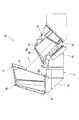
図1は、実施形態に係るヘッドアップディスプレイ装置の斜視図、図2は、実施形態に係るヘッドアップディスプレイ装置のコンバイナの正面図、図3は、実施形態に係るヘッドアップディスプレイ装置の断面図、図4は、実施形態に係るヘッドアップディスプレイ装置の分解斜視図である。 1 is a perspective view of a head-up display device according to the embodiment, FIG. 2 is a front view of a combiner of the head-up display device according to the embodiment, and FIG. 3 is a cross-sectional view of the head-up display device according to the embodiment. FIG. 4 is an exploded perspective view of the head-up display device according to the embodiment.
図1に示すように、本実施形態に係る車両用表示装置であるヘッドアップディスプレイ装置10は、表示装置本体11と、この表示装置本体11の上部に固定されたコンバイナ12とを備えている。 As shown in FIG. 1, a head-up
表示装置本体11は、車両のダッシュボード内に収容されるもので、この表示装置本体11からコンバイナ12へ表示光が照射される。 The
コンバイナ12は、車両のダッシュボード上に配置され、表示装置本体11から表示光が照射される。これにより、このコンバイナ12には、虚像が投影され、この虚像は、車両の運転者のアイポイントから視認される。 The
コンバイナ12は、合成樹脂から成形されたもので、図2に示すように、透光性を有する透光部21を有している。この透光部21は、その中央部分が表示領域Aとされており、この表示領域Aに、表示装置本体11からの表示光が照射されて虚像が形成される。この虚像は、例えば、車両の走行速度、燃料やバッテリの残量、あるいは駆動機構部の温度等の情報表示H1である。 The
また、このコンバイナ12の透光部21は、表示領域Aの外側である両側が透明透過部Bとされている。この透明透過部Bは、目視した際に、透明と認識可能な領域とされている。 Moreover, the
コンバイナ12における表示領域A及び透明透過部Bを有する透光部21の下方側は、有色領域Cとされている。この有色領域Cは、例えば、印刷または塗装によって幅方向へわたって黒色に着色されている。また、コンバイナ12の透光部21の上部には、上縁に沿って表示光の照射側に突出するフード部23が一体成形されており、このフード部23は、例えば、黒色等に着色されている。このフード部23は、コンバイナ12を成形する際に、黒色の樹脂を用いて二色成形することで形成されている。 The lower side of the
そして、コンバイナ12は、黒色の有色領域C及び黒色のフード部23を設けたことで、表示領域Aに投影される情報表示H1に対する外光の影響が抑えられ、また、外光が反射して車内へ照射されることが抑制される。 The
なお、有色領域C及びフード部23の色は、黒色に限らず、例えば、濃灰色等の暗色系の色でもよい。 Note that the color of the colored region C and the
表示装置本体11は、二つの画像表示部25を備えている。これらの画像表示部25は、表示装置本体11の両側部で上方に突出するように設けられている。これにより、これらの画像表示部25は、表示装置本体11に固定したコンバイナ12の透光部21における透明透過部Bの裏面側に配置されている。 The
画像表示部25は、コンバイナ12側に実像からなる画像を表示するもので、図2に示すように、これらの画像表示部25で表示された画像は、コンバイナ12の透光部21における表示領域Aの両側の透明透過部Bを通して視認可能とされている。これらの画像表示部25で表示する画像は、例えば、車両の走行の補助や状態等のサポート表示H2である。 The
また、表示装置本体11の両側部には、像投影部26が設けられている。これらの像投影部26は、コンバイナ12の透光部21における表示領域Aの両側の透明透過部Bへ表示光を照射する。これにより、コンバイナ12の透明透過部Bには、虚像が投影される。 In addition,
これにより、コンバイナ12の透明透過部Bには、画像表示部25の画像からなるサポート表示H2とともに、像投影部26によって投影された虚像からなる表示を組み合わせることが可能とされている。 Thereby, it is possible to combine the display made of a virtual image projected by the
次に、ヘッドアップディスプレイ装置10の具体的な構造について説明する。 Next, a specific structure of the head-up
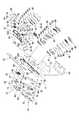
図3及び図4に示すように、ヘッドアップディスプレイ装置10を構成する表示装置本体11は、合成樹脂等から成形されたケース30を有している。このケース30には、その上面に、幅方向へわたって取付溝部30aが形成されており、コンバイナ12は、このケース30の取付溝部30aに挿し込まれて固定されている。 As shown in FIGS. 3 and 4, the
ケース30には、幅方向の中央における手前側に、画像形成装置31が組み付けられている。 An
画像形成装置31は、ハウジング32を有しており、このハウジング32には、画像形成アッシー33及び複数のアンビエントアッシー34が組み付けられている。 The
画像形成アッシー33は、シールド板40、LCDパネル41、ターンレンズ42、光源ケース43、ターンプリズム44、レンズアレイ45、虚像アルミ基板46、伝熱シート47及びヒートシンク48を有しており、これらがハウジング32へ順に組み付けられて構成されている。 The
この画像形成アッシー33では、虚像アルミ基板46に設けられたLED等の光源49で発光した光がレンズアレイ45で集光され、ターンプリズム44及びターンレンズ42を通してLCDパネル41へ照射される。これにより、このLCDパネル41の画像が表示光Lとしてシールド板40を介してハウジング32内へ照射される。 In the
また、アンビエントアッシー34は、アンビエントケース51、アンビエントプリズム52、アンビエントアルミ基板53、伝熱シート54及びヒートシンク55を有しており、これらがハウジング32へ順に組み付けられて構成されている。 In addition, the
このアンビエントアッシー34では、アンビエントアルミ基板53に設けられたLED等の光源56で発光した光がアンビエントプリズム52及びアンビエントケース51を通してハウジング32内へ照射される。 In the
ハウジング32には、その上部に開口部32aが形成されており、この開口部32aには、表ガラス35が取り付けられている。そして、ハウジング32に導かれた画像形成アッシー33からの表示光L及びアンビエント照明光は、ハウジング32の開口部32aの表ガラス35を介してハウジング32の外部へ出射され、コンバイナ12の表示領域Aへ照射され、運転者のアイレンジに導かれる。 The
これにより、運転者は、車両のアイポイントからコンバイナ12の表示領域Aに投影された虚像からなる情報表示H1を視認することができる。また、この表示領域Aは、アンビエントアッシー34からの照明光で装飾される。 Thereby, the driver | operator can visually recognize the information display H1 which consists of a virtual image projected on the display area A of the
また、ケース30には、その両側部における上部に、取付枠60が一体成形されており、これらの取付枠60に、画像表示部25を構成する画像表示部アッシー61が組み付けられている。 Further, the
画像表示部アッシー61は、画像アッシー部62と、表示アッシー部63とを有している。画像アッシー部62は、画像を表示させるもので、光学フィルム65、TFTパネル66及びパネル固定板67を有しており、これらが順に取付枠60に組み付けられている。表示アッシー部63は、警告等を表示するもので、警告レンズ板68、光源ケース69及び光源基板70を有しており、これらが順に取付枠60に組み付けられている。そして、これらの画像アッシー部62及び表示アッシー部63の背面側からカバー75が取り付けられ、画像表示部アッシー61とされている。なお、一方側の画像表示部アッシー61の表示アッシー部63には、LCDパネル71も組み込まれている。 The image
この画像表示部アッシー61では、画像アッシー部62のTFTパネル66に映し出される画像が、光学フィルム65を介してコンバイナ12側へ表示され、また、表示アッシー部63の光源基板70に設けられたLED等の光源72の光が警告レンズ板68に照射され、警告表示の表示光としてコンバイナ12側へ照射される。 In this image
これにより、運転者は、車両のアイポイントからコンバイナ12の透明透過部Bを介して画像表示部25の画像や表示からなるサポート表示H2を視認することができる。 As a result, the driver can visually recognize the support display H <b> 2 including the image and display on the
また、ケース30には、画像形成装置31の装着箇所の両側に、像投影部26が組み付けられている。 In addition, the
像投影部26は、ガラス板81、カバー82、文字板83、拡散板84、光源カバー85、光源基板86、伝熱シート87、ヒートシンク88及びヒートシンクカバー89を有しており、これらがケース30へ順に組み付けられている。 The
そして、この像投影部26では、光源基板86に設けられたLED等の光源90からの光が、拡散板84で拡散され、その後、文字板83及びガラス板81を透過して出射する。像投影部26は、コンバイナ12に対して斜めに設置されており、これにより、像投影部26から出射した表示光Lは、コンバイナ12の透明透過部Bへ斜め下方側から照射される。これにより、コンバイナ12の透明透過部Bには、画像表示部25の画像からなる表示とともに、像投影部26によって投影された虚像からなる表示を組み合わせることができる。 In the
また、ケース30には、その底部側に、制御基板91が装着されており、この制御基板91は、ケース30の底部に固定されるカバー93で覆われている。この制御基板91は、画像形成装置31、画像表示部25、像投影部26を制御する制御回路を備えている。 Further, the
上記構成のヘッドアップディスプレイ装置10では、画像形成装置31から照射された表示光Lが、コンバイナ12の表示領域Aへ照射され、運転者のアイレンジに導かれる。これにより、運転者は、車両のアイポイントからコンバイナ12の表示領域Aに投影された虚像からなる情報表示H1の視認が可能となる。 In the head-up
また、コンバイナ12の表示領域Aの両側部の透明透過部Bでは、コンバイナ12を介して画像表示部25の画像が表示される。これにより、運転者は、車両のアイポイントからコンバイナ12の表示領域Aの両側部の透明透過部Bのサポート表示H2も視認可能となる。 In addition, in the transparent transmission part B on both sides of the display area A of the
さらに、この透明透過部Bでは、画像表示部25の画像からなるサポート表示H2とともに、像投影部26によって投影された虚像からなる表示も組み合わされる。これにより、運転者は、車両のアイポイントからコンバイナ12の表示領域Aの両側部の透明透過部Bのサポート表示H2にさらに虚像が組み合わされた表示も視認可能となる。 Furthermore, in this transparent transmission part B, the display which consists of the virtual image projected by the
以上、説明したように、上記の車両用表示装置であるヘッドアップディスプレイ装置によれば、表示装置本体11からの表示光Lが投影されるコンバイナ12は、表示光Lが投影される表示領域Aの少なくとも片側に透明透過部Bを有する。これにより、透明透過部Bの存在により、良好な視認性を確保しつつコンバイナ12に広がりを持たせることができ、表示領域Aの情報表示H1との一体感を生じさせてデザイン性を向上させることができる。 As described above, according to the head-up display device that is the above-described vehicle display device, the
しかも、画像表示部25によって、表示領域Aへの表示とは別のサポート表示H2を透明透過部Bに表示させることができるので、デザイン性をさらに向上させることができるとともに、表示機能を高めることができる。 In addition, since the support display H2 different from the display in the display area A can be displayed on the transparent transmission part B by the
また、画像表示部25によってサポート表示H2が表示される透明透過部Bに、像投影部26によって虚像を投影することができる。これにより、透明透過部Bにおける表示機能をさらに高めることができる。 Further, a virtual image can be projected by the
なお、上記実施形態では、コンバイナ12における表示領域Aの両側に透明透過部Bを設けたが、この透明透過部Bは、コンバイナ12における表示領域Aの少なくとも片側に設けてもよい。この場合、透明透過部Bにサポート表示H2を表示させる画像表示部25及び透明透過部Bに虚像を投影する像投影部26は、透明透過部Bが設けられた片側に設けることとなる。 In the above-described embodiment, the transparent transmission part B is provided on both sides of the display area A in the
また、上記実施形態では、画像形成装置31からの表示光Lをコンバイナ12へ直接投影させる構成としたが、画像形成装置31からの表示光Lを非球面ミラーや平面ミラー等のミラーで1回反射させてコンバイナ12へ投影してもよく、または、画像形成装置31からの表示光Lを2回以上反射させてコンバイナ12へ投影させる構造としてもよい。 In the above embodiment, the display light L from the
また、上記実施形態では、表示装置本体11に画像表示部25を一体的に設けてコンバイナ12の背面に配置させたが、画像表示部25を表示装置本体11とは別体とし、この別体の画像表示部25をコンバイナ12の背面に取り付ける構造としてもよい。 In the above-described embodiment, the
尚、本発明は、上述した実施形態に限定されるものではなく、適宜、変形、改良、等が可能である。その他、上述した実施形態における各構成要素の材質、形状、寸法、数、配置箇所、等は本発明を達成できるものであれば任意であり、限定されない。 In addition, this invention is not limited to embodiment mentioned above, A deformation | transformation, improvement, etc. are possible suitably. In addition, the material, shape, dimensions, number, arrangement location, and the like of each component in the above-described embodiment are arbitrary and are not limited as long as the present invention can be achieved.
10 ヘッドアップディスプレイ装置(車両用表示装置)
11 表示装置本体
12 コンバイナ
25 画像表示部
26 像投影部
A 表示領域
B 透明透過部10 Head-up display device (vehicle display device)
DESCRIPTION OF
Claims (2)
Translated fromJapanese該表示装置本体の上部に固定されて前記表示装置本体から出射される表示光が投影されるコンバイナと、
を備えた車両用表示装置であって、
前記コンバイナは、前記表示光が投影される表示領域と、この表示領域の少なくとも片側に設けられた透明透過部とを有し、
前記コンバイナの前記透明透過部の背面側には、画像を表示させる画像表示部が設けられている
ことを特徴とする車両用表示装置。A display device body for emitting display light;
A combiner that is fixed to the upper portion of the display device body and that projects display light emitted from the display device body; and
A vehicle display device comprising:
The combiner includes a display area on which the display light is projected, and a transparent transmission portion provided on at least one side of the display area,
An image display unit that displays an image is provided on the back side of the transparent transmission unit of the combiner.
ことを特徴とする請求項1に記載の車両用表示装置。The vehicle display device according to claim 1, wherein the display device body includes an image projection unit that projects display light different from the display light projected onto the display region onto the transparent transmission unit.
Priority Applications (1)
| Application Number | Priority Date | Filing Date | Title |
|---|---|---|---|
| JP2011267262AJP5961372B2 (en) | 2011-12-06 | 2011-12-06 | Vehicle display device |
Applications Claiming Priority (1)
| Application Number | Priority Date | Filing Date | Title |
|---|---|---|---|
| JP2011267262AJP5961372B2 (en) | 2011-12-06 | 2011-12-06 | Vehicle display device |
Publications (2)
| Publication Number | Publication Date |
|---|---|
| JP2013119286Atrue JP2013119286A (en) | 2013-06-17 |
| JP5961372B2 JP5961372B2 (en) | 2016-08-02 |
Family
ID=48772159
Family Applications (1)
| Application Number | Title | Priority Date | Filing Date |
|---|---|---|---|
| JP2011267262AActiveJP5961372B2 (en) | 2011-12-06 | 2011-12-06 | Vehicle display device |
Country Status (1)
| Country | Link |
|---|---|
| JP (1) | JP5961372B2 (en) |
Cited By (3)
| Publication number | Priority date | Publication date | Assignee | Title |
|---|---|---|---|---|
| WO2017006506A1 (en)* | 2015-07-03 | 2017-01-12 | 株式会社デンソー | On-vehicle display device |
| JP2017013774A (en)* | 2015-07-03 | 2017-01-19 | 株式会社デンソー | Vehicular display device |
| JP2017072577A (en)* | 2015-10-05 | 2017-04-13 | 株式会社デンソー | Vehicle display device |
Citations (5)
| Publication number | Priority date | Publication date | Assignee | Title |
|---|---|---|---|---|
| JP2000267039A (en)* | 1999-03-15 | 2000-09-29 | Shimadzu Corp | Head-up display |
| JP2002356118A (en)* | 2001-05-31 | 2002-12-10 | Yazaki Corp | Display device for vehicles |
| JP2003063275A (en)* | 2001-08-24 | 2003-03-05 | Minolta Co Ltd | Head-up display device |
| JP2003237412A (en)* | 2002-02-14 | 2003-08-27 | Denso Corp | Vehicle head-up display device |
| JP2010072365A (en)* | 2008-09-18 | 2010-04-02 | Toshiba Corp | Head up display |
- 2011
- 2011-12-06JPJP2011267262Apatent/JP5961372B2/enactiveActive
Patent Citations (5)
| Publication number | Priority date | Publication date | Assignee | Title |
|---|---|---|---|---|
| JP2000267039A (en)* | 1999-03-15 | 2000-09-29 | Shimadzu Corp | Head-up display |
| JP2002356118A (en)* | 2001-05-31 | 2002-12-10 | Yazaki Corp | Display device for vehicles |
| JP2003063275A (en)* | 2001-08-24 | 2003-03-05 | Minolta Co Ltd | Head-up display device |
| JP2003237412A (en)* | 2002-02-14 | 2003-08-27 | Denso Corp | Vehicle head-up display device |
| JP2010072365A (en)* | 2008-09-18 | 2010-04-02 | Toshiba Corp | Head up display |
Cited By (3)
| Publication number | Priority date | Publication date | Assignee | Title |
|---|---|---|---|---|
| WO2017006506A1 (en)* | 2015-07-03 | 2017-01-12 | 株式会社デンソー | On-vehicle display device |
| JP2017013774A (en)* | 2015-07-03 | 2017-01-19 | 株式会社デンソー | Vehicular display device |
| JP2017072577A (en)* | 2015-10-05 | 2017-04-13 | 株式会社デンソー | Vehicle display device |
Also Published As
| Publication number | Publication date |
|---|---|
| JP5961372B2 (en) | 2016-08-02 |
Similar Documents
| Publication | Publication Date | Title |
|---|---|---|
| JP5941292B2 (en) | Vehicle display device | |
| US10551618B2 (en) | Vehicle display device | |
| US20110175798A1 (en) | Display device for vehicle | |
| KR101823180B1 (en) | Vehicular heads-up display device | |
| WO2010103596A1 (en) | Head-up display device | |
| JP2015090483A (en) | Information display device | |
| WO2018051683A1 (en) | Mid-air display device | |
| JP5888003B2 (en) | Head-up display device | |
| JP5961372B2 (en) | Vehicle display device | |
| JP6046340B2 (en) | Vehicle display device | |
| JP2012108470A (en) | Head-up display device | |
| JP6046368B2 (en) | Vehicle display device | |
| JP6210425B2 (en) | Head-up display device | |
| JP7484726B2 (en) | Head-up display device | |
| JP6382009B2 (en) | Bezel body and display device for vehicle having the same | |
| JP2019006180A (en) | Display device | |
| JP2010282108A (en) | Head-up display device for vehicle | |
| JP6304755B2 (en) | Bezel body and display device for vehicle having the same | |
| JP2019008030A (en) | Display device | |
| JP6398466B2 (en) | Display device | |
| JP4652787B2 (en) | Display device | |
| JP6041129B2 (en) | Display device | |
| JP2016060333A (en) | Display device | |
| JP2016057589A (en) | Head-up display device | |
| JP2006113024A (en) | Pointing instrument |
Legal Events
| Date | Code | Title | Description |
|---|---|---|---|
| A621 | Written request for application examination | Free format text:JAPANESE INTERMEDIATE CODE: A621 Effective date:20141119 | |
| RD02 | Notification of acceptance of power of attorney | Free format text:JAPANESE INTERMEDIATE CODE: A7422 Effective date:20150122 | |
| A131 | Notification of reasons for refusal | Free format text:JAPANESE INTERMEDIATE CODE: A131 Effective date:20151117 | |
| A521 | Request for written amendment filed | Free format text:JAPANESE INTERMEDIATE CODE: A523 Effective date:20151222 | |
| TRDD | Decision of grant or rejection written | ||
| A01 | Written decision to grant a patent or to grant a registration (utility model) | Free format text:JAPANESE INTERMEDIATE CODE: A01 Effective date:20160531 | |
| A61 | First payment of annual fees (during grant procedure) | Free format text:JAPANESE INTERMEDIATE CODE: A61 Effective date:20160627 | |
| R150 | Certificate of patent or registration of utility model | Ref document number:5961372 Country of ref document:JP Free format text:JAPANESE INTERMEDIATE CODE: R150 | |
| R250 | Receipt of annual fees | Free format text:JAPANESE INTERMEDIATE CODE: R250 | |
| R250 | Receipt of annual fees | Free format text:JAPANESE INTERMEDIATE CODE: R250 | |
| R250 | Receipt of annual fees | Free format text:JAPANESE INTERMEDIATE CODE: R250 | |
| R250 | Receipt of annual fees | Free format text:JAPANESE INTERMEDIATE CODE: R250 | |
| S531 | Written request for registration of change of domicile | Free format text:JAPANESE INTERMEDIATE CODE: R313531 | |
| R350 | Written notification of registration of transfer | Free format text:JAPANESE INTERMEDIATE CODE: R350 | |
| R250 | Receipt of annual fees | Free format text:JAPANESE INTERMEDIATE CODE: R250 | |
| R250 | Receipt of annual fees | Free format text:JAPANESE INTERMEDIATE CODE: R250 |