JP2013119151A - Finger joint structure - Google Patents
Finger joint structureDownload PDFInfo
- Publication number
- JP2013119151A JP2013119151AJP2011269474AJP2011269474AJP2013119151AJP 2013119151 AJP2013119151 AJP 2013119151AJP 2011269474 AJP2011269474 AJP 2011269474AJP 2011269474 AJP2011269474 AJP 2011269474AJP 2013119151 AJP2013119151 AJP 2013119151A
- Authority
- JP
- Japan
- Prior art keywords
- finger
- shape
- wire
- joint structure
- hollow body
- Prior art date
- Legal status (The legal status is an assumption and is not a legal conclusion. Google has not performed a legal analysis and makes no representation as to the accuracy of the status listed.)
- Pending
Links
- 210000001145finger jointAnatomy0.000titleclaimsabstractdescription40
- 230000000149penetrating effectEffects0.000claimsabstractdescription12
- 239000000463materialSubstances0.000claimsdescription13
- 239000011347resinSubstances0.000claimsdescription13
- 229920005989resinPolymers0.000claimsdescription13
- 229910001220stainless steelInorganic materials0.000claimsdescription12
- 239000010935stainless steelSubstances0.000claimsdescription12
- 230000001788irregularEffects0.000claimsdescription11
- RTAQQCXQSZGOHL-UHFFFAOYSA-NTitaniumChemical compound[Ti]RTAQQCXQSZGOHL-UHFFFAOYSA-N0.000claimsdescription10
- 229910052719titaniumInorganic materials0.000claimsdescription10
- 239000010936titaniumSubstances0.000claimsdescription10
- 229910045601alloyInorganic materials0.000claimsdescription9
- 239000000956alloySubstances0.000claimsdescription9
- 229910001069Ti alloyInorganic materials0.000claimsdescription8
- 229910001285shape-memory alloyInorganic materials0.000claimsdescription8
- 239000002131composite materialSubstances0.000claimsdescription6
- 238000005452bendingMethods0.000description14
- 238000000034methodMethods0.000description8
- 229910001000nickel titaniumInorganic materials0.000description6
- 238000010586diagramMethods0.000description5
- 229920001343polytetrafluoroethylenePolymers0.000description5
- 239000004810polytetrafluoroethyleneSubstances0.000description5
- 229910052751metalInorganic materials0.000description4
- 239000002184metalSubstances0.000description4
- -1polytetrafluoroethylenePolymers0.000description4
- 239000004952PolyamideSubstances0.000description3
- 229920002647polyamidePolymers0.000description3
- 229910001040Beta-titaniumInorganic materials0.000description2
- 230000005540biological transmissionEffects0.000description2
- HLXZNVUGXRDIFK-UHFFFAOYSA-Nnickel titaniumChemical compound[Ti].[Ti].[Ti].[Ti].[Ti].[Ti].[Ti].[Ti].[Ti].[Ti].[Ti].[Ni].[Ni].[Ni].[Ni].[Ni].[Ni].[Ni].[Ni].[Ni].[Ni].[Ni].[Ni].[Ni].[Ni]HLXZNVUGXRDIFK-UHFFFAOYSA-N0.000description2
- 229920006358FluonPolymers0.000description1
- YCKRFDGAMUMZLT-UHFFFAOYSA-NFluorine atomChemical compound[F]YCKRFDGAMUMZLT-UHFFFAOYSA-N0.000description1
- 239000004809TeflonSubstances0.000description1
- 229920006362Teflon®Polymers0.000description1
- HZEWFHLRYVTOIW-UHFFFAOYSA-N[Ti].[Ni]Chemical compound[Ti].[Ni]HZEWFHLRYVTOIW-UHFFFAOYSA-N0.000description1
- 230000003247decreasing effectEffects0.000description1
- 229910052731fluorineInorganic materials0.000description1
- 239000011737fluorineSubstances0.000description1
- 230000006870functionEffects0.000description1
- 229920000139polyethylene terephthalatePolymers0.000description1
- 239000005020polyethylene terephthalateSubstances0.000description1
- 229920000098polyolefinPolymers0.000description1
- 229920001296polysiloxanePolymers0.000description1
- 229920002635polyurethanePolymers0.000description1
- 239000004814polyurethaneSubstances0.000description1
- 238000011084recoveryMethods0.000description1
- 238000004804windingMethods0.000description1
Images


Landscapes
- Manipulator (AREA)
Abstract
Description
Translated fromJapanese本発明は、指関節構造に関する。 The present invention relates to a finger joint structure.
ロボットなどの指関節構造は、複数の指部材と各部材同士を回動可能に接続するヒンジ部(関節)とを備えている。 A finger joint structure such as a robot includes a plurality of finger members and hinge portions (joints) that connect the members to each other so as to be rotatable.
これら複数の関節を回動させる方法として、例えば、各関節にワイヤを巻きつけ、ワイヤを介して駆動手段の動力を各関節に伝達し、関節を回動させる方法(特許文献1)、各関節に直接駆動手段を設け、直接関節を回動させる方法(特許文献2)、1つの駆動手段により3つの関節を駆動させることが可能な指関節構造(特許文献3)が提案されている。 As a method for rotating the plurality of joints, for example, a method of rotating a joint by winding a wire around each joint and transmitting the power of the driving means to each joint via the wire (Patent Document 1), There is proposed a method of directly driving a joint and rotating a joint directly (Patent Document 2), and a finger joint structure (Patent Document 3) capable of driving three joints by one driving means.
特許文献1の方法では、関節ごとに駆動手段とワイヤが必要になり、ワイヤは牽引することで関節を回動するため、関節の屈曲動作、伸長動作を行うワイヤがそれぞれ必要になるという問題がある。また、特許文献2の方法では、関節ごとに駆動手段を設ける必要があり、関節構造が大型化するという問題がある。さらに、特許文献3の方法では、1つの駆動手段により3つの関節を駆動させるために、複雑な構造が必要になるという問題がある。 In the method of
このように、従来の指関節構造においては、複雑な構造、大型の構造が必要であり、構造の簡易化、小型化が困難であった。 As described above, the conventional finger joint structure requires a complicated structure and a large structure, and it is difficult to simplify and miniaturize the structure.
本発明は、簡易かつ小型の指関節構造を提供することを目的とする。 An object of the present invention is to provide a simple and small finger joint structure.
本発明者らは、上記課題を解決するために、鋭意検討を重ねた結果、遠位端側から近位端側に、指部、掌部、および基部の順で構成される指関節構造において、指部を複数の筒体が端面で連接してなる中空体と、中空体を貫通する少なくとも1本のワイヤとから構成し、中空体の遠位端とワイヤの遠位端とが接合され、中空体の近位端が掌部の遠位端に固定され、ワイヤの少なくとも1本がさらに掌部を貫通して基部に到達することによって、基部において、ワイヤの近位端を基部側に牽引することによって、指部が剛性のある屈曲形状を発現し得ることを見出し、本発明を完成させた。 In order to solve the above-mentioned problems, the present inventors have conducted extensive studies, and as a result, in a finger joint structure configured in the order of a finger part, a palm part, and a base part from the distal end side to the proximal end side. The finger part is composed of a hollow body formed by connecting a plurality of cylindrical bodies at end faces, and at least one wire penetrating the hollow body, and the distal end of the hollow body and the distal end of the wire are joined. The proximal end of the hollow body is fixed to the distal end of the palm, and at least one of the wires further penetrates the palm and reaches the base, so that the proximal end of the wire is proximal to the base. The present inventors have found that by pulling, the finger portion can express a rigid bent shape.
本発明は、遠位端を有する指部、該指部に延設された掌部、および該掌部の近位端に設けられた基部を備える指関節構造を提供し、該関節構造において、該指部は、異形断面を有する複数の筒体が端面で連接してなる中空体と該中空体を貫通する少なくとも1本のワイヤとから構成され、該筒体の少なくとも1つは、軸方向に対して垂直でない端面を有し、該ワイヤの少なくとも1本は、該中空体の内径の短径の80%以上である長径の異形断面を有し、該中空体の遠位端と該ワイヤの遠位端とが接合され、該中空体の近位端は該掌部の遠位端に固定され、該ワイヤの少なくとも1本はさらに該掌部を貫通して該基部に到達し、そして該基部において、該ワイヤの近位端を基部側に牽引することによって、該指部が屈曲形状を発現し得る。 The present invention provides a finger joint structure comprising a finger portion having a distal end, a palm portion extending to the finger portion, and a base portion provided at a proximal end of the palm portion, The finger portion includes a hollow body formed by connecting a plurality of cylindrical bodies having irregular cross-sections at end faces, and at least one wire penetrating the hollow body, and at least one of the cylindrical bodies has an axial direction. And at least one of the wires has a deformed cross section having a major axis that is 80% or more of the minor axis of the inner diameter of the hollow body, the distal end of the hollow body and the wire The proximal end of the hollow body is secured to the distal end of the palm, at least one of the wires further penetrates the palm to reach the base, and By pulling the proximal end of the wire to the base side at the base portion, the finger portion can develop a bent shape.
1つの実施態様では、2本以上のワイヤが上記中空体を貫通する。 In one embodiment, two or more wires penetrate the hollow body.
1つの実施態様では、上記筒体の異形断面の形状は、楕円状、レーストラック形状、長方形状、正方形状、三角形状または五角形状である。 In one embodiment, the shape of the irregular cross section of the cylinder is an ellipse, a race track, a rectangle, a square, a triangle, or a pentagon.
1つの実施態様では、上記ワイヤの異形断面の形状は、楕円状、レーストラック形状、長方形状または台形状である。 In one embodiment, the shape of the irregular cross section of the wire is an ellipse, a racetrack, a rectangle or a trapezoid.
1つの実施態様では、上記筒体の材質は、ステンレス、チタン、チタン合金、形状記憶合金、超弾性合金またはこれらの複合体から選択される。 In one embodiment, the material of the cylinder is selected from stainless steel, titanium, a titanium alloy, a shape memory alloy, a superelastic alloy, or a composite thereof.
1つの実施態様では、上記ワイヤの材質は、ステンレス、チタン、チタン合金、形状記憶合金、超弾性合金またはこれらの複合体から選択される。 In one embodiment, the material of the wire is selected from stainless steel, titanium, titanium alloy, shape memory alloy, superelastic alloy, or a composite thereof.
1つの実施態様では、上記指部は、樹脂製カバーで被覆されている。 In one embodiment, the finger portion is covered with a resin cover.
本発明によれば、簡易かつ小型の指関節構造を提供することができる。本発明の指関節構造は、基部の操作により屈曲形状を速やかに発現する。指部を構成する中空体の隣接する筒体の端面の角度を適宜設定することによって、任意の屈曲形状を発現できる。複数の指関節構造を組み合わせることによって、発現した屈曲形状により自在に物を把持することができる。駆動力の伝達にワイヤの弾性を積極的に介在させることによって、把持対象物に対する衝撃を緩和することができる。 According to the present invention, a simple and small finger joint structure can be provided. The finger joint structure of the present invention quickly develops a bent shape by operating the base. An arbitrary bent shape can be expressed by appropriately setting the angle of the end face of the adjacent cylindrical body of the hollow body constituting the finger part. By combining a plurality of finger joint structures, an object can be gripped freely by the expressed bent shape. By positively interposing the elasticity of the wire in the transmission of the driving force, the impact on the grasped object can be reduced.
本明細書において、用語「遠位端」とは、操作者から最も遠い部分をいい、そして用語「近位端」とは、操作者に最も近い部分をいう。 As used herein, the term “distal end” refers to the portion furthest from the operator, and the term “proximal end” refers to the portion closest to the operator.
本明細書において、用語「屈曲形状」とは、曲線が形成する任意の形状をいい、3次元の形状を含む。 In this specification, the term “bent shape” refers to an arbitrary shape formed by a curve, and includes a three-dimensional shape.
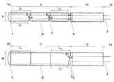
図1および2を参照すると、本発明の指関節構造1は、指部11、指部11に延設された掌部12、および掌部12の近位端に設けられた基部13を備える。各部の寸法は、特に限定されない。 Referring to FIGS. 1 and 2, the
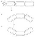
指部11は、屈曲形状を発現しない際は、直線形状をとる(図1(a)ならびに図2(a−1)および(a−1’))。屈曲形状としては、特に限定されず、例えば、円弧状が挙げられる(図1(b)ならびに図2(a−2)および(a−2’))。 When the
指部11は、複数の筒体21が端面で連接してなる中空体2と中空体2を貫通する少なくとも1本のワイヤ3とから構成される。本発明の指関節構造1は、ワイヤ3の断面の長径を小さくすることによって、小型化が可能である。例えば、指部11の最大外径を3mm以下にすることができる。 The
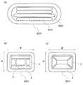
筒体21は異形断面を有する。ここで、異形とは、標準形とは異なる特殊な形状をいう。筒体21の断面形状の標準形は円であり、異形としては、例えば、楕円状、レーストラック形状、長方形状、正方形状、三角形状、五角形状が挙げられる。 The
筒体21の数としては、上記指部11を形成することができる限り、特に限定されない。好ましくは、3個以上である。筒体21の数が多いほど、発現する屈曲形状を滑らかにすることができる。 The number of
図2を参照すると、指部11は、多数の筒体21を有し、屈曲形状を発現することによって、対象物を把持することができ、または包み込むことができる。 Referring to FIG. 2, the
筒体21の少なくとも1つは、軸方向に対して垂直でない端面を有する。例えば、図3(a)のように、筒体21の断面形状が扁平形状の場合、図1(a)に示すように、扁平面を上下にした筒体21の側面形状において、端面は軸方向に対して垂直な面から一定の角度θ1〜θ3をつけて逆V字型またはV字型のノッチを形成する。θ1の場合は、側面形状の上辺L1は下辺L2より長いため、逆V字型のノッチである。θ2の場合も同様である。一方、θ3の場合は、側面形状の上辺は下辺より短いため、V字型のノッチである。角度θ1〜θ3の大きさは、それぞれ同じであってもよいし、異なっていてもよい。角度θのノッチは、筒体21の2つの端面のいずれか一方に形成してもよいし、両方に形成してもよい。両方に形成する場合、両方の角度θは同じであってもよいし、異なっていてもよい。At least one of the
あるいは、図4(a)に示すように、垂直な面から一定の角度θ1およびθ2をつけて逆V字型ノッチおよびV字型ノッチを側面形状のそれぞれ上辺側および下辺側の両方に形成してもよい。角度θ1およびθ2の大きさは、それぞれ同じであってもよいし、異なっていてもよい。上辺側の逆V字型ノッチの高さH1と下辺側のV字型ノッチの高さH2とは、同じであってもよいし、異なっていてもよいが、筒体21の高さHとH1およびH2とは、H=H1+H2の関係を満たす。連接する筒体21の上辺側と下辺側との両方にノッチを設けることにより、指部11が屈曲する方向を、図4(b)のように下辺側にすることもできるし、図4(c)のように上辺側にすることもできる。Alternatively, as shown in FIG. 4 (a), the inverted V-shaped notch and the V-shaped notch are provided on both the upper side and the lower side of the side surface shape with a certain angle θ1 and θ2 from the vertical plane. It may be formed. The magnitudes of the angles θ1 and θ2 may be the same or different. The height H2 of the V-shaped notch of height H1 and the lower side of the inverted V-shaped notch upper side may be the same, may be different, the height of the cylindrical body 21 H and H1 and H2 satisfy the relationship of H = H1 + H2 . By providing notches on both the upper side and the lower side of the
さらに、屈曲形状は、同一平面上の形状に限定されない。例えば、図3(b)のように、筒体21の断面形状が長方形状の場合、図5に示すように、長辺面を上下にした筒体21の側面形状(a)において、端面は軸方向に対して垂直な面から一定の角度θ1およびθ2をつけて逆V字型のノッチを形成し、平面形状(b)において、端面は軸方向に対して垂直な面から一定の角度θ3をつけて逆V字型のノッチを形成する。このように、筒体21によりθを形成する面を変えることによって、3次元の屈曲形状が可能となる。このことは、筒体21の断面形状が長方形状でない場合も同様である。Further, the bent shape is not limited to a shape on the same plane. For example, as shown in FIG. 3B, when the cross-sectional shape of the
複数の筒体21が端面で連接してなる中空体2は、中空体2を貫通するワイヤ3の形状に従って直線形状をとり得、隣接する筒体21同士の端面間は角度θを有する逆V字型のノッチが形成されている。中空体2は、ワイヤ3の基部側への牽引により両端から押圧されると、隣接する筒体21同士の端面間の角度が0°となるまで、すなわち端面間が密着して接するまで、中空体2を貫通するワイヤ3とともに図1(b)、図2(a−2)および(a−2’)、ならびに図4(b)および(c)のような屈曲した形状を発現する。 The
角度θは、発現する屈曲形状に応じて適宜設定される。また、角度θの端面を有する筒体21をどのように配置するかも、発現する屈曲形状に応じて適宜設定される。 The angle θ is appropriately set according to the bending shape that is manifested. Further, how to arrange the
筒体21の寸法は、特に限定されない。筒体21の外径における長径に対する短径の比(%)(例えば、扁平率)は、特に限定されない。この比が大きいほど、中空体2の屈曲指向性を大きくすることができるが、大きすぎると中空体2の剛性が低くなる。筒体21の筒厚は、指部11の剛性を確保できる限り、特に限定されない。 The dimension of the
筒体21の材質は、特に限定されないが、好ましくは金属である。金属としては、例えば、ステンレス、チタン、チタン合金、形状記憶合金、超弾性合金、これらの複合体が挙げられる。ステンレスとしては、例えば、SUS304、SUS316、SUS316Lが挙げられる。チタン、チタン合金としては、例えば、純チタン、βチタンが挙げられる。形状記憶合金、超弾性合金としては、例えば、ニチノール(ニッケル−チタン合金)が挙げられる。筒体21の材質としては、剛性である限り、樹脂であってもよい。樹脂としては、例えば、ポリアミド、ポリテトラフルオロエチレン(PTFE)が挙げられる。 Although the material of the
ワイヤ3の数は、中空体2およびワイヤ3の剛性に応じて適宜設定される。通常1〜6本であり、好ましくは2〜4本である。 The number of
ワイヤ3の少なくとも1本は、中空体2の内径の長径より小さく、かつ短径の80%以上であり、好ましくは短径より大きい長径の異形断面を有する。ワイヤの断面の標準形は円であり、異形としては、例えば、楕円状、レーストラック形状、長方形状、台形状が挙げられる。図3(a)はレーストラック形状の一例を示す。図3(b)は長方形状の一例を示す。図3(c)は台形状の一例を示す。 At least one of the
ワイヤ3の長径を筒体21の内径の短径の80%以上、好ましくは短径より大きくすることによって、中空体2の扁平面または長辺面とワイヤ3の異形断面の長径面とを一致させることができ、ワイヤ3が中空体2の中で、軸回りに自由回転することを防止することができる。筒体21の内径の短径に対する、筒体21を貫通するすべてのワイヤ3の異形断面の短径の和の比(%)は、特に限定されないが、中空体2の形状維持(ずれ防止)と剛性を確保するため、好ましくは60%以上、より好ましくは80%以上である。筒体21の内径の長径に対する、筒体21を貫通するワイヤ3のうち最も大きい長径の異形断面を有するワイヤの長径の比(%)も、特に限定されないが、同様に好ましくは60%以上、より好ましくは80%以上である。 By making the major axis of the
ワイヤ3の材質は、特に限定されないが、好ましくは金属である。金属としては、例えば、ステンレス、チタン、チタン合金、形状記憶合金、超弾性合金、これらの複合体が挙げられる。ステンレスとしては、例えば、SUS304、SUS316、SUS316Lが挙げられる。チタン、チタン合金としては、例えば、純チタン、βチタンが挙げられる。形状記憶合金、超弾性合金としては、例えば、ニチノール(ニッケル−チタン合金)が挙げられる。ワイヤの形状は、例えば、ばね状やメッシュ状であってもよい。 The material of the
ワイヤ3が2本以上ある場合、各ワイヤの断面形状は同じであってもよいし、異なっていてもよい。例えば、図3(a)に示すように、3本の長径が小さい同じ断面形状のワイヤ31と1本の長径が大きい異なる断面形状のワイヤ32とから構成されるワイヤ1組の場合には、ワイヤ31は剛性が高いため直線指向性が高く、ワイヤ32は剛性が低いため屈曲指向性が高いので、屈曲形状発現性および直線形状復元性を制御することができる。 When there are two or
ワイヤ3が2本以上ある場合、各ワイヤの材質は同じであってもよいし、異なっていてもよい。例えば、図3(a)に示す4本のワイヤ3のうち2本が高強度のステンレスであり、他の2本が超弾性ニッケル−チタン合金であるワイヤ1組の場合には、ステンレスは剛性が高いため直線指向性が高い一方屈曲形状発現時の剛性が高く、ニッケル−チタン合金は剛性が低くかつ超弾性のため屈曲指向性が高い一方屈曲形状発現時の柔軟性(直線形状復元性)が高い。 When there are two or
このように、ワイヤ3の本数、各ワイヤの断面形状および材質を適宜選択し、複合することによって、屈曲形状発現性、屈曲形状発現時の剛性、直線形状復元性といった特性のバランスを最適に制御することができる。 In this way, by appropriately selecting and combining the number of
指部11を上記の構成とすることによって、筒体21の屈曲方向を一定にすることができ、指部11は中空体2の扁平面側または長辺面側、すなわちワイヤ3の異形断面の短径方向に屈曲指向性が高まり、屈曲形状発現性および屈曲形状発現時の剛性が高くなる。 By making the
中空体2の遠位端とワイヤ3の遠位端とは接合部材4により接合され、中空体2の近位端は掌部12の遠位端に固定部材5により固定されている。接合部には、接合を補強する接合部材4があってもなくてもよいし、固定部には、固定を補強する固定部材5があってもなくてもよい。 The distal end of the
ワイヤ3の少なくとも1本はさらに掌部12を貫通し、一端が基部13に到達する。掌部12を貫通するワイヤ3の断面形状は、掌部12における断面形状と指部11における断面形状とが同じであってもよいし、異なっていてもよい。例えば、掌部12における断面形状は円であってもよい。掌部12を貫通するワイヤ3の材質は、掌部12における材質と指部11における材質とが同じであってもよいし、異なっていてもよい。掌部12を貫通しない残りのワイヤ3の近位端は掌部12の遠位端に固定されていてもよいし、固定されていなくてもよいが、好ましくは固定されていない。 At least one of the
指部11は、通常、中空体2を貫通するワイヤ3の形状に従って直線形状であるが、基部13において、掌部12を貫通するワイヤ3の近位端を基部側に牽引することによって、中空体2が両端から押圧され、各筒体21の端面間が密着して屈曲形状を発現し得る。牽引力を緩めることによって、押圧力を弱め、屈曲形状の発現を解除する。 The
掌部12を貫通し、近位端を基部側に牽引して指部11の形状発現を制御するワイヤ3は2本以上であってもよい。2本以上の場合、例えば、図4のような連接する筒体21の上辺側と下辺側との両方にノッチが設けられている指部11であっても、制御に用いるワイヤ3を選択することによって、指部11の屈曲方向を決定することができる。例えば、屈曲方向側に最も近いワイヤ3を制御に用いる。 There may be two or
掌部12を貫通するワイヤ3の長さは、指関節構造1の長さに応じて適宜設定される。 The length of the
掌部12は中空筒状で、筒内をワイヤ3の少なくとも1本が貫通する。掌部12の材質としては、剛性である限り、特に限定されず、例えば、SUS304などのステンレス、ポリアミド、ポリテトラフルオロエチレン(PTFE)などの樹脂、樹脂をコーティングしたステンレスが挙げられる。 The
指部11および掌部12は、好ましくは平滑な表面を有する。特に、指部11は樹脂製カバー6で被覆されていてもよい(図2(a−2)および(a−2’))。好ましくは、指部11の遠位端から近位端までの領域、および指部11と掌部12との境界領域が樹脂製カバー6に密着して被覆されている。樹脂製カバー6は、指部11が物を把持する際に把持対象物に対する衝撃を緩和するだけでなく、指関節構造を保護することができる。樹脂としては、例えば、ポリアミド、ポリオレフィン、フッ素系樹脂(PTFE、テフロン(登録商標)FEP、フルオン(登録商標)PFAなど)、シリコーン、ポリウレタン、ポリエチレンテレフタレート(ダクロン(登録商標))が挙げられる。樹脂製カバー6の厚みとしては、好ましくは10〜250μmである。 The
指部11および掌部12は、滑り止めのために、凹凸のある表面を有していてもよい。 The
基部13は、指部11の形状を変化させるように操作可能である。指部11の形状を変化させる方法は、上記のように、掌部12を貫通するワイヤ3の近位端を基部13側に牽引する方法である。 The
基部13の形状および構造は、上記のような機能を有する限り、特に限定されない。操作者が取り扱いやすく、当該技術分野で通常採用されるサイズおよび形状であり得る。 The shape and structure of the
本発明の指関節構造1は、指部11が屈曲形状を発現する。この指部11は、基部13による操作により対象物を把持する。 In the finger
本発明によれば、簡易かつ小型の指関節構造を提供することができる。本発明の指関節構造は、基部の操作により屈曲形状を速やかに発現する。指部を構成する中空体の隣接する筒体の端面の角度を適宜設定することによって、任意の屈曲形状を発現できる。複数の指関節構造を組み合わせることによって、発現した屈曲形状により自在に物を把持することができる。駆動力の伝達にワイヤの弾性を積極的に介在させることによって、把持対象物に対する衝撃を緩和することができる。 According to the present invention, a simple and small finger joint structure can be provided. The finger joint structure of the present invention quickly develops a bent shape by operating the base. An arbitrary bent shape can be expressed by appropriately setting the angle of the end face of the adjacent cylindrical body of the hollow body constituting the finger part. By combining a plurality of finger joint structures, an object can be gripped freely by the expressed bent shape. By positively interposing the elasticity of the wire in the transmission of the driving force, the impact on the grasped object can be reduced.
本発明の指関節構造は、線状体先端部を遠隔操作により変形するための構造であり、ロボットの指関節構造や医療器具として利用可能である。ロボットとしては、例えば、災害ロボットなどの人が作業することが困難な場所で活躍するロボットが挙げられる。医療器具としては、例えば、リトラクタが挙げられる。本発明の指関節構造はまた、電解加工の電極、工業用内視鏡としても利用可能である。 The finger joint structure of the present invention is a structure for deforming the tip of the linear body by remote operation, and can be used as a finger joint structure of a robot or a medical instrument. Examples of the robot include a robot that plays an active role in a place where it is difficult for a person to work such as a disaster robot. An example of the medical instrument is a retractor. The finger joint structure of the present invention can also be used as an electrode for electrolytic processing and an industrial endoscope.
本発明の指関節構造は、構造が簡易であり、安価に供給することができる。 The finger joint structure of the present invention has a simple structure and can be supplied at low cost.
1 指関節構造
11 指部
12 掌部
13 基部
2 中空体
21 筒体
3 ワイヤ
31 長径が小さい断面形状のワイヤ
32 長径が大きい断面形状のワイヤ
4 接合部材
5 固定部材
6 樹脂製カバー
L1 扁平面を上下にした筒体21の側面形状の長辺
L2 扁平面を上下にした筒体21の側面形状の短辺
L3 長辺面を上下にした筒体21の平面形状の長辺
L4 長辺面を上下にした筒体21の平面形状の短辺
H 扁平面または長辺面を上下にした筒体21の形状の高さ(H≦W)
W 扁平面または長辺面を上下にした筒体21の形状の幅(H≦W)
H1 扁平面または長辺面を上下にした筒体21の形状の上辺側の逆V字型ノッチの高さ
H2 扁平面または長辺面を上下にした筒体21の形状の下辺側のV字型ノッチの高さ
θ1、θ2、θ3 筒体21の端面と軸方向に対して垂直な面とが形成する角度DESCRIPTION OF
W The width of the shape of the
H1 of the shape of the
Claims (7)
Translated fromJapanese該指部が、異形断面を有する複数の筒体が端面で連接してなる中空体と該中空体を貫通する少なくとも1本のワイヤとから構成され、
該筒体の少なくとも1つが、軸方向に対して垂直でない端面を有し、
該ワイヤが、該中空体の内径の短径の80%以上である長径の異形断面を有し、
該中空体の遠位端と該ワイヤの遠位端とが接合されており、
該中空体の近位端が該掌部の遠位端に固定され、
該ワイヤの少なくとも1本がさらに該掌部を貫通して該基部に到達し、そして
該基部において、該ワイヤの近位端を基部側に牽引することによって、該指部が屈曲形状を発現し得る、
指関節構造。A finger joint structure comprising: a finger portion having a distal end; a palm portion extending from the finger portion; and a base portion provided at a proximal end of the palm portion,
The finger portion is composed of a hollow body formed by connecting a plurality of cylindrical bodies having irregular cross sections at end faces, and at least one wire penetrating the hollow body,
At least one of the cylindrical bodies has an end face that is not perpendicular to the axial direction;
The wire has a deformed cross section having a major axis that is 80% or more of the minor axis of the inner diameter of the hollow body;
The distal end of the hollow body and the distal end of the wire are joined;
The proximal end of the hollow body is secured to the distal end of the palm;
At least one of the wires further penetrates the palm and reaches the base, and at the base, the proximal end of the wire is pulled toward the base, whereby the finger portion develops a bent shape. obtain,
Finger joint structure.
Priority Applications (1)
| Application Number | Priority Date | Filing Date | Title |
|---|---|---|---|
| JP2011269474AJP2013119151A (en) | 2011-12-08 | 2011-12-08 | Finger joint structure |
Applications Claiming Priority (1)
| Application Number | Priority Date | Filing Date | Title |
|---|---|---|---|
| JP2011269474AJP2013119151A (en) | 2011-12-08 | 2011-12-08 | Finger joint structure |
Publications (2)
| Publication Number | Publication Date |
|---|---|
| JP2013119151Atrue JP2013119151A (en) | 2013-06-17 |
| JP2013119151A5 JP2013119151A5 (en) | 2013-07-25 |
Family
ID=48772058
Family Applications (1)
| Application Number | Title | Priority Date | Filing Date |
|---|---|---|---|
| JP2011269474APendingJP2013119151A (en) | 2011-12-08 | 2011-12-08 | Finger joint structure |
Country Status (1)
| Country | Link |
|---|---|
| JP (1) | JP2013119151A (en) |
Cited By (10)
| Publication number | Priority date | Publication date | Assignee | Title |
|---|---|---|---|---|
| WO2014196292A1 (en) | 2013-06-05 | 2014-12-11 | オリンパスメディカルシステムズ株式会社 | Medical assistance device and method for processing setting information for medical equipment by scene |
| CN105538337A (en)* | 2016-02-02 | 2016-05-04 | 哈尔滨工业大学 | High-precision steel wire rope vertical transmission joint |
| WO2018049854A1 (en)* | 2016-09-19 | 2018-03-22 | 上海未来伙伴机器人有限公司 | Robotic arm |
| CN107972754A (en)* | 2017-11-20 | 2018-05-01 | 江苏大学 | A kind of software climbing robot of marmem driving |
| CN108015745A (en)* | 2017-11-27 | 2018-05-11 | 清华大学 | A kind of flexible manipulator based on marmem |
| CN108045448A (en)* | 2017-12-05 | 2018-05-18 | 北京航空航天大学 | A kind of memory alloy driven multi-modal robot |
| JP2019501030A (en)* | 2015-12-03 | 2019-01-17 | エスアールアイ インターナショナルSRI International | Robot gripper |
| WO2021044835A1 (en)* | 2019-09-03 | 2021-03-11 | 康彦 可知 | Workpiece gripping device |
| JP2021194716A (en)* | 2020-06-10 | 2021-12-27 | パナソニックIpマネジメント株式会社 | Robot hand |
| WO2024117049A1 (en)* | 2022-11-28 | 2024-06-06 | トクセン工業株式会社 | Operation wire |
Citations (9)
| Publication number | Priority date | Publication date | Assignee | Title |
|---|---|---|---|---|
| JPS54112282U (en)* | 1978-01-27 | 1979-08-07 | ||
| JPS5997882A (en)* | 1982-11-29 | 1984-06-05 | 日本電気ホームエレクトロニクス株式会社 | Gripper for article |
| JPH05253171A (en)* | 1992-03-12 | 1993-10-05 | Olympus Optical Co Ltd | Multi-degree-of-freedom flexible pipe |
| JPH10249777A (en)* | 1997-03-17 | 1998-09-22 | Technol Res Assoc Of Medical & Welfare Apparatus | Robot arm driver and robot hand |
| JPH10329062A (en)* | 1997-06-03 | 1998-12-15 | Tokico Ltd | Industrial robot |
| JP2002051974A (en)* | 2000-08-14 | 2002-02-19 | Fuji Photo Optical Co Ltd | Endoscope manipulator |
| JP2004042214A (en)* | 2002-07-12 | 2004-02-12 | Sony Corp | Action expression device, finger mechanism, and robot hand |
| JP2004507370A (en)* | 2000-08-18 | 2004-03-11 | オリヴァー クリスペン ロバティックス リミテッド | Improvements in and related to robot positioning of processing tools or sensors |
| JP2011172766A (en)* | 2010-02-24 | 2011-09-08 | Fujifilm Corp | Torque transmission device |
- 2011
- 2011-12-08JPJP2011269474Apatent/JP2013119151A/enactivePending
Patent Citations (9)
| Publication number | Priority date | Publication date | Assignee | Title |
|---|---|---|---|---|
| JPS54112282U (en)* | 1978-01-27 | 1979-08-07 | ||
| JPS5997882A (en)* | 1982-11-29 | 1984-06-05 | 日本電気ホームエレクトロニクス株式会社 | Gripper for article |
| JPH05253171A (en)* | 1992-03-12 | 1993-10-05 | Olympus Optical Co Ltd | Multi-degree-of-freedom flexible pipe |
| JPH10249777A (en)* | 1997-03-17 | 1998-09-22 | Technol Res Assoc Of Medical & Welfare Apparatus | Robot arm driver and robot hand |
| JPH10329062A (en)* | 1997-06-03 | 1998-12-15 | Tokico Ltd | Industrial robot |
| JP2002051974A (en)* | 2000-08-14 | 2002-02-19 | Fuji Photo Optical Co Ltd | Endoscope manipulator |
| JP2004507370A (en)* | 2000-08-18 | 2004-03-11 | オリヴァー クリスペン ロバティックス リミテッド | Improvements in and related to robot positioning of processing tools or sensors |
| JP2004042214A (en)* | 2002-07-12 | 2004-02-12 | Sony Corp | Action expression device, finger mechanism, and robot hand |
| JP2011172766A (en)* | 2010-02-24 | 2011-09-08 | Fujifilm Corp | Torque transmission device |
Cited By (15)
| Publication number | Priority date | Publication date | Assignee | Title |
|---|---|---|---|---|
| WO2014196292A1 (en) | 2013-06-05 | 2014-12-11 | オリンパスメディカルシステムズ株式会社 | Medical assistance device and method for processing setting information for medical equipment by scene |
| JP7009365B2 (en) | 2015-12-03 | 2022-01-25 | エスアールアイ インターナショナル | Robot gripper |
| JP2019501030A (en)* | 2015-12-03 | 2019-01-17 | エスアールアイ インターナショナルSRI International | Robot gripper |
| CN105538337A (en)* | 2016-02-02 | 2016-05-04 | 哈尔滨工业大学 | High-precision steel wire rope vertical transmission joint |
| CN105538337B (en)* | 2016-02-02 | 2017-06-06 | 哈尔滨工业大学 | A kind of high accuracy steel wire rope vertical-transmission joint |
| WO2018049854A1 (en)* | 2016-09-19 | 2018-03-22 | 上海未来伙伴机器人有限公司 | Robotic arm |
| CN107972754A (en)* | 2017-11-20 | 2018-05-01 | 江苏大学 | A kind of software climbing robot of marmem driving |
| CN108015745A (en)* | 2017-11-27 | 2018-05-11 | 清华大学 | A kind of flexible manipulator based on marmem |
| CN108015745B (en)* | 2017-11-27 | 2020-04-28 | 清华大学 | A flexible manipulator based on shape memory alloy |
| CN108045448A (en)* | 2017-12-05 | 2018-05-18 | 北京航空航天大学 | A kind of memory alloy driven multi-modal robot |
| JP2021037574A (en)* | 2019-09-03 | 2021-03-11 | 康彦 可知 | Work gripping device |
| WO2021044835A1 (en)* | 2019-09-03 | 2021-03-11 | 康彦 可知 | Workpiece gripping device |
| JP7107508B2 (en) | 2019-09-03 | 2022-07-27 | 康彦 可知 | Work gripping device |
| JP2021194716A (en)* | 2020-06-10 | 2021-12-27 | パナソニックIpマネジメント株式会社 | Robot hand |
| WO2024117049A1 (en)* | 2022-11-28 | 2024-06-06 | トクセン工業株式会社 | Operation wire |
Similar Documents
| Publication | Publication Date | Title |
|---|---|---|
| JP2013119151A (en) | Finger joint structure | |
| JP2013119151A5 (en) | ||
| JP5067845B2 (en) | Medical guidewire | |
| JP4497379B2 (en) | Medical treatment tool | |
| US20170215977A1 (en) | Mechanical joints, and related systems and methods | |
| WO2019073860A1 (en) | Bending structure and flexible tube for medical manipulator | |
| JP2018531694A (en) | Medical device having a multi-cluster joint that flexes smoothly | |
| JP2017537804A (en) | Operational amplifier for the steering mechanism of steerable instruments | |
| WO2012077399A1 (en) | Endoscope | |
| US20210186637A1 (en) | Bending structure and flexible tube for medical manipulator | |
| JP6496842B2 (en) | Flexible tube insertion device | |
| WO2011121931A2 (en) | Catheter | |
| KR20140020383A (en) | Variable stiffness structure | |
| JP5557393B2 (en) | Tip deflectable catheter | |
| JP2012147956A (en) | Medical device | |
| US20150206622A1 (en) | Stranded wire and guidewire employing the same | |
| JP2023041960A (en) | Catheter and suction system | |
| US20160242794A1 (en) | Medical guide wire | |
| WO2019004100A1 (en) | Catheter, separator, and suction system | |
| JP2012187263A (en) | Medical device and method for producing the same | |
| JP2020054411A (en) | Guide wire | |
| JP2018532486A (en) | Pedicle screw with raised valley bottom | |
| JP5787394B2 (en) | Tip deflectable catheter | |
| CN117159887A (en) | Active guidewire and design method | |
| JP2020022648A (en) | Guide wire |
Legal Events
| Date | Code | Title | Description |
|---|---|---|---|
| A521 | Written amendment | Free format text:JAPANESE INTERMEDIATE CODE: A523 Effective date:20130426 | |
| A621 | Written request for application examination | Free format text:JAPANESE INTERMEDIATE CODE: A621 Effective date:20141107 | |
| A977 | Report on retrieval | Free format text:JAPANESE INTERMEDIATE CODE: A971007 Effective date:20150911 | |
| A131 | Notification of reasons for refusal | Free format text:JAPANESE INTERMEDIATE CODE: A131 Effective date:20151006 | |
| A521 | Written amendment | Free format text:JAPANESE INTERMEDIATE CODE: A523 Effective date:20151118 | |
| A02 | Decision of refusal | Free format text:JAPANESE INTERMEDIATE CODE: A02 Effective date:20160510 |