Movatterモバイル変換


[0]ホーム

URL:


JP2013111879A - Ink ribbon cassette - Google Patents

Ink ribbon cassette
Download PDF

Info

Publication number
JP2013111879A
JP2013111879AJP2011260905AJP2011260905AJP2013111879AJP 2013111879 AJP2013111879 AJP 2013111879AJP 2011260905 AJP2011260905 AJP 2011260905AJP 2011260905 AJP2011260905 AJP 2011260905AJP 2013111879 AJP2013111879 AJP 2013111879A
Authority
JP
Japan
Prior art keywords
ink ribbon
ribbon cassette
bobbin
paper
housing
Prior art date
Legal status (The legal status is an assumption and is not a legal conclusion. Google has not performed a legal analysis and makes no representation as to the accuracy of the status listed.)
Pending
Application number
JP2011260905A
Other languages
Japanese (ja)
Inventor
Shinsaku Watanabe
晋作 渡辺
Current Assignee (The listed assignees may be inaccurate. Google has not performed a legal analysis and makes no representation or warranty as to the accuracy of the list.)
Canon Inc
Original Assignee
Canon Inc
Priority date (The priority date is an assumption and is not a legal conclusion. Google has not performed a legal analysis and makes no representation as to the accuracy of the date listed.)
Filing date
Publication date
Application filed by Canon IncfiledCriticalCanon Inc
Priority to JP2011260905ApriorityCriticalpatent/JP2013111879A/en
Publication of JP2013111879ApublicationCriticalpatent/JP2013111879A/en
Pendinglegal-statusCriticalCurrent

Links

Images

Landscapes

Abstract

Translated fromJapanese

【課題】 昇華型プリンタにおいて、インクリボンカセットの底面部に汚れが付着していると、用紙搬送時に用紙印刷面に付着してしまい、印画品質の劣化やプリンタ本体内部へ汚れの拡大を及ぼす影響がある。
【解決手段】 インクリボンのインクを用紙に転写する印刷装置に着脱可能な、インクリボンを収納するインクリボンカセットにおいて、印刷装置に装着されていないときは、インクリボンカセット内に収納され、印刷装置に装着されているときには、インクリボンカセットの筺体から突出して用紙をガイドするリブ部を設ける。
【選択図】 図4
PROBLEM TO BE SOLVED: To provide a sublimation-type printer with dirt on the bottom surface of an ink ribbon cassette, which adheres to a paper printing surface when the paper is conveyed, and has the effect of deteriorating print quality and spreading the dirt inside the printer body. is there.
An ink ribbon cassette for storing an ink ribbon that can be attached to and detached from a printing apparatus that transfers ink from an ink ribbon onto a sheet. When the ink ribbon cassette is not mounted on the printing apparatus, the ink ribbon is stored in the ink ribbon cassette and mounted on the printing apparatus. In this case, a rib portion is provided that projects from the housing of the ink ribbon cassette and guides the paper.
[Selection] Figure 4

Description

Translated fromJapanese

本発明は、印刷装置に着脱可能なインクリボンカセットに関するものである。  The present invention relates to an ink ribbon cassette that can be attached to and detached from a printing apparatus.

印刷装置の一つとして、インクリボンのイエロー、マゼンダ、シアンの各色のインクを用紙に熱転写することによりカラー画像を印刷する熱転写記録型の印刷装置がある。また印刷装置の構成の一つとして、インクリボンの両端を2つのボビンに巻き付け2つのボビンとインクリボンを枠体に収めた形態のカセットでユーザーに供給することが一般的である。インクリボンカセットを印刷装置に装填することで、プリンタ本体へのインク供給となる。インクリボンがカセットとして筺体に覆われていることにより、ユーザーは容易に持ち運びや保管を行うことができる。  As one of printing apparatuses, there is a thermal transfer recording type printing apparatus that prints a color image by thermally transferring inks of ink colors of yellow, magenta, and cyan onto a sheet. Further, as one configuration of a printing apparatus, it is common to wrap both ends of an ink ribbon around two bobbins and supply the user with a cassette in a form in which two bobbins and an ink ribbon are housed in a frame. By loading the ink ribbon cassette into the printing apparatus, ink is supplied to the printer body. Since the ink ribbon is covered with the casing as a cassette, the user can easily carry and store it.

また、印刷装置自体の小型化を実現するにあたり、インクリボンカセットを印刷装置に装填した際、インクリボンカセット筺体の一部が印刷装置内で用紙搬送路を形成する構成のものが知られている(例えば特許文献1参照)。  In order to reduce the size of the printing apparatus itself, there is known a configuration in which when the ink ribbon cassette is loaded into the printing apparatus, a part of the ink ribbon cassette housing forms a paper conveyance path in the printing apparatus (for example, Patent Document 1).

特開平11−367217号公報JP-A-11-367217

しかしながら、特許文献1のインクリボンカセットのように底面部によって用紙搬送路を形成する構成では、インクリボンカセット表面に人の手油等の汚れが付着すると、この汚れが用紙搬送時に用紙印刷面に付着してしまい、印画品質の劣化を及ぼすことがある。また、汚れが付着した状態にて用紙搬送を継続することにより、搬送した用紙によって印刷装置本体内部の用紙搬送路中に汚れを拡大させてしまい、後の印画物においても印画品質の劣化を及ぼす懸念がある。  However, in the configuration in which the paper conveyance path is formed by the bottom surface as in the ink ribbon cassette of Patent Document 1, when dirt such as human hand oil adheres to the surface of the ink ribbon cassette, the dirt adheres to the paper printing surface during paper conveyance. The print quality may deteriorate. Further, by continuing the paper conveyance in a state where the dirt is adhered, the conveyed paper causes the dirt to be enlarged in the paper conveyance path inside the printing apparatus main body, and the print quality is deteriorated also in the subsequent printed matter. There are concerns.

本発明の目的は、インクリボンカセット表面に汚れが付着した状態で印刷を行った場合においても印画品質に影響を及ぼすことを防止するインクリボンカセットを提供することである。  An object of the present invention is to provide an ink ribbon cassette that prevents the print quality from being affected even when printing is performed in a state where dirt is attached to the surface of the ink ribbon cassette.

上記課題を解決する為、本発明のインクリボンカセットは、
インクリボンのインクを用紙に転写する印刷装置に着脱可能な、インクリボンを収納するインクリボンカセットであって、前記印刷装置に装着されていないときは、前記インクリボンカセット内に収納され、前記印刷装置に装着されているときには、前記インクリボンカセットの筺体から突出して用紙をガイドするリブ部を有することを特徴とする。
In order to solve the above problems, the ink ribbon cassette of the present invention is:
An ink ribbon cassette for storing an ink ribbon, which is detachable from a printing device for transferring ink of ink ribbon to paper, and is housed in the ink ribbon cassette when not attached to the printing device, and is stored in the printing device. When mounted, the ink ribbon cassette has a rib portion that projects from the housing of the ink ribbon cassette to guide the paper.

本発明によれば、インクリボンカセット表面に汚れが付着した状態で印刷を行った場合でも、印画品質に影響を及ぼすことを防止するインクリボンカセットを提供することができる。  According to the present invention, it is possible to provide an ink ribbon cassette that prevents printing quality from being affected even when printing is performed in a state where dirt is attached to the surface of the ink ribbon cassette.

プリンタ本体の断面図Cross section of printer印刷時の断面図Cross section during printing切り屑と印画物の排紙時の図Figure when ejecting chips and printed materialsインクリボンカセットの斜視図Perspective view of ink ribbon cassette筺体部材の斜視図Perspective view of the housing member第一の蓋部材の斜視図Perspective view of first lid member第二の蓋部材の斜視図Perspective view of the second lid member供給側ボビンの斜視図Perspective view of supply side bobbin移動部材の斜視図Perspective view of moving memberプリンタ本体に装填前のインクリボンカセットの断面図Cross section of the ink ribbon cassette before loading it into the printerプリンタ本体に装填後のインクリボンカセットの断面図Cross section of the ink ribbon cassette after loading it into the printer移動部材の印刷時の断面図Cross-sectional view of moving member when printing

以下に、本発明の好ましい実施の形態を、添付の図面に基づいて詳細に説明する。  Hereinafter, preferred embodiments of the present invention will be described in detail with reference to the accompanying drawings.

以下、図1から図12を参照して、本発明の実施例について説明する。  Hereinafter, embodiments of the present invention will be described with reference to FIGS.

図1は、プリンタ本体の断面図である。1はプリンタ本体である。2は筐体であり、内部の印画装置部を覆っている。10は用紙であり、軸12に一端がロール状に巻かれている。11は用紙カセットで、ロール状に巻かれた用紙10を覆っている。また本実施例では、用紙10のサイズは4inchサイズと5inchサイズの2種類となっており、それぞれ各サイズ用の用紙カセット11に収納し、プリンタ本体1に装填することで、印画する用紙10のサイズを選択可能としている。  FIG. 1 is a cross-sectional view of the printer body. Reference numeral 1 denotes a printer body.Reference numeral 2 denotes a housing, which covers the internal printing device section.Reference numeral 10 denotes a sheet, and one end of thesheet 12 is wound in a roll shape. Apaper cassette 11 covers thepaper 10 wound in a roll shape. In this embodiment, there are two types ofpaper 10, 4 inch size and 5 inch size. Thepaper 10 is stored in thepaper cassette 11 for each size and loaded in the printer main body 1, whereby thepaper 10 to be printed is printed. The size can be selected.

3は給紙ローラで、用紙カセット11から用紙10をプリンタ内部に搬送する。5はグリップローラで、4はそれに対向するピンチローラである。グリップローラ5は不図示のステッピングモータに連結された駆動ローラであり、不図示の制御手段からの信号により用紙10の送り量を制御することが可能である。ピンチローラ4は従動ローラであり、グリップローラ5側に付勢されている。6はサーマルヘッドで、6aは発熱部である。発熱部6aは、ライン上に並んだ複数のヒーターにより構成されており、それぞれのヒーターの発熱を電気的に制御することが可能となっている。7はプラテンローラであり、不図示のフレームに回転自在に支持されている。15は第一のボビン軸、17は第二のボビン軸である。第一のボビン軸15と第二のボビン軸17にはそれぞれ、爪部16、18が設けられており、後述するインクリボンカセットのボビンを回動させる構成となっている。13は検出スイッチである。検出スイッチ13は3bit式のプッシュスイッチであり、後述するインクリボンカセットに構成される突起部によってスイッチを押し込み、インクカセット装填の有無、インクカセット種類を識別する。14は用紙ガイド部材であり、用紙搬送路を形成している。9はカッターユニットであり、ロール紙状の用紙10を所定の長さでカット動作を行い、排紙ローラ8a 、8bによって排紙する構成となっている。  Reference numeral 3 denotes a paper feed roller that transports thepaper 10 from thepaper cassette 11 into the printer.Reference numeral 5 denotes a grip roller, and 4 denotes a pinch roller facing the grip roller. Thegrip roller 5 is a drive roller connected to a stepping motor (not shown), and can control the feed amount of thepaper 10 by a signal from a control means (not shown). The pinch roller 4 is a driven roller and is biased toward thegrip roller 5 side.Reference numeral 6 denotes a thermal head, and 6a denotes a heat generating portion. The heat generating part 6a is composed of a plurality of heaters arranged on a line, and the heat generation of each heater can be electrically controlled. Aplaten roller 7 is rotatably supported by a frame (not shown).Reference numeral 15 is a first bobbin shaft, and 17 is a second bobbin shaft. Thefirst bobbin shaft 15 and thesecond bobbin shaft 17 are provided withclaw portions 16 and 18, respectively, so that the bobbin of the ink ribbon cassette described later is rotated.Reference numeral 13 denotes a detection switch. Thedetection switch 13 is a 3-bit push switch, and is pressed by a protrusion configured on an ink ribbon cassette, which will be described later, to identify whether an ink cassette is loaded and the type of ink cassette. Apaper guide member 14 forms a paper transport path.Reference numeral 9 denotes a cutter unit, which is configured to perform a cutting operation on a roll paper-like sheet 10 with a predetermined length, and discharge the sheet withdischarge rollers 8a and 8b.

図2は印刷時の断面図である。プリンタ本体1に用紙カセット11とインクリボンカセット30を装填することにより印刷準備の完了となる。インクリボンカセット30の構成についての詳細は後述する。31は長尺状のインクリボンで、34はインクリボン31の供給側ボビンであり、35は巻取り側ボビンである。一旦給紙ローラ3によって用紙カセット11から印刷に必要量の用紙10をプリンタ内部に搬送する。その後、図2中の矢印A方向にグリップローラ5の駆動により用紙10が搬送されると同時に巻取り側ボビン35が駆動回転し、インクリボン31を巻取り側ボビン35に巻き取るように搬送する。ここで、サーマルヘッド6はプラテンローラ7に対し、不図示の動力にて最大離間位置から中間位置へと移動する。これは、印刷工程であるイエロー、マゼンダ、シアン、オーバーコートの各色印画後用紙リターン及びインクリボン31の頭出し時に、最大離間位置とサーマルヘッド6とプラテンローラ7とのニップ位置である印画位置をその都度移動する事を防ぐためである。そして、速やかに次色工程へ移行する為で有るのと共に、サーマルヘッド6をインクリボンカセット31が抜去される方向において干渉する位置へ移動させる事で、印画動作中にインクリボンカセット31が取り去られることを防止している。用紙10とインクリボン31を搬送しつつ、サーマルヘッド6に備えられた発熱部6aの発熱を制御することによって、用紙10に文字や画像等を形成することができる。フルカラー印刷の場合、イエロー、マゼンタ、シアンの3色を繰り返し重ねて熱転写することでフルカラーの画像が形成される。1色目の熱転写が終わると、グリップローラ5を印刷搬送方向とは逆方向に回転させて用紙10の先端を印刷開始位置まで一旦戻し、グリップローラ5を印刷搬送方向に回転させて、2色目以降の熱転写を開始する。3色の熱転写が完了すると、最後に保護インクが同様の熱転写によりオーバーコートされ、印刷が完了する。  FIG. 2 is a cross-sectional view during printing. When thepaper cassette 11 and theink ribbon cassette 30 are loaded into the printer main body 1, the printing preparation is completed. Details of the configuration of theink ribbon cassette 30 will be described later. 31 is a long ink ribbon, 34 is a supply-side bobbin for theink ribbon 31, and 35 is a take-up-side bobbin. The amount ofpaper 10 necessary for printing is once conveyed from thepaper cassette 11 by thepaper feed roller 3 into the printer. Thereafter, thepaper 10 is transported by the drive of thegrip roller 5 in the direction of arrow A in FIG. 2, and at the same time, the take-up bobbin 35 is driven to rotate, and theink ribbon 31 is carried so as to be taken up by the take-up bobbin 35. . Here, thethermal head 6 moves with respect to theplaten roller 7 from a maximum separation position to an intermediate position by power (not shown). This is because the maximum separation position and the printing position that is the nip position between thethermal head 6 and theplaten roller 7 are set at the time of paper return after printing each color of yellow, magenta, cyan, and overcoat and the cueing of theink ribbon 31 in the printing process. This is to prevent moving each time. In addition to moving to the next color process promptly, theink ribbon cassette 31 is removed during the printing operation by moving thethermal head 6 to a position that interferes in the direction in which theink ribbon cassette 31 is removed. It is preventing. Characters, images, and the like can be formed on thepaper 10 by controlling the heat generation of the heat generating portion 6 a provided in thethermal head 6 while conveying thepaper 10 and theink ribbon 31. In the case of full-color printing, a full-color image is formed by repeatedly transferring three colors of yellow, magenta, and cyan by thermal transfer. When the first color thermal transfer is completed, thegrip roller 5 is rotated in the direction opposite to the printing conveyance direction, the tip of thepaper 10 is once returned to the printing start position, and thegrip roller 5 is rotated in the printing conveyance direction, so that the second and subsequent colors. Start thermal transfer. When the three-color thermal transfer is completed, the protective ink is finally overcoated by the same thermal transfer, and printing is completed.

次に図3を参照して用紙カットと排紙の工程について説明する。図3は切り屑と印画物の排紙時の図である。  Next, with reference to FIG. 3, the process of paper cutting and paper discharge will be described. FIG. 3 is a view when chips and printed matter are discharged.

9はカッターユニットである。不図示の駆動源により用紙10をカットする。8aは排紙ローラであり、グリップローラ5と同じステッピングモータを駆動源としており、グリップローラ5の回転と連動している。排紙ローラ8bは対向する従動ローラであり、排紙ローラ8a側に付勢されている。20は押出し部材である。21は印画物と切り屑との搬送経路を切り替える仕分け部材であり、回動により切り屑搬送経路の開閉が可能となっている。23は用紙スタック部であり、22は切り屑収納部である。押出し部材20と仕分け部材21によって印画物10aは用紙スタック部23に排紙し、切り屑10bは切り屑収納部22に積載される構成となっている。  9 is a cutter unit. Thepaper 10 is cut by a drive source (not shown).Reference numeral 8 a denotes a paper discharge roller, which uses the same stepping motor as that of thegrip roller 5 as a drive source, and is interlocked with the rotation of thegrip roller 5. Thepaper discharge roller 8b is an opposed driven roller, and is biased toward thepaper discharge roller 8a.Reference numeral 20 denotes an extruded member.Reference numeral 21 denotes a sorting member for switching the transport path between the printed material and the chips, and the chip transport path can be opened and closed by turning.Reference numeral 23 denotes a paper stack unit, andreference numeral 22 denotes a chip storage unit. The printedproduct 10 a is discharged to thepaper stack unit 23 by thepush member 20 and the sortingmember 21, and thechips 10 b are stacked on thechip storage unit 22.

図3(a)は切り屑の排紙時の断面図であり、図3(b)は印画物の排紙時の断面図である。  3A is a cross-sectional view when chips are discharged, and FIG. 3B is a cross-sectional view when printed matter is discharged.

画像形成の完了後、フチ無しの印画物を作成する為に、まず先端側の余白部をカットする。用紙10を余白部カット位置まで搬送し(図2の状態)、排紙ローラ8a、8bに狭持された状態で、カッターユニット9により用紙10の余白部がカットされ、切り屑10bが形成される。そのとき仕分け部材21は、切り屑10bが切り屑収納部22へ向かう通路が開いた状態となっている。その後、排紙ローラ8aの回転駆動により、切り屑10bは搬送され、図3(a)に示すように切り屑収納部22へ収納される。図3(b)では、押出し部材20に押されて落下している切り屑10bと、切り屑収納部22には事前に排紙された切り屑10bが積載されている状態を示している。排紙ローラ8aの回転による切り屑10bの搬送と同時に余白部に続く印画部分の用紙が搬送されており、印画物カット位置まで用紙10が搬送されると、カットされて印画物10aが形成される。そのとき仕分け部材21は閉じた状態となっており、排紙ローラ8aの回転駆動により、印画物10aは押出し部材20の閉じ力によって用紙スタック部23へ押し出される。図2(b)では押出し部材20に押し出されて落下している印画物10aと、また用紙スタック部23には事前に排紙された印画物10aが複数枚スタックされている状態を示している。  After the image formation is completed, the margin part on the front end side is first cut in order to create a borderless print. Thepaper 10 is transported to the margin cutting position (the state shown in FIG. 2), and the margin of thepaper 10 is cut by thecutter unit 9 in a state of being nipped by thepaper discharge rollers 8a and 8b, andchips 10b are formed. The At that time, the sortingmember 21 is in a state in which a passage for thechips 10b toward thechip storage portion 22 is opened. Thereafter, thechips 10b are conveyed by the rotational drive of thepaper discharge roller 8a, and are stored in thechip storage unit 22 as shown in FIG. FIG. 3B shows a state in which thechips 10 b that have been dropped by being pushed by the pushingmember 20, and thechips 10 b that have been discharged in advance are loaded in thechip storage unit 22. Simultaneously with the conveyance of thechips 10b due to the rotation of thepaper discharge roller 8a, the paper of the print portion following the margin is conveyed. When thepaper 10 is conveyed to the print cut position, it is cut to form theprint 10a. The At that time, the sortingmember 21 is in a closed state, and the printedproduct 10a is pushed out to thepaper stack portion 23 by the closing force of the pushingmember 20 by the rotational driving of thepaper discharge roller 8a. FIG. 2B shows a state in which a plurality of printedproducts 10 a that have been pushed down by the pushingmember 20 and dropped, and a plurality of printedproducts 10 a that have been discharged in advance are stacked on thepaper stack unit 23. .

次にインクリボンカセット30の全体の構成について図4〜図9を参照して説明する。  Next, the overall configuration of theink ribbon cassette 30 will be described with reference to FIGS.

図4はインクリボンカセットの斜視図である。図4(a)はインクリボンカセット30全体の斜視図であり、図4(b)はインクリボンカセット30を分解した斜視図である。  FIG. 4 is a perspective view of the ink ribbon cassette. 4A is a perspective view of the entireink ribbon cassette 30, and FIG. 4B is an exploded perspective view of theink ribbon cassette 30.

40は筺体部材であり、50は第一の蓋部材、60は第二の蓋部材である。筺体部材40、第一の蓋部材50、第二の蓋部材60にてインクリボンカセット30の筺体が構成され、内部部品を囲う構造となっている。インクリボンカセット30内部の構成部品は、インクリボン31を両端に巻回した供給側ボビン34と巻取り側ボビン35、各ボビンを片端より付勢する第一のコイルばね90、第二のコイルばね91を有している。さらに、移動部材70、両端にフック部95a、95bを備えた第一のばね95と、両端にフック部96a、96bを備えた第二のばね96を有している。各部品の詳細については後述する。  40 is a housing member, 50 is a first lid member, and 60 is a second lid member. The casingmember 40, thefirst lid member 50, and thesecond lid member 60 constitute a casing of theink ribbon cassette 30 and have a structure that surrounds internal components. The components inside theink ribbon cassette 30 are a supply-side bobbin 34 and a winding-side bobbin 35 around which theink ribbon 31 is wound at both ends, afirst coil spring 90 that urges each bobbin from one end, and asecond coil spring 91. have. Further, the movingmember 70 includes afirst spring 95 havinghook portions 95a and 95b at both ends, and asecond spring 96 havinghook portions 96a and 96b at both ends. Details of each component will be described later.

次に図5を参照して筺体部材40について説明する。図5は筺体部材の斜視図である。  Next, thehousing member 40 will be described with reference to FIG. FIG. 5 is a perspective view of the housing member.

筺体部材40はインクリボン31を両端に巻回した供給側ボビン34と巻取り側ボビン35を収納可能な形状であり、各ボビンの間にはインクリボン31がサーマルヘッド6と接触する為の露出部48が設けられている。供給側ボビン34は開口部42aと穴部41によって回動可能に保持されており、巻取り側ボビン35は開口部42dと穴部41bによって回動可能に保持される。筺体部材40の側面に位置決め穴46と長穴47が設けられており、プリンタ本体1にインクリボンカセット30を装填時に当箇所よって位置決めを行う。また筺体部材40の側面に突起部49が設けられており、当箇所がプリンタ本体1に装填時、前述した検出スイッチ13を押すことで、インクリボンカセット30の装填有無、またインクリボンカセット30のサイズを識別可能な構成となっている。また筺体部材40には位置決めボス45a、45b、45c、45dと爪部43a、43b、43c、43d、また側爪部44a、44b、44c、44dが備えられており、後述する第一の蓋部材50と第二の蓋部材60を保持可能とする構成となっている。さらに、供給側ボビン34収納側にはばね掛け部46a、46bが備えられており、前述した第一のばね93のフック部93bと第二のばね96のフック部96bを引掛ける構成となっている。  Thehousing member 40 has a shape that can accommodate a supply-side bobbin 34 and a take-up-side bobbin 35 that are wound around theink ribbon 31 at both ends, and an exposure for theink ribbon 31 to contact thethermal head 6 between the bobbins. Aportion 48 is provided. Thesupply side bobbin 34 is rotatably held by the opening 42a and the hole 41, and the windingside bobbin 35 is rotatably held by theopening 42d and thehole 41b. A positioning hole 46 and along hole 47 are provided on the side surface of thehousing member 40, and positioning is performed by the location when theink ribbon cassette 30 is loaded in the printer main body 1. Also, a protrusion 49 is provided on the side surface of thehousing member 40. When the location is loaded in the printer main body 1, the above-describeddetection switch 13 is pressed to determine whether or not theink ribbon cassette 30 is loaded and the size of theink ribbon cassette 30. The configuration is identifiable. Thehousing member 40 is provided withpositioning bosses 45a, 45b, 45c, 45d,claw portions 43a, 43b, 43c, 43d, andside claw portions 44a, 44b, 44c, 44d. 50 and thesecond lid member 60 can be held. Further,spring supply portions 46 a and 46 b are provided on thesupply side bobbin 34 storage side, and the hook portion 93 b of the first spring 93 and thehook portion 96 b of thesecond spring 96 described above are hooked. Yes.

次に図6を参照して第一の蓋部材50について説明する。図6は第一の蓋部材の斜視図である。  Next, thefirst lid member 50 will be described with reference to FIG. FIG. 6 is a perspective view of the first lid member.

第一の蓋部材50は、筺体部材40の供給側ボビン34収納側を覆う蓋部材である。第一の蓋部材50の両端には位置決め穴52a、52bが開口しており、位置決め穴52aは筺体部材50の位置決めボス45b、位置決め穴52aは位置決めボス45aと係合する。また、第一の蓋部材50は爪穴53と側爪穴54a、54bが備えられており、爪穴53は筺体部材40の爪部43a、側爪穴54a、54bは側爪部44a、44bと係合することによって保持される構成となっている。また、第一の蓋部材50は後述する移動部材70のリブ部72が突出する為の開口部51a、51b、51c、51dが備えられている。  Thefirst lid member 50 is a lid member that covers the housing side of thehousing member 40 on thesupply side bobbin 34.Positioning holes 52a and 52b are opened at both ends of thefirst lid member 50. Thepositioning hole 52a engages with thepositioning boss 45b of thehousing member 50, and thepositioning hole 52a engages with thepositioning boss 45a. Thefirst lid member 50 is provided with a claw hole 53 andside claw holes 54a and 54b. The claw hole 53 is aclaw part 43a of thehousing member 40, and theside claw holes 54a and 54b areside claw parts 44a and 44b. It is the structure hold | maintained by engaging with. Thefirst lid member 50 is provided withopenings 51a, 51b, 51c, and 51d for projectingrib portions 72 of the movingmember 70 described later.

次に図7を参照して第二の蓋部材60について説明する。図7は第二の蓋部材の斜視図である。  Next, thesecond lid member 60 will be described with reference to FIG. FIG. 7 is a perspective view of the second lid member.

第二の蓋部材60は、筺体部材40の巻取り側ボビン35収納側を覆う蓋部材である。第二の蓋部材60の両端には位置決め穴62a、62bが開口しており、位置決め穴62aは筺体部材50の位置決めボス45c、位置決め穴62bは位置決めボス45dと係合する。また、第二の蓋部材60は爪穴63a、63b、63cと側爪穴64a、64bが備えられている。爪穴63a、63b、63cはそれぞれ筺体部材40の爪部43d、43c、43b、側爪穴64a、64bは側爪部44c、44dと係合することによって保持される構成となっている。  Thesecond lid member 60 is a lid member that covers the housing side of the windingbody bobbin 35 of thehousing member 40.Positioning holes 62a and 62b are opened at both ends of thesecond lid member 60. Thepositioning hole 62a engages with thepositioning boss 45c of thehousing member 50, and the positioning hole 62b engages with the positioning boss 45d. Thesecond lid member 60 includesclaw holes 63a, 63b, 63c andside claw holes 64a, 64b. The claw holes 63a, 63b, 63c are configured to be held by engaging theclaw portions 43d, 43c, 43b and theside claw holes 64a, 64b of thehousing member 40 with theside claw portions 44c, 44d, respectively.

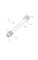
次に図8を参照して供給側ボビン34について説明する。図8は供給側ボビンの斜視図である。  Next, the supply-side bobbin 34 will be described with reference to FIG. FIG. 8 is a perspective view of the supply side bobbin.

供給側ボビン34はインクリボン31を巻回する軸部36を構成し、軸部36の両端に当接部39a、39bを構成している。また軸部36の一端に回転規制穴38が軸全周に渡り設けられている。また供給側ボビン34の端には突起部37が備えられており、前述したプリンタ本体1内に構成された第一のボビン軸15の爪部16によって回転動作が付与される構成となっている。  The supply-side bobbin 34 forms ashaft portion 36 around which theink ribbon 31 is wound, andcontact portions 39 a and 39 b are formed at both ends of theshaft portion 36. Arotation restricting hole 38 is provided at one end of theshaft portion 36 over the entire circumference of the shaft. Further, aprotrusion 37 is provided at the end of the supply-side bobbin 34 and is configured to be rotated by theclaw 16 of thefirst bobbin shaft 15 configured in the printer main body 1 described above. .

また本実施例では巻取り側ボビン35が供給側ボビン34と同構成となっている。供給側ボビン34、巻取り側ボビン35はそれぞれ前述した第一のコイルばね90、第二のコイルばね91を端部33に備えることによって、前述した筺体部材50の開口部42a、42b側に付勢される構成となっている。  In this embodiment, the take-upbobbin 35 has the same configuration as the supply-side bobbin 34. The supply-side bobbin 34 and the take-up-side bobbin 35 are attached to the openings 42a and 42b of thehousing member 50 described above by providing theend coil 33 with thefirst coil spring 90 and thesecond coil spring 91 described above, respectively. It is the composition which is energized.

次に図9を参照して移動部材70について説明する。図9は移動部材の斜視図である。  Next, the movingmember 70 will be described with reference to FIG. FIG. 9 is a perspective view of the moving member.

移動部材70は移動可能な構成となっており、両端にカム面71a、71bを構成している。また中央付近にはリブ部72a、72b、72c、72dが構成されており、前述した第一の蓋部材50の開口部51a、51b、51c、51dにそれぞれ対応し収納される。本実施例ではリブ部を72a、72b、72c、72dは支持部76の両端付近にそれぞれ2つずつ配置されている。またこのリブ部72の位置は、前述した用紙10のサイズに対応して設置されている。すなわち、リブ部72b、72cは4inchサイズの用紙10の紙幅より内側の位置に配置され、そして最両端のリブ部72a、72dは5inchサイズの用紙10の紙幅より内側の位置に配置される構成となっている。また移動部材70のリブ部72の形状は、用紙10搬送方向に対して滑らかな曲部77に形成されており、対して用紙10搬送方向とは逆方向には返し形状となる突起部75が構成されている。また移動部材70の両端付近にはばね掛け部73a、73bが構成されており、前述した第一のばね93のフック部93bと第二のばね96のフック部96bを引掛ける構成となっている。さらに移動部材70の一端には回転規制部74が構成されており、供給側ボビン34に設けられた回転規制穴38に対応している。  The movingmember 70 is configured to be movable, andcam surfaces 71a and 71b are formed at both ends. Further,rib portions 72a, 72b, 72c, 72d are formed near the center, and are accommodated corresponding to theopenings 51a, 51b, 51c, 51d of thefirst lid member 50 described above, respectively. In the present embodiment, tworib portions 72 a, 72 b, 72 c, 72 d are disposed near both ends of thesupport portion 76. The position of therib portion 72 is set corresponding to the size of thepaper 10 described above. That is, therib portions 72b and 72c are arranged at positions inside the paper width of the 4-inch size paper 10, and therib portions 72a and 72d at the extreme ends are arranged at positions inside the paper width of the 5-inch size paper 10. It has become. In addition, therib portion 72 of the movingmember 70 is formed in acurved portion 77 that is smooth with respect to thepaper 10 conveyance direction, and aprotrusion 75 that has a return shape in the direction opposite to thepaper 10 conveyance direction. It is configured. Further,spring hooking portions 73a and 73b are formed near both ends of the movingmember 70, and the hook portion 93b of the first spring 93 and thehook portion 96b of thesecond spring 96 are hooked. . Further, arotation restricting portion 74 is formed at one end of the movingmember 70 and corresponds to therotation restricting hole 38 provided in thesupply side bobbin 34.

次にインクリボンカセット30の移動部材70の動作について図10〜図12を参照して説明する。  Next, the operation of the movingmember 70 of theink ribbon cassette 30 will be described with reference to FIGS.

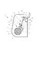
図10はプリンタ本体に装填前のインクリボンカセットの断面図である。  FIG. 10 is a cross-sectional view of the ink ribbon cassette before being loaded into the printer body.

インクリボンカセット30はプリンタ本体1に装填前においては、前述した構成により、第一のコイルばね90と第二のコイルばね91によって、供給側ボビン34と巻取り側ボビン35は図10中矢印B方向に付勢されている。このとき第一のばね95と第二のばね96の弾性力によって移動部材70は、図10中矢印E方向に付勢されており、移動部材70に構成されたリブ部72a、72b、72c、72dは第一の蓋部材50の表面より内側に収納される構成となっている。さらに移動部材70に構成された回転規制部74が供給側ボビン34に構成された回転規制穴38に係合されることによって供給側ボビン34の回転を規制している。  Before theink ribbon cassette 30 is loaded into the printer main body 1, the supply-side bobbin 34 and the take-upbobbin 35 are moved in the direction indicated by the arrow B in FIG. 10 by thefirst coil spring 90 and thesecond coil spring 91. Is being energized. At this time, the movingmember 70 is urged in the direction of arrow E in FIG. 10 by the elastic force of thefirst spring 95 and thesecond spring 96, andribs 72a, 72b, 72c formed on the movingmember 70, 72 d is configured to be housed inside the surface of thefirst lid member 50. Further, therotation restricting portion 74 formed on the movingmember 70 is engaged with therotation restricting hole 38 formed on thesupply side bobbin 34 to restrict the rotation of thesupply side bobbin 34.

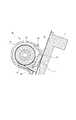
図11はプリンタ本体に装填後のインクリボンカセットの断面図である。  FIG. 11 is a cross-sectional view of the ink ribbon cassette after being loaded into the printer body.

インクリボンカセット30をプリンタ本体1への装着が完了すると、前述のプリンタ本体1に構成された第一のボビン軸15と第二のボビン軸17が供給側ボビン34と巻取り側ボビン35を押し込み、図11中矢印C方向に移動する。このとき、移動部材70のカム面71a、71bが供給側ボビン34の当接部39によって押し込まれ、図11中矢印D方向に移動する。この移動部材70の動作により移動部材70の回転規制部74が供給側ボビン34の回転規制穴38から外れ、供給側ボビン34は回動自由状態になる。さらに当接部39の径の大きさを移動部材70のカム面71が乗り上げた状態で第一の蓋部材70の表面からリブ部72a、72b、72c、72dが突出するように設定する事で、リブ部72がインクリボンカセット30から外側に露出する構成となっている。  When the mounting of theink ribbon cassette 30 to the printer main body 1 is completed, thefirst bobbin shaft 15 and thesecond bobbin shaft 17 configured in the printer main body 1 push in thesupply side bobbin 34 and the take-upside bobbin 35, It moves in the direction of arrow C in FIG. At this time, the cam surfaces 71a and 71b of the movingmember 70 are pushed in by the contact portion 39 of the supply-side bobbin 34 and move in the direction of arrow D in FIG. Due to the operation of the movingmember 70, therotation restricting portion 74 of the movingmember 70 is removed from therotation restricting hole 38 of thesupply side bobbin 34, and thesupply side bobbin 34 is in a freely rotatable state. Further, the diameter of the contact portion 39 is set so that therib portions 72a, 72b, 72c, 72d protrude from the surface of thefirst lid member 70 in a state where the cam surface 71 of the movingmember 70 rides on. Therib portion 72 is exposed from theink ribbon cassette 30 to the outside.

本構成によってインクリボンカセット30がプリンタ本体1に装填されていない際にはリブ部72は、インクリボンカセット30内に収納されることにより、ユーザーはリブ部72に触れることが出来ない為、手油等の汚れが付着する事を防止できる。  With this configuration, when theink ribbon cassette 30 is not loaded in the printer main body 1, therib portion 72 is housed in theink ribbon cassette 30 so that the user cannot touch therib portion 72. It is possible to prevent the dirt from adhering.

なお、図10中矢印B方向は、図11中矢印C方向と逆の方向であり、図10中矢印E方向は、図11中矢印D方向と逆方向である。また、図11中矢印D方向と図11中矢印C方向は、略直交する方向である。移動部材70が、カム面71を有していることにより、供給側ボビン34が移動したときに、供給側ボビン34がカム面に当接して、移動部材70が供給側ボビン34の移動方向とは直交する方向に移動するような構成になっている。  In addition, the arrow B direction in FIG. 10 is a direction opposite to the arrow C direction in FIG. 11, and the arrow E direction in FIG. 10 is the opposite direction to the arrow D direction in FIG. Further, the direction of arrow D in FIG. 11 and the direction of arrow C in FIG. 11 are substantially orthogonal directions. Since the movingmember 70 has the cam surface 71, when the supply-side bobbin 34 moves, the supply-side bobbin 34 comes into contact with the cam surface, and the movingmember 70 moves in the moving direction of the supply-side bobbin 34. Is configured to move in the orthogonal direction.

図12は移動部材の印刷時の断面図である。  FIG. 12 is a cross-sectional view of the moving member during printing.

移動部材70のリブ部72が第一の蓋部材50の表面より外側に露出することにより、印刷時の用紙10は搬送中に第一の蓋部材50に触れることなくリブ部72と用紙ガイド14との間を通紙される。本実施例においてはリブ部72と用紙ガイド14の用紙10が通紙する隙間は用紙10の厚みの1.5倍程度となるように移動部材70の移動量を設定している。本構成により、用紙10がリブ部72と用紙ガイド14間を排紙方向に通紙の際には、上述したリブ部72に構成された曲部77によって、引っかかりが発生せずに通紙される。また、印刷の不具合動作によって印画物10aや切り屑10bがプリンタ本体1内に侵入した際においても、上述したリブ部72に構成された突起部75によって、印刷機構内部へ侵入を防ぐことが出来る。  Since therib portion 72 of the movingmember 70 is exposed outside the surface of thefirst lid member 50, thepaper 10 during printing does not touch thefirst lid member 50 during conveyance, and therib portion 72 and thepaper guide 14. Paper is passed between. In this embodiment, the moving amount of the movingmember 70 is set so that the gap between therib portion 72 and thepaper guide 14 through which thepaper 10 passes is about 1.5 times the thickness of thepaper 10. With this configuration, when thepaper 10 is passed between therib portion 72 and thepaper guide 14 in the paper discharge direction, thepaper 10 is passed without being caught by thecurved portion 77 formed in therib portion 72 described above. The Further, even when the printedmatter 10a or thechips 10b enter the printer main body 1 due to a printing malfunction, theprotrusions 75 formed on theribs 72 described above can prevent the inside of the printing mechanism from entering. .

本実施例では、供給側ボビン34側の筺体を構成するボビン軸と略平行な面に、リブ部が突出可能な構成とした。供給側ボビン34側は、インクリボンと用紙を重ねた状態で搬送させる必要があるが、印刷後は、インクリボンは用紙とくっつかないように引き離されて搬送されるため、巻き取り側ボビンが収納されている側の筺体には、用紙が接触しないためである。しかし、巻き取り側ボビンが収納されている側の筺体に用紙が接触しながら搬送される場合には、巻き取り側ボビンが収納されている側の筺体にも、リブ部が突出可能な構成を設けてもよい。  In the present embodiment, the rib portion can be projected on a surface substantially parallel to the bobbin shaft constituting the housing on thesupply side bobbin 34 side. The supply-side bobbin 34 side needs to be transported with the ink ribbon and paper stacked, but after printing, the ink ribbon is transported away from the paper so that it does not stick to the paper. This is because the paper does not come into contact with the housing on the side where the paper is provided. However, when the paper is conveyed while contacting the casing on the side where the winding side bobbin is stored, the rib part can also protrude from the casing on the side where the winding side bobbin is stored. It may be provided.

以上、本発明をその好適な実施形態に基づいて詳述してきたが、本発明はこれら特定の実施形態に限られるものではなく、この発明の要旨を逸脱しない範囲の様々な形態も本発明に含まれる。  Although the present invention has been described in detail based on preferred embodiments thereof, the present invention is not limited to these specific embodiments, and various forms within the scope of the present invention are also included in the present invention. included.

1 プリンタ本体
2 筺体
10 用紙
14 用紙ガイド部材
15 第一のボビン軸
16 爪部
17 第二のボビン軸
18 爪部
30 インクリボンカセット
31 インクリボン
34 供給側ボビン
35 巻取り側ボビン
36 軸部
37 突起部
38 回転規制穴
39 当接部
40 筺体部材
46 ばね掛け部
50 第一の蓋部材
51 開口部
60 第二の蓋部材
70 移動部材
71 カム面
72 リブ部
73 ばね掛け部
74 回転規制部
75 突起部
76 支持部
77 曲部
95 第一のばね
96 第二のばね
DESCRIPTION OF SYMBOLS 1 Printermain body 2 Housing | casing 10Paper 14Paper guide member 15 1st bobbin axis |shaft 16Claw part 17 2nd bobbin axis |shaft 18Claw part 30Ink ribbon cassette 31Ink ribbon 34Supply side bobbin 35Winding side bobbin 36Shaft part 37Protrusion part 38 Rotation Restriction Hole 39Abutting Portion 40 Housing Member 46Spring Hanging Portion 50 First Lid Member 51Opening Portion 60Second Lid Member 70 Moving Member 71Cam Surface 72 Rib Portion 73Spring Hanging Portion 74Rotation Restricting Portion 75Projection Portion 76Supporting part 77Curved part 95First spring 96 Second spring

Claims (7)

Translated fromJapanese
インクリボンのインクを用紙に転写する印刷装置に着脱可能な、インクリボンを収納するインクリボンカセットであって、
前記印刷装置に装着されていないときは、前記インクリボンカセット内に収納され、前記印刷装置に装着されているときには、前記インクリボンカセットの筺体から突出して用紙をガイドするリブ部を有することを特徴とするインクリボンカセット。
An ink ribbon cassette that accommodates an ink ribbon that can be attached to and detached from a printing device that transfers ink from an ink ribbon onto paper,
When not installed in the printing apparatus, the apparatus is housed in the ink ribbon cassette, and when installed in the printing apparatus, the apparatus has a rib portion that protrudes from the casing of the ink ribbon cassette and guides paper. Ink ribbon cassette.
前記リブ部は、前記インクリボンカセットが前記印刷装置に装着されたことに応じて、前記インクリボンカセットの筺体から突出した位置に移動することを特徴とする請求項1に記載のインクリボンカセット。  The ink ribbon cassette according to claim 1, wherein the rib portion moves to a position protruding from a housing of the ink ribbon cassette in response to the ink ribbon cassette being mounted on the printing apparatus. 前記印刷装置に装着されていないときは、前記リブ部の用紙をガイドする際に用紙に接触する面が、前記インクリボンカセット筺体の表面よりも内側に収納されることを特徴とする請求項1または2に記載のインクリボンカセット。  The surface of the rib portion that comes into contact with the paper when guiding the paper in the rib portion is housed inside the surface of the ink ribbon cassette housing when not mounted in the printing apparatus. The ink ribbon cassette according to 2. 前記インクリボンカセットは、
インクリボンが巻きつけられたボビンと、
前記ボビンを内部に収納する筐体と、
前記ボビンを前記筺体内においてボビンの軸方向と平行な第一の方向に付勢するボビン付勢部材と、
前記リブ部が設けられた移動部材であって、前記リブ部が前記筺体内に収納される第一の位置と、前記リブ部が前記筺体の外に突出する第二の位置に移動可能な移動部材と、
前記移動部材を前記第一の位置側に付勢する付勢部材と、を備え、
前記インクリボンカセットが前記印刷装置に装着されたことに応じて、前記印刷装置内に設けられた前記ボビンを回動させるための軸部材に当接することにより、前記ボビンが前記第一の方向とは逆の第二の方向に移動し、当該ボビンが第二の方向に移動したことに応じて、前記移動部材が前記第二の位置に移動することを特徴とする請求項1ないし3のいずれか一項に記載のインクリボンカセット。
The ink ribbon cassette is
A bobbin wrapped with an ink ribbon,
A housing that houses the bobbin therein;
A bobbin urging member that urges the bobbin in a first direction parallel to the axial direction of the bobbin in the housing;
A moving member provided with the rib portion, wherein the rib portion is movable to a first position where the rib portion is housed in the housing, and a second position where the rib portion protrudes outside the housing. Members,
A biasing member that biases the moving member toward the first position,
When the ink ribbon cassette is attached to the printing apparatus, the bobbin is brought into contact with a shaft member for rotating the bobbin provided in the printing apparatus so that the bobbin is in the first direction. 4. The apparatus according to claim 1, wherein the moving member moves to the second position in response to movement in the opposite second direction and the bobbin moving in the second direction. 5. The ink ribbon cassette according to one item.
前記リブは、前記第1の方向に平行な前記筺体の面から突出可能なように設けられており、
前記付勢部材は、前記第1の方向と略直交する方向に前記移動部材を付勢していることを特徴とする請求項4に記載のインクリボンカセット。
The rib is provided so as to protrude from a surface of the housing parallel to the first direction,
The ink ribbon cassette according to claim 4, wherein the urging member urges the moving member in a direction substantially orthogonal to the first direction.
前記ボビンが前記第二の方向に移動したことに応じて、前記移動部材は、前記第二の方向と略直交する方向に移動することを特徴とする請求項4または5に記載のインクリボンカセット。  6. The ink ribbon cassette according to claim 4, wherein the moving member moves in a direction substantially orthogonal to the second direction in response to the bobbin moving in the second direction. 前記移動部材は、カム面を有し、
前記第二の方向に移動する前記ボビンが、前記カム面に当接することにより、前記移動部材が、前記第二の方向と略直交する方向に移動することを特徴とする請求項4ないし6のいずれか1項に記載のインクリボンカセット。
The moving member has a cam surface;
7. The bobbin that moves in the second direction abuts on the cam surface, so that the moving member moves in a direction substantially perpendicular to the second direction. The ink ribbon cassette according to any one of the above.
JP2011260905A2011-11-292011-11-29Ink ribbon cassettePendingJP2013111879A (en)

Priority Applications (1)

Application NumberPriority DateFiling DateTitle
JP2011260905AJP2013111879A (en)2011-11-292011-11-29Ink ribbon cassette

Applications Claiming Priority (1)

Application NumberPriority DateFiling DateTitle
JP2011260905AJP2013111879A (en)2011-11-292011-11-29Ink ribbon cassette

Publications (1)

Publication NumberPublication Date
JP2013111879Atrue JP2013111879A (en)2013-06-10

Family

ID=48707923

Family Applications (1)

Application NumberTitlePriority DateFiling Date
JP2011260905APendingJP2013111879A (en)2011-11-292011-11-29Ink ribbon cassette

Country Status (1)

CountryLink
JP (1)JP2013111879A (en)

Cited By (1)

* Cited by examiner, † Cited by third party
Publication numberPriority datePublication dateAssigneeTitle
WO2022118388A1 (en)*2020-12-022022-06-09三菱電機株式会社Printer and ink cassette for printer

Cited By (1)

* Cited by examiner, † Cited by third party
Publication numberPriority datePublication dateAssigneeTitle
WO2022118388A1 (en)*2020-12-022022-06-09三菱電機株式会社Printer and ink cassette for printer

Similar Documents

PublicationPublication DateTitle
US8827440B2 (en)Printer
EP1798050B1 (en)Paper roll feed mechanism and image forming apparatus
CN1663807B (en) tape supply box
US5378072A (en)Transfer materials supplier
JPH07329385A (en)Ink film cassette
JP6666497B1 (en) Printer
JP2014046606A (en)Thermal transfer printer
JP2013111879A (en)Ink ribbon cassette
JP2006306511A (en)Rolled sheet cue mechanism, paper feeding cassette and printer
JP2014083828A (en)Printer
JPH09123574A (en)Ink film cassette
JP2022072933A (en) cassette
JP4424156B2 (en) Printer
JP5562148B2 (en) Recording device
JP4561673B2 (en) Printing device
JP2016193570A (en)Cassette head cleaner and thermal transfer printer
JP7505369B2 (en) Printing device
JP6644925B1 (en) Printer
JP4363284B2 (en) Printer
JP2002273994A (en)Integral cartridge for recording sheet and thermal recording ribbon
JP4613775B2 (en) Printing device
JPH07329372A (en)Recorder
JP2010076168A (en)Tape printer
JP2004167878A (en)Core material of rolled paper sheet for printer
JPH08300703A (en)Thermal ink-transfer recording apparatus

[8]ページ先頭

©2009-2025 Movatter.jp