JP2013106952A - Medical device control handle - Google Patents
Medical device control handleDownload PDFInfo
- Publication number
- JP2013106952A JP2013106952AJP2012251984AJP2012251984AJP2013106952AJP 2013106952 AJP2013106952 AJP 2013106952AJP 2012251984 AJP2012251984 AJP 2012251984AJP 2012251984 AJP2012251984 AJP 2012251984AJP 2013106952 AJP2013106952 AJP 2013106952A
- Authority
- JP
- Japan
- Prior art keywords
- washer
- control handle
- shaft body
- dial
- actuator assembly
- Prior art date
- Legal status (The legal status is an assumption and is not a legal conclusion. Google has not performed a legal analysis and makes no representation as to the accuracy of the status listed.)
- Granted
Links
- 230000001939inductive effectEffects0.000claimsdescription15
- 238000000034methodMethods0.000claimsdescription4
- 238000012546transferMethods0.000abstractdescription2
- 230000006835compressionEffects0.000description26
- 238000007906compressionMethods0.000description26
- 230000008602contractionEffects0.000description20
- 239000000835fiberSubstances0.000description16
- 239000000853adhesiveSubstances0.000description15
- 230000001070adhesive effectEffects0.000description15
- 238000013507mappingMethods0.000description14
- 239000000463materialSubstances0.000description13
- 230000002093peripheral effectEffects0.000description12
- 239000004642PolyimideSubstances0.000description9
- 229920001721polyimidePolymers0.000description9
- 229920002635polyurethanePolymers0.000description6
- 239000004814polyurethaneSubstances0.000description6
- 229910001220stainless steelInorganic materials0.000description6
- 239000010935stainless steelSubstances0.000description6
- 230000000694effectsEffects0.000description5
- 210000003492pulmonary veinAnatomy0.000description5
- 230000001965increasing effectEffects0.000description4
- WABPQHHGFIMREM-UHFFFAOYSA-Nlead(0)Chemical compound[Pb]WABPQHHGFIMREM-UHFFFAOYSA-N0.000description4
- 230000007246mechanismEffects0.000description4
- 229920006362Teflon®Polymers0.000description3
- 239000002184metalSubstances0.000description3
- 230000007935neutral effectEffects0.000description3
- 239000004033plasticSubstances0.000description3
- 229920003023plasticPolymers0.000description3
- 230000001681protective effectEffects0.000description3
- 230000003068static effectEffects0.000description3
- 239000004677NylonSubstances0.000description2
- 229920000508VectranPolymers0.000description2
- 239000004979VectranSubstances0.000description2
- 238000002679ablationMethods0.000description2
- 230000002159abnormal effectEffects0.000description2
- 230000000712assemblyEffects0.000description2
- 238000000429assemblyMethods0.000description2
- 230000001746atrial effectEffects0.000description2
- 238000005452bendingMethods0.000description2
- 239000011248coating agentSubstances0.000description2
- 238000000576coating methodMethods0.000description2
- 230000008878couplingEffects0.000description2
- 238000010168coupling processMethods0.000description2
- 238000005859coupling reactionMethods0.000description2
- -1for exampleSubstances0.000description2
- 230000006870functionEffects0.000description2
- 230000013011matingEffects0.000description2
- 238000005259measurementMethods0.000description2
- 229920001778nylonPolymers0.000description2
- 229920000642polymerPolymers0.000description2
- 230000002459sustained effectEffects0.000description2
- 206010003658Atrial FibrillationDiseases0.000description1
- 229920001651CyanoacrylatePolymers0.000description1
- 239000004819Drying adhesiveSubstances0.000description1
- 206010015856ExtrasystolesDiseases0.000description1
- 229920000271Kevlar®Polymers0.000description1
- 229920000106Liquid crystal polymerPolymers0.000description1
- 239000004977Liquid-crystal polymers (LCPs)Substances0.000description1
- 239000004830Super GlueSubstances0.000description1
- 241000219793TrifoliumSpecies0.000description1
- 229920003235aromatic polyamidePolymers0.000description1
- 206010003119arrhythmiaDiseases0.000description1
- 210000001367arteryAnatomy0.000description1
- 230000000903blocking effectEffects0.000description1
- 238000009954braidingMethods0.000description1
- 239000004918carbon fiber reinforced polymerSubstances0.000description1
- 239000000919ceramicSubstances0.000description1
- 150000001875compoundsChemical class0.000description1
- 238000010276constructionMethods0.000description1
- 230000003247decreasing effectEffects0.000description1
- 238000013461designMethods0.000description1
- 229910003460diamondInorganic materials0.000description1
- 239000010432diamondSubstances0.000description1
- 238000001035dryingMethods0.000description1
- 230000007831electrophysiologyEffects0.000description1
- 238000002001electrophysiologyMethods0.000description1
- 210000001105femoral arteryAnatomy0.000description1
- 239000003365glass fiberSubstances0.000description1
- 210000002837heart atriumAnatomy0.000description1
- 229920001903high density polyethylenePolymers0.000description1
- 239000004700high-density polyethyleneSubstances0.000description1
- 239000004761kevlarSubstances0.000description1
- 239000011159matrix materialSubstances0.000description1
- 230000001404mediated effectEffects0.000description1
- 238000012986modificationMethods0.000description1
- 230000004048modificationEffects0.000description1
- 238000000465mouldingMethods0.000description1
- HLXZNVUGXRDIFK-UHFFFAOYSA-Nnickel titaniumChemical compound[Ti].[Ti].[Ti].[Ti].[Ti].[Ti].[Ti].[Ti].[Ti].[Ti].[Ti].[Ni].[Ni].[Ni].[Ni].[Ni].[Ni].[Ni].[Ni].[Ni].[Ni].[Ni].[Ni].[Ni].[Ni]HLXZNVUGXRDIFK-UHFFFAOYSA-N0.000description1
- 229910001000nickel titaniumInorganic materials0.000description1
- 239000000615nonconductorSubstances0.000description1
- 231100000252nontoxicToxicity0.000description1
- 230000003000nontoxic effectEffects0.000description1
- 230000002085persistent effectEffects0.000description1
- 230000008569processEffects0.000description1
- 230000004043responsivenessEffects0.000description1
- 238000001228spectrumMethods0.000description1
- 239000003351stiffenerSubstances0.000description1
- 229920000785ultra high molecular weight polyethylenePolymers0.000description1
- 210000003462veinAnatomy0.000description1
- 210000001631vena cava inferiorAnatomy0.000description1
- 210000002620vena cava superiorAnatomy0.000description1
- 230000000007visual effectEffects0.000description1
Images


Classifications
- A—HUMAN NECESSITIES
- A61—MEDICAL OR VETERINARY SCIENCE; HYGIENE
- A61B—DIAGNOSIS; SURGERY; IDENTIFICATION
- A61B17/00—Surgical instruments, devices or methods
- A—HUMAN NECESSITIES
- A61—MEDICAL OR VETERINARY SCIENCE; HYGIENE
- A61M—DEVICES FOR INTRODUCING MEDIA INTO, OR ONTO, THE BODY; DEVICES FOR TRANSDUCING BODY MEDIA OR FOR TAKING MEDIA FROM THE BODY; DEVICES FOR PRODUCING OR ENDING SLEEP OR STUPOR
- A61M25/00—Catheters; Hollow probes
- A61M25/01—Introducing, guiding, advancing, emplacing or holding catheters
- A61M25/09—Guide wires
- A—HUMAN NECESSITIES
- A61—MEDICAL OR VETERINARY SCIENCE; HYGIENE
- A61M—DEVICES FOR INTRODUCING MEDIA INTO, OR ONTO, THE BODY; DEVICES FOR TRANSDUCING BODY MEDIA OR FOR TAKING MEDIA FROM THE BODY; DEVICES FOR PRODUCING OR ENDING SLEEP OR STUPOR
- A61M25/00—Catheters; Hollow probes
- A61M25/01—Introducing, guiding, advancing, emplacing or holding catheters
- A61M25/0105—Steering means as part of the catheter or advancing means; Markers for positioning
- A61M25/0133—Tip steering devices
- A61M25/0136—Handles therefor
- A—HUMAN NECESSITIES
- A61—MEDICAL OR VETERINARY SCIENCE; HYGIENE
- A61M—DEVICES FOR INTRODUCING MEDIA INTO, OR ONTO, THE BODY; DEVICES FOR TRANSDUCING BODY MEDIA OR FOR TAKING MEDIA FROM THE BODY; DEVICES FOR PRODUCING OR ENDING SLEEP OR STUPOR
- A61M25/00—Catheters; Hollow probes
- A—HUMAN NECESSITIES
- A61—MEDICAL OR VETERINARY SCIENCE; HYGIENE
- A61M—DEVICES FOR INTRODUCING MEDIA INTO, OR ONTO, THE BODY; DEVICES FOR TRANSDUCING BODY MEDIA OR FOR TAKING MEDIA FROM THE BODY; DEVICES FOR PRODUCING OR ENDING SLEEP OR STUPOR
- A61M25/00—Catheters; Hollow probes
- A61M25/01—Introducing, guiding, advancing, emplacing or holding catheters
- A61M25/0105—Steering means as part of the catheter or advancing means; Markers for positioning
- A61M25/0133—Tip steering devices
- A61M25/0147—Tip steering devices with movable mechanical means, e.g. pull wires
- A—HUMAN NECESSITIES
- A61—MEDICAL OR VETERINARY SCIENCE; HYGIENE
- A61B—DIAGNOSIS; SURGERY; IDENTIFICATION
- A61B18/00—Surgical instruments, devices or methods for transferring non-mechanical forms of energy to or from the body
- A61B18/04—Surgical instruments, devices or methods for transferring non-mechanical forms of energy to or from the body by heating
- A61B18/12—Surgical instruments, devices or methods for transferring non-mechanical forms of energy to or from the body by heating by passing a current through the tissue to be heated, e.g. high-frequency current
- A61B18/14—Probes or electrodes therefor
- A61B18/1492—Probes or electrodes therefor having a flexible, catheter-like structure, e.g. for heart ablation
- A—HUMAN NECESSITIES
- A61—MEDICAL OR VETERINARY SCIENCE; HYGIENE
- A61B—DIAGNOSIS; SURGERY; IDENTIFICATION
- A61B17/00—Surgical instruments, devices or methods
- A61B17/00234—Surgical instruments, devices or methods for minimally invasive surgery
- A61B2017/00292—Surgical instruments, devices or methods for minimally invasive surgery mounted on or guided by flexible, e.g. catheter-like, means
- A61B2017/003—Steerable
- A61B2017/00318—Steering mechanisms
- A61B2017/00323—Cables or rods
- A61B2017/00327—Cables or rods with actuating members moving in opposite directions
- A—HUMAN NECESSITIES
- A61—MEDICAL OR VETERINARY SCIENCE; HYGIENE
- A61B—DIAGNOSIS; SURGERY; IDENTIFICATION
- A61B18/00—Surgical instruments, devices or methods for transferring non-mechanical forms of energy to or from the body
- A61B2018/00636—Sensing and controlling the application of energy
- A61B2018/00773—Sensed parameters
- A61B2018/00839—Bioelectrical parameters, e.g. ECG, EEG
- A—HUMAN NECESSITIES
- A61—MEDICAL OR VETERINARY SCIENCE; HYGIENE
- A61B—DIAGNOSIS; SURGERY; IDENTIFICATION
- A61B18/00—Surgical instruments, devices or methods for transferring non-mechanical forms of energy to or from the body
- A61B2018/0091—Handpieces of the surgical instrument or device
- A—HUMAN NECESSITIES
- A61—MEDICAL OR VETERINARY SCIENCE; HYGIENE
- A61B—DIAGNOSIS; SURGERY; IDENTIFICATION
- A61B18/00—Surgical instruments, devices or methods for transferring non-mechanical forms of energy to or from the body
- A61B18/04—Surgical instruments, devices or methods for transferring non-mechanical forms of energy to or from the body by heating
- A61B18/12—Surgical instruments, devices or methods for transferring non-mechanical forms of energy to or from the body by heating by passing a current through the tissue to be heated, e.g. high-frequency current
- A61B18/14—Probes or electrodes therefor
- A61B2018/1405—Electrodes having a specific shape
- A61B2018/1435—Spiral
- A—HUMAN NECESSITIES
- A61—MEDICAL OR VETERINARY SCIENCE; HYGIENE
- A61M—DEVICES FOR INTRODUCING MEDIA INTO, OR ONTO, THE BODY; DEVICES FOR TRANSDUCING BODY MEDIA OR FOR TAKING MEDIA FROM THE BODY; DEVICES FOR PRODUCING OR ENDING SLEEP OR STUPOR
- A61M25/00—Catheters; Hollow probes
- A61M25/01—Introducing, guiding, advancing, emplacing or holding catheters
- A61M25/09—Guide wires
- A61M2025/09116—Design of handles or shafts or gripping surfaces thereof for manipulating guide wires
Landscapes
- Health & Medical Sciences (AREA)
- Life Sciences & Earth Sciences (AREA)
- Engineering & Computer Science (AREA)
- Animal Behavior & Ethology (AREA)
- Veterinary Medicine (AREA)
- Public Health (AREA)
- Biomedical Technology (AREA)
- Heart & Thoracic Surgery (AREA)
- General Health & Medical Sciences (AREA)
- Anesthesiology (AREA)
- Hematology (AREA)
- Pulmonology (AREA)
- Biophysics (AREA)
- Mechanical Engineering (AREA)
- Surgery (AREA)
- Nuclear Medicine, Radiotherapy & Molecular Imaging (AREA)
- Medical Informatics (AREA)
- Molecular Biology (AREA)
- Media Introduction/Drainage Providing Device (AREA)
- Surgical Instruments (AREA)
Abstract
Translated fromJapaneseDescription
Translated fromJapanese本発明は医療機器の制御ハンドルに関するものであり、特に、医療機器の異なる機能を別々に操作する複数の牽引ワイヤを制御するためのメカニズムを有する制御ハンドルに関する。 The present invention relates to a control handle for a medical device, and more particularly to a control handle having a mechanism for controlling a plurality of pull wires that operate different functions of the medical device separately.
電極カテーテルは、長年にわたり医療行為で一般的に用いられている。電極カテーテルは心臓内の電気的活動を刺激及びマッピングし、異常な電気的活動が見られる部位を切除するために用いられる。心房細動は、一般的な持続性心不整脈であり、脳卒中の主な原因である。この病状は、異常な心房組織基質内で伝播するリエントラント型ウェーブレットによって持続される。ウェーブレット遮断するため、様々な方法が開発されており、外科的又はカテーテル媒介心房切開が含まれる。病状を治療する前に、まず、ウェーブレットの位置を判定しなければならない。そのような判定を行うために、様々な技術が提案されており、構造の内周周囲の肺静脈、環状静脈洞、又は他の管状構造内の活性を測定するように適合されたマッピングアセンブリを備えるカテーテルの使用が含まれる。1つのそのようなマッピングアセンブリは、カテーテル本体を概ね横断し、その遠位にある、概ね円形の主要領域を備え、外周及び主要領域の遠位にある概ね線状の遠位領域を有する、管状構造を有する。管状構造は、少なくともマッピングアセンブリの主要領域上に非導電性カバーを備える。形状記憶を有する支持部材は、少なくともマッピングアセンブリの主要領域内に配置される。複数の電極対(それぞれ2つの環電極を含む)は、マッピングアセンブリの概ね円形の主要領域によって担持される。 Electrode catheters have been commonly used in medical practice for many years. Electrode catheters are used to stimulate and map electrical activity in the heart and to excise sites where abnormal electrical activity is seen. Atrial fibrillation is a common persistent cardiac arrhythmia and is a major cause of stroke. This condition is sustained by reentrant wavelets that propagate within the abnormal atrial tissue matrix. Various methods have been developed for wavelet blocking, including surgical or catheter-mediated atrial incisions. Before treating a medical condition, the position of the wavelet must first be determined. In order to make such a determination, various techniques have been proposed, including mapping assemblies adapted to measure activity in the pulmonary veins, annular sinuses, or other tubular structures around the inner periphery of the structure. The use of a catheter with is included. One such mapping assembly is tubular having a generally circular main region generally transverse to and distal of the catheter body and having a generally linear distal region distal to the outer periphery and the main region. It has a structure. The tubular structure comprises a non-conductive cover at least on the main area of the mapping assembly. A support member having shape memory is disposed at least in the main region of the mapping assembly. A plurality of electrode pairs (each including two ring electrodes) are carried by the generally circular main region of the mapping assembly.
使用中、電極カテーテルは、主要静脈又は動脈、例えば、大腿動脈に位置付けられている誘導シース内に挿入され、かつ心室内に誘導される。心室内で、カテーテルは、誘導シースの遠位端を越えて延び、マッピングアセンブリを露出させる。カテーテルは、マッピングアセンブリが心室の管状領域に位置付けられるように、カテーテルの遠位部分の偏向を含む動作を介して操作される。カテーテルの正確な位置及び配向、並びにマッピングアセンブリの構成を制御する能力は、非常に重要であり、カテーテルの有用性が主にこれにより決まる。 In use, the electrode catheter is inserted into a guiding sheath positioned in the main vein or artery, eg, the femoral artery, and guided into the ventricle. Within the ventricle, the catheter extends beyond the distal end of the guide sheath to expose the mapping assembly. The catheter is manipulated through operations that include deflection of the distal portion of the catheter such that the mapping assembly is positioned in the tubular region of the ventricle. The exact position and orientation of the catheter and the ability to control the configuration of the mapping assembly is very important and mainly determines the usefulness of the catheter.
可動型カテーテルは、一般的に周知である。例えば、米国特許第Re 34,502号は、その遠位端にピストンチャンバを有するハウジングを備える、制御ハンドルを有するカテーテルについて記述している。ピストンは、ピストンチャンバ内に載置され、縦方向移動が与えられる。細長いカテーテル本体の近位端は、ピストンに取り付けられる。牽引ワイヤは、ハウジングに取り付けられ、ピストンを通り、カテーテル本体を通り、かつカテーテル本体の遠位端の先端部分内に延びる。牽引ワイヤの遠位端は、カテーテルの先端部分内に固定される。この配置では、ハウジングに対するピストンの縦方向動作は、カテーテルの先端部分の偏向をもたらす。 Movable catheters are generally well known. For example, US Pat. No. Re 34,502 describes a catheter having a control handle with a housing having a piston chamber at its distal end. The piston is mounted in the piston chamber and is given longitudinal movement. The proximal end of the elongate catheter body is attached to the piston. A puller wire is attached to the housing and extends through the piston, through the catheter body, and into the tip portion of the distal end of the catheter body. The distal end of the puller wire is secured within the tip portion of the catheter. In this arrangement, longitudinal movement of the piston relative to the housing results in deflection of the catheter tip.
米国再発行特許第RE 34,502号に説明される設計は、一般的に、単一の牽引ワイヤを有するカテーテルに制限される。2方向の偏向が望ましい場合、1本以上の牽引ワイヤが必要になる。更に、更なる制御が望ましい場合、マッピングアセンブリの収縮等、追加の牽引ワイヤが必要である。更に、追加の牽引ワイヤを作動させるためのメカニズムは自己保持型であることが望ましく、これによってこのメカニズムは、ユーザーによる連続的な制御の必要なしに、マッピングアセンブリの収縮を維持することができる。したがって、ハンズフリー状態で使用できる第3の牽引ワイヤを動かすことができる制御ハンドルのニーズが存在する。 The design described in US Reissue RE 34,502 is generally limited to catheters having a single puller wire. If bi-directional deflection is desired, one or more puller wires are required. In addition, if further control is desired, additional puller wires are required, such as shrinkage of the mapping assembly. Furthermore, it is desirable that the mechanism for actuating the additional puller wire is self-holding, so that the mechanism can maintain the contraction of the mapping assembly without the need for continuous control by the user. Accordingly, there is a need for a control handle that can move a third puller wire that can be used in a hands-free condition.
本発明は、牽引部材又はワイヤを用いることによりアクチュエータアセンブリで調節可能な遠位構成要素を備えた医療機器制御ハンドルを目的とする。一実施形態において、アクチュエータアセンブリには、ユーザーインタフェース回転ダイヤル、回り止めタブ付きワッシャ、及びスプールが含まれており、このダイヤルは回り止めタブ付きワッシャと回転連結されており、このワッシャはダイヤルの回転運動をスプールに伝達する。スプールはシャフト本体とドラム端とを有し、このドラム端に、牽引部材の近位端部分が巻き付けられ、遠位構成要素を操作又は調節することができる。回り止めワッシャの回転運動は制限されているため、ユーザーがダイヤルを回しすぎて牽引部材を破断又は損傷してしまうことが防止される。更に、少なくとも1つのワッシャがスプールのシャフト本体に取り付けられており、これによって、アクチュエータアセンブリの1つ以上の構成要素に摩擦誘起的に接触して、アクチュエータアセンブリ上に圧縮負荷を印加するのに役立つ。そのために、ワッシャには、スプールに回転連結されたワッシャと、独立に回転する(すなわち、他の要素と緊密には回転連結していない)か、あるいはスプールに対して回転しないようロックされたワッシャとが含まれる。 The present invention is directed to a medical device control handle with a distal component that is adjustable with an actuator assembly by using a traction member or wire. In one embodiment, the actuator assembly includes a user interface rotation dial, a washer with a detent tab, and a spool that is rotationally coupled to the washer with the detent tab, the washer being a rotation of the dial. Transfer motion to the spool. The spool has a shaft body and a drum end about which the proximal end portion of the traction member is wrapped to allow manipulation or adjustment of the distal component. Since the rotational movement of the non-turn washer is limited, it is prevented that the user turns the dial too much and breaks or damages the traction member. In addition, at least one washer is attached to the shaft body of the spool, thereby helping to apply a compressive load on the actuator assembly in friction-induced contact with one or more components of the actuator assembly. . To that end, the washer includes a washer that is rotationally connected to the spool and a washer that rotates independently (ie, is not rotationally connected closely to other elements) or is locked against rotation with respect to the spool. And are included.
本発明のこれらの及び他の特徴及び利点は、添付図面と合わせて考慮するとき、以下の詳細な説明を参照することにより、より十分に理解されるであろう。一部の構造及び特徴は、残りの構造及び特徴を見やすくするために、図面によっては示されていない点を理解されたい。
本発明は医療機器制御ハンドルを目的とする。医療機器(特に電気生理カテーテル)は、作動させる構成要素の数が増えて複雑化する場合に、制御ハンドルは複数の牽引ワイヤの独立した制御を提供する必要がある。本発明の制御ハンドルは、医療機器の一操作における少なくとも1本の牽引ワイヤを作動させるための第1作動部材(カテーテルの2方向偏向のための一対の牽引ワイヤでない場合は、単方向偏向を含む)と、医療機器の別の操作における追加の1本の牽引ワイヤを作動させるための第2作動部材とを利用する。 The present invention is directed to a medical device control handle. When medical devices (especially electrophysiology catheters) are complicated by the increased number of components to be actuated, the control handle needs to provide independent control of multiple puller wires. The control handle of the present invention includes a first actuating member for actuating at least one puller wire in one operation of the medical device (including a unidirectional deflection if not a pair of puller wires for bi-directional deflection of the catheter) ) And a second actuating member for actuating an additional puller wire in another operation of the medical device.
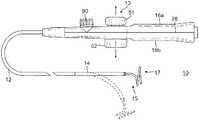
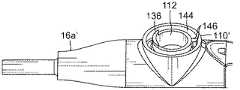
図1のカテーテルは、細長いカテーテル本体12、その細長いカテーテル本体12の遠位端にある偏向可能な中間部分14、及び先端部分15を含み、その先端部分は例えば、中間部分14の遠位端にある螺旋形状を有する遠位アセンブリ17を有する。カテーテルと共に使用するための制御ハンドル16は偏向ダイヤル50を有し、偏向ダイヤルは、制御ハンドル16から伸びてカテーテル本体12及び中間部分14を通る一組の牽引部材又はワイヤを作動させ、この中間部分の2方向偏向を行うように設定される。本発明の特徴に従い、この制御ハンドルには更に、遠位アセンブリ17の操作又は調節(例えば、遠位アセンブリの螺旋形状を収縮させる)において第3の牽引部材又はワイヤを制御するよう構成されたアクチュエータアセンブリが含まれる。 The catheter of FIG. 1 includes an
図2A及び2Bを参照すると、カテーテル本体12は、単一の、中央管腔又は軸管腔18を備える。カテーテル本体12は、可撓性、すなわち曲げることができるが、その長さに沿って実質的に非圧縮性である。カテーテル本体12は、いかなる好適な構造、かついかなる好適な材料からも作製されてよい。一実施形態では、カテーテル本体12は、ポリウレタン又はナイロン製の外壁22を含む。外壁22は、制御ハンドル16が回転されるとき、カテーテル10の先端部分が対応する方向に回転されるように、ステンレス鋼等の編みメッシュが埋め込まれて含んでおり、これによりカテーテル本体12のねじり剛性を増大させている。 With reference to FIGS. 2A and 2B, the
カテーテル本体12の外径は重要ではないが、好ましくは約8フレンチ以下である。同様に、外壁22の厚さは重要ではない。外壁22の内面は、任意の好適な材料、好ましくはポリイミドで作製できる補剛管20で裏打ちされる。補剛管20は、カテーテル本体12の近位端における外壁22関連する場所に保持される。第1の接着剤接合部23は、速乾性接着剤、例えば、Super Glue(登録商標)によって、補剛管20の遠位端と外壁22の遠位端との間に作製される。その後、第2の接着剤接合部25が、より遅乾性ではあるが、より強力な接着剤、例えばポリウレタンを使用して、補剛管20の近位端と外壁22の近位端との間に形成される。 The outer diameter of the
編組みされた外壁22を備えた補剛管20は、改善されたねじれ安定性を提供し、一方で、それと同時にカテーテルの壁厚を最小化し、それにより、単一管腔の直径を最大化する。補剛管20の外径は、外壁22の内径とほぼ同一、又はそれよりもわずかに小さい。ポリイミド管材は、非常に薄い壁である得るが、非常に優れた剛性を提供するため、好適である。これは、強度及び剛性を犠牲にせずに、管腔18の直径を最大限にする。ポリイミド材料は、屈曲したときに、ねじれる傾向があるため、通常は補剛管に使用されない。しかしながら、ポリウレタン、ナイロン、又は他の同様の材料、特にステンレス鋼編みメッシュを有する材料の外壁22と組み合わせて、ポリイミド補剛管20の屈曲したときのねじれる傾向は、カテーテルが使用される用途に対して本質的に解消されることが分かっている。 A stiffening
一実施形態では、外壁22は、約0.23cm(0.092インチ)の外径及び約0.16cm(0.063インチ)の内径を有し、ポリイミド補剛管20は、約0.156cm(0.0615インチ)の外径及び0.13cm(0.052インチ)の内径を有する。 In one embodiment, the
図2A、2B及び2Cに示されるように、中間部分14は、複数の管腔、例えば、第1管腔30、第2管腔31、第3管腔32、及び第4管腔33を有する管材19の、より短い部分を含む。管材19は、好ましくは、カテーテル本体12より柔軟である好適な非毒性材料で作製される。管材19に好適な材料は、ブレード入りポリウレタン(braided polyurethane)、すなわち、編みステンレス鋼などの埋込みメッシュを有するポリウレタンである。カテーテル本体12の外径と同様に、中間部分14の外径は、好ましくは、約8フレンチ以下である。管腔の大きさは、重要ではない。一実施形態では、この中間部分は、約0.23cm(7フレンチ、0.092インチ)の外径を有し、管腔は一般的に、約0.06cm(0.022インチ)の直径を有しほぼ同一の大きさであるか、又は、選択した管腔は、約0.09cm(0.036インチ)のわずかに大きな直径を有することが可能である。 As shown in FIGS. 2A, 2B, and 2C, the
カテーテル本体12を中間部分14に取り付ける手段が、図2A及び2Bに示されている。中間部分14の近位端は、ポリイミド補剛材20の外表面を受容する内部カウンターボア24を備える。中間部分14及びカテーテル本体12は、接着剤29等で取り付けられる。 Means for attaching the
図2A及び2Bに示すとおり、様々な構成要素、例えば、リードワイヤ及び複数の牽引ワイヤ、並びに任意の他のワイヤ又はケーブルは、カテーテル本体12の単一管腔18を通って延びる。カテーテル本体12に対する牽引ワイヤの長手方向動作によって、ユーザーが制御ハンドルを介してカテーテルの様々な部品を制御することが可能になる。一実施形態には、中間部分14を偏向させるための一対の偏向牽引ワイヤ42、及び先端部分15の遠位アセンブリ17を調節するための収縮牽引ワイヤ35がある。 As shown in FIGS. 2A and 2B, various components, such as a lead wire and a plurality of puller wires, and any other wires or cables extend through a
単一管腔カテーテル本体12は、単一管腔18本体が、カテーテル10を回転させるときにより良好な先端制御を可能にすることができるので、複数管腔本体よりも好ましいものであり得る。単一管腔18は、構成要素がそこを通って通過し、カテーテル本体内を自由に浮遊させることが可能になる。そのような構成要素が複数の管腔内で制限される場合、それらは、ハンドル16が回転されるときに、エネルギーを蓄積することができ、それによって、例えば、ハンドルが解放された場合に逆回転し、又は曲線周辺で湾曲した場合にひっくり返る傾向を有するカテーテル本体12が得られ、いずれも望ましくない性能特性である。 The single
1本の偏向牽引ワイヤ42は、カテーテル本体12の中央管腔18を通って、中間部分14の第2の管腔31内に延びる。もう1本の偏向牽引ワイヤ42が、中央管腔18を通って、中間部分14の第4管腔33内に延びる。この点において、管腔31、33は偏心しており、平面上で2方向偏向を行うために、互いに反対側の相対する位置にある。偏向牽引ワイヤ42の遠位端は、当業者には理解されるように、T字アンカー(図示なし)を用いることによって、中間部分14の遠位端近くの管材19の壁に固定される。中間部分14では、それぞれの偏向牽引ワイヤ42は、プラスチック(例えばTeflon(登録商標))のシース81を通って延び、これは、中間部分14が偏向させられるとき、偏向牽引ワイヤ42が中間部分14の管材19の壁に切り込むのを防止する。 A single
図2Bに示すように、偏向牽引ワイヤ42を包囲する関係にある圧縮コイル44は、カテーテル本体12の近位端から中間部分14の近位端へと延びる。圧縮コイル44は、任意の好適な金属、例えば、ステンレス鋼で作製される。圧縮コイル44は、それ自体にきつく巻きつけられ、圧縮に抵抗するのではなく、可撓性、すなわち、屈曲を提供する。圧縮コイル44の内径は、好ましくは、牽引ワイヤ42の直径よりもわずかに大きい。例えば、牽引ワイヤ42が約0.018cm(0.007インチ)の直径を有するとき、圧縮コイル44は、好ましくは、約0.020cm(0.008インチ)の内径を有する。牽引ワイヤ42を被覆するTeflon(登録商標)によって、それらが圧縮コイル44内を自由に摺動することが可能になる。圧縮コイル44の外表面は、可撓性の非導電シース27で被覆され、圧縮コイル44とリードワイヤ及びケーブル等の他の構成要素との間の接触を防止する。一実施形態では、非導電シースは、ポリイミド管材で作製される。 As shown in FIG. 2B, the
圧縮コイル44は、接着剤接合部50によって、カテーテル本体12内の補剛管20の近位端付近のそれらの近位端で固定され(図2B)、接着剤接合部49によって、第2の管腔31及び第4の管腔33内の中間部分14の近位端付近のその遠位端で固定される(図2B)。 The compression coils 44 are secured at their proximal ends near the proximal end of the stiffening
図1を参照し、中間部分14の遠位端は、マッピング及び/又はアブレーションのための遠位アセンブリ17である。図3及び3Aに示されているように、遠位アセンブリ17は、概ね直線状の近位領域38、及び概ね円形の主要領域39を含む。近位領域38は中間部分14に取り付けられ、概ね円形の主要領域は、マッピング及び/又はアブレーションのために複数の電極を保持する。図示されている実施形態において、この遠位アセンブリには管材61が含まれる。形状記憶部材54及び第3牽引部材又は収縮ワイヤ35は、非導電性保護管材55内を通って延びる。同様に保護管材は、遠位アセンブリに搭載されている電極のためのリードワイヤ40に沿って、管材61の管腔内を通って延びる。 Referring to FIG. 1, the distal end of the
この開示の実施形態において、収縮牽引ワイヤ35は概ね円形の主要領域39を収縮させるために提供され、例えば、心臓の円形領域又は管状領域をマッピング又はアブレーションする際に、それによってその直径を変化又は低減させる。収縮ワイヤ35は、以下に詳しく記載されるように、制御ハンドル16内に固定された近位端を有する。図2Aに示すように、収縮ワイヤ35は、カテーテル本体12の中央管腔18を通り、中間部分14の第3管腔32を通り、遠位アセンブリ17内へと伸びる。 In the embodiment of this disclosure, a
第3の圧縮コイル46は、カテーテル本体12、及び収縮ワイヤ35を包囲する関係で中間部分シャフト14内に位置する(図2A)。第3の圧縮コイル46は、カテーテル本体12の近位端から中間区域14の第3の管腔32の遠位端の近くまで延びる。第3の圧縮コイル46は、ステンレス鋼などの任意の好適な金属で作製され、可撓性(曲がる)を提供しながらも圧縮に耐えるように、それ自身に緊密に巻かれる。第3の圧縮コイル46の内径は、好ましくは、収縮ワイヤ35の直径よりもわずかに大きい。圧縮コイル46の外表面は、例えば、ポリイミド管材製の可撓性の非導電性シース68によって被覆される。第3の圧縮コイル46は、好ましくは、正方形又は矩形の断面積を有するワイヤで形成され、これにより、円形の断面積を有するワイヤから形成される圧縮コイルよりも圧縮性が小さくなる。その結果、第3の圧縮コイル46は、より多くの圧縮を吸収するため、収縮ワイヤ35が遠位アセンブリ17を収縮させるように操作されたときに、カテーテル本体12、特に、中間部分14を偏向させないようにする。 A
第3の圧縮コイル46は、その近位端が、近位の接着剤接合部50によって、カテーテル本体12の補剛管20に固定され、遠位の接着剤接合部73によって、中間区域14に固定される。 The
カテーテル10の接着剤接合部は、ポリウレタンの接着剤等を含んでよいことが理解される。接着剤は、管材壁内に作製された孔を通して、シリンジ等を使用して塗布されてよい。そのような穴は、針が永久的な孔を形成するに十分に加熱された管材壁を穿孔するもの、例えば、針等によって形成できる。次いで、接着剤は、管材内の部品周辺でウィッキングするように孔を通して導入され、構成要素の全周囲の周りに接着剤接合部を形成する。 It will be appreciated that the adhesive joint of the
遠位アセンブリ17の環電極に取り付けられたリードワイヤ40は、中間部分14の第1の管腔30(図2A)を通り、カテーテル本体12の中央管腔18を通り、制御ハンドル16を通って延び、環電極から受信した情報を受信及び表示するための適切なモニター又は他のデバイスに連結される連結装置(図示なし)内の近位端で終端する。カテーテル本体12の中央管腔18、制御ハンドル16及び中間部分14の近位端を通って伸びるリードワイヤ40の部分は、任意の好適な材料、好ましくはポリイミドで作製可能な保護シース62内に封入される。 A
電磁位置センサ(図示なし)は、遠位アセンブリ17の内部又は近くに取り付けられる。センサケーブル36は、センサから中間部分の管腔30内(電極リードワイヤ40に沿って)、カテーテル本体12の中央管腔18内、そして制御ハンドル内へと延び、センサケーブルは適切なコネクタ(図示なし)で終端する。 An electromagnetic position sensor (not shown) is mounted in or near the
図1を参照すると、制御ハンドル16は、好適な成形プロセスにより作られたプラスチック等の任意の好適な剛性材料で作製することが可能な、概ね細長いハンドルハウジングを備える。図示された実施形態では、ハウジングは、2つの対向する半分体16a及び16bを含み、これらは、概ね互いに鏡像関係にあり、接着剤、超音波接合又は他の適切な手段により、ハウジングの周囲の長手方向の周囲継ぎ目28に沿って接合される。 Referring to FIG. 1, the control handle 16 comprises a generally elongated handle housing that can be made of any suitable rigid material such as plastic made by a suitable molding process. In the illustrated embodiment, the housing includes two opposing
制御ハンドル16は、偏向制御アセンブリ13の構成要素を収納し、これには、第1及び第2牽引ワイヤ42を介して中間部分14の2方向偏向を行うための偏向ダイヤル50が含まれる。図4及び5A〜5Cに図示されるように、偏向ダイヤルを一方向に動かすことによって(矢印50で表わされる)、その方向の牽引ワイヤ42が近位側に引っ張られ、中間部分14をその方向に偏向させる。 Control handle 16 houses the components of
それぞれの牽引ワイヤ42は、ステンレス鋼又はニチノール等の任意の好適な金属で作製される。好ましくは、各牽引ワイヤはTeflon(登録商標)コーティングなどの低摩擦コーティングを有する。各牽引ワイヤは、好ましくは約0.015cm(0.006インチ)〜約0.030cm(0.012インチ)の範囲の直径を有する。好ましくは、両方の牽引ワイヤは同一の直径を有する。平坦な牽引ワイヤは丸い牽引ワイヤの代わりに用いてもよい。それらの断面の寸法は、丸い牽引ワイヤに相当する引張強度を与えることができるものである必要がある。あるいは、張力繊維(tensile fiber)を全体又は一部に使用することができる。張力繊維は、好ましくは、実質的に2480〜3200Mpa(412〜463ksi)の範囲の最大引張強度を有する、高分子密度ポリエチレン(例えば、Spectra(商標)又はDyneema(商標))、又は紡糸パラアラミド繊維ポリマー(例えば、Kevlar(商標))、又は溶融紡糸液晶ポリマー繊維ロープ(例えば、Vectran(商標))、又は高強度セラミック繊維(例えば、Nextel(商標))などの、高弾性率の繊維材料のものとすることができる。本明細書では、「繊維」(fiber)という用語は、張力繊維が織られた又は編まれた構造体であり得るという点で、複数形の繊維(fibers)と互換性を持って使用される。いかなる場合においても、これらの材料は可撓性である傾向を有し、カテーテル先端部を偏向させる場合においてより大きな到達距離のために滑車などとの巻き付き係合に使用されるときに、適切な耐久性を提供する。更に、それらは実質的に非伸張性であり、非伸張性であることが制御ハンドルの操作に対する応答性を増大させ、またMRIで概ね透明に見えるように非磁性である。材料が低密度であることは、その材料をX線機器に対してほぼ透明にする。材料は短絡を防止するために非電導性であることもできる。例えば、Vectran(商標)は、高い強度、高い耐摩耗性を有し、電気絶縁体、非磁性のポリマーであり、持続的な負荷状態の下での伸長性が低い。図4に図示されている実施形態において、各牽引部材42には、コネクタ81によって接続されている、遠位牽引ワイヤ部分42Dと近位張力繊維部分42Pとが含まれる。 Each
制御ハンドル16上の偏向ノブ50及び張力調節ノブ51を含む、偏向制御アセンブリ13の構成及びアセンブリを以下に説明する。アセンブリ13のロッカーアーム52は、制御ハンドル16の2つの半分体16A及び16Bの間に配置される。更に図6を参照し、ロッカーアーム52の環状突起54として形成されている半径方向軸受スリーブの頂部及び底部それぞれが、ハウジング半分体16A、16Bそれぞれの中に形成されているそれぞれの開口部56内に延びる。 The construction and assembly of the
偏向ノブ50及びロッカーアーム52は、それぞれの接合面55で相互連結機能によってそれぞれに回転連結される。偏向ノブ50に相対しているのは張力調節ノブ51であり、これは様々なメカニズム及び部品によってロッカーアーム52に連結され間接的に噛み合っている。ノブ51によって、操作者は、回転可能な偏向アーム75によって容易に調節することができる。図示されている張力調節ノブ51の実施形態は、張力調節アセンブリ70の一部であり、これにはノブ52に回転連結されているキャップ58、そのキャップ58に回転連結されている摩擦ねじ60、及びその摩擦ねじ60に噛み合っている摩擦ナット62も含まれている。ユーザーはノブ51を回して偏向ノブ50の回転運動の締まり又は張力を調節する。これは、アセンブリの構成要素に圧縮負荷を効果的に印加又は解除することによって、構成要素の接触表面間の摩擦トルクを増減させることによって行われる。好適な偏向アセンブリは、米国特許第7377906号に記述されており、この開示全体が、参照することにより本明細書に組み込まれる。 The
第3牽引ワイヤ(例えば収縮ワイヤ35)によって遠位アセンブリ17を操作するためには、制御ハンドル16内に収納されているスプールアセンブリ80によって作動させるために、その収縮ワイヤの近位端が、制御ハンドル16に固定されている。この開示の実施形態において、スプールアセンブリ80は、制御ハンドル内の偏向アセンブリ13の遠位側である。 In order to operate the
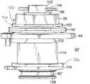
図7に例示されている実施形態において、スプールアセンブリ80には、テークアップスプール82(図8)、収縮ワイヤアンカーピン86(図8)、回り止めタブワッシャ84(図9)、及びユーザーインタフェースダイヤル90(図11A及び11B)が含まれる。図8にわかりやすく示されているように、スプール82は、内部に貫通する長手方向の穴94を備えた細長いシャフト本体92を有する。このシャフト本体92は、非円形、又は放射方向に非対称的な外形断面形状を有しているため、回転トルクを受け取り伝達することができる。本開示の実施形態において、断面形状はD字型であり、細長い平面的外側表面93を有している。シャフト本体92の一方の端には、内側リム98と外側リム100との間にテークアップドラム96が形成されており、ここで少なくとも内側リム98は、シャフト本体92よりも大きい直径を有する。シャフト本体の反対側の端102では、横断貫通穴104がその端102に形成されており、収縮ワイヤアンカーピン86(例えばヘッド106と2本の平行脚108を備えたコッターピン)を受けるようになっている。 In the embodiment illustrated in FIG. 7, the
スプールアセンブリ80は更に、ダイヤル90を自己保持性にするため、固定する及び/又は摩擦誘起するための複数のワッシャを含んでおり、その結果、ハンズフリー操作にユーザーが手を離した際に、ダイヤル90がその位置を保持する。 The
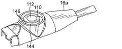
半径方向軸受スリーブ110(図10)は、制御ハンドルハウジング半分体16a内に形成され、貫通穴112を提供している。スプール82のシャフト本体92は、貫通穴112に収められ、これは内側リム98よりも小さいサイズになっているため、ドラムはハウジング半分体16aの内側に留まる。端102を備えたシャフト本体92の大部分はスリーブ110を貫通して、ハウジング半分体16aの外側へと延びている。参照を容易にする目的に限定して、本明細書においては、様々な構成要素の相対的な位置が、上記又は下記にそれぞれ記述されているが、制御ハンドル及びその内側構成要素は、任意の向きで組み立てられ使用できることが理解されよう。 A radial bearing sleeve 110 (FIG. 10) is formed in the control handle
スリーブ110のすぐ上のシャフト本体82に取り付けられているのは、円形中央穴132を備えたベースワッシャ130(図7)である。同様に、ベースワッシャはスプール82とは独立に回転可能(又は、緊密には回転連結されていない、これらは本明細書で互換可能な語として使用される)である。 Attached to the
ベースワッシャ130のすぐ上にあるのは、回り止めタブワッシャ84である。図9で分かりやすく示されているように、回り止めタブワッシャは、スプール82のシャフト本体92の外側横断面の寸法及び形状に対応した非円形の中央穴138を有しており、これによりスプールに対して回転連結している。回り止めタブワッシャの周縁エッジには、下記に詳しく述べるように、ダイヤル90と回転連結するための凹み構造又はノッチ140がある。また、周縁エッジには横方向(例えば下向き)に延びるタブ142がある。タブ142は、半径方向軸受スリーブ110を包囲する制御ハンドルハウジング半分体16aの外側表面に提供された凹んだチャネル144(図10)内に収まる。この円形チャネル144は2つの端又はストッパー146の間に、スリーブ周囲の所定の角度範囲で延びる。この端又はストッパーは、回り止めタブワッシャ84の回転移動距離量の範囲を制限し、これによりユーザーがダイヤル90を回転させる範囲を制限する。そのような制限がないと、例えば収縮ワイヤが破損限界点を超えて過剰に引っ張られた場合、損傷する可能性がある。開示の実施形態において、チャネル144はスリーブ110の周囲約350度に広がっている。 Immediately above the
回り止めタブワッシャ84のすぐ上にありシャフト本体92に取り付けられているのは、圧縮負荷に適応しているワッシャ148(図7)である。このワッシャは、ウェーブワッシャ、クローバーワッシャ、又は湾曲ディスクのベルヴィル型ばねワッシャであり得る。ワッシャ148は円形中央穴150を有しており、これによりスプール82に緊密には回転連結されないようになっている。 Just above the
更に、圧縮負荷ワッシャ148のすぐ上にありシャフト本体92に取り付けられているのは、円形中央穴154を備えたワッシャ152である。ワッシャ152は更に、スプール82とは独立に回転可能である。 Further, just above the
偏向牽引部材42と同様に、収縮ワイヤ35は、遠位ワイヤ部分35D及び張力繊維近位部分35Pを有し得る(図4)。張力繊維部分35Pは、ドラム96内に形成された横断穴158(図8)を通して挿入され、この穴はスプール82のシャフト本体92の中央長手方向貫通穴94に連通している。張力繊維部分35Pは、穴94の上方へ端102に向かって搬送され、アンカーピン86に到達し、穴104を通して挿入された脚108に固定されている。アンカーピン86は、アンカーピンの長手方向軸を中心に回転してゆるみを巻き取り、収縮ワイヤ35に好適な張力を印加する。次に脚108を引き離し、シャフト本体92の周りに反対方向に折り曲げ(矢印109)、ピン86を適所に固定する。 Similar to the
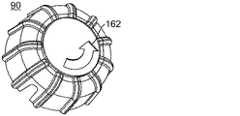
ロックワッシャ152のすぐ上にあるのはダイヤル90である。図11Aに示すように、ダイヤルは、ダイヤル90の外側上面に視覚的なしるし162を備えたキャップ本体を有し、このしるしは例えば、収縮ワイヤを引っ張るための回転方向を示す矢印である。ダイヤルの下側には、周縁壁163が、ダイヤルと回り止めタブワッシャとの間の回転連結のために、回り止めタブワッシャ84内に形成されたノッチ140に対応して噛み合うためのリブ164を備えて形成されている。同様に、ダイヤル90は回り止めタブワッシャ84を利用してスプール82に回転連結されている。ユーザーがダイヤル90を回すと、ダイヤルがスプール82を効果的に回転させ、スプールのドラム端96が、ドラム96上の収縮ワイヤの張力繊維部分35bを引っ張る。半径方向軸受スリーブ110のチャネル144内で動く回り止めタブワッシャ84のタブ142は、ダイヤル90の回転をガイドする。チャネル内のストッパー146は、ダイヤル90の回転を制限する。よって、ユーザーがダイヤルを使って作動させる収縮ワイヤ35の移動距離を、ストッパー146が効果的に制限し、その結果、ユーザーによる回転しすぎや破断を含む収縮ワイヤの破損が防止される。 Just above the
ダイヤル90は回り止めタブワッシャ94にスナップ嵌合される。図11Bに示すように、周縁リップ157が、ダイヤル90の周縁壁163の底部エッジ回りに形成される。リップ157は、ダイヤル90がシャフト本体92に押し付けられる際に、回り止めタブワッシャ94の周縁エッジを覆って回り、固定する。ダイヤル90の周縁壁に沿って均等間隔に形成された複数のスロット159によって、キャップ本体が弾性的に外側に拡大し、回り止めタブワッシャにスナップ嵌めされる。キャップ本体の下面に形成された半径方向の隆起部161は、シャフト本体92の上面167に接触する。 The
図12に例示されている別の実施形態において、スプールアセンブリ80’には、テークアップスプール82’(図13)、収縮ワイヤアンカーピン86、回り止めタブワッシャ84’(図16)、締結具88、及びユーザーインタフェースダイヤル90’(図18)が含まれる。スプール82’は、長手方向穴94を備えた細長いシャフト本体92’を有する(例えば図8を参照)。このシャフト本体92’は、非円形、又は半径方向に非対称的な断面形状を有しているため、回転トルクを受け取り伝達することができる。開示されている実施形態において、断面形状はD字型であり、これによりシャフト本体は細長い平面外側表面93を有する。シャフト本体92の一方の端には、内側リム98と外側リム100との間にテークアップドラム96が形成されており、ここで少なくとも内側リム98は、シャフト本体92よりも大きい直径を有する。シャフト本体92の反対側の端102’は、締結具88(例えば六角ジャムナット)を受容するためのねじが付いている。収縮ワイヤアンカーピン86(例えばコッターピン)(図8)を受容するよう、横断貫通穴104がねじ端102に形成されている。 In another embodiment illustrated in FIG. 12, the
スプールアセンブリ80’は更に、ダイヤル90’を自己保持性にするため、固定する及び/又は摩擦誘起するために複数の組み合わせワッシャを含んでおり、これによって、ハンズフリー操作中にユーザーが手を離してもダイヤル90’がその位置を保持する。 The spool assembly 80 'further includes a plurality of combination washers to make the dial 90' self-holding, fixed and / or friction-inducing so that the user can release hands during a hands-free operation. Even so, the dial 90 'maintains its position.
半径方向軸受スリーブ110’(図19)は、制御ハンドルハウジング半分体16a’内に形成され、貫通穴112を提供している。スプール82’のシャフト本体92’は、貫通穴112に収められ、貫通穴は内側リム98よりも小さいサイズになっている。シャフト本体92は套管114で覆われており(図12)、これによって、制御ハンドルが非ガラス繊維強化又は非炭素繊維強化の熱可塑性プラスチックで製造されている場合、長期的な圧縮負荷の間の塑性クリープを防止する。ねじ付き端102’を備えたシャフト本体92’の大部分は、スリーブ110’を貫通して、ハウジング半分体の外側へと延びている。 A
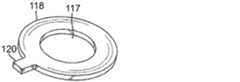
開示されている図12の実施形態において、ワッシャ118は内側リム98のすぐ上のスプール82のシャフト本体92に取り付けられ、制御ハンドルハウジング半分体の内部に収納される。ワッシャ118(図14)は円形中央穴117と、周縁エッジから延びるタブ120とを有し、このタブは、制御ハンドルハウジング半分体16aの内側表面内に形成された円形凹部124(図20)から延びる対応するスロット122に受容される。スロット122に受容されたタブ120によって、スプール82’及び制御ハンドルハウジング半分体16aに対するワッシャ118の回転がロックされる。 In the disclosed FIG. 12 embodiment, the
シャフト本体92上でタブ付きワッシャ118のすぐ上にあるのは、回転ワッシャ126(図15)である。これはシャフト本体92のサイズと、サイズ及び形状(例えばD字型)と対応する中央穴128を有し、その結果回転ワッシャはスプール82に回転連結される。回転ワッシャ126は更に、円形凹部124(図20)内の制御ハンドルハウジング半分体16aの内部に収まる。回転ワッシャ126と、回転しないタブ付きワッシャ118は、隣接面で互いに接触することにより、摩擦を生じる。圧縮下でアセンブリ80’を備えた制御ハンドルハウジング半分体16aに対してスプール82が回転される際に、この摩擦が、ダイヤル90を自己ロックするのに役立つ。 Immediately above the tabbed
シャフト本体92で回転ワッシャ126のすぐ上にあるのが、套管114(図12)である。これはスリーブ110の貫通穴112を外周の内側を覆うものである。套管は所定の長さを有し、これによりその外側端は、制御ハンドルハウジング半分体16aのスリーブ110’の外側表面と同一平面になって収まる。 Located directly above the
套管114のすぐ上にあるのが、円形中央穴132を備えたベースワッシャ130(図17)である。係合構造134(例えば直線エッジ部分)を備えた周縁エッジが提供され、これが、スリーブ110’の外側表面に形成された隆起部136(図19)に係合かつ接触し、これによって摩擦を生じる目的で、スプール82’及び制御ハンドルハウジング半分体16aに対するベースワッシャ130の回転をロックする。 Immediately above the
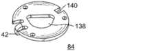
ベースワッシャ130のすぐ上にあるのは、回り止めタブ付きワッシャ84’である(図16)。回り止めタブワッシャは、スプール82のシャフト本体92の横断面の寸法及び形状に対応した非円形の中央穴138を有しており、これによりスプールに対して回転連結している。回り止めタブワッシャの周縁には、複数の凹部構造又はノッチ140がある。例示されている実施形態においては、ダイヤル90’と回転連結するため、周縁エッジに沿って配置された4つのノッチ140がある。また、周縁エッジには横方向(例えば下向き)に延びるタブ142がある。タブ142は、半径方向軸受スリーブ110を包囲する制御ハンドルハウジング半分体16a’の外側表面に提供された凹んだチャネル144内に収まる。この円形チャネル144は2つの端又はストッパー146の間に、スリーブ周囲の所定の角度範囲で延びる。この端又はストッパーは、回り止めタブワッシャ84の回転移動距離量の範囲を制限し、これによりユーザーがダイヤル90を回転できる範囲が制限される。そのような制限がないと、例えば破損限界点を超えて過剰に引っ張られた場合、収縮ワイヤが損傷する可能性がある。開示の実施形態において、図19のチャネル144も、スリーブ110の回りで約350度に延びている。 Immediately above the
シャフト本体92’上で回り止めタブワッシャ84’のすぐ上に取り付けられているのは、圧縮負荷に適応している一対のワッシャ148(例えばスロット付きベルヴィルワッシャ)である。このワッシャは円形中央穴を有しているため、スプール82のシャフト本体92から独立に回転可能である。 Mounted just above the detent tab washer 84 'on the shaft body 92' are a pair of washers 148 (e.g., slotted Belleville washers) adapted to compressive loads. Since this washer has a circular central hole, it can rotate independently of the
更に、一対の圧縮ワッシャ148のすぐ上でシャフト本体92に取り付けられているのは、円形中央穴154を備えたワッシャ152である。ワッシャ152は更に、スプール82とは独立に回転可能である。 Further, attached to the
ワッシャ152のすぐ上にあるのは締結具88(例えば六角ジャムナット)であり、これはシャフト本体92のねじ付き端102にねじで固定される。締結具88はシャフト本体92上に締結され、一対のワッシャ148に対して圧縮負荷を生成し、これによってアセンブリ80のワッシャの様々な接触表面に摩擦をもたらす。ワッシャ152のエッジ部分156は、六角ジャムナットのエッジに沿って回され(矢印180)、ナットを定位置に固定し、緩むのを防ぐ。ナットを定位置に固定する別の方法は、例えばLOCTITE 272永久ねじロック接着剤などのはめ合い用化合物(retaining compound)を使用することである。 Immediately above the
収縮ワイヤ35の張力繊維部分35Pは、ドラム96内に形成された横断穴158を通して挿入され、この穴はスプール82’のシャフト本体92’の中央長手方向貫通穴94に連通している。張力繊維部分35Pは、穴の上方へ端102に向かって搬送され、アンカーピン86に達し、上述と同様にして固定される。 The
アンカーピン86の上にあるのはダイヤル90’である。開示されている実施形態において、キャップ本体は回り止めタブワッシャ94’に超音波溶接又は接着剤接着されている。図18に示すように、ダイヤルと回り止めタブワッシャとの間の回転連結のために回り止めタブワッシャ84に形成されたノッチ140に対応して嵌合するための複数のリブ164を備えた、周縁壁163が形成されている。大きな/幅広のリブ164は、サイズと形状がより大きく/より幅広のノッチ140に対応している。小さな/幅狭のリブ164’のサイズと形状は、より小さく/より幅狭のノッチ140’のサイズと形状に対応しており、これらは互いに超音波溶接又は接着剤接着されている。同様に、ダイヤル90は回り止めタブワッシャ84を利用してスプール82に回転連結されている。ユーザーがダイヤル90を回すと、ダイヤルがスプール82を回転させ、そのドラム端96が、ドラム96上の収縮ワイヤの張力繊維部分35bを引っ張る。上述のように、タブ142が移動するチャネル144内に形成されたストッパー146が、ダイヤル90の回転を制限する。よって、ユーザーがダイヤルを使って作動させる収縮ワイヤ35の移動距離を、ストッパー146が効果的に制限し、その結果、ユーザーによる回転しすぎや破断を含む収縮ワイヤの破損が防止される。 Above the
アセンブリに自己保持性をもたらす望ましい量の摩擦トルクを発生させるため、複数の組み合わせの回転及び非回転ワッシャ、ワッシャのサイズ(又は接触表面積)、及びスプール上のワッシャの相対的位置(又は「積層順序」)を含め、アセンブリ80及び80’内の様々な要素及びパラメータを変化させることが可能であることが理解されよう。加えて、これらの要素及びパラメータは、特にユーザーインタフェースダイヤルなど、アセンブリの高さ又は「プロファイル」にも影響するため、本発明は開示されている実施形態に制限されるものではない。また、上述のどの要素及びパラメータも、自己ロックダイヤルを提供するために発生させた均一な静的摩擦及び/又は動的摩擦のトルクの量に影響し得ることが理解されよう。更に、制御ハンドル内の空間的拘束、及び制御ハンドル外側の形状に関する懸念について、検討が行われる。単一のワッシャ積層体の圧縮を強くすることにより、ワッシャ間の接触圧力が増大するにつれて静摩擦係数及び動摩擦係数は大きく分散し、これによって、「ガクガクと(jerky feeling)」変化する制御ダイヤルがもたらされる。この点において、ワッシャ間の静摩擦係数と動摩擦係数は、スムーズなダイヤル操作のために、互いに類似でなければならない。また、保持トルクは、軸圧縮力、摩擦係数、及びワッシャの内径と外径によって決まることも理解されよう。よって、様々な組合せのワッシャを使用することができる。 Multiple combinations of rotating and non-rotating washers, washer size (or contact surface area), and relative position of the washers on the spool (or “stacking order” to generate the desired amount of friction torque that provides self-holding to the assembly It will be appreciated that various elements and parameters within the
使用あたって、望ましいマッピング位置に位置付けられた遠位端を有する、好適なガイディングシース(guiding sheath)が、患者に挿入される。本発明に関連して使用するための好適なガイディングシースの例は、Biosense Webster,Inc.(Diamond Bar,Calif.)から市販されているPreface(商標)ブレイディング・ガイディング・シースが挙げられる。シースの遠位端は、心室のうちの1つ、例えば、心房内に誘導される。本発明に従うカテーテルは、その遠位端がガイディングシースの遠位端から延在するまで、ガイディングシースから提供される。カテーテルがガイディングシースを通して供給される際、遠位アセンブリ17は、伸張され、シースをかろうじて通り抜ける。カテーテルの遠位端が望ましい位置に位置付けられると、ガイディングシースは、近位に引っ張られ、偏向可能な中間部分14及び遠位アセンブリ17が、シースの外側に延びることが可能になり、遠位アセンブリ17は、形状記憶により、その本来の形状に戻る。 In use, a suitable guiding sheath having a distal end positioned at the desired mapping location is inserted into the patient. Examples of suitable guiding sheaths for use in connection with the present invention can be found in Biosense Webster, Inc. Preface ™ braiding guiding sheath commercially available from (Diamond Bar, Calif.). The distal end of the sheath is guided into one of the ventricles, eg, the atrium. A catheter according to the present invention is provided from the guiding sheath until its distal end extends from the distal end of the guiding sheath. As the catheter is delivered through the guiding sheath, the
次に、中間部分14を偏向させるために偏向ダイヤル50を操作及び回転させることにより、遠位アセンブリ17は、アセンブリ17のほぼ円形の主領域39の外周が管状領域の内周に接触するように、肺静脈又は他の管状領域(上大静脈又は下大静脈など)の中に挿入される。偏向ダイヤル50を一方向に回すことにより、中間部分14がその方向に偏向する。偏向50を反対方向に回すことにより、中間部分14がその反対方向に偏向する。偏向ダイヤル50の張力は、張力ダイヤル51を操作及び回転させることによって調節される。ダイヤル51の一方向への回転は、張力を増加させる。ダイヤル51の反対方向への回転は、張力を減少させる。 Next, by manipulating and rotating the
ほぼ円形の部分39にある電極の円形配列は、電極間の異所性拍動を特定することが可能なように、管状構造の周縁での電気活性の測定を可能にする。ほぼ円形の主領域39の寸法は、肺静脈又は心臓若しくは心臓近傍の他の管状構造の直径に沿った電気活性の測定を可能にするが、それは円形主領域が肺静脈又は他の管状構造のものにほぼ相当する直径を有するからである。ダイヤル90を操作することにより、アセンブリ17、特にほぼ円形の主領域39は、肺静脈又は他の環状構造に嵌合するように調節される。開示されている実施形態において、ダイヤルを一方向に回転させることにより、収縮ワイヤ35が近位側に引っ張られ、ほぼ円形の領域39を引き締め、直径を減少させる。ダイヤルを反対方向に回転させることにより、収縮ワイヤ35は解放され、前の直径に戻る。ほぼ円形である主領域の円周の、好ましくは少なくとも約50%、より好ましくは少なくとも約70%、更により好ましくは少なくとも約80%が、管状領域の内側の円周に接触する。 The circular arrangement of electrodes in the generally
上記の説明文は、現時点における本発明の好ましい実施形態に基づいて示したものである。当業者であれば、本発明の原理、趣旨及び範囲を大きく逸脱することなく、本願に述べた構造の改変及び変更を実施することが可能であることは認識されるところであろう。例えば、カテーテルは、第3の牽引ワイヤがガイドワイヤ又は針などの別の構成要素を前進及び後退させるように、適応させることができる。当業者によれば理解されるように、図面は必ずしも一定の縮尺ではない。したがって、上記の説明文は、本願に述べられ、以下の添付図面に示される厳密な構造のみに関係したものとして読み取るべきではなく、むしろ、以下の最も完全で公正な範囲を有するとされる特許請求の範囲と一致し、かつそれらを補助するものとして読み取るべきである。 The above description is based on the presently preferred embodiments of the invention. Those skilled in the art will recognize that modifications and variations of the structure described herein can be made without departing significantly from the principles, spirit and scope of the invention. For example, the catheter can be adapted such that a third puller wire advances and retracts another component such as a guidewire or needle. As will be appreciated by those skilled in the art, the drawings are not necessarily to scale. Accordingly, the above description should not be read as referring only to the precise structure described in the present application and illustrated in the accompanying drawings below, but rather to the patent having the following most complete and fair scope: It should be read as being consistent with and assisting with the claims.
〔実施の態様〕
(1) 細長い本体、該細長い本体の遠位にある遠位アセンブリを有する医療機器のための制御ハンドルであって、該遠位アセンブリは調節可能な構成を有し、該医療機器は更に該細長い本体及び該遠位アセンブリを通って延在する牽引部材を含み、該制御ハンドルが、
チャネルを備えて形成された外側表面を有するハウジングと、
アクチュエータアセンブリと、を含み、該アクチュエータアセンブリが、
ユーザーインタフェース回転ダイヤルと、
該ハウジングの貫通穴を通って挿入されるシャフト本体を有し、該牽引部材が巻き付けられるドラムを有しているスプールと、
該シャフト本体に取り付けられた回り止めワッシャであって、該ダイヤルから該シャフト本体へ回転運動を伝達するために該第1ワッシャが該ダイヤルに回転連結されており、該ワッシャが該回り止めワッシャの動きをガイドするよう該チャネル内を動くタブを有する、回り止めワッシャと、
該シャフト本体に取り付けられた少なくとも1つの摩擦誘起性ワッシャと、
該摩擦誘起性ワッシャに対して圧縮負荷を発生させるよう構成され、該シャフト本体に取り付けられた締結具と、を含む、制御ハンドル。
(2) 前記ドラムが前記制御ハンドルハウジングの内部にある、実施態様1に記載の制御ハンドル。
(3) 前記ワッシャが前記制御ハンドルハウジングの外部にある、実施態様1に記載の制御ハンドル。
(4) 前記少なくとも1つの摩擦誘起性ワッシャが前記制御ハンドルハウジングの外部にある、実施態様1に記載の制御ハンドル。
(5) 前記アクチュエータアセンブリが更に、前記制御ハンドルハウジングの内側の前記シャフト本体に取り付けられた第2ワッシャを含み、該第2ワッシャが前記ドラムのリムと摩擦誘起的に接触しており、該第2ワッシャが該リムに対して回転しないようロックされている、実施態様1に記載の制御ハンドル。
(6) 前記チャネルが、前記制御ハンドルハウジング内の前記貫通穴をほぼ包囲する円形形状を有する、実施態様1に記載の制御ハンドル。
(7) 前記チャネルが、前記タブの該チャネル内での動きを制限するためのストッパーを有する、実施態様1に記載の制御ハンドル。
(8) 前記アクチュエータアセンブリが更に、前記回り止めワッシャに摩擦誘起的に接触して前記シャフト本体に取り付けられている別のワッシャを含み、該第2ワッシャが該シャフト本体に対して回転しないようロックされている、実施態様1に記載の制御ハンドル。
(9) 前記締結具が、前記シャフト本体上に螺着されたナットである、実施態様1に記載の制御ハンドル。
(10) 前記アクチュエータアセンブリが更にアンカーを含み、前記牽引部材の近位端が該アンカーに取り付けられている、実施態様1に記載の制御ハンドル。Embodiment
(1) A control handle for a medical device having an elongate body, a distal assembly distal to the elongate body, the distal assembly having an adjustable configuration, the medical device further comprising the elongate body A traction member extending through the body and the distal assembly, the control handle comprising:
A housing having an outer surface formed with a channel;
An actuator assembly, the actuator assembly comprising:
A user interface rotary dial,
A spool having a shaft body inserted through a through hole in the housing and having a drum around which the traction member is wound;
A detent washer attached to the shaft body, wherein the first washer is rotationally coupled to the dial to transmit rotational motion from the dial to the shaft body, and the washer is connected to the detent washer. A detent washer having a tab that moves within the channel to guide movement;
At least one friction-inducing washer attached to the shaft body;
A control handle configured to generate a compressive load on the friction-inducing washer and attached to the shaft body.
(2) The control handle of embodiment 1, wherein the drum is inside the control handle housing.
(3) The control handle of embodiment 1, wherein the washer is external to the control handle housing.
4. The control handle of embodiment 1, wherein the at least one friction-inducing washer is external to the control handle housing.
(5) The actuator assembly further includes a second washer attached to the shaft body inside the control handle housing, wherein the second washer is frictionally in contact with the rim of the drum, 2. The control handle of embodiment 1, wherein the two washers are locked against rotation with respect to the rim.
6. The control handle of embodiment 1, wherein the channel has a circular shape that substantially surrounds the through hole in the control handle housing.
7. The control handle of embodiment 1, wherein the channel has a stopper for restricting movement of the tab within the channel.
(8) The actuator assembly further includes another washer frictionally in contact with the detent washer and attached to the shaft body, the second washer being locked against rotation with respect to the shaft body. 2. The control handle of embodiment 1, wherein:
(9) The control handle according to embodiment 1, wherein the fastener is a nut screwed onto the shaft body.
10. The control handle of embodiment 1, wherein the actuator assembly further includes an anchor, and the proximal end of the traction member is attached to the anchor.
(11) 細長い本体と、
調節可能な構成を有する遠位アセンブリと、
該細長い本体と該遠位アセンブリとを通って延びる牽引部材と、
制御ハンドルと、を含むカテーテルであって、該制御ハンドルが、
チャネルを備えて形成された外側表面を有するハウジングと、
アクチュエータアセンブリとを含み、該アクチュエータアセンブリが、
ユーザーインタフェース回転ダイヤルと、
該ハウジングの貫通穴を通って挿入されるシャフト本体を有し、該牽引部材が巻き付けられるドラムを有しているスプールと、
該シャフト本体に取り付けられた回り止めワッシャであって、該ダイヤルから該シャフト本体へ回転運動を伝達するように該第1ワッシャが該ダイヤルに回転連結されており、該ワッシャが該回り止めワッシャの動きをガイドするよう該チャネル内を動くタブを有する、回り止めワッシャと、
該シャフト本体に取り付けられた少なくとも1つの摩擦誘起性ワッシャと、
該摩擦誘起性ワッシャに対して圧縮負荷を発生させるよう構成された、該シャフト本体に取り付けられた締結具と、を含む、カテーテル。
(12) 前記制御ハンドルから前記細長い本体の遠位端まで又はその近くまで延びる一対の牽引部材を更に含み、該制御ハンドルが、前記一対の牽引部材に作用するよう構成された偏向アセンブリを更に含む、実施態様11に記載のカテーテル。
(13) 前記遠位アセンブリが概ね円形の遠位部分及び概ね直線の近位部分を有し、前記牽引部材の調節によって、その概ね円形の遠位部分を変化させる、実施態様11に記載のカテーテル。
(14) 前記アクチュエータアセンブリが更に、前記制御ハンドルハウジングの内側の前記シャフト本体に取り付けられた第2ワッシャを含み、該第2ワッシャが前記ドラムのリムに摩擦誘起的に接触しており、該第2ワッシャが該リムに対して回転しないようロックされている、実施態様11に記載の制御ハンドル。
(15) 前記チャネルが、前記制御ハンドルハウジング内の前記貫通穴をほぼ包囲している円形形状を有する、実施態様11に記載の制御ハンドル。
(16) 前記チャネルが、前記タブの該チャネル内での動きを制限するためのストッパーを有する、実施態様11に記載の制御ハンドル。
(17) 前記アクチュエータアセンブリが更に、前記回り止めワッシャに摩擦誘起的に接触して前記シャフト本体に取り付けられている別のワッシャを含み、該第2ワッシャが該シャフト本体に対して回転しないようロックされている、実施態様11に記載の制御ハンドル。
(18) 前記締結具が、前記シャフト本体上に螺着されたナットである、実施態様11に記載の制御ハンドル。
(19) 前記アクチュエータアセンブリが更にアンカーを含み、前記牽引部材の近位が該アンカーに取り付けられている、実施態様11に記載の制御ハンドル。
(20) 前記アクチュエータアセンブリが更に、前記制御ハンドルハウジング内の前記貫通穴の内側を覆う套管を含む、実施態様11に記載の制御ハンドル。(11) an elongated body;
A distal assembly having an adjustable configuration;
A traction member extending through the elongate body and the distal assembly;
A control handle, the control handle comprising:
A housing having an outer surface formed with a channel;
An actuator assembly, the actuator assembly comprising:
A user interface rotary dial,
A spool having a shaft body inserted through a through hole in the housing and having a drum around which the traction member is wound;
A non-rotating washer attached to the shaft body, wherein the first washer is rotationally coupled to the dial so as to transmit rotational motion from the dial to the shaft body, and the washer is connected to the anti-rotation washer A detent washer having a tab that moves within the channel to guide movement;
At least one friction-inducing washer attached to the shaft body;
A fastener attached to the shaft body configured to generate a compressive load on the friction-inducing washer.
(12) A pair of traction members extending from the control handle to or near the distal end of the elongate body, the control handle further including a deflection assembly configured to act on the pair of traction members.
The catheter of claim 11, wherein the distal assembly has a generally circular distal portion and a generally straight proximal portion, the adjustment of the traction member changing the generally circular distal portion. .
(14) The actuator assembly further includes a second washer attached to the shaft body inside the control handle housing, the second washer frictionally in contact with the rim of the drum, 12. The control handle of embodiment 11, wherein the two washers are locked against rotation with respect to the rim.
15. The control handle of embodiment 11, wherein the channel has a circular shape that substantially surrounds the through hole in the control handle housing.
16. The control handle of embodiment 11 wherein the channel has a stopper to limit movement of the tab within the channel.
(17) The actuator assembly further includes another washer attached to the shaft body in friction-inducing contact with the detent washer, the second washer locked against rotation with respect to the shaft body.
(18) The control handle according to embodiment 11, wherein the fastener is a nut screwed onto the shaft body.
19. The control handle of embodiment 11, wherein the actuator assembly further includes an anchor, and the proximal of the traction member is attached to the anchor.
20. The control handle of embodiment 11, wherein the actuator assembly further includes a cannula that covers the inside of the through hole in the control handle housing.
Claims (20)
Translated fromJapaneseチャネルを備えて形成された外側表面を有するハウジングと、
アクチュエータアセンブリと、を含み、該アクチュエータアセンブリが、
ユーザーインタフェース回転ダイヤルと、
該ハウジングの貫通穴を通って挿入されるシャフト本体を有し、該牽引部材が巻き付けられるドラムを有しているスプールと、
該シャフト本体に取り付けられた回り止めワッシャであって、該ダイヤルから該シャフト本体へ回転運動を伝達するために該第1ワッシャが該ダイヤルに回転連結されており、該ワッシャが該回り止めワッシャの動きをガイドするよう該チャネル内を動くタブを有する、回り止めワッシャと、
該シャフト本体に取り付けられた少なくとも1つの摩擦誘起性ワッシャと、
該摩擦誘起性ワッシャに対して圧縮負荷を発生させるよう構成され、該シャフト本体に取り付けられた締結具と、を含む、制御ハンドル。A control handle for a medical device having an elongate body, a distal assembly distal to the elongate body, the distal assembly having an adjustable configuration, the medical device further comprising the elongate body and the A traction member extending through the distal assembly, the control handle comprising:
A housing having an outer surface formed with a channel;
An actuator assembly, the actuator assembly comprising:
A user interface rotary dial,
A spool having a shaft body inserted through a through hole in the housing and having a drum around which the traction member is wound;
A detent washer attached to the shaft body, wherein the first washer is rotationally coupled to the dial to transmit rotational motion from the dial to the shaft body, and the washer is connected to the detent washer. A detent washer having a tab that moves within the channel to guide movement;
At least one friction-inducing washer attached to the shaft body;
A control handle configured to generate a compressive load on the friction-inducing washer and attached to the shaft body.
調節可能な構成を有する遠位アセンブリと、
該細長い本体と該遠位アセンブリとを通って延びる牽引部材と、
制御ハンドルと、を含むカテーテルであって、該制御ハンドルが、
チャネルを備えて形成された外側表面を有するハウジングと、
アクチュエータアセンブリとを含み、該アクチュエータアセンブリが、
ユーザーインタフェース回転ダイヤルと、
該ハウジングの貫通穴を通って挿入されるシャフト本体を有し、該牽引部材が巻き付けられるドラムを有しているスプールと、
該シャフト本体に取り付けられた回り止めワッシャであって、該ダイヤルから該シャフト本体へ回転運動を伝達するように該第1ワッシャが該ダイヤルに回転連結されており、該ワッシャが該回り止めワッシャの動きをガイドするよう該チャネル内を動くタブを有する、回り止めワッシャと、
該シャフト本体に取り付けられた少なくとも1つの摩擦誘起性ワッシャと、
該摩擦誘起性ワッシャに対して圧縮負荷を発生させるよう構成された、該シャフト本体に取り付けられた締結具と、を含む、カテーテル。An elongated body;
A distal assembly having an adjustable configuration;
A traction member extending through the elongate body and the distal assembly;
A control handle, the control handle comprising:
A housing having an outer surface formed with a channel;
An actuator assembly, the actuator assembly comprising:
A user interface rotary dial,
A spool having a shaft body inserted through a through hole in the housing and having a drum around which the traction member is wound;
A non-rotating washer attached to the shaft body, wherein the first washer is rotationally coupled to the dial so as to transmit rotational movement from the dial to the shaft body, and the washer is connected to the anti-rotation washer. A detent washer having a tab that moves within the channel to guide movement;
At least one friction-inducing washer attached to the shaft body;
A fastener attached to the shaft body configured to generate a compressive load on the friction-inducing washer.
Applications Claiming Priority (2)
| Application Number | Priority Date | Filing Date | Title |
|---|---|---|---|
| US13/300,411 | 2011-11-18 | ||
| US13/300,411US9199061B2 (en) | 2011-11-18 | 2011-11-18 | Medical device control handle |
Publications (2)
| Publication Number | Publication Date |
|---|---|
| JP2013106952Atrue JP2013106952A (en) | 2013-06-06 |
| JP6033648B2 JP6033648B2 (en) | 2016-11-30 |
Family
ID=47227624
Family Applications (1)
| Application Number | Title | Priority Date | Filing Date |
|---|---|---|---|
| JP2012251984AActiveJP6033648B2 (en) | 2011-11-18 | 2012-11-16 | Medical equipment control handle |
Country Status (8)
| Country | Link |
|---|---|
| US (2) | US9199061B2 (en) |
| EP (1) | EP2594307B1 (en) |
| JP (1) | JP6033648B2 (en) |
| CN (1) | CN103120825B (en) |
| AU (1) | AU2012250288B2 (en) |
| CA (1) | CA2795751A1 (en) |
| IL (1) | IL222985A (en) |
| RU (1) | RU2617271C2 (en) |
Families Citing this family (42)
| Publication number | Priority date | Publication date | Assignee | Title |
|---|---|---|---|---|
| US8968355B2 (en)* | 2008-08-04 | 2015-03-03 | Covidien Lp | Articulating surgical device |
| US8556850B2 (en) | 2008-12-31 | 2013-10-15 | St. Jude Medical, Atrial Fibrillation Division, Inc. | Shaft and handle for a catheter with independently-deflectable segments |
| US8676290B2 (en)* | 2010-05-11 | 2014-03-18 | St. Jude Medical, Atrial Fibrillation Division, Inc. | Multi-directional catheter control handle |
| WO2012106185A1 (en)* | 2011-01-31 | 2012-08-09 | Boston Scientific Scimed, Inc. | Articulation section with locking |
| US20130012958A1 (en)* | 2011-07-08 | 2013-01-10 | Stanislaw Marczyk | Surgical Device with Articulation and Wrist Rotation |
| US9949623B2 (en)* | 2013-05-17 | 2018-04-24 | Endochoice, Inc. | Endoscope control unit with braking system |
| CN104083214B (en)* | 2014-06-13 | 2017-01-25 | 先健科技(深圳)有限公司 | Bend-adjustable medical catheter and assembling method thereof |
| US10238845B2 (en) | 2014-09-19 | 2019-03-26 | Acclarent, Inc. | Balloon catheter assembly |
| US9878131B2 (en)* | 2014-12-10 | 2018-01-30 | Biosense Webster (Israel) Ltd. | Guide wire restraint device |
| CN105012519A (en)* | 2015-07-02 | 2015-11-04 | 广西壮族自治区药用植物园 | Health-preserving wine capable of strengthening knee and tonifying kidney |
| US10695089B2 (en)* | 2015-07-10 | 2020-06-30 | Medtronic, Inc. | Medical tools and methods for gaining access to extravascular spaces |
| US10456161B2 (en)* | 2016-04-14 | 2019-10-29 | Covidien Lp | Tissue-removing catheter with adjustment mechanism |
| US9962180B2 (en)* | 2016-04-27 | 2018-05-08 | Covidien Lp | Catheter including drive assembly for rotating and reciprocating tissue-removing element |
| US10588495B2 (en) | 2016-07-28 | 2020-03-17 | Cook Medical Technologies LL | Brake mechanism of a steerable catheter |
| US11701159B2 (en)* | 2016-09-02 | 2023-07-18 | Medtronic Cryocath Lp | MRI-compatible cryocatheters and system |
| US10603472B2 (en)* | 2016-10-25 | 2020-03-31 | Biosense Webster (Israel) Ltd. | Guidewires having improved mechanical strength and electromagnetic shielding |
| US10682496B2 (en)* | 2017-11-16 | 2020-06-16 | Biosense Webster (Israel) Ltd. | Catheter handle |
| AU2018370841A1 (en)* | 2017-11-21 | 2020-05-21 | Boston Scientific Scimed, Inc. | Medical devices and related methods |
| KR102732789B1 (en)* | 2018-01-08 | 2024-11-22 | 지아이 사이언티픽, 엘엘씨 | Device delivery tools and systems |
| US11364365B2 (en)* | 2019-05-18 | 2022-06-21 | Cairdac | Delivery system with an operating handle controlling a steerable catheter for the implantation of a leadless cardiac capsule |
| US11794389B2 (en) | 2019-09-06 | 2023-10-24 | Ambu A/S | Tip part assembly for an endoscope |
| US11969280B2 (en) | 2020-01-07 | 2024-04-30 | Cleerly, Inc. | Systems, methods, and devices for medical image analysis, diagnosis, risk stratification, decision making and/or disease tracking |
| US20220392065A1 (en) | 2020-01-07 | 2022-12-08 | Cleerly, Inc. | Systems, methods, and devices for medical image analysis, diagnosis, risk stratification, decision making and/or disease tracking |
| US11501436B2 (en) | 2020-01-07 | 2022-11-15 | Cleerly, Inc. | Systems, methods, and devices for medical image analysis, diagnosis, risk stratification, decision making and/or disease tracking |
| US12402782B2 (en) | 2020-04-30 | 2025-09-02 | Ambu A/S | Endoscope control system |
| EP3903660A1 (en)* | 2020-04-30 | 2021-11-03 | Ambu A/S | A method of assembly of an endoscope control system |
| US11964114B2 (en)* | 2020-05-22 | 2024-04-23 | Acclarent, Inc. | Shaft deflection control assembly for ENT guide instrument |
| EP4167892A4 (en) | 2020-06-19 | 2024-10-30 | Remedy Robotics, Inc. | SYSTEMS AND METHODS FOR GUIDING INTRALUMINAL DEVICES WITHIN THE VASCULAR SYSTEM |
| CN112057135B (en)* | 2020-08-31 | 2022-11-01 | 武汉佑康科技有限公司 | Electronic mirror catheter structure with stepless self-locking handle |
| CN112294430B (en)* | 2020-09-17 | 2022-05-13 | 杭州堃博生物科技有限公司 | Radio frequency ablation catheter and preparation method thereof |
| CN112402008B (en)* | 2020-09-17 | 2022-07-12 | 杭州堃博生物科技有限公司 | Radio frequency ablation catheter and system thereof |
| JP6967644B1 (en)* | 2020-10-22 | 2021-11-17 | 東郷メディキット株式会社 | Medical equipment |
| EP4364163A1 (en) | 2021-07-01 | 2024-05-08 | Remedy Robotics, Inc. | Vision-based position and orientation determination for endovascular tools |
| US11707332B2 (en) | 2021-07-01 | 2023-07-25 | Remedy Robotics, Inc. | Image space control for endovascular tools |
| US12121307B2 (en) | 2021-07-01 | 2024-10-22 | Remedy Robotics, Inc. | Vision-based position and orientation determination for endovascular tools |
| CN113616318B (en)* | 2021-09-06 | 2022-05-20 | 上海康德莱医疗器械股份有限公司 | Renal sympathetic nerve ablation system and method |
| US12318161B2 (en) | 2021-10-05 | 2025-06-03 | Siemens Healthineers Endovascular Robotics, Inc. | Robotic actuation of elongated medical devices |
| CN217365782U (en)* | 2021-12-24 | 2022-09-06 | 浙江优亿医疗器械股份有限公司 | Disposable soft mirror |
| CN114404116B (en)* | 2022-01-25 | 2025-07-25 | 北京领健医疗科技有限公司 | Sheath tube bending adjusting handle, conveying device and valve repair system |
| US12406365B2 (en) | 2022-03-10 | 2025-09-02 | Cleerly, Inc. | Systems, devices, and methods for non-invasive image-based plaque analysis and risk determination |
| US20250217981A1 (en) | 2022-03-10 | 2025-07-03 | Cleerly, Inc. | Systems, methods, and devices for image-based plaque analysis and risk determination |
| US20250143657A1 (en) | 2022-03-10 | 2025-05-08 | Cleerly, Inc. | Systems, devices, and methods for non-invasive image-based plaque analysis and risk determination |
Citations (9)
| Publication number | Priority date | Publication date | Assignee | Title |
|---|---|---|---|---|
| US5363861A (en)* | 1991-11-08 | 1994-11-15 | Ep Technologies, Inc. | Electrode tip assembly with variable resistance to bending |
| US5462527A (en)* | 1993-06-29 | 1995-10-31 | C.R. Bard, Inc. | Actuator for use with steerable catheter |
| US5667476A (en)* | 1995-06-05 | 1997-09-16 | Vision-Sciences, Inc. | Endoscope articulation system to reduce effort during articulation of an endoscope |
| US6126633A (en)* | 1997-07-11 | 2000-10-03 | Olympus Optical Co., Ltd. | Surgical instrument |
| US6533783B1 (en)* | 1999-07-14 | 2003-03-18 | Biotronik Mess -Und Therapiegeraete Gmbh & Co. Ingenieurbuero Berlin | Catheter |
| US20050288656A1 (en)* | 2004-06-24 | 2005-12-29 | Koerner Richard J | System for bi-directionally controlling the cryo-tip of a cryoablation catheter |
| WO2008031103A2 (en)* | 2006-09-08 | 2008-03-13 | Edwards Lifesciences Corporation | Integrated heart valve delivery system |
| EP2165730A1 (en)* | 2008-09-16 | 2010-03-24 | Biosense Webster, Inc. | Catheter with adjustable deflection sensitivity |
| JP2011045720A (en)* | 2009-08-28 | 2011-03-10 | Biosense Webster Inc | Catheter with multifunctional control handle having linear mechanism |
Family Cites Families (14)
| Publication number | Priority date | Publication date | Assignee | Title |
|---|---|---|---|---|
| US4960134A (en) | 1988-11-18 | 1990-10-02 | Webster Wilton W Jr | Steerable catheter |
| RU2033108C1 (en)* | 1989-04-18 | 1995-04-20 | Александр Вадимович Никонов | Device for catheterization of vessels |
| US5195968A (en)* | 1990-02-02 | 1993-03-23 | Ingemar Lundquist | Catheter steering mechanism |
| US5325845A (en) | 1992-06-08 | 1994-07-05 | Adair Edwin Lloyd | Steerable sheath for use with selected removable optical catheter |
| US5507717A (en)* | 1993-05-24 | 1996-04-16 | Olympus Optical Co., Ltd. | Device for bending the insertion section of an endoscope |
| US5904667A (en)* | 1997-03-17 | 1999-05-18 | C.R. Bard, Inc. | Rotatable control mechanism for steerable catheter |
| US7226467B2 (en)* | 1999-04-09 | 2007-06-05 | Evalve, Inc. | Fixation device delivery catheter, systems and methods of use |
| JP3600194B2 (en) | 2000-10-02 | 2004-12-08 | オリンパス株式会社 | Endoscope |
| US6652506B2 (en)* | 2001-05-04 | 2003-11-25 | Cardiac Pacemakers, Inc. | Self-locking handle for steering a single or multiple-profile catheter |
| JP4598410B2 (en) | 2003-05-27 | 2010-12-15 | オリンパス株式会社 | Endoscope |
| US7377906B2 (en) | 2004-06-15 | 2008-05-27 | Biosense Webster, Inc. | Steering mechanism for bi-directional catheter |
| US7285108B2 (en)* | 2004-06-24 | 2007-10-23 | Cryocor, Inc. | Active system for deflecting a distal portion of a catheter into a hoop configuration |
| US20130204096A1 (en)* | 2012-02-03 | 2013-08-08 | Rui Xing Limited | Medical Device with a Deflectable Shaft Section and Tension Control |
| US9545246B2 (en)* | 2013-01-17 | 2017-01-17 | St. Jude Medical, Atrial Fibrillation Division, Inc. | Adjustable stop for elongate medical device deflection mechanism |
- 2011
- 2011-11-18USUS13/300,411patent/US9199061B2/enactiveActive
- 2012
- 2012-11-11ILIL222985Apatent/IL222985A/enactiveIP Right Grant
- 2012-11-12AUAU2012250288Apatent/AU2012250288B2/ennot_activeCeased
- 2012-11-15CACA2795751Apatent/CA2795751A1/ennot_activeAbandoned
- 2012-11-16JPJP2012251984Apatent/JP6033648B2/enactiveActive
- 2012-11-16CNCN201210466066.0Apatent/CN103120825B/enactiveActive
- 2012-11-16EPEP12193031.7Apatent/EP2594307B1/enactiveActive
- 2012-11-16RURU2012148893Apatent/RU2617271C2/enactive
- 2015
- 2015-11-18USUS14/945,258patent/US10828468B2/enactiveActive
Patent Citations (10)
| Publication number | Priority date | Publication date | Assignee | Title |
|---|---|---|---|---|
| US5363861A (en)* | 1991-11-08 | 1994-11-15 | Ep Technologies, Inc. | Electrode tip assembly with variable resistance to bending |
| US5462527A (en)* | 1993-06-29 | 1995-10-31 | C.R. Bard, Inc. | Actuator for use with steerable catheter |
| US5667476A (en)* | 1995-06-05 | 1997-09-16 | Vision-Sciences, Inc. | Endoscope articulation system to reduce effort during articulation of an endoscope |
| US6126633A (en)* | 1997-07-11 | 2000-10-03 | Olympus Optical Co., Ltd. | Surgical instrument |
| US6533783B1 (en)* | 1999-07-14 | 2003-03-18 | Biotronik Mess -Und Therapiegeraete Gmbh & Co. Ingenieurbuero Berlin | Catheter |
| US20050288656A1 (en)* | 2004-06-24 | 2005-12-29 | Koerner Richard J | System for bi-directionally controlling the cryo-tip of a cryoablation catheter |
| WO2008031103A2 (en)* | 2006-09-08 | 2008-03-13 | Edwards Lifesciences Corporation | Integrated heart valve delivery system |
| EP2165730A1 (en)* | 2008-09-16 | 2010-03-24 | Biosense Webster, Inc. | Catheter with adjustable deflection sensitivity |
| JP2010069299A (en)* | 2008-09-16 | 2010-04-02 | Biosense Webster Inc | Catheter with adjustable deflection sensitivity |
| JP2011045720A (en)* | 2009-08-28 | 2011-03-10 | Biosense Webster Inc | Catheter with multifunctional control handle having linear mechanism |
Also Published As
| Publication number | Publication date |
|---|---|
| US20160067457A1 (en) | 2016-03-10 |
| EP2594307B1 (en) | 2016-09-14 |
| US9199061B2 (en) | 2015-12-01 |
| RU2012148893A (en) | 2014-05-27 |
| RU2617271C2 (en) | 2017-04-24 |
| AU2012250288A1 (en) | 2013-06-06 |
| AU2012250288B2 (en) | 2015-04-02 |
| US20130131593A1 (en) | 2013-05-23 |
| CN103120825A (en) | 2013-05-29 |
| CN103120825B (en) | 2016-09-14 |
| JP6033648B2 (en) | 2016-11-30 |
| CA2795751A1 (en) | 2013-05-18 |
| US10828468B2 (en) | 2020-11-10 |
| IL222985A (en) | 2017-06-29 |
| EP2594307A1 (en) | 2013-05-22 |
Similar Documents
| Publication | Publication Date | Title |
|---|---|---|
| JP6033648B2 (en) | Medical equipment control handle | |
| US20230190369A1 (en) | Medical device control handle with multiple puller wires | |
| CN103120601B (en) | There is the medical device control handle independent from fixing drag wire actuator | |
| JP5985180B2 (en) | Control handle with rotating cam mechanism for contraction / deflection of medical device | |
| JP5666204B2 (en) | Catheter with a multifunctional control handle having a rotation mechanism |
Legal Events
| Date | Code | Title | Description |
|---|---|---|---|
| A621 | Written request for application examination | Free format text:JAPANESE INTERMEDIATE CODE: A621 Effective date:20151102 | |
| TRDD | Decision of grant or rejection written | ||
| A977 | Report on retrieval | Free format text:JAPANESE INTERMEDIATE CODE: A971007 Effective date:20160921 | |
| A01 | Written decision to grant a patent or to grant a registration (utility model) | Free format text:JAPANESE INTERMEDIATE CODE: A01 Effective date:20160927 | |
| A61 | First payment of annual fees (during grant procedure) | Free format text:JAPANESE INTERMEDIATE CODE: A61 Effective date:20161026 | |
| R150 | Certificate of patent or registration of utility model | Ref document number:6033648 Country of ref document:JP Free format text:JAPANESE INTERMEDIATE CODE: R150 | |
| R250 | Receipt of annual fees | Free format text:JAPANESE INTERMEDIATE CODE: R250 | |
| R250 | Receipt of annual fees | Free format text:JAPANESE INTERMEDIATE CODE: R250 | |
| R250 | Receipt of annual fees | Free format text:JAPANESE INTERMEDIATE CODE: R250 | |
| R250 | Receipt of annual fees | Free format text:JAPANESE INTERMEDIATE CODE: R250 | |
| R250 | Receipt of annual fees | Free format text:JAPANESE INTERMEDIATE CODE: R250 | |
| R250 | Receipt of annual fees | Free format text:JAPANESE INTERMEDIATE CODE: R250 |