JP2013099120A - Charger, battery pack attachment unit, and battery pack unit - Google Patents
Charger, battery pack attachment unit, and battery pack unitDownload PDFInfo
- Publication number
- JP2013099120A JP2013099120AJP2011239785AJP2011239785AJP2013099120AJP 2013099120 AJP2013099120 AJP 2013099120AJP 2011239785 AJP2011239785 AJP 2011239785AJP 2011239785 AJP2011239785 AJP 2011239785AJP 2013099120 AJP2013099120 AJP 2013099120A
- Authority
- JP
- Japan
- Prior art keywords
- battery pack
- charging
- mounting
- unit
- connector
- Prior art date
- Legal status (The legal status is an assumption and is not a legal conclusion. Google has not performed a legal analysis and makes no representation as to the accuracy of the status listed.)
- Pending
Links
- 238000007600chargingMethods0.000claimsabstractdescription225
- 230000008878couplingEffects0.000claimsdescription49
- 238000010168coupling processMethods0.000claimsdescription49
- 238000005859coupling reactionMethods0.000claimsdescription49
- 238000003780insertionMethods0.000claimsdescription18
- 230000037431insertionEffects0.000claimsdescription18
- 238000000605extractionMethods0.000claimsdescription5
- 230000002093peripheral effectEffects0.000description33
- 238000003860storageMethods0.000description16
- 238000005192partitionMethods0.000description15
- 230000007246mechanismEffects0.000description7
- 229910052751metalInorganic materials0.000description7
- 239000002184metalSubstances0.000description7
- 230000036544postureEffects0.000description7
- 230000005856abnormalityEffects0.000description6
- 230000004397blinkingEffects0.000description6
- 238000001514detection methodMethods0.000description4
- 230000003014reinforcing effectEffects0.000description4
- 230000008901benefitEffects0.000description3
- 238000010586diagramMethods0.000description3
- HBBGRARXTFLTSG-UHFFFAOYSA-NLithium ionChemical compound[Li+]HBBGRARXTFLTSG-UHFFFAOYSA-N0.000description2
- 238000010277constant-current chargingMethods0.000description2
- WABPQHHGFIMREM-UHFFFAOYSA-Nlead(0)Chemical compound[Pb]WABPQHHGFIMREM-UHFFFAOYSA-N0.000description2
- 229910001416lithium ionInorganic materials0.000description2
- PXHVJJICTQNCMI-UHFFFAOYSA-NNickelChemical compound[Ni]PXHVJJICTQNCMI-UHFFFAOYSA-N0.000description1
- 230000002159abnormal effectEffects0.000description1
- 230000004308accommodationEffects0.000description1
- 238000013459approachMethods0.000description1
- 238000005452bendingMethods0.000description1
- OJIJEKBXJYRIBZ-UHFFFAOYSA-Ncadmium nickelChemical compound[Ni].[Cd]OJIJEKBXJYRIBZ-UHFFFAOYSA-N0.000description1
- 230000008859changeEffects0.000description1
- 239000003086colorantSubstances0.000description1
- 238000010280constant potential chargingMethods0.000description1
- 239000000470constituentSubstances0.000description1
- 239000000428dustSubstances0.000description1
- 230000000694effectsEffects0.000description1
- 230000006870functionEffects0.000description1
- 238000004519manufacturing processMethods0.000description1
- 239000000463materialSubstances0.000description1
- 238000000034methodMethods0.000description1
- 238000000465mouldingMethods0.000description1
- 229910000652nickel hydrideInorganic materials0.000description1
- 230000000149penetrating effectEffects0.000description1
- 230000004044responseEffects0.000description1
- 238000004904shorteningMethods0.000description1
- 238000005476solderingMethods0.000description1
- 239000000758substrateSubstances0.000description1
Images


Classifications
- H—ELECTRICITY
- H02—GENERATION; CONVERSION OR DISTRIBUTION OF ELECTRIC POWER
- H02J—CIRCUIT ARRANGEMENTS OR SYSTEMS FOR SUPPLYING OR DISTRIBUTING ELECTRIC POWER; SYSTEMS FOR STORING ELECTRIC ENERGY
- H02J7/00—Circuit arrangements for charging or depolarising batteries or for supplying loads from batteries
- H02J7/0042—Circuit arrangements for charging or depolarising batteries or for supplying loads from batteries characterised by the mechanical construction
- H02J7/0045—Circuit arrangements for charging or depolarising batteries or for supplying loads from batteries characterised by the mechanical construction concerning the insertion or the connection of the batteries
- H—ELECTRICITY
- H02—GENERATION; CONVERSION OR DISTRIBUTION OF ELECTRIC POWER
- H02J—CIRCUIT ARRANGEMENTS OR SYSTEMS FOR SUPPLYING OR DISTRIBUTING ELECTRIC POWER; SYSTEMS FOR STORING ELECTRIC ENERGY
- H02J7/00—Circuit arrangements for charging or depolarising batteries or for supplying loads from batteries
Landscapes
- Engineering & Computer Science (AREA)
- Power Engineering (AREA)
- Charge And Discharge Circuits For Batteries Or The Like (AREA)
- Secondary Cells (AREA)
Abstract
Description
Translated fromJapanese本発明は、電池パックをセットして充電可能な充電器、電池パック装着ユニット、及び電池パックユニットに関する。 The present invention relates to a charger that can be charged by setting a battery pack, a battery pack mounting unit, and a battery pack unit.
電池パックを充電する充電器は開発されている。この充電器は、電池パックをセットし、ACアダプタを接続して電池パックを充電する。
一方、電池パックは、デジタルカメラ、ビデオカメラ、ICレコーダ、MPプレイヤー等の給電対象の電池駆動機器毎に専用に設計されることが一般的である。このため、従来は各電池パック毎に、電池パックの大きさや電極端子の位置、充電時の充電電流や電圧等の条件などに応じて、専用に設計された充電器が用いられてきた。
しかしながら、このような方法では、電池パックの提供者側にとっては、電池パック毎に専用の充電器を設計する必要が生じ、設計のコストがかかるという問題がある。特に、新たな機種が開発される毎に、一々これに対応した充電器を用意しなければならず、また過去の機種においても一定期間内は供給する必要があり、他品種の少量生産や管理を強いられ、負担となっていた。
一方、ユーザー側においても、使用する電池駆動機器毎にそれぞれ専用の充電器を用意しなければならず、嵩張る上、どの電池パックに対してどの充電器が対応しているか、管理が大変となる。A charger for charging a battery pack has been developed. In this charger, a battery pack is set, and an AC adapter is connected to charge the battery pack.
On the other hand, the battery pack is generally designed exclusively for each battery-driven device to be fed such as a digital camera, a video camera, an IC recorder, and an MP player. For this reason, a battery charger designed specifically for each battery pack has been used according to the size of the battery pack, the position of the electrode terminal, the charging current and voltage during charging, and the like.
However, in such a method, there is a problem that the battery pack provider side needs to design a dedicated charger for each battery pack, and the design cost is high. In particular, every time a new model is developed, it is necessary to prepare a charger corresponding to this one, and it is necessary to supply a certain period of time even for the past model, and small-scale production and management of other types Was a burden.
On the other hand, on the user side, a dedicated charger must be prepared for each battery-driven device to be used, which is bulky and difficult to manage which charger corresponds to which battery pack. .
本発明は、従来のこのような問題点に鑑みてなされたものである。本発明の主な目的は、電池パック毎に専用に設計された充電器を用意する事態を回避できるようにした充電器、電池パック装着ユニット、及び電池パックユニットを提供することにある。 The present invention has been made in view of such conventional problems. A main object of the present invention is to provide a charger, a battery pack mounting unit, and a battery pack unit that can avoid a situation in which a charger designed specifically for each battery pack is prepared.
上記の目的を達成するため、本発明の第1の側面に係る充電器は、電池パック2を充電可能な充電器であって、充電対象の電池パック2を装着可能な装着部1と、前記装着部1に装着された電池パック2に対して、所定の充電電力を供給するための充電回路40を有する充電部3とを備えており、前記装着部1と前記充電部3とを着脱式に構成してなることを特徴とする。
これにより、電池パック毎に、該電池パックの形状や電極の位置などに応じて装着部を用意すると共に、充電部を共通として装着部を交換して使用可能とすることができ、異なる電池パックを充電するために専用の充電器をそれぞれ用意しなければならない事態を回避できる。In order to achieve the above object, a charger according to a first aspect of the present invention is a charger capable of charging a
Thus, for each battery pack, a mounting portion can be prepared according to the shape of the battery pack, the position of the electrode, etc., and the charging portion can be used in common by replacing the mounting portion. It is possible to avoid a situation in which a dedicated charger must be prepared to charge the battery.
本発明の第2の側面にかかる充電器によれば、前記充電部3が、電池パック2を充電するための充電電力を外部から受けるためのコネクタ9を有して、該コネクタ9を、規格化されたコネクタとすることができる。
これにより、規格化されたコネクタを介して給電できるため、ACアダプタ等の外部電源を用意する必要がなくなり、充電器をコンパクトにできる利点が得られる。According to the charger according to the second aspect of the present invention, the
Thereby, since it can supply electric power through the standardized connector, it is not necessary to prepare an external power source such as an AC adapter, and an advantage that the charger can be made compact is obtained.
本発明の第3の側面にかかる充電器によれば、前記コネクタ9をUSBコネクタ9Aとすることができる。
これにより、広く普及しているUSBの給電ポートを利用して給電できるため、ACアダプタ等の外部電源を用意する必要がなくなり、充電器をコンパクトにできる利点が得られる。According to the charger according to the third aspect of the present invention, the
As a result, power can be supplied using a widely used USB power supply port, so that there is no need to prepare an external power source such as an AC adapter, and the advantage that the charger can be made compact can be obtained.
本発明の第4の側面にかかる充電器によれば、前記充電部3が、前記USBコネクタ9Aを、可撓性を有するケーブル49を介して前記充電部3から引き出して、前記装着部1が、前記USBコネクタ9Aを嵌入するためのコネクタ嵌入凹部29を備えることができる。
これにより、USBコネクタを充電部に直付けとせず、ケーブルを介して引き出すことで取り回しをよくし、一方で装着部と連結した状態では、ケーブルが邪魔にならないように保持できる。According to the charger of the fourth aspect of the present invention, the
Accordingly, the USB connector is not directly attached to the charging unit, but can be easily routed by being pulled out through the cable. On the other hand, in a state where the USB connector is connected to the mounting unit, the cable can be held so as not to get in the way.
本発明の第5の側面にかかる充電器によれば、前記充電部3が、外形を箱状とし、該箱状の長方形状の一面を、前記装着部1と結合させるための充電部側結合面30Aとしており、前記装着部1は、前記充電部3と結合させるための装着部側結合面10Aを、前記充電部側結合面30Aよりも長手方向を短く形成し、短手方向を該充電部側結合面30Aと略等しくしており、前記装着部側結合面10Aと対向する端面を、前記充電部側結合面30Aと略等しくしており、前記充電部3と装着部1とを結合させた状態で、充電器の側面1Sに凹部50を形成させ、該凹部50に、前記USBコネクタ9Aを配置することができる。
これにより、充電部と装着部を装着させた状態でもUSBコネクタを凹部に配置することで、可撓性のあるUSBケーブルが充電器の表面からはみ出す事態を回避し、収まりよくできる。According to the charger according to the fifth aspect of the present invention, the
Thereby, even when the charging unit and the mounting unit are mounted, by disposing the USB connector in the concave portion, it is possible to avoid a situation where the flexible USB cable protrudes from the surface of the charger and to improve the fit.
本発明の第6の側面にかかる充電器によれば、前記充電部3が、前記装着部1と電気的に接続するための充電部側コネクタ5を備えて、前記装着部1が、前記充電部3と電気的に接続するための装着部側コネクタ7を備えて、前記装着部側コネクタ7を雌型とし、前記充電部側コネクタ5を雄型として、該装着部側コネクタ7と該充電部側コネクタ5とを係合させるよう構成することができる。
これにより、電池パックを装着可能な装着部側コネクタを雌型の端子として、接点部分にユーザーが誤って指などを触れにくい構造とでき、安全性を高めることができる。According to the charger according to the sixth aspect of the present invention, the
Thereby, the mounting part side connector to which the battery pack can be attached is used as a female terminal, so that it is possible to make it difficult for the user to accidentally touch the contact part with a finger or the like, thereby improving safety.
本発明の第7の側面にかかる充電器によれば、前記装着部1は、電池パック2を所定の姿勢で配置するための電池装着凹部20を設けて、前記電池装着凹部20は、電池パック2を装着した状態で、該電池パック2の周囲を囲む周壁を設けて、前記壁部は、電池パック2の出力端子2Sを設けた端子面2X側と面する第一壁22と、前記第一壁22と対向させて、電池パック2の端子面2Xと対向する底面2Y側と面する第二壁24とを有して、前記第一壁22は、電池パック2を前記電池装着凹部20に装着した状態で、端子面2Xを覆うように迫り出す形状に突出させたひさし部26を設けて、前記第二壁24は、電池パック2を前記電池装着凹部20に装着した状態で、底面2Yを表出させる取出凹部25を設けることができる。
これにより、電池装着凹部において、電池パックの出力端子と接続する端子類をひさし部で覆うことにより、指などの接触や埃から保護する一方、反対側の底面においては、取出凹部に表出させた底面にユーザーが指をかけて電池パックの着脱作業を容易にできる利点が得られる。According to the charger according to the seventh aspect of the present invention, the
Thus, in the battery mounting recess, the terminals connected to the output terminal of the battery pack are covered with the eaves to protect them from contact with fingers and dust, while the bottom of the opposite side is exposed to the extraction recess. There is an advantage that the user can easily attach and detach the battery pack by placing the finger on the bottom surface.
本発明の第8の側面にかかる電池パック装着ユニットは、電池パック2を充電可能な充電部3を接続することで、充電器を構成可能な電池パック装着ユニットであって、充電対象の電池パック2を装着可能な電池装着凹部20と、充電部3と脱着自在に連結すると共に、電気的に接続するための装着部側コネクタ7とを備えており、前記電池装着凹部20に電池パック2を装着し、かつ前記装着部側コネクタ7を介して充電部3と連結した状態で、該充電部3から所定の充電電力の供給を受けて、電池パック2を充電可能に構成している。
これにより、電池パックの形状や電極の位置などに応じた電池パック装着ユニットを、充電対象となる電池パックに応じて交換することで、充電部を共通としながら、充電対象となる電池パックを装着して充電できる。また、電池パック毎に専用の充電器を用意することなく、電池パック装着ユニットのみを交換して多種の電池パックに対応して充電できる。The battery pack mounting unit according to the eighth aspect of the present invention is a battery pack mounting unit that can constitute a charger by connecting a
By replacing the battery pack mounting unit according to the shape of the battery pack and the position of the electrode according to the battery pack to be charged, the battery pack to be charged can be mounted while sharing the charging unit. Can be charged. Further, without preparing a dedicated charger for each battery pack, only the battery pack mounting unit can be exchanged to charge various battery packs.
本発明の第9の側面にかかる電池パックユニットは、充電可能な電池パック2と、前記電池パック2を装着可能であって、かつ、該電池パック2に対して所定の充電電力を供給する充電部3に脱着自在に連結される装着部1とを備えており、前記装着部1に前記電池パック2を装着すると共に、該装着部1を前記充電部3に連結して該電池パック2を充電する。
これにより、電池パックと、該電池パックの形状や電極の位置などに応じた装着部とをユニットとして、これらを交換することにより、充電部を共通としながら、異なる電池パックを便利に充電できる。また、電池パック毎に専用の充電器を用意することなく、多種の電池パックに対応して充電できる。The battery pack unit according to the ninth aspect of the present invention includes a
Accordingly, by replacing the battery pack and the mounting portion according to the shape of the battery pack and the position of the electrode as a unit and exchanging them, different battery packs can be conveniently charged while sharing the charging portion. In addition, it is possible to charge various battery packs without preparing a dedicated charger for each battery pack.
以下、本発明の実施の形態を図面に基づいて説明する。ただし、以下に示す実施の形態は、本発明の技術思想を具体化するための充電器及び電池パックユニットを例示するものであって、本発明は充電器及び電池パックユニットを以下のものに特定しない。なお、特許請求の範囲に示される部材を、実施の形態の部材に特定するものでは決してない。特に実施の形態に記載されている構成部材の寸法、材質、形状、その相対的配置等は特に特定的な記載がない限りは、本発明の範囲をそれのみに限定する趣旨ではなく、単なる説明例にすぎない。なお、各図面が示す部材の大きさや位置関係等は、説明を明確にするため誇張していることがある。さらに以下の説明において、同一の名称、符号については同一もしくは同質の部材を示しており、詳細説明を適宜省略する。さらに、本発明を構成する各要素は、複数の要素を同一の部材で構成して一の部材で複数の要素を兼用する態様としてもよいし、逆に一の部材の機能を複数の部材で分担して実現することもできる。また、一部の実施例、実施形態において説明された内容は、他の実施例、実施形態等に利用可能なものもある。 Hereinafter, embodiments of the present invention will be described with reference to the drawings. However, the embodiment shown below exemplifies a charger and a battery pack unit for embodying the technical idea of the present invention, and the present invention specifies the charger and the battery pack unit as follows. do not do. In addition, the member shown by the claim is not what specifies the member of embodiment. In particular, the dimensions, materials, shapes, relative arrangements, and the like of the constituent members described in the embodiments are not intended to limit the scope of the present invention only to the description unless otherwise specified. It is just an example. Note that the size, positional relationship, and the like of the members shown in each drawing may be exaggerated for clarity of explanation. Furthermore, in the following description, the same name and symbol indicate the same or the same members, and detailed description thereof will be omitted as appropriate. Furthermore, each element constituting the present invention may be configured such that a plurality of elements are constituted by the same member and the plurality of elements are shared by one member, and conversely, the function of one member is constituted by a plurality of members. It can also be realized by sharing. In addition, the contents described in some examples and embodiments may be used in other examples and embodiments.
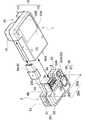
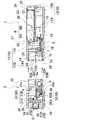
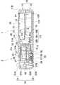
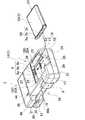
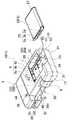
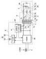
図1〜図10に、本発明の実施例1に係る充電器を示す。これらの図において、図1は実施例1に係る充電器を斜め上方から見た斜視図、図2は図1の充電器の使用状態を示す斜視図、図3は図1の充電器の充電部と装着部の脱着構造を示す分解斜視図、図4は図3の充電器を背面下側から見た斜視図、図5は図1に示す充電器の分解断面図、図6は図1の充電器の充電部と装着部の連結構造を示す断面図、図7は図1の充電器の内部構造を示す分解斜視図、図8は図1の充電器に電池パックを装着する状態を示す斜視図、図9は図1の充電器に他の電池パックを装着する状態を示す斜視図、図10は図1の充電器のブロック図を、それぞれ示している。 1 to 10 show a charger according to
これらの図に示す充電器は、充電対象の電池パック2を装着可能な装着部1と、この装着部1に装着された電池パック2に対して、所定の充電電力を供給するための充電回路40を有する充電部3とで構成している。充電器は、図3と図4に示すように、装着部1と充電部3とを着脱自在に連結できる構造としている。この充電器は、充電したい電池パック2を装着可能な装着部1を充電部3に装着すると共に、この装着部1に電池パック2を装着する状態で、充電部3から装着部1に充電電力を供給して電池パック2を充電する。さらに、この充電器は、異なるタイプの電池パック2を充電する場合には、この電池パック2を装着可能な装着部1に交換すると共に、この装着部1に電池パック2を装着する状態で充電部3から充電電力を供給して電池パック2を充電する。
さらに、本発明は、充電可能な電池パック2と、この電池パック2を脱着自在に装着可能であって、かつ、この電池パック2に対して所定の充電電力を供給する充電部3に脱着自在な装着部1とで電池パックユニットを構成して、充電部1に対して、電池パックユニットを交換することで、異なるタイプの電池パック2を充電することができる。
さらにまた、本発明は、電池パック2を脱着自在に装着可能な装着部1を、電池パック2を充電可能な充電部3を接続することで充電器を構成可能な電池パック装着ユニットとして、この装着部3に電池パック2を装着し、かつ充電部3と連結した状態で、充電部3から充電電力の供給を受けて、電池パック2を充電することもできる。
(装着部1)The charger shown in these drawings includes a mounting
Furthermore, the present invention can be removably attached to a
Furthermore, the present invention provides a battery pack mounting unit in which a
(Mounting part 1)
装着部1は、充電対象の電池パック2を脱着自在に装着すると共に、充電部3に脱着自在に連結されて、充電部3から供給される充電電力で電池パック2を充電する。装着部1は、充電部3に脱着自在に連結される装着ケース10を備えている。装着部1は、この装着ケース10の装着部側結合面10Aを、充電部3の充電部側結合面30Aに対向する姿勢として充電部3に連結される。装着部1は、充電部3に脱着自在に連結するために、装着ケース10の装着部側結合面10Aに、充電部3の連結凸部33を嵌入する連結凹部13を設けている。さらに、装着部1は、装着ケース10の上面に、電池パック2を装着するための電池装着凹部20を設けている。 The mounting
さらに、図の装着部1は、充電部3と電気的に接続するための装着部側コネクタ7と、電池装着部20にセットされる電池パック2の出力端子2Sに接触する接続端子8とを備えている。図の装着部1は、装着部側コネクタ7と接続端子8とをサブ回路基板6に固定しており、このサブ回路基板6を装着ケース10の内部に収納している。装着部1は、装着ケース10の定位置に配置されるサブ回路基板6を介して、装着部側コネクタ7を連結凹部13の内側に配置すると共に、接続端子8を電池装着凹部20の定位置に配置している。
ここで、電池パック装着ユニットを構成する装着部3は、充電対象の電池パック2を装着可能な電池装着凹部20と、充電部3に脱着自在に連結されて、電気的に接続するための装着部側コネクタ7とを備えて、電池装着凹部20に電池パック2を装着し、かつ装着部側コネクタ7を介して充電部3と連結する状態で、充電部3から所定の充電電力の供給を受けて、電池パック2を充電可能に構成することができる。
(装着ケース10)Further, the mounting
Here, the mounting
(Mounting case 10)
装着ケース10はプラスチック製で、平面形状を略四角形とする上ケース11と下ケース12とを別々に成形して連結している。上ケース11は、上面プレート11Aの周囲に周壁11Bを有する形状に成形しており、下ケース12は、下面プレート12Aの周囲に周壁12Bを有する形状に成形している。図の装着ケース10は、上ケース11と下ケース12とを対向する周壁11B、12Bで互いに連結して、内部に形成される収納室15にサブ回路基板6を収納している。
(連結凹部13)The mounting
(Connection recess 13)
連結凹部13は、装着ケース10の装着部側結合面10Aに設けた凹部であって、充電部3の充電部側結合面30Aに設けた連結凸部33を嵌入できる内形としている。装着ケース10は、装着部側結合面10Aには周壁11B、12Bを設けることなく、装着部側の端部を筒状として、充電部3の連結凸部33を挿入する連結凹部13を設けている。装着ケース10は、図3、図5、及び図6に示すように、連結凹部13に挿入される連結凸部33の先端面と対向する隔壁14を、装着部側結合面10Aよりも内側に位置して設けており、この隔壁14によって、上ケース11と下ケース12の内側を連結凹部13と収納室15とに区画している。この隔壁14は、上下に分割しており、上ケース11と下ケース12にそれぞれ一体成形して設けて互いに連結している。装着ケース10は、隔壁14の外側面と上ケース11の内面と下ケース12の内面とで形成される空間を連結凹部13としている。
(電池装着凹部20)The connecting
(Battery mounting recess 20)
電池装着凹部20は、上ケース11の上面に開口するように設けている。装着ケース10は、上ケース11の表面に凹部を設けて、この凹部を電池装着凹部20としている。電池装着凹部20は、充電対象となる特定の電池パック2を脱着自在に連結できる形状に成形している。図に示す装着部1は角形の電池パック2を装着するので、電池装着凹部20は、底面となる底プレート21を四角形として4辺に周壁を設けて、その開口部の内形を四角形としている。四角形の電池装着凹部20を形成する4辺の周壁は、電池パック2の端子面2Xと対向する第一壁22と、電池パック2の両側面と対向する一対の側壁23と、電池パック2の底面2Yと対向する第二壁24とからなり、これらの周壁を底プレート21に対して略垂直に成形している。この形状の電池装着凹部20は、電池パック2を抜けないようにセットできる。
(取出凹部25)The
(Removal recess 25)
さらに、図の装着ケース10は、第二壁24に、電池装着凹部20にセットされた電池パック2の取出凹部25を設けている。取出凹部25は、電池装着凹部20の上縁に向かって開口幅が広くなる形状としている。取出凹部25は、ここにユーザーが指等を入れて、電池パック2を簡単に取り出しできる。
(ひさし部26)Furthermore, the mounting
(Eave part 26)
さらに、上ケース11は、図5の断面図に示すように、電池パックの端子面と対向する第一壁22の上端縁にひさし部26を設けている。図の上ケース11は、四角形である電池装着凹部20の開口縁を内側に突出させてひさし部26としている。この構造によって、電池装着凹部20は、第一壁22をアンダーカット形状としている。アンダーカット形状の電池装着凹部20は、ここにセットした電池パック2の抜けを防止できる。とくに、第一壁22に設けた接続端子8で電池パック2の端子面2Xを、弾性的に押圧する状態での電池パック2の抜けを防止できる。さらに、第一壁22の上端にひさし部を設けることで、第一壁22から表出する接続端子8の露出を抑えて、ユーザーの指や異物などの接触を有効に防止しながら、埃等などからも保護できる。
(接続端子8)Further, as shown in the cross-sectional view of FIG. 5, the
(Connection terminal 8)
電池装着凹部20は、第一壁22に、電池パック2の出力端子2Sに接触する接続端子8を配置している。電池装着部20は、接続端子8を定位置に配置するために、接続端子8の金属線を出入りできるように案内するガイドスリット27を設けている。図4の電池装着凹部20は、第一壁22に、3列のガイドスリット27を、図において上下に伸びるように設けている。3列の接続端子8を定位置に配置するためである。第一壁22は、セットされる電池パック2の出力端子2Sに接触する位置に接続端子8を配置するようにガイドスリット27を設けている。ガイドスリット27は、その幅を、接続端子8の金属線の外径よりも広くして、金属線の接続端子8を自由に出入りできるようにガイドしている。 In the
接続端子8は、弾性変形できる金属線で、一端をサブ回路基板6にハンダ付けなどの方法で固定している。さらに、接続端子8は、金属線を折曲加工して、電池パック2の出力端子2Sに接触する接点部8Aと、この接点部8Aを弾性的に電池パック2の出力端子2Sに押圧する弾性アーム部8Bとを設けている。この接続端子8は、金属線を第二壁22のガイドスリット27に案内して、接点部8Aを弾性的に突出させて、電池パック2の出力端子2Sに弾性的に押圧する。図の接続端子8は、金属線の一端をサブ回路基板6に固定しているが、装着ケースに一端を固定して、接点部をガイドスリットから弾性的に突出する構造とすることもできる。装着ケースに固定される接続端子は、リード線(図示せず)を介してサブ回路基板に接続され、あるいは、連結凹部に配置される装着部側コネクタ(詳細には後述する)に接続されて電池パックを充電することができる。 The
装着部1は、充電対象となる電池パック2を電池装着凹部20にセットする状態で、第一壁22から表出する接続端子8を電池パック2の出力端子2Sに接触させて充電する。したがって、装着部1は、充電対象となる電池パック2の端子面2Xに設けた出力端子2Sと対向する位置に接続端子8を配置している。ここで、図に示す3列の接続端子8は、正負の充電端子8aと、温度検出端子8bとからなる。3列の接続端子8は、装着される電池パック2の出力端子2Sである正負の電極端子2aと、温度端子2bに対向して配置している。すなわち、正負の充電端子8aは正負の電極端子2aと対向する位置に、温度検出端子8bは温度端子2bと対向する位置に配置している。 The mounting
図8に示す電池パック2Aは、端子面2Xの片側に3つの出力端子2Sを並べて設けている。したがって、この電池パック2Aが装着される装着部1Aは、図に示すように、第一壁22Aの片側であって、電池パック2Aの出力端子2Sと対向する位置に3つの接続端子8を並べて配置している。 The
また、図9に示す電池パック2Bは、端子面2Xの片側(図において左側)に2つの出力端子2Sを設けて、その反対側(図において右側)に1つの出力端子2Sを設けている。したがって、この電池パック2Bが装着される装着部1Bの電池装着凹部20Bは、図に示すように、第一壁22Bの片側であって、電池パック2Bの2つの出力端子2Sと対向する位置に2つの接続端子8を並べて配置し、その反対側であって、電池パック2Bの1つの出力端子2Sと対向する位置に1つの接続端子8を配置している。 9 has two
さらに、図示しないが、装着部は、充電対象となる特定の電池パックを脱着自在に装着可能な電池装着凹部を設けると共に、この電池装着凹部の第一壁には、ここにセットされる電池パックの出力端子と対向する位置に接続端子を配置することにより、種々のタイプの電池パックを充電することができる。すなわち、装着部は、セットする電池パックの外形や構造に対応して、電池装着凹部の内形や大きさ、接続端子の形状や配置を変更して製造することにより、種々の電池パックを装着して充電できる。
(サブ回路基板6)Further, although not shown, the mounting portion is provided with a battery mounting recess capable of detachably mounting a specific battery pack to be charged, and the battery pack set here on the first wall of the battery mounting recess Various types of battery packs can be charged by disposing the connection terminal at a position facing the output terminal. That is, the mounting part can be mounted with various battery packs by changing the inner shape and size of the battery mounting recess and the shape and arrangement of the connection terminals according to the outer shape and structure of the battery pack to be set. Can be charged.
(Sub circuit board 6)
サブ回路基板6は、複数の接続端子8と装着部側コネクタ7とを定位置に固定している。このサブ回路基板6は、装着ケース10の内部の定位置に配置されて、各々の接続端子8を電池装着凹部20の第一壁22のガイドスリット27から表出させると共に、装着部側コネクタ7を連結凹部13の内側に配置している。すなわち、複数の接続端子8と装着部側コネクタ7とをサブ回路基板6を介して装着ケース10の定位置に配置している。この構造は、複数の接続端子8と装着部側コネクタ7の両方を直接にサブ回路基板6に固定し、複数の接続端子8と装着部側コネクタ7と回路基板4とを組立アッセンブリーとして、装着ケース10に配置できるので、能率よく簡単に組み立てできる特徴がある。ただ、装着部は、必ずしもサブ回路基板を備える必要はなく、装着部側コネクタと接続端子とを直接に装着ケースに固定して、これらをリード線等で電気接続することもできる。 The
図5ないし図7の装着ケース10は、収納室15内の定位置にサブ回路基板6を配置するために、サブ回路基板6を貫通して定位置に連結する位置決めリブ16を上ケース11に一体成形して設けている。一方、サブ回路基板6には、この位置決めリブ16を連結するために連結穴6Aを設けている。図の位置決めリブ16は、サブ回路基板6の連結穴6Aに挿入される挿入部16Aを下端に設けると共に、下端部を段差形状として、この段差部16Bをサブ回路基板6の上面に当接させて保持する形状としている。さらに、図5に示す上ケース11は、サブ回路基板6に固定された接続端子8の固定部を保護する補強リブ17を、電池装着凹部20の底プレート21から下方に突出して一体成形して設けており、この補強リブ17の下端もサブ回路基板6の上面に当接させてサブ回路基板6を保持する構造としている。さらに、下ケース12は、サブ回路基板6の下面に当接して、サブ回路基板6を所定の位置に支持する支持リブ18を設けている。以上の構造は、位置決めリブ16の挿入部16Aをサブ回路基板6の連結穴6Aに挿入してサブ回路基板6を定位置に位置決めしながら、位置決めリブ16の段差部16B及び補強リブ17と支持リブ18とでサブ回路基板6を上下から挟着する状態で保持して装着ケース10の定位置に配置できる。ただ、サブ回路基板は、図示しないが、嵌合構造や係止構造、ネジ止め等により装着ケース内の定位置に配置することもできる。
(装着部側コネクタ7)The mounting
(Mounting side connector 7)
装着部側コネクタ7は、連結凹部13の内側に表出する状態で固定している。この装着部側コネクタ7は、連結凹部13に挿入される連結凸部33に設けた充電部側コネクタ5が接続されて充電部3に電気接続される。充電部側コネクタ5に接続される装着部側コネクタ7は、充電部3の充電回路40から電池パック2の充電電力が供給される。装着部側コネクタ7に供給される充電電力は、サブ回路基板6を介して接続端子8の充電端子8aに供給されると共に、充電端子8aに接触する電極端子2aを介して電池パック2に供給されて電池パック2を充電する。さらに、装着部側コネクタ7は、電池パック2の温度端子2bに接触する温度検出端子8bからの信号を充電部側コネクタ5を介して充電部1側に伝送する。 The mounting
図に示す装着部側コネクタ7は、雌型のコネクタで、連結凸部33に固定された雄型のコネクタである充電部側コネクタ5に係合されて互いに電気接続するようにしている。雌型のコネクタである装着部側コネクタ7は、互いに平行な姿勢で配列された複数の絶縁プレート7Aの間に接触端子7aを設けている。この装着部側コネクタ7は、隣接する絶縁プレート7Aの間に雄型のコネクタである充電部側コネクタ5の出力端子板5aが挿入されて、接触端子7aと出力端子板5aが電気接続される。このように、装着部側コネクタ7を雌型のコネクタとする構造は、装着部1の電池装着凹部13に電池パック2を装着する状態で、電池パック2の電力が装着部側コネクタ7を介して外部に漏れる弊害、例えば、連結凹部13の内側に表出する装着部側コネクタ7にユーザーの指が接触して感電したり、異物が接触して電池パック2がショートする等の弊害を確実に防止できる。 The mounting
図5と図7に示す装着部側コネクタ7は、サブ回路基板6の端部に固定されており、サブ回路基板6を装着ケース10の収納室15に配置する状態で、隔壁14に開口して設けたコネクタ窓14Aから外部に表出させて連結凹部13の内側に配置している。図3と図7に示す下ケース12は、装着部側コネクタ7をコネクタ窓14Aの定位置に固定するために、隔壁14をコネクタ窓14Aの両側で外側に折曲して折曲部14Bを設けており、対向する折曲部14Bの間に装着部側コネクタ7を嵌入するようにしている。さらに、図に示す装着部側コネクタ7は、ケーシングの両側に、下ケース12に連結するための嵌合凸部7Bを突出して設けている。この装着部側コネクタ7は、両側の嵌合凸部7Bを隔壁14の折曲部14Bに設けた位置決め凹部14bに嵌入して下ケース12の定位置に固定している。
(充電部3)The mounting
(Charging unit 3)
充電部3は、装着部1が脱着自在に連結されて、装着部1にセットされた電池パック2を充電する充電電力を装着部1に供給して電池パック2を充電する。充電部3は、外形を箱状とする本体ケース30を備えている。充電部3は、この本体ケース30の充電部側結合面30Aに、装着部1の装着部側結合面10Aを対向させる姿勢として装着部1を連結させる。充電部3は、装着部1を脱着自在に連結するために、本体ケース30の充電部側結合面30Aに、装着部1の連結凹部13に嵌入される連結凸部33を設けている。 The charging
さらに、充電部3は、装着部1に装着された電池パック2に対して、所定の充電電力を供給して充電する充電回路40と、電池パック2を充電するための充電電力を外部から受けるためのコネクタ9と、装着部1と電気的に接続するための充電部側コネクタ5とを備えている。図5ないし図7、及び図10に示す充電部3は、充電回路40を実現する電子部品を実装してなる回路基板4を備えており、この回路基板4を本体ケース30の内部に収納している。回路基板4は、ケーブル49を介してコネクタ9を接続すると共に、一端に充電部側コネクタ5を固定して、連結凸部33の定位置に配置している。
(本体ケース30)Further, the charging
(Main body case 30)
本体ケース30は、プラスチック製の第1ケース31と第2ケース32とからなる。第1ケース31は、第1表面プレート31Aの周囲に外周壁31Bを一体的に成形しており、第2ケース32は、第2表面プレート32Aの周囲に外周壁32Bを一体的に成形している。図の本体ケースは、第1ケース31と第2ケース32とを対向する外周壁31B、32Bで互いに連結して、全体の形状を箱形としている。
(連結凸部33)The
(Connecting convex part 33)
連結凸部33は、本体ケース30の充電部側結合面30Aから突出する凸部で、装着部1の装着部側結合面10Aに設けた連結凹部13に嵌入できる外形としている。図3ないし図9の本体ケース30は、第1ケース31と第2ケース32を連結して、充電部側結合面30Aから突出する連結凸部33を一体的に成形して設けている。連結凸部33は、第1表面プレート31Aの突出部31aと第2表面プレート32の突出部32aとを周囲の外周壁31B、32Bで連結して、充電部側結合面30Aから突出する形状としている。 The connection
図4の充電部3は、本体ケース30の充電部側結合面30Aに、連結凸部33を設けてなる連結領域30aと、連結凸部33を設けない非連結領域30bとを設けて、連結領域30aを装着部1の装着部側結合面10Aに対向させている。図4の本体ケース30は、長方形の充電部側結合面30Aの長手方向の端部に非連結領域30bを設けている。図の充電器は、充電部3の充電部側結合面30Aの長手方向の長さを装着部1の装着部側結合面10Aの長手方向の長さよりも長くすると共に、充電部3の充電部側結合面30Aの短手方向の長さを装着部1の装着部側結合面10Aの短手方向の長さとほぼ等しくしている。この充電器は、図1に示すように、充電部3に装着部1を連結する状態で、充電部3と装着部1との外周面が同一面となるように、具体的には、充電部3と装着部1との連結部分における上面、下面、及び一方の側面が同一平面となるようにしている。したがって、充電部3の連結凸部33は、装着部1の装着部側結合面10Aの外周よりもひとまわり小さな外形として、装着部1の連結凹部13に嵌入できるようにしている。
(収納スペース35)The charging
(Storage space 35)
さらに、本体ケース30は、内部に形成される収納スペース35に回路基板4を収納している。図に示す本体ケース30は、第1ケース31の内側と第2ケース32の内側に、互いに連結される区画壁34を設けており、この区画壁34と外周壁31B、32Bの内側に回路基板4の収納スペース35を設けている。この区画壁34は、上下に分割しており、第1ケース31と第2ケース32にそれぞれ一体成形して設けて互いに連結している。図7の本体ケース30は、充電部側結合面30Aと反対側の端面と、非連結領域側20bの側面に沿って区画壁34を設けている。すなわち、図の本体ケース30は、連結凸部33を形成する外周壁31B、32Bと、連結領域30a側の側面の外周壁31B、32Bと、区画壁34との内側に回路基板4の収納スペース35を設けている。 Further, the
さらに、図の本体ケース30は、回路基板4を定位置に配置するために、収納スペース35を形成する外周壁31B、32Bと区画壁34の内周面に複数の位置決めリブ36、37を設けている。図の位置決めリブ36、37は、回路基板4の外周縁に交差する姿勢で設けており、これらの位置決めリブ36、37の内面に回路基板4の外周縁を対向する姿勢で配置して、回路基板4を収納スペース35の定位置に位置決めしている。さらに、位置決めリブ37は、段差形状に成形しており、この段差部37Bを回路基板4の表面に当接させて、回路基板4の上面と下面を支持する支持部としている。以上の構造は、位置決めリブ36、37で回路基板4の外周縁を位置決めしながら、位置決めリブ37の段差部37Bで回路基板4を上下から挟着する状態で保持して本体ケース30の定位置に配置している。ただ、回路基板は、図示しないが、嵌合構造や係止構造、ネジ止め等により本体ケース内の定位置に配置することもできる。
(回路基板4)Further, the
(Circuit board 4)
充電部3は、図10のブロック図に示すように、コネクタ9を介して外部電源から供給される電力で電池パック2を充電する充電回路40と、電池パック2から入力される電池温度と電池電圧とから電池パック2の充電を制御する保護回路41と、電池パック2の充電状態や異常を外部に表示する表示部42とを備えている。したがって、回路基板4は、これらの回路を実現する電子部品を実装している。 As shown in the block diagram of FIG. 10, the charging
充電回路40は、外部電源に接続されるコネクタ9から供給される電力を、電池パック2を充電する充電電力に変換して出力する。電池パック2をリチウムイオン電池とする充電器にあっては、この充電回路40が定電流定電圧充電して電池パック2を充電する。また、電池パックをニッケル水素電池やニッケルカドミウム電池とする充電器にあっては、充電回路が定電流充電して電池パックを充電する。さらに、充電回路40は、電池パック2の満充電を検出して充電を停止する。 The charging
保護回路41は、電池温度と電池電圧を検出して電池パック2を保護しながら充電をコントロールする。電池温度は、電池パック2に内蔵される温度センサ46で検出されて、電池パック2の端子面2Xに設けた温度端子2bから出力される信号から検出する。保護回路41は、電池パック2の充電電流を制限する温度を記憶するメモリ43を備えている。メモリ43は、電池温度に対する許容電流を記憶している。許容電流は、その温度において電池パック2に流すことができる最大電流であって、この電流よりも少ない電流で使用される。したがって、保護回路41は、電池温度から電池パック2を充電する電流を許容電流よりも小さく制御して電池パック2を保護する。また、保護回路は、電池パックの充電を許容する最高温度と最低温度を記憶して、この最高温度と最低温度との間で充電を許容するように制御することもできる。最高温度と最低温度は、電池の種類により最適温度に設定され、たとえばリチウムイオン電池においては、最高温度を約60℃〜70℃、最低温度を約−10℃〜0℃とすることができる。 The
さらに、保護回路41は、電池パック2の電圧を検出して充電を制御する。この保護回路41は、充電している電池パック2の電圧が最高電圧まで上昇すると充電を停止する。図10に示す保護回路41は、電池温度や電池電圧の異常を検出すると、充電回路40を制御して電池パック2の充電を停止する。 Furthermore, the
表示部42は、充電回路40や保護回路41から電池パック2の充電状態や異常等を示す信号が入力されて、このことを外部に表示する。図に示す表示部42は、光源である発光ダイオード44と、この発光ダイオード44の点灯状態を制御する点灯回路45とを備えている。表示部42は、充電回路40が電池パック2を充電する状態と、電池パック2が満充電となって充電を停止する状態とを検出して、点灯回路45が発光ダイオード44を点灯させる。点灯回路45は、電池パック2の充電が開始されると、発光ダイオード44を点灯させて充電中であることを表示し、電池パック2が満充電されると発光ダイオード44を消灯させて充電が完了したことを表示する。さらに、点灯回路45は、電池パック2の電圧が異常に上昇し、あるいは、電池温度が異常に上昇する状態では、電池パック2の異常として発光ダイオード44を点滅させる。この表示部42は、単色の発光ダイオード44の点灯状態を制御して、電池パック2の充電状態や異常等を表示できる。 The
ただ、表示部は、電池パックの充電状態や異常を、発光ダイオードの発光色を変化させて表示することもできる。例えば、表示部は、電池パックの充電中においては、発光ダイオードをオレンジ色に発光させると共に、電池パックの残容量に応じて発光ダイオードの点滅周期を変更させることもできる。この表示部は、電池パックが満充電に近づくにつれて発光ダイオードの点滅周期を短くして充電状態をユーザーに表示することができる。さらに、電池パックが満充電されると、緑色に点灯させて電池パックが満充電されたことを表示できる。また、電池の異常時には、他の色に点滅させ、あるいは多色に点滅させて、あるいはまた、特定の点滅パターンで点滅させてこのことを表示することもできる。 However, the display unit can also display the state of charge or abnormality of the battery pack by changing the emission color of the light emitting diode. For example, the display unit can cause the light emitting diode to emit orange light while the battery pack is being charged, and can change the blinking cycle of the light emitting diode according to the remaining capacity of the battery pack. This display unit can display the state of charge to the user by shortening the blinking cycle of the light emitting diode as the battery pack approaches full charge. Further, when the battery pack is fully charged, it can be lit in green to indicate that the battery pack is fully charged. Further, when the battery is abnormal, this can be displayed by blinking in another color, blinking in multiple colors, or blinking in a specific blinking pattern.
図9に示す回路基板4は、上面に発光ダイオード44を固定している。本体ケース30は、上ケース31に発光ダイオード44の開口窓38を設けており、この開口窓38から発光ダイオード44を表出させて外部に表示している。ただ、本体ケースは、発光ダイオードを表出させる開口窓を設けることなく、発光ダイオードの発光を透過させて外部に表示することもできる。このケースは、透光性を有するプラスチックで製作する。とくに、このケースは、発光ダイオードと対向する部分を薄く成形して、発光ダイオードから照射される光を外部に透過する透光部を設けて、効率よく外部に発光させることもできる。
(充電部側コネクタ5)The
(Charging unit side connector 5)
さらに、充電部3は、充電回路40の出力側に、充電部側コネクタ5を接続している。図5と図7に示す充電部側コネクタ5は、回路基板4の端部に固定されており、回路基板4を本体ケース30の収納スペース35に配置する状態で、連結凸部33の下面側に設けた収納凹部33Aに表出する状態で配置している。この充電部側コネクタ5は、連結凸部33を連結凹部13に挿入する状態で、連結凹部13に設けた装着部側コネクタ7に接続されて装着部1に電気接続される。装着部側コネクタ7に接続される充電部側コネクタ5は、充電回路40から出力される充電電力を装着部1側に供給する。さらに、この充電部側コネクタ5は、電池パック2の温度端子2bからの信号を充電部側コネクタ5を介して受け取る。 Further, the charging
図に示す充電部側コネクタ5は、収納凹部33Aに開口して設けたコネクタ窓33Bから外部に表出させて収納凹部33Aの内側に配置している。図の第2ケース32は、充電部側コネクタ5を収納凹部33Aの定位置に固定するために、外周壁32Bにコネクタ窓33Bを開口すると共に、充電部側コネクタ5の収納スペース35側の端面に当接する支持凸部39を一体成形して設けている。充電部側コネクタ5は、両側面がコネクタ窓33Bの開口縁で位置決めされると共に、後端面が支持凸部39で支持されて第2ケース32の定位置に配置される。 The charging
図に示す充電部側コネクタ5は、雄型のコネクタで、連結凹部13に固定された雌型のコネクタである装着部側コネクタ7に係合されて互いに電気接続するようにしている。雄型のコネクタである充電部側コネクタ5は、互いに平行な姿勢で配列された複数の出力端子板5aを備えている。図に示す連結凸部33は、外部に表出する充電部側コネクタ5を保護するために、充電部側コネクタ5の上側をカバーするカバー壁33Cを第1ケース31に一体成形して設けている。図のカバー壁33Cは、充電部側コネクタ5を構成する複数の出力端子板5aの上面に沿って設けている。充電部側コネクタ5は、下面側の収納凹部33Aに配置されると共に、このカバー壁33Cによって上面側がカバーされて、上方からの異物によるショート等を有効に防止している。
(コネクタ9)The charging
(Connector 9)
さらに、充電部3は、充電回路40の入力側に、ケーブル49を介してコネクタ9を接続している。コネクタ9は、規格化されたコネクタで、従来のように、ACアダプタ等の外部電源を用意することなく、簡単に給電できるようにしている。図に示すコネクタ9は、USBコネクタ9Aとしている。USBコネクタ9Aであるコネクタ9は、USBの給電ポートを外部電源として利用する。コネクタ9は、外部電源に接続される状態で、外部電源から供給される電力をケーブル49を介して回路基板4の充電回路40に供給する。ただし、コネクタは必ずしもUSBコネクタとする必要はなく、電源から電力が供給される他の全ての構造とすることができる。たとえば、充電部は、外部接続されるACアダプタから給電することもできる。さらに、充電部は、商用電源のコンセントに接続されるプラグ刃を備えて、このプラグ刃から供給される交流電力を直流に変換して電池パックを充電することもできる。この充電部は、供給される交流電力を直流電力に変換する整流回路を備えて、整流回路で変換された直流電力を、電池パックを充電できる充電電力に充電回路で変換して出力する。
(ケーブル49)Further, the charging
(Cable 49)
ケーブル49は、可撓性を有しており、後端を本体ケース30の内部に挿入して回路基板4に接続すると共に、先端にはコネクタ9を接続して、本体ケース30から外部に引き出している。本体ケース30の外部に引き出されたケーブル49は、本体ケース30の外周壁31B、32Bに設けた外周溝51に案内している。図の本体ケース30は、装着部1と反対側の端面と、非連結領域側20bの側面とに外周溝51を設けている。外周溝51は、ケーブル49を案内する断面形状の溝形としている。この構造は、本体ケース30の外形を大きくすることなく、本体ケース30の外周に沿って外周溝51を設けて、ケーブル49をコンパクトに収納できる。 The
さらに、図の装着ケース10は、装着部側結合面10Aと反対側の端部において、充電部3の充電部側結合面30Aの非連結領域30bと対向する突出部1Tを設けており、この突出部1Tに、コネクタ9の先端部を嵌入するコネクタ嵌入凹部29を設けている。図の突出部1Tは、充電部3側の対向面であって、非連結領域30bと対向する面にコネクタ嵌入凹部29を設けている。この構造は、図1に示すように、電池パックを充電しない状態において、コネクタ9の先端部をコネクタ嵌入凹部29に挿入することで、コネクタ9の先端部を保護できる。ケーブル49は、コネクタ9をコネクタ嵌入凹部29に案内する状態で、外周溝51の外部にはみ出すことなく、外周溝51内に収納できる長さとしている。 Furthermore, the mounting
さらに、図に示す充電器は、充電部3の非連結領域30b側の側部と、装着部1の端部に設けた突出部1Tとを、装着部1の側面1Sから突出させることにより、充電器の側面1Sに凹部50を形成している。この充電器は、図1に示すように、電池パックを充電しない状態において、本体ケース30の外周溝51にケーブル49を収納しながら、コネクタ9の先端部を装着ケース10のコネクタ嵌入凹部29に挿入して、コネクタ8を充電器の側面1Sに形成される凹部50にコンパクトに収納できる。とくに、可撓性のあるケーブル49とコネクタ9とを充電器の外側にはみ出させることなく、外観良く収納しながら、ケーブル49とコネクタ9とを保護できる。
(挿入ガイド52)Furthermore, the charger shown in the figure protrudes from the
(Insertion guide 52)
さらに、充電器は、充電部3の連結凸部33と装着部1の連結凹部13とに、連結凸部33を正しい姿勢で連結凹部13に挿入するための挿入ガイド52を設けている。図に示す連結凸部33と連結凹部13は、連結凸部33の挿入方向に延びる複数の挿入ガイド52を設けている。図3と図4に示す挿入ガイド52は、連結凸部33の表面に設けたガイド溝53と、装着部1の連結凹部13の内面に設けたガイド凸条54とからなる。図に示す連結凸部33は、上面と下面の両側にそれぞれガイド溝53を設けている。また、装着部1も連結凹部13の内面であって、上面と下面の両側部にそれぞれガイド凸条54を設けている。連結凸部33のガイド溝53と連結凹部13のガイド凸条54は、互いに対向する位置に設けており、ガイド溝53にガイド凸条54を案内する状態で連結凸部33を連結凹部13に挿入できるようにしている。このように、挿入ガイド52を介して連結凸部33を連結凹部13に挿入する構造は、互いに係合される装着部側コネクタ7と充電部側コネクタ5とを正しい方向に接触させて接触不良を低減できる。図に示すガイド溝53とガイド凸条54は連結凸部33に対して左右を非対称に設けており、連結凸部33が逆向きに連結凹部13に挿入されるのを防止している。
(係止機構55)Further, the charger is provided with an insertion guide 52 for inserting the connection
(Locking mechanism 55)
さらに、図4と図6に示す連結凸部33は、下面側に設けられるガイド溝53の一方を幅広に成形しており、この幅広のガイド溝53Aを、連結凸部33と連結凹部13の係止機構55に併用している。この係止機構55は、連結凹部13に挿入された連結凸部33を係止して、連結凸部33が連結凹部13から抜けるのを防止する。図に示す係止機構55は、幅広のガイド溝53A内に配設されて、連結凸部33の表面(図において下面)に対して出入り自在に配置された係止フック56と、この係止フック56を一端に有すると共に、ユーザーに押されて、この係止フック56を連結凸部33の内部に向かって移動させる操作部57と、この操作部57を係止フック56の突出方向に弾性的に押し出して、係止フック56を幅広のガイド溝53A内に突出させる弾性体58と、連結凹部13の内面に設けられると共に、幅広のガイド溝53A内に案内されて係止フック56が係止される係止凸部59とで構成している。 Further, the connecting
この係止機構55は、連結凸部33を連結凹部13に案内する状態で、係止凸部59が幅広のガイド溝53Aに案内される。幅広のガイド溝53A内において、係止フック56と係止凸部59は、互いに対向する傾斜面に沿って摺動し、連結凸部33を連結凹部13に完全に挿入する状態では、係止フック56が係止凸部59に係止される。この状態で、連結凸部33は、連結凹部13に抜けない状態で連結される。連結凸部33を連結凹部13から引き抜く時には、操作部57を押して係止フック56と係止凸部59との係止状態を解除した状態で、装着部1と充電部3とを離して連結凸部33を連結凹部13から引き抜く。 In this
1…装着部 1A…装着部
1B…装着部
1S…側面
1T…突出部
2…電池パック 2A…電池パック
2B…電池パック
2S…出力端子
2a…電極端子
2b…温度端子
2X…端子面
2Y…底面
3…充電部
4…回路基板
5…充電部側コネクタ 5a…出力端子板
6…サブ回路基板 6A…連結穴
7…装着部側コネクタ 7A…絶縁プレート
7a…接触端子
7B…嵌合凸部
8…接続端子 8A…接点部
8B…弾性アーム部
8a…充電端子
8b…温度検出端子
9…コネクタ 9A…USBコネクタ
10…装着ケース 10A…装着部側結合面
11…上ケース 11A…上面プレート
11B…周壁
12…下ケース 12A…下面プレート
12B…周壁
13…連結凹部
14…隔壁 14A…コネクタ窓
14B…折曲部
14b…位置決め凹部
15…収納室
16…位置決めリブ 16A…挿入部
16B…段差部
17…補強リブ
18…支持リブ
20…電池装着凹部 20A…電池装着部
20B…電池装着部
21…底プレート
22…第一壁 22A…第一壁
22B…第一壁
23…側壁
24…第二壁
25…取出凹部
26…ひさし部
27…ガイドスリット
29…コネクタ嵌入凹部
30…本体ケース 30A…充電部側結合面
30a…連結領域
30b…非連結領域
31…第1ケース 31A…第1表面プレート
31a…突出部
31B…外周壁
32…第2ケース 32A…第2表面プレート
32a…突出部
32B…外周壁
33…連結凸部 33A…収納凹部
33B…コネクタ窓
33C…カバー壁
34…区画壁
35…収納スペース
36…位置決めリブ
37…位置決めリブ 37B…段差部
38…開口窓
39…支持凸部
40…充電回路
41…保護回路
42…表示部
43…メモリ
44…発光ダイオード
45…点灯回路
46…温度センサ
49…ケーブル
50…凹部
51…外周溝
52…挿入ガイド
53…ガイド溝 53A…幅広のガイド溝
54…ガイド凸条
55…係止機構
56…係止フック
57…操作部
58…弾性体
59…係止凸部1 ... Mounting
1B ... Wearing part
1S ... side
1T ... protruding
2B ... Battery pack
2S ... Output terminal
2a ... Electrode terminal
2b ... Temperature terminal
2X ... Terminal surface
2Y ...
7a ... Contact terminal
7B ... Fitting
8B ... Elastic arm
8a ... Charging terminal
8b ...
11B ...
12B ...
14B ... Bent part
14b ... Positioning
16B ... Step
20B ...
22B ...
26 ...
30a ... Connection area
30b ...
31a ... protrusion
31B ... outer
32a ... Projection
32B ... Outer
33B ... Connector window
33C ...
Claims (9)
Translated fromJapanese充電対象の電池パックを装着可能な装着部と、
前記装着部に装着された電池パックに対して、所定の充電電力を供給するための充電回路を有する充電部と、
を備えており、
前記装着部と前記充電部とを着脱式に構成してなることを特徴とする充電器。A charger capable of charging a battery pack,
A mounting part on which a battery pack to be charged can be mounted;
A charging unit having a charging circuit for supplying predetermined charging power to the battery pack mounted on the mounting unit,
With
A battery charger characterized in that the mounting portion and the charging portion are configured to be detachable.
前記充電部が、電池パックを充電するための充電電力を外部から受けるためのコネクタを有しており、
該コネクタが、規格化されたコネクタであることを特徴とする電池パック。The charger according to claim 1,
The charging unit has a connector for receiving charging power from the outside for charging the battery pack,
A battery pack, wherein the connector is a standardized connector.
前記コネクタが、USBコネクタであることを特徴とする電池パック。The charger according to claim 2,
The battery pack is characterized in that the connector is a USB connector.
前記充電部は、前記USBコネクタを、可撓性を有するケーブルを介して前記充電部から引き出しており、
前記装着部は、前記USBコネクタを嵌入するためのコネクタ嵌入凹部を備えてなることを特徴とする充電器。The charger according to claim 3,
The charging unit pulls out the USB connector from the charging unit via a flexible cable,
The charger is characterized in that the mounting portion includes a connector insertion recess for inserting the USB connector.
前記充電部は、外形を箱状とし、該箱状の長方形状の一面を、前記装着部と結合させるための充電部側結合面としており、
前記装着部は、
前記充電部と結合させるための装着部側結合面を、前記充電部側結合面よりも長手方向を短く形成し、短手方向を該充電部側結合面と略等しくしており、
前記装着部側結合面と対向する端面を、前記充電部側結合面と略等しくしており、
前記充電部と前記装着部とを結合させた状態で、充電器の側面に凹部を形成させ、
該凹部に、前記USBコネクタを配置するよう構成してなることを特徴とする充電器。The charger according to claim 4,
The charging unit has a box-like outer shape, and has one side of the box-like rectangular shape as a charging unit side coupling surface for coupling with the mounting unit,
The mounting part is
The mounting part side coupling surface for coupling with the charging unit is formed to have a shorter longitudinal direction than the charging unit side coupling surface, and the short side direction is substantially equal to the charging unit side coupling surface,
The end face facing the mounting part side coupling surface is substantially equal to the charging part side coupling surface,
In a state where the charging unit and the mounting unit are combined, a concave portion is formed on the side surface of the charger,
A charger configured to dispose the USB connector in the recess.
前記充電部は、前記装着部と電気的に接続するための充電部側コネクタを備えており、
前記装着部は、前記充電部と電気的に接続するための装着部側コネクタを備えており、
前記装着部側コネクタを雌型とし、前記充電部側コネクタを雄型として、該装着部側コネクタと充電部側コネクタとを係合させるよう構成してなることを特徴とする充電器。The charger according to any one of claims 2 to 5,
The charging unit includes a charging unit side connector for electrically connecting to the mounting unit,
The mounting portion includes a mounting portion side connector for electrically connecting to the charging portion,
The charger is characterized in that the mounting portion side connector is a female type and the charging portion side connector is a male type, and the mounting portion side connector and the charging portion side connector are engaged with each other.
前記装着部は、電池パックを所定の姿勢で配置するための電池装着凹部を設けており、
前記電池装着凹部は、電池パックを装着した状態で、該電池パックの周囲を囲む壁部を設けており、
前記壁部は、
電池パックの電極端子を設けた端子面側と面する第一壁と、
前記第一壁と対向させて、電池パックの端子面と対向する底面側と面する第二壁と、
を有しており、
前記第一壁は、電池パックを前記電池装着凹部に装着した状態で、端子面を覆うように迫り出す形状に突出させたひさし部を設けており、
前記第二壁は、電池パックを前記電池装着凹部に装着した状態で、底面を表出させる取出凹部を設けてなることを特徴とする充電器。The charger according to any one of claims 1 to 6,
The mounting portion is provided with a battery mounting recess for placing the battery pack in a predetermined posture,
The battery mounting recess has a wall portion surrounding the battery pack in a state where the battery pack is mounted,
The wall is
A first wall facing a terminal surface side provided with electrode terminals of the battery pack;
A second wall facing the first wall and facing the bottom side facing the terminal surface of the battery pack;
Have
The first wall is provided with an eaves portion projecting into a shape that protrudes so as to cover the terminal surface with the battery pack mounted in the battery mounting recess,
The charger is characterized in that the second wall is provided with an extraction recess that exposes the bottom surface in a state where the battery pack is mounted in the battery mounting recess.
充電対象の電池パックを装着可能な電池装着凹部と、
充電部と脱着自在に連結すると共に、電気的に接続するための装着部側コネクタと、
を備えており、
前記電池装着凹部に電池パックを装着し、かつ前記装着部側コネクタを介して充電部と連結した状態で、該充電部から所定の充電電力の供給を受けて、電池パックを充電可能に構成してなることを特徴とする電池パック装着ユニット。A battery pack mounting unit capable of configuring a charger by connecting a charging unit capable of charging the battery pack,
A battery mounting recess capable of mounting a battery pack to be charged;
A detachable connection with the charging part, and a mounting part side connector for electrical connection,
With
A battery pack is mounted in the battery mounting recess and connected to a charging unit via the mounting unit side connector, and is supplied with a predetermined charging power from the charging unit, so that the battery pack can be charged. A battery pack mounting unit.
前記電池パックを装着可能であって、かつ、該電池パックに対して所定の充電電力を供給する充電部に脱着自在に連結される装着部と、
を備えており、
前記装着部に前記電池パックを装着すると共に、該装着部を前記充電部に連結して該電池パックを充電するようにしてなる電池パックユニット。A rechargeable battery pack;
A mounting portion that can be mounted on the battery pack and is detachably connected to a charging portion that supplies predetermined charging power to the battery pack;
With
A battery pack unit configured to mount the battery pack on the mounting portion and connect the mounting portion to the charging portion to charge the battery pack.
Priority Applications (2)
| Application Number | Priority Date | Filing Date | Title |
|---|---|---|---|
| JP2011239785AJP2013099120A (en) | 2011-10-31 | 2011-10-31 | Charger, battery pack attachment unit, and battery pack unit |
| US13/440,144US20130106352A1 (en) | 2011-10-31 | 2012-04-05 | Battery charger, battery pack docking module, and battery pack module |
Applications Claiming Priority (1)
| Application Number | Priority Date | Filing Date | Title |
|---|---|---|---|
| JP2011239785AJP2013099120A (en) | 2011-10-31 | 2011-10-31 | Charger, battery pack attachment unit, and battery pack unit |
Publications (1)
| Publication Number | Publication Date |
|---|---|
| JP2013099120Atrue JP2013099120A (en) | 2013-05-20 |
Family
ID=48171713
Family Applications (1)
| Application Number | Title | Priority Date | Filing Date |
|---|---|---|---|
| JP2011239785APendingJP2013099120A (en) | 2011-10-31 | 2011-10-31 | Charger, battery pack attachment unit, and battery pack unit |
Country Status (2)
| Country | Link |
|---|---|
| US (1) | US20130106352A1 (en) |
| JP (1) | JP2013099120A (en) |
Cited By (6)
| Publication number | Priority date | Publication date | Assignee | Title |
|---|---|---|---|---|
| WO2015063995A1 (en)* | 2013-10-30 | 2015-05-07 | 三洋電機株式会社 | Portable power supply |
| JP2017103924A (en)* | 2015-12-02 | 2017-06-08 | ホライズン株式会社 | Charge cable |
| JP6190989B1 (en)* | 2016-06-03 | 2017-08-30 | ソフトバンクコマース&サービス株式会社 | Charger |
| WO2017179765A1 (en)* | 2016-04-12 | 2017-10-19 | Lg Electronics Inc. | Battery charger and battery pack |
| WO2017208473A1 (en)* | 2016-06-03 | 2017-12-07 | ソフトバンクコマース&サービス株式会社 | Charging device |
| JP2019134641A (en)* | 2018-02-02 | 2019-08-08 | 株式会社エンビジョンAescエナジーデバイス | Charger |
Families Citing this family (394)
| Publication number | Priority date | Publication date | Assignee | Title |
|---|---|---|---|---|
| US9060770B2 (en) | 2003-05-20 | 2015-06-23 | Ethicon Endo-Surgery, Inc. | Robotically-driven surgical instrument with E-beam driver |
| US20070084897A1 (en) | 2003-05-20 | 2007-04-19 | Shelton Frederick E Iv | Articulating surgical stapling instrument incorporating a two-piece e-beam firing mechanism |
| US9072535B2 (en) | 2011-05-27 | 2015-07-07 | Ethicon Endo-Surgery, Inc. | Surgical stapling instruments with rotatable staple deployment arrangements |
| US11998198B2 (en) | 2004-07-28 | 2024-06-04 | Cilag Gmbh International | Surgical stapling instrument incorporating a two-piece E-beam firing mechanism |
| US8215531B2 (en) | 2004-07-28 | 2012-07-10 | Ethicon Endo-Surgery, Inc. | Surgical stapling instrument having a medical substance dispenser |
| US11890012B2 (en) | 2004-07-28 | 2024-02-06 | Cilag Gmbh International | Staple cartridge comprising cartridge body and attached support |
| US11484312B2 (en) | 2005-08-31 | 2022-11-01 | Cilag Gmbh International | Staple cartridge comprising a staple driver arrangement |
| US10159482B2 (en) | 2005-08-31 | 2018-12-25 | Ethicon Llc | Fastener cartridge assembly comprising a fixed anvil and different staple heights |
| US11246590B2 (en) | 2005-08-31 | 2022-02-15 | Cilag Gmbh International | Staple cartridge including staple drivers having different unfired heights |
| US7934630B2 (en) | 2005-08-31 | 2011-05-03 | Ethicon Endo-Surgery, Inc. | Staple cartridges for forming staples having differing formed staple heights |
| US7669746B2 (en) | 2005-08-31 | 2010-03-02 | Ethicon Endo-Surgery, Inc. | Staple cartridges for forming staples having differing formed staple heights |
| US9237891B2 (en) | 2005-08-31 | 2016-01-19 | Ethicon Endo-Surgery, Inc. | Robotically-controlled surgical stapling devices that produce formed staples having different lengths |
| US20070106317A1 (en) | 2005-11-09 | 2007-05-10 | Shelton Frederick E Iv | Hydraulically and electrically actuated articulation joints for surgical instruments |
| US8186555B2 (en) | 2006-01-31 | 2012-05-29 | Ethicon Endo-Surgery, Inc. | Motor-driven surgical cutting and fastening instrument with mechanical closure system |
| US11224427B2 (en) | 2006-01-31 | 2022-01-18 | Cilag Gmbh International | Surgical stapling system including a console and retraction assembly |
| US20120292367A1 (en) | 2006-01-31 | 2012-11-22 | Ethicon Endo-Surgery, Inc. | Robotically-controlled end effector |
| US11793518B2 (en) | 2006-01-31 | 2023-10-24 | Cilag Gmbh International | Powered surgical instruments with firing system lockout arrangements |
| US7845537B2 (en) | 2006-01-31 | 2010-12-07 | Ethicon Endo-Surgery, Inc. | Surgical instrument having recording capabilities |
| US20110024477A1 (en) | 2009-02-06 | 2011-02-03 | Hall Steven G | Driven Surgical Stapler Improvements |
| US8708213B2 (en) | 2006-01-31 | 2014-04-29 | Ethicon Endo-Surgery, Inc. | Surgical instrument having a feedback system |
| US11278279B2 (en) | 2006-01-31 | 2022-03-22 | Cilag Gmbh International | Surgical instrument assembly |
| US8820603B2 (en) | 2006-01-31 | 2014-09-02 | Ethicon Endo-Surgery, Inc. | Accessing data stored in a memory of a surgical instrument |
| US7753904B2 (en) | 2006-01-31 | 2010-07-13 | Ethicon Endo-Surgery, Inc. | Endoscopic surgical instrument with a handle that can articulate with respect to the shaft |
| US20110295295A1 (en) | 2006-01-31 | 2011-12-01 | Ethicon Endo-Surgery, Inc. | Robotically-controlled surgical instrument having recording capabilities |
| US8992422B2 (en) | 2006-03-23 | 2015-03-31 | Ethicon Endo-Surgery, Inc. | Robotically-controlled endoscopic accessory channel |
| US8322455B2 (en) | 2006-06-27 | 2012-12-04 | Ethicon Endo-Surgery, Inc. | Manually driven surgical cutting and fastening instrument |
| US10568652B2 (en) | 2006-09-29 | 2020-02-25 | Ethicon Llc | Surgical staples having attached drivers of different heights and stapling instruments for deploying the same |
| US11980366B2 (en) | 2006-10-03 | 2024-05-14 | Cilag Gmbh International | Surgical instrument |
| US8684253B2 (en) | 2007-01-10 | 2014-04-01 | Ethicon Endo-Surgery, Inc. | Surgical instrument with wireless communication between a control unit of a robotic system and remote sensor |
| US11291441B2 (en) | 2007-01-10 | 2022-04-05 | Cilag Gmbh International | Surgical instrument with wireless communication between control unit and remote sensor |
| US8632535B2 (en) | 2007-01-10 | 2014-01-21 | Ethicon Endo-Surgery, Inc. | Interlock and surgical instrument including same |
| US11039836B2 (en) | 2007-01-11 | 2021-06-22 | Cilag Gmbh International | Staple cartridge for use with a surgical stapling instrument |
| US20080169333A1 (en) | 2007-01-11 | 2008-07-17 | Shelton Frederick E | Surgical stapler end effector with tapered distal end |
| US7673782B2 (en) | 2007-03-15 | 2010-03-09 | Ethicon Endo-Surgery, Inc. | Surgical stapling instrument having a releasable buttress material |
| US11564682B2 (en) | 2007-06-04 | 2023-01-31 | Cilag Gmbh International | Surgical stapler device |
| US8931682B2 (en) | 2007-06-04 | 2015-01-13 | Ethicon Endo-Surgery, Inc. | Robotically-controlled shaft based rotary drive systems for surgical instruments |
| US7753245B2 (en) | 2007-06-22 | 2010-07-13 | Ethicon Endo-Surgery, Inc. | Surgical stapling instruments |
| US11849941B2 (en) | 2007-06-29 | 2023-12-26 | Cilag Gmbh International | Staple cartridge having staple cavities extending at a transverse angle relative to a longitudinal cartridge axis |
| US8758391B2 (en) | 2008-02-14 | 2014-06-24 | Ethicon Endo-Surgery, Inc. | Interchangeable tools for surgical instruments |
| US7866527B2 (en) | 2008-02-14 | 2011-01-11 | Ethicon Endo-Surgery, Inc. | Surgical stapling apparatus with interlockable firing system |
| US9179912B2 (en) | 2008-02-14 | 2015-11-10 | Ethicon Endo-Surgery, Inc. | Robotically-controlled motorized surgical cutting and fastening instrument |
| JP5410110B2 (en) | 2008-02-14 | 2014-02-05 | エシコン・エンド−サージェリィ・インコーポレイテッド | Surgical cutting / fixing instrument with RF electrode |
| US7819298B2 (en) | 2008-02-14 | 2010-10-26 | Ethicon Endo-Surgery, Inc. | Surgical stapling apparatus with control features operable with one hand |
| US8636736B2 (en) | 2008-02-14 | 2014-01-28 | Ethicon Endo-Surgery, Inc. | Motorized surgical cutting and fastening instrument |
| US8573465B2 (en) | 2008-02-14 | 2013-11-05 | Ethicon Endo-Surgery, Inc. | Robotically-controlled surgical end effector system with rotary actuated closure systems |
| US11986183B2 (en) | 2008-02-14 | 2024-05-21 | Cilag Gmbh International | Surgical cutting and fastening instrument comprising a plurality of sensors to measure an electrical parameter |
| US9585657B2 (en) | 2008-02-15 | 2017-03-07 | Ethicon Endo-Surgery, Llc | Actuator for releasing a layer of material from a surgical end effector |
| US8210411B2 (en) | 2008-09-23 | 2012-07-03 | Ethicon Endo-Surgery, Inc. | Motor-driven surgical cutting instrument |
| US11648005B2 (en) | 2008-09-23 | 2023-05-16 | Cilag Gmbh International | Robotically-controlled motorized surgical instrument with an end effector |
| US9386983B2 (en) | 2008-09-23 | 2016-07-12 | Ethicon Endo-Surgery, Llc | Robotically-controlled motorized surgical instrument |
| US9005230B2 (en) | 2008-09-23 | 2015-04-14 | Ethicon Endo-Surgery, Inc. | Motorized surgical instrument |
| US8608045B2 (en) | 2008-10-10 | 2013-12-17 | Ethicon Endo-Sugery, Inc. | Powered surgical cutting and stapling apparatus with manually retractable firing system |
| US8517239B2 (en) | 2009-02-05 | 2013-08-27 | Ethicon Endo-Surgery, Inc. | Surgical stapling instrument comprising a magnetic element driver |
| RU2525225C2 (en) | 2009-02-06 | 2014-08-10 | Этикон Эндо-Серджери, Инк. | Improvement of drive surgical suturing instrument |
| US8220688B2 (en) | 2009-12-24 | 2012-07-17 | Ethicon Endo-Surgery, Inc. | Motor-driven surgical cutting instrument with electric actuator directional control assembly |
| US8851354B2 (en) | 2009-12-24 | 2014-10-07 | Ethicon Endo-Surgery, Inc. | Surgical cutting instrument that analyzes tissue thickness |
| US8783543B2 (en) | 2010-07-30 | 2014-07-22 | Ethicon Endo-Surgery, Inc. | Tissue acquisition arrangements and methods for surgical stapling devices |
| US11812965B2 (en) | 2010-09-30 | 2023-11-14 | Cilag Gmbh International | Layer of material for a surgical end effector |
| US11298125B2 (en) | 2010-09-30 | 2022-04-12 | Cilag Gmbh International | Tissue stapler having a thickness compensator |
| US9386988B2 (en) | 2010-09-30 | 2016-07-12 | Ethicon End-Surgery, LLC | Retainer assembly including a tissue thickness compensator |
| US12213666B2 (en) | 2010-09-30 | 2025-02-04 | Cilag Gmbh International | Tissue thickness compensator comprising layers |
| US9629814B2 (en) | 2010-09-30 | 2017-04-25 | Ethicon Endo-Surgery, Llc | Tissue thickness compensator configured to redistribute compressive forces |
| US9351730B2 (en) | 2011-04-29 | 2016-05-31 | Ethicon Endo-Surgery, Llc | Tissue thickness compensator comprising channels |
| US9788834B2 (en) | 2010-09-30 | 2017-10-17 | Ethicon Llc | Layer comprising deployable attachment members |
| US10945731B2 (en) | 2010-09-30 | 2021-03-16 | Ethicon Llc | Tissue thickness compensator comprising controlled release and expansion |
| US9016542B2 (en) | 2010-09-30 | 2015-04-28 | Ethicon Endo-Surgery, Inc. | Staple cartridge comprising compressible distortion resistant components |
| US11925354B2 (en) | 2010-09-30 | 2024-03-12 | Cilag Gmbh International | Staple cartridge comprising staples positioned within a compressible portion thereof |
| US8695866B2 (en) | 2010-10-01 | 2014-04-15 | Ethicon Endo-Surgery, Inc. | Surgical instrument having a power control circuit |
| AU2012250197B2 (en) | 2011-04-29 | 2017-08-10 | Ethicon Endo-Surgery, Inc. | Staple cartridge comprising staples positioned within a compressible portion thereof |
| US11207064B2 (en) | 2011-05-27 | 2021-12-28 | Cilag Gmbh International | Automated end effector component reloading system for use with a robotic system |
| US9044230B2 (en) | 2012-02-13 | 2015-06-02 | Ethicon Endo-Surgery, Inc. | Surgical cutting and fastening instrument with apparatus for determining cartridge and firing motion status |
| MX358135B (en) | 2012-03-28 | 2018-08-06 | Ethicon Endo Surgery Inc | Tissue thickness compensator comprising a plurality of layers. |
| JP6224070B2 (en) | 2012-03-28 | 2017-11-01 | エシコン・エンド−サージェリィ・インコーポレイテッドEthicon Endo−Surgery,Inc. | Retainer assembly including tissue thickness compensator |
| BR112014024098B1 (en) | 2012-03-28 | 2021-05-25 | Ethicon Endo-Surgery, Inc. | staple cartridge |
| US9101358B2 (en) | 2012-06-15 | 2015-08-11 | Ethicon Endo-Surgery, Inc. | Articulatable surgical instrument comprising a firing drive |
| BR112014032776B1 (en) | 2012-06-28 | 2021-09-08 | Ethicon Endo-Surgery, Inc | SURGICAL INSTRUMENT SYSTEM AND SURGICAL KIT FOR USE WITH A SURGICAL INSTRUMENT SYSTEM |
| US9289256B2 (en) | 2012-06-28 | 2016-03-22 | Ethicon Endo-Surgery, Llc | Surgical end effectors having angled tissue-contacting surfaces |
| JP6290201B2 (en) | 2012-06-28 | 2018-03-07 | エシコン・エンド−サージェリィ・インコーポレイテッドEthicon Endo−Surgery,Inc. | Lockout for empty clip cartridge |
| US9282974B2 (en) | 2012-06-28 | 2016-03-15 | Ethicon Endo-Surgery, Llc | Empty clip cartridge lockout |
| US20140001231A1 (en) | 2012-06-28 | 2014-01-02 | Ethicon Endo-Surgery, Inc. | Firing system lockout arrangements for surgical instruments |
| US12383267B2 (en) | 2012-06-28 | 2025-08-12 | Cilag Gmbh International | Robotically powered surgical device with manually-actuatable reversing system |
| US11278284B2 (en) | 2012-06-28 | 2022-03-22 | Cilag Gmbh International | Rotary drive arrangements for surgical instruments |
| US9408606B2 (en) | 2012-06-28 | 2016-08-09 | Ethicon Endo-Surgery, Llc | Robotically powered surgical device with manually-actuatable reversing system |
| BR112015021082B1 (en) | 2013-03-01 | 2022-05-10 | Ethicon Endo-Surgery, Inc | surgical instrument |
| RU2672520C2 (en) | 2013-03-01 | 2018-11-15 | Этикон Эндо-Серджери, Инк. | Hingedly turnable surgical instruments with conducting ways for signal transfer |
| US9808244B2 (en) | 2013-03-14 | 2017-11-07 | Ethicon Llc | Sensor arrangements for absolute positioning system for surgical instruments |
| US9629629B2 (en) | 2013-03-14 | 2017-04-25 | Ethicon Endo-Surgey, LLC | Control systems for surgical instruments |
| US9826976B2 (en) | 2013-04-16 | 2017-11-28 | Ethicon Llc | Motor driven surgical instruments with lockable dual drive shafts |
| BR112015026109B1 (en) | 2013-04-16 | 2022-02-22 | Ethicon Endo-Surgery, Inc | surgical instrument |
| MX369362B (en) | 2013-08-23 | 2019-11-06 | Ethicon Endo Surgery Llc | Firing member retraction devices for powered surgical instruments. |
| US9775609B2 (en) | 2013-08-23 | 2017-10-03 | Ethicon Llc | Tamper proof circuit for surgical instrument battery pack |
| US9962161B2 (en) | 2014-02-12 | 2018-05-08 | Ethicon Llc | Deliverable surgical instrument |
| US10084329B2 (en) | 2014-02-28 | 2018-09-25 | Nrg Energy, Inc. | Power pack vending apparatus, system, and method of use for charging power packs with biased locking arrangement |
| KR20160138122A (en) | 2014-03-25 | 2016-12-02 | 테크글로발 에스.알.엘. | Apparatus and method for charging batteries |
| BR112016021943B1 (en) | 2014-03-26 | 2022-06-14 | Ethicon Endo-Surgery, Llc | SURGICAL INSTRUMENT FOR USE BY AN OPERATOR IN A SURGICAL PROCEDURE |
| US10004497B2 (en) | 2014-03-26 | 2018-06-26 | Ethicon Llc | Interface systems for use with surgical instruments |
| US10013049B2 (en) | 2014-03-26 | 2018-07-03 | Ethicon Llc | Power management through sleep options of segmented circuit and wake up control |
| US20150272580A1 (en) | 2014-03-26 | 2015-10-01 | Ethicon Endo-Surgery, Inc. | Verification of number of battery exchanges/procedure count |
| US12232723B2 (en) | 2014-03-26 | 2025-02-25 | Cilag Gmbh International | Systems and methods for controlling a segmented circuit |
| CN106456176B (en) | 2014-04-16 | 2019-06-28 | 伊西康内外科有限责任公司 | Fastener Cartridge Including Extensions With Different Configurations |
| CN106456159B (en) | 2014-04-16 | 2019-03-08 | 伊西康内外科有限责任公司 | Fastener Cartridge Assembly and Nail Retainer Cover Arrangement |
| US20150297225A1 (en) | 2014-04-16 | 2015-10-22 | Ethicon Endo-Surgery, Inc. | Fastener cartridges including extensions having different configurations |
| US10327764B2 (en) | 2014-09-26 | 2019-06-25 | Ethicon Llc | Method for creating a flexible staple line |
| US10470768B2 (en) | 2014-04-16 | 2019-11-12 | Ethicon Llc | Fastener cartridge including a layer attached thereto |
| BR112016023825B1 (en) | 2014-04-16 | 2022-08-02 | Ethicon Endo-Surgery, Llc | STAPLE CARTRIDGE FOR USE WITH A SURGICAL STAPLER AND STAPLE CARTRIDGE FOR USE WITH A SURGICAL INSTRUMENT |
| US10135242B2 (en) | 2014-09-05 | 2018-11-20 | Ethicon Llc | Smart cartridge wake up operation and data retention |
| BR112017004361B1 (en) | 2014-09-05 | 2023-04-11 | Ethicon Llc | ELECTRONIC SYSTEM FOR A SURGICAL INSTRUMENT |
| US11311294B2 (en) | 2014-09-05 | 2022-04-26 | Cilag Gmbh International | Powered medical device including measurement of closure state of jaws |
| US10105142B2 (en) | 2014-09-18 | 2018-10-23 | Ethicon Llc | Surgical stapler with plurality of cutting elements |
| US11523821B2 (en) | 2014-09-26 | 2022-12-13 | Cilag Gmbh International | Method for creating a flexible staple line |
| CN107427300B (en) | 2014-09-26 | 2020-12-04 | 伊西康有限责任公司 | Surgical suture buttresses and auxiliary materials |
| US10076325B2 (en) | 2014-10-13 | 2018-09-18 | Ethicon Llc | Surgical stapling apparatus comprising a tissue stop |
| CN104319833B (en)* | 2014-10-14 | 2017-02-15 | 陈雯 | Multifunctional vehicle-mounted charger |
| US9924944B2 (en) | 2014-10-16 | 2018-03-27 | Ethicon Llc | Staple cartridge comprising an adjunct material |
| US11141153B2 (en) | 2014-10-29 | 2021-10-12 | Cilag Gmbh International | Staple cartridges comprising driver arrangements |
| US10517594B2 (en) | 2014-10-29 | 2019-12-31 | Ethicon Llc | Cartridge assemblies for surgical staplers |
| US9844376B2 (en) | 2014-11-06 | 2017-12-19 | Ethicon Llc | Staple cartridge comprising a releasable adjunct material |
| US10736636B2 (en) | 2014-12-10 | 2020-08-11 | Ethicon Llc | Articulatable surgical instrument system |
| US9844374B2 (en) | 2014-12-18 | 2017-12-19 | Ethicon Llc | Surgical instrument systems comprising an articulatable end effector and means for adjusting the firing stroke of a firing member |
| US9943309B2 (en) | 2014-12-18 | 2018-04-17 | Ethicon Llc | Surgical instruments with articulatable end effectors and movable firing beam support arrangements |
| US10085748B2 (en) | 2014-12-18 | 2018-10-02 | Ethicon Llc | Locking arrangements for detachable shaft assemblies with articulatable surgical end effectors |
| MX389118B (en) | 2014-12-18 | 2025-03-20 | Ethicon Llc | SURGICAL INSTRUMENT WITH AN ANVIL THAT CAN BE SELECTIVELY MOVED ON A DISCRETE, NON-MOBILE AXIS RELATIVE TO A STAPLE CARTRIDGE. |
| US9987000B2 (en) | 2014-12-18 | 2018-06-05 | Ethicon Llc | Surgical instrument assembly comprising a flexible articulation system |
| US9844375B2 (en) | 2014-12-18 | 2017-12-19 | Ethicon Llc | Drive arrangements for articulatable surgical instruments |
| US11154301B2 (en) | 2015-02-27 | 2021-10-26 | Cilag Gmbh International | Modular stapling assembly |
| US9993248B2 (en) | 2015-03-06 | 2018-06-12 | Ethicon Endo-Surgery, Llc | Smart sensors with local signal processing |
| JP2020121162A (en) | 2015-03-06 | 2020-08-13 | エシコン エルエルシーEthicon LLC | Time dependent evaluation of sensor data to determine stability element, creep element and viscoelastic element of measurement |
| US10617412B2 (en) | 2015-03-06 | 2020-04-14 | Ethicon Llc | System for detecting the mis-insertion of a staple cartridge into a surgical stapler |
| US10245033B2 (en) | 2015-03-06 | 2019-04-02 | Ethicon Llc | Surgical instrument comprising a lockable battery housing |
| US9901342B2 (en) | 2015-03-06 | 2018-02-27 | Ethicon Endo-Surgery, Llc | Signal and power communication system positioned on a rotatable shaft |
| US10441279B2 (en) | 2015-03-06 | 2019-10-15 | Ethicon Llc | Multiple level thresholds to modify operation of powered surgical instruments |
| US10687806B2 (en) | 2015-03-06 | 2020-06-23 | Ethicon Llc | Adaptive tissue compression techniques to adjust closure rates for multiple tissue types |
| US10548504B2 (en) | 2015-03-06 | 2020-02-04 | Ethicon Llc | Overlaid multi sensor radio frequency (RF) electrode system to measure tissue compression |
| US10433844B2 (en) | 2015-03-31 | 2019-10-08 | Ethicon Llc | Surgical instrument with selectively disengageable threaded drive systems |
| KR102371856B1 (en)* | 2015-04-22 | 2022-03-08 | 삼성전자 주식회사 | Structure for Detachable connector integrated on apparatus |
| US10835249B2 (en) | 2015-08-17 | 2020-11-17 | Ethicon Llc | Implantable layers for a surgical instrument |
| US10238386B2 (en) | 2015-09-23 | 2019-03-26 | Ethicon Llc | Surgical stapler having motor control based on an electrical parameter related to a motor current |
| US10105139B2 (en) | 2015-09-23 | 2018-10-23 | Ethicon Llc | Surgical stapler having downstream current-based motor control |
| US10299878B2 (en) | 2015-09-25 | 2019-05-28 | Ethicon Llc | Implantable adjunct systems for determining adjunct skew |
| US10433846B2 (en) | 2015-09-30 | 2019-10-08 | Ethicon Llc | Compressible adjunct with crossing spacer fibers |
| US10478188B2 (en) | 2015-09-30 | 2019-11-19 | Ethicon Llc | Implantable layer comprising a constricted configuration |
| US10980539B2 (en) | 2015-09-30 | 2021-04-20 | Ethicon Llc | Implantable adjunct comprising bonded layers |
| US11890015B2 (en) | 2015-09-30 | 2024-02-06 | Cilag Gmbh International | Compressible adjunct with crossing spacer fibers |
| US10292704B2 (en) | 2015-12-30 | 2019-05-21 | Ethicon Llc | Mechanisms for compensating for battery pack failure in powered surgical instruments |
| US10265068B2 (en) | 2015-12-30 | 2019-04-23 | Ethicon Llc | Surgical instruments with separable motors and motor control circuits |
| US10368865B2 (en) | 2015-12-30 | 2019-08-06 | Ethicon Llc | Mechanisms for compensating for drivetrain failure in powered surgical instruments |
| BR112018016098B1 (en) | 2016-02-09 | 2023-02-23 | Ethicon Llc | SURGICAL INSTRUMENT |
| US11213293B2 (en) | 2016-02-09 | 2022-01-04 | Cilag Gmbh International | Articulatable surgical instruments with single articulation link arrangements |
| US11224426B2 (en) | 2016-02-12 | 2022-01-18 | Cilag Gmbh International | Mechanisms for compensating for drivetrain failure in powered surgical instruments |
| US10448948B2 (en) | 2016-02-12 | 2019-10-22 | Ethicon Llc | Mechanisms for compensating for drivetrain failure in powered surgical instruments |
| CN205724945U (en)* | 2016-03-02 | 2016-11-23 | 富士康(昆山)电脑接插件有限公司 | Portable power source |
| US10617413B2 (en) | 2016-04-01 | 2020-04-14 | Ethicon Llc | Closure system arrangements for surgical cutting and stapling devices with separate and distinct firing shafts |
| US10357247B2 (en) | 2016-04-15 | 2019-07-23 | Ethicon Llc | Surgical instrument with multiple program responses during a firing motion |
| US10456137B2 (en) | 2016-04-15 | 2019-10-29 | Ethicon Llc | Staple formation detection mechanisms |
| US10492783B2 (en) | 2016-04-15 | 2019-12-03 | Ethicon, Llc | Surgical instrument with improved stop/start control during a firing motion |
| US10828028B2 (en) | 2016-04-15 | 2020-11-10 | Ethicon Llc | Surgical instrument with multiple program responses during a firing motion |
| US11179150B2 (en) | 2016-04-15 | 2021-11-23 | Cilag Gmbh International | Systems and methods for controlling a surgical stapling and cutting instrument |
| US11607239B2 (en) | 2016-04-15 | 2023-03-21 | Cilag Gmbh International | Systems and methods for controlling a surgical stapling and cutting instrument |
| US10335145B2 (en) | 2016-04-15 | 2019-07-02 | Ethicon Llc | Modular surgical instrument with configurable operating mode |
| US10426467B2 (en) | 2016-04-15 | 2019-10-01 | Ethicon Llc | Surgical instrument with detection sensors |
| US10363037B2 (en) | 2016-04-18 | 2019-07-30 | Ethicon Llc | Surgical instrument system comprising a magnetic lockout |
| US20170296173A1 (en) | 2016-04-18 | 2017-10-19 | Ethicon Endo-Surgery, Llc | Method for operating a surgical instrument |
| US11317917B2 (en) | 2016-04-18 | 2022-05-03 | Cilag Gmbh International | Surgical stapling system comprising a lockable firing assembly |
| US10500000B2 (en) | 2016-08-16 | 2019-12-10 | Ethicon Llc | Surgical tool with manual control of end effector jaws |
| US11419606B2 (en) | 2016-12-21 | 2022-08-23 | Cilag Gmbh International | Shaft assembly comprising a clutch configured to adapt the output of a rotary firing member to two different systems |
| US10485543B2 (en) | 2016-12-21 | 2019-11-26 | Ethicon Llc | Anvil having a knife slot width |
| US10695055B2 (en) | 2016-12-21 | 2020-06-30 | Ethicon Llc | Firing assembly comprising a lockout |
| US10568625B2 (en) | 2016-12-21 | 2020-02-25 | Ethicon Llc | Staple cartridges and arrangements of staples and staple cavities therein |
| JP6983893B2 (en) | 2016-12-21 | 2021-12-17 | エシコン エルエルシーEthicon LLC | Lockout configuration for surgical end effectors and replaceable tool assemblies |
| US10542982B2 (en) | 2016-12-21 | 2020-01-28 | Ethicon Llc | Shaft assembly comprising first and second articulation lockouts |
| US11134942B2 (en) | 2016-12-21 | 2021-10-05 | Cilag Gmbh International | Surgical stapling instruments and staple-forming anvils |
| US10973516B2 (en) | 2016-12-21 | 2021-04-13 | Ethicon Llc | Surgical end effectors and adaptable firing members therefor |
| US10582928B2 (en) | 2016-12-21 | 2020-03-10 | Ethicon Llc | Articulation lock arrangements for locking an end effector in an articulated position in response to actuation of a jaw closure system |
| US10980536B2 (en) | 2016-12-21 | 2021-04-20 | Ethicon Llc | No-cartridge and spent cartridge lockout arrangements for surgical staplers |
| US10898186B2 (en) | 2016-12-21 | 2021-01-26 | Ethicon Llc | Staple forming pocket arrangements comprising primary sidewalls and pocket sidewalls |
| US20180168615A1 (en) | 2016-12-21 | 2018-06-21 | Ethicon Endo-Surgery, Llc | Method of deforming staples from two different types of staple cartridges with the same surgical stapling instrument |
| JP7010957B2 (en) | 2016-12-21 | 2022-01-26 | エシコン エルエルシー | Shaft assembly with lockout |
| US11090048B2 (en) | 2016-12-21 | 2021-08-17 | Cilag Gmbh International | Method for resetting a fuse of a surgical instrument shaft |
| US10758229B2 (en) | 2016-12-21 | 2020-09-01 | Ethicon Llc | Surgical instrument comprising improved jaw control |
| CN110087565A (en) | 2016-12-21 | 2019-08-02 | 爱惜康有限责任公司 | Surgical stapling system |
| US20180168625A1 (en) | 2016-12-21 | 2018-06-21 | Ethicon Endo-Surgery, Llc | Surgical stapling instruments with smart staple cartridges |
| MX2019007295A (en) | 2016-12-21 | 2019-10-15 | Ethicon Llc | Surgical instrument system comprising an end effector lockout and a firing assembly lockout. |
| US10813638B2 (en) | 2016-12-21 | 2020-10-27 | Ethicon Llc | Surgical end effectors with expandable tissue stop arrangements |
| JP7010956B2 (en) | 2016-12-21 | 2022-01-26 | エシコン エルエルシー | How to staple tissue |
| JP2020501815A (en) | 2016-12-21 | 2020-01-23 | エシコン エルエルシーEthicon LLC | Surgical stapling system |
| US11071554B2 (en) | 2017-06-20 | 2021-07-27 | Cilag Gmbh International | Closed loop feedback control of motor velocity of a surgical stapling and cutting instrument based on magnitude of velocity error measurements |
| US10881396B2 (en) | 2017-06-20 | 2021-01-05 | Ethicon Llc | Surgical instrument with variable duration trigger arrangement |
| US10888321B2 (en) | 2017-06-20 | 2021-01-12 | Ethicon Llc | Systems and methods for controlling velocity of a displacement member of a surgical stapling and cutting instrument |
| US11382638B2 (en) | 2017-06-20 | 2022-07-12 | Cilag Gmbh International | Closed loop feedback control of motor velocity of a surgical stapling and cutting instrument based on measured time over a specified displacement distance |
| US11090046B2 (en) | 2017-06-20 | 2021-08-17 | Cilag Gmbh International | Systems and methods for controlling displacement member motion of a surgical stapling and cutting instrument |
| US10980537B2 (en) | 2017-06-20 | 2021-04-20 | Ethicon Llc | Closed loop feedback control of motor velocity of a surgical stapling and cutting instrument based on measured time over a specified number of shaft rotations |
| USD890784S1 (en) | 2017-06-20 | 2020-07-21 | Ethicon Llc | Display panel with changeable graphical user interface |
| US10881399B2 (en) | 2017-06-20 | 2021-01-05 | Ethicon Llc | Techniques for adaptive control of motor velocity of a surgical stapling and cutting instrument |
| US10646220B2 (en) | 2017-06-20 | 2020-05-12 | Ethicon Llc | Systems and methods for controlling displacement member velocity for a surgical instrument |
| USD879809S1 (en) | 2017-06-20 | 2020-03-31 | Ethicon Llc | Display panel with changeable graphical user interface |
| US10779820B2 (en) | 2017-06-20 | 2020-09-22 | Ethicon Llc | Systems and methods for controlling motor speed according to user input for a surgical instrument |
| US11517325B2 (en) | 2017-06-20 | 2022-12-06 | Cilag Gmbh International | Closed loop feedback control of motor velocity of a surgical stapling and cutting instrument based on measured displacement distance traveled over a specified time interval |
| USD879808S1 (en) | 2017-06-20 | 2020-03-31 | Ethicon Llc | Display panel with graphical user interface |
| US10813639B2 (en) | 2017-06-20 | 2020-10-27 | Ethicon Llc | Closed loop feedback control of motor velocity of a surgical stapling and cutting instrument based on system conditions |
| US10307170B2 (en) | 2017-06-20 | 2019-06-04 | Ethicon Llc | Method for closed loop control of motor velocity of a surgical stapling and cutting instrument |
| US10624633B2 (en) | 2017-06-20 | 2020-04-21 | Ethicon Llc | Systems and methods for controlling motor velocity of a surgical stapling and cutting instrument |
| US11653914B2 (en) | 2017-06-20 | 2023-05-23 | Cilag Gmbh International | Systems and methods for controlling motor velocity of a surgical stapling and cutting instrument according to articulation angle of end effector |
| US10856869B2 (en) | 2017-06-27 | 2020-12-08 | Ethicon Llc | Surgical anvil arrangements |
| US10772629B2 (en) | 2017-06-27 | 2020-09-15 | Ethicon Llc | Surgical anvil arrangements |
| US11090049B2 (en) | 2017-06-27 | 2021-08-17 | Cilag Gmbh International | Staple forming pocket arrangements |
| US10993716B2 (en) | 2017-06-27 | 2021-05-04 | Ethicon Llc | Surgical anvil arrangements |
| US11266405B2 (en) | 2017-06-27 | 2022-03-08 | Cilag Gmbh International | Surgical anvil manufacturing methods |
| US11324503B2 (en) | 2017-06-27 | 2022-05-10 | Cilag Gmbh International | Surgical firing member arrangements |
| US10765427B2 (en) | 2017-06-28 | 2020-09-08 | Ethicon Llc | Method for articulating a surgical instrument |
| EP3420947B1 (en) | 2017-06-28 | 2022-05-25 | Cilag GmbH International | Surgical instrument comprising selectively actuatable rotatable couplers |
| US10758232B2 (en) | 2017-06-28 | 2020-09-01 | Ethicon Llc | Surgical instrument with positive jaw opening features |
| US11564686B2 (en) | 2017-06-28 | 2023-01-31 | Cilag Gmbh International | Surgical shaft assemblies with flexible interfaces |
| US11484310B2 (en) | 2017-06-28 | 2022-11-01 | Cilag Gmbh International | Surgical instrument comprising a shaft including a closure tube profile |
| US10716614B2 (en) | 2017-06-28 | 2020-07-21 | Ethicon Llc | Surgical shaft assemblies with slip ring assemblies with increased contact pressure |
| USD906355S1 (en) | 2017-06-28 | 2020-12-29 | Ethicon Llc | Display screen or portion thereof with a graphical user interface for a surgical instrument |
| US11259805B2 (en) | 2017-06-28 | 2022-03-01 | Cilag Gmbh International | Surgical instrument comprising firing member supports |
| US10903685B2 (en) | 2017-06-28 | 2021-01-26 | Ethicon Llc | Surgical shaft assemblies with slip ring assemblies forming capacitive channels |
| US11246592B2 (en) | 2017-06-28 | 2022-02-15 | Cilag Gmbh International | Surgical instrument comprising an articulation system lockable to a frame |
| US10898183B2 (en) | 2017-06-29 | 2021-01-26 | Ethicon Llc | Robotic surgical instrument with closed loop feedback techniques for advancement of closure member during firing |
| US10932772B2 (en) | 2017-06-29 | 2021-03-02 | Ethicon Llc | Methods for closed loop velocity control for robotic surgical instrument |
| US11007022B2 (en) | 2017-06-29 | 2021-05-18 | Ethicon Llc | Closed loop velocity control techniques based on sensed tissue parameters for robotic surgical instrument |
| US11471155B2 (en) | 2017-08-03 | 2022-10-18 | Cilag Gmbh International | Surgical system bailout |
| US11944300B2 (en) | 2017-08-03 | 2024-04-02 | Cilag Gmbh International | Method for operating a surgical system bailout |
| US11304695B2 (en) | 2017-08-03 | 2022-04-19 | Cilag Gmbh International | Surgical system shaft interconnection |
| US11974742B2 (en) | 2017-08-03 | 2024-05-07 | Cilag Gmbh International | Surgical system comprising an articulation bailout |
| US10765429B2 (en) | 2017-09-29 | 2020-09-08 | Ethicon Llc | Systems and methods for providing alerts according to the operational state of a surgical instrument |
| US10729501B2 (en) | 2017-09-29 | 2020-08-04 | Ethicon Llc | Systems and methods for language selection of a surgical instrument |
| USD907647S1 (en) | 2017-09-29 | 2021-01-12 | Ethicon Llc | Display screen or portion thereof with animated graphical user interface |
| US10743872B2 (en) | 2017-09-29 | 2020-08-18 | Ethicon Llc | System and methods for controlling a display of a surgical instrument |
| US11399829B2 (en) | 2017-09-29 | 2022-08-02 | Cilag Gmbh International | Systems and methods of initiating a power shutdown mode for a surgical instrument |
| USD907648S1 (en) | 2017-09-29 | 2021-01-12 | Ethicon Llc | Display screen or portion thereof with animated graphical user interface |
| USD917500S1 (en) | 2017-09-29 | 2021-04-27 | Ethicon Llc | Display screen or portion thereof with graphical user interface |
| US11090075B2 (en) | 2017-10-30 | 2021-08-17 | Cilag Gmbh International | Articulation features for surgical end effector |
| US11134944B2 (en) | 2017-10-30 | 2021-10-05 | Cilag Gmbh International | Surgical stapler knife motion controls |
| US10842490B2 (en) | 2017-10-31 | 2020-11-24 | Ethicon Llc | Cartridge body design with force reduction based on firing completion |
| US10779903B2 (en) | 2017-10-31 | 2020-09-22 | Ethicon Llc | Positive shaft rotation lock activated by jaw closure |
| US11006955B2 (en) | 2017-12-15 | 2021-05-18 | Ethicon Llc | End effectors with positive jaw opening features for use with adapters for electromechanical surgical instruments |
| US10687813B2 (en) | 2017-12-15 | 2020-06-23 | Ethicon Llc | Adapters with firing stroke sensing arrangements for use in connection with electromechanical surgical instruments |
| US11071543B2 (en) | 2017-12-15 | 2021-07-27 | Cilag Gmbh International | Surgical end effectors with clamping assemblies configured to increase jaw aperture ranges |
| US10779826B2 (en) | 2017-12-15 | 2020-09-22 | Ethicon Llc | Methods of operating surgical end effectors |
| US10828033B2 (en) | 2017-12-15 | 2020-11-10 | Ethicon Llc | Handheld electromechanical surgical instruments with improved motor control arrangements for positioning components of an adapter coupled thereto |
| US10869666B2 (en) | 2017-12-15 | 2020-12-22 | Ethicon Llc | Adapters with control systems for controlling multiple motors of an electromechanical surgical instrument |
| US10743875B2 (en) | 2017-12-15 | 2020-08-18 | Ethicon Llc | Surgical end effectors with jaw stiffener arrangements configured to permit monitoring of firing member |
| US10779825B2 (en) | 2017-12-15 | 2020-09-22 | Ethicon Llc | Adapters with end effector position sensing and control arrangements for use in connection with electromechanical surgical instruments |
| US11033267B2 (en) | 2017-12-15 | 2021-06-15 | Ethicon Llc | Systems and methods of controlling a clamping member firing rate of a surgical instrument |
| US11197670B2 (en) | 2017-12-15 | 2021-12-14 | Cilag Gmbh International | Surgical end effectors with pivotal jaws configured to touch at their respective distal ends when fully closed |
| US10743874B2 (en) | 2017-12-15 | 2020-08-18 | Ethicon Llc | Sealed adapters for use with electromechanical surgical instruments |
| US10966718B2 (en) | 2017-12-15 | 2021-04-06 | Ethicon Llc | Dynamic clamping assemblies with improved wear characteristics for use in connection with electromechanical surgical instruments |
| US10716565B2 (en) | 2017-12-19 | 2020-07-21 | Ethicon Llc | Surgical instruments with dual articulation drivers |
| US10729509B2 (en) | 2017-12-19 | 2020-08-04 | Ethicon Llc | Surgical instrument comprising closure and firing locking mechanism |
| US10835330B2 (en) | 2017-12-19 | 2020-11-17 | Ethicon Llc | Method for determining the position of a rotatable jaw of a surgical instrument attachment assembly |
| USD910847S1 (en) | 2017-12-19 | 2021-02-16 | Ethicon Llc | Surgical instrument assembly |
| US11045270B2 (en) | 2017-12-19 | 2021-06-29 | Cilag Gmbh International | Robotic attachment comprising exterior drive actuator |
| US11020112B2 (en) | 2017-12-19 | 2021-06-01 | Ethicon Llc | Surgical tools configured for interchangeable use with different controller interfaces |
| US12336705B2 (en) | 2017-12-21 | 2025-06-24 | Cilag Gmbh International | Continuous use self-propelled stapling instrument |
| US11179151B2 (en) | 2017-12-21 | 2021-11-23 | Cilag Gmbh International | Surgical instrument comprising a display |
| US11076853B2 (en) | 2017-12-21 | 2021-08-03 | Cilag Gmbh International | Systems and methods of displaying a knife position during transection for a surgical instrument |
| US11129680B2 (en) | 2017-12-21 | 2021-09-28 | Cilag Gmbh International | Surgical instrument comprising a projector |
| US11311290B2 (en) | 2017-12-21 | 2022-04-26 | Cilag Gmbh International | Surgical instrument comprising an end effector dampener |
| US11253256B2 (en) | 2018-08-20 | 2022-02-22 | Cilag Gmbh International | Articulatable motor powered surgical instruments with dedicated articulation motor arrangements |
| USD914878S1 (en) | 2018-08-20 | 2021-03-30 | Ethicon Llc | Surgical instrument anvil |
| US10842492B2 (en) | 2018-08-20 | 2020-11-24 | Ethicon Llc | Powered articulatable surgical instruments with clutching and locking arrangements for linking an articulation drive system to a firing drive system |
| US11083458B2 (en) | 2018-08-20 | 2021-08-10 | Cilag Gmbh International | Powered surgical instruments with clutching arrangements to convert linear drive motions to rotary drive motions |
| US11039834B2 (en) | 2018-08-20 | 2021-06-22 | Cilag Gmbh International | Surgical stapler anvils with staple directing protrusions and tissue stability features |
| US11207065B2 (en) | 2018-08-20 | 2021-12-28 | Cilag Gmbh International | Method for fabricating surgical stapler anvils |
| US11045192B2 (en) | 2018-08-20 | 2021-06-29 | Cilag Gmbh International | Fabricating techniques for surgical stapler anvils |
| US20200054321A1 (en) | 2018-08-20 | 2020-02-20 | Ethicon Llc | Surgical instruments with progressive jaw closure arrangements |
| US10779821B2 (en) | 2018-08-20 | 2020-09-22 | Ethicon Llc | Surgical stapler anvils with tissue stop features configured to avoid tissue pinch |
| US10856870B2 (en) | 2018-08-20 | 2020-12-08 | Ethicon Llc | Switching arrangements for motor powered articulatable surgical instruments |
| US11324501B2 (en) | 2018-08-20 | 2022-05-10 | Cilag Gmbh International | Surgical stapling devices with improved closure members |
| US10912559B2 (en) | 2018-08-20 | 2021-02-09 | Ethicon Llc | Reinforced deformable anvil tip for surgical stapler anvil |
| US11291440B2 (en) | 2018-08-20 | 2022-04-05 | Cilag Gmbh International | Method for operating a powered articulatable surgical instrument |
| US11147553B2 (en) | 2019-03-25 | 2021-10-19 | Cilag Gmbh International | Firing drive arrangements for surgical systems |
| US11696761B2 (en) | 2019-03-25 | 2023-07-11 | Cilag Gmbh International | Firing drive arrangements for surgical systems |
| US11172929B2 (en) | 2019-03-25 | 2021-11-16 | Cilag Gmbh International | Articulation drive arrangements for surgical systems |
| US11147551B2 (en) | 2019-03-25 | 2021-10-19 | Cilag Gmbh International | Firing drive arrangements for surgical systems |
| US11903581B2 (en) | 2019-04-30 | 2024-02-20 | Cilag Gmbh International | Methods for stapling tissue using a surgical instrument |
| US11426251B2 (en) | 2019-04-30 | 2022-08-30 | Cilag Gmbh International | Articulation directional lights on a surgical instrument |
| US11471157B2 (en) | 2019-04-30 | 2022-10-18 | Cilag Gmbh International | Articulation control mapping for a surgical instrument |
| US11253254B2 (en) | 2019-04-30 | 2022-02-22 | Cilag Gmbh International | Shaft rotation actuator on a surgical instrument |
| US11452528B2 (en) | 2019-04-30 | 2022-09-27 | Cilag Gmbh International | Articulation actuators for a surgical instrument |
| US11432816B2 (en) | 2019-04-30 | 2022-09-06 | Cilag Gmbh International | Articulation pin for a surgical instrument |
| US11648009B2 (en) | 2019-04-30 | 2023-05-16 | Cilag Gmbh International | Rotatable jaw tip for a surgical instrument |
| US11478241B2 (en) | 2019-06-28 | 2022-10-25 | Cilag Gmbh International | Staple cartridge including projections |
| US11464601B2 (en) | 2019-06-28 | 2022-10-11 | Cilag Gmbh International | Surgical instrument comprising an RFID system for tracking a movable component |
| US11553971B2 (en) | 2019-06-28 | 2023-01-17 | Cilag Gmbh International | Surgical RFID assemblies for display and communication |
| US11298132B2 (en) | 2019-06-28 | 2022-04-12 | Cilag GmbH Inlernational | Staple cartridge including a honeycomb extension |
| US11627959B2 (en) | 2019-06-28 | 2023-04-18 | Cilag Gmbh International | Surgical instruments including manual and powered system lockouts |
| US11426167B2 (en) | 2019-06-28 | 2022-08-30 | Cilag Gmbh International | Mechanisms for proper anvil attachment surgical stapling head assembly |
| US11246678B2 (en) | 2019-06-28 | 2022-02-15 | Cilag Gmbh International | Surgical stapling system having a frangible RFID tag |
| US11259803B2 (en) | 2019-06-28 | 2022-03-01 | Cilag Gmbh International | Surgical stapling system having an information encryption protocol |
| US11660163B2 (en) | 2019-06-28 | 2023-05-30 | Cilag Gmbh International | Surgical system with RFID tags for updating motor assembly parameters |
| US11298127B2 (en) | 2019-06-28 | 2022-04-12 | Cilag GmbH Interational | Surgical stapling system having a lockout mechanism for an incompatible cartridge |
| US12004740B2 (en) | 2019-06-28 | 2024-06-11 | Cilag Gmbh International | Surgical stapling system having an information decryption protocol |
| US11051807B2 (en) | 2019-06-28 | 2021-07-06 | Cilag Gmbh International | Packaging assembly including a particulate trap |
| US11291451B2 (en) | 2019-06-28 | 2022-04-05 | Cilag Gmbh International | Surgical instrument with battery compatibility verification functionality |
| US11376098B2 (en) | 2019-06-28 | 2022-07-05 | Cilag Gmbh International | Surgical instrument system comprising an RFID system |
| US11523822B2 (en) | 2019-06-28 | 2022-12-13 | Cilag Gmbh International | Battery pack including a circuit interrupter |
| US11399837B2 (en) | 2019-06-28 | 2022-08-02 | Cilag Gmbh International | Mechanisms for motor control adjustments of a motorized surgical instrument |
| US11497492B2 (en) | 2019-06-28 | 2022-11-15 | Cilag Gmbh International | Surgical instrument including an articulation lock |
| US11771419B2 (en) | 2019-06-28 | 2023-10-03 | Cilag Gmbh International | Packaging for a replaceable component of a surgical stapling system |
| US11638587B2 (en) | 2019-06-28 | 2023-05-02 | Cilag Gmbh International | RFID identification systems for surgical instruments |
| US11219455B2 (en) | 2019-06-28 | 2022-01-11 | Cilag Gmbh International | Surgical instrument including a lockout key |
| US11241235B2 (en) | 2019-06-28 | 2022-02-08 | Cilag Gmbh International | Method of using multiple RFID chips with a surgical assembly |
| US11224497B2 (en) | 2019-06-28 | 2022-01-18 | Cilag Gmbh International | Surgical systems with multiple RFID tags |
| US11684434B2 (en) | 2019-06-28 | 2023-06-27 | Cilag Gmbh International | Surgical RFID assemblies for instrument operational setting control |
| US11576672B2 (en) | 2019-12-19 | 2023-02-14 | Cilag Gmbh International | Surgical instrument comprising a closure system including a closure member and an opening member driven by a drive screw |
| US11559304B2 (en) | 2019-12-19 | 2023-01-24 | Cilag Gmbh International | Surgical instrument comprising a rapid closure mechanism |
| US11464512B2 (en) | 2019-12-19 | 2022-10-11 | Cilag Gmbh International | Staple cartridge comprising a curved deck surface |
| US11234698B2 (en) | 2019-12-19 | 2022-02-01 | Cilag Gmbh International | Stapling system comprising a clamp lockout and a firing lockout |
| US11607219B2 (en) | 2019-12-19 | 2023-03-21 | Cilag Gmbh International | Staple cartridge comprising a detachable tissue cutting knife |
| US11844520B2 (en) | 2019-12-19 | 2023-12-19 | Cilag Gmbh International | Staple cartridge comprising driver retention members |
| US11931033B2 (en) | 2019-12-19 | 2024-03-19 | Cilag Gmbh International | Staple cartridge comprising a latch lockout |
| US11446029B2 (en) | 2019-12-19 | 2022-09-20 | Cilag Gmbh International | Staple cartridge comprising projections extending from a curved deck surface |
| US11504122B2 (en) | 2019-12-19 | 2022-11-22 | Cilag Gmbh International | Surgical instrument comprising a nested firing member |
| US11701111B2 (en) | 2019-12-19 | 2023-07-18 | Cilag Gmbh International | Method for operating a surgical stapling instrument |
| US11291447B2 (en) | 2019-12-19 | 2022-04-05 | Cilag Gmbh International | Stapling instrument comprising independent jaw closing and staple firing systems |
| US12035913B2 (en) | 2019-12-19 | 2024-07-16 | Cilag Gmbh International | Staple cartridge comprising a deployable knife |
| US11911032B2 (en) | 2019-12-19 | 2024-02-27 | Cilag Gmbh International | Staple cartridge comprising a seating cam |
| US11304696B2 (en) | 2019-12-19 | 2022-04-19 | Cilag Gmbh International | Surgical instrument comprising a powered articulation system |
| US11529137B2 (en) | 2019-12-19 | 2022-12-20 | Cilag Gmbh International | Staple cartridge comprising driver retention members |
| US11529139B2 (en) | 2019-12-19 | 2022-12-20 | Cilag Gmbh International | Motor driven surgical instrument |
| USD974560S1 (en) | 2020-06-02 | 2023-01-03 | Cilag Gmbh International | Staple cartridge |
| USD975851S1 (en) | 2020-06-02 | 2023-01-17 | Cilag Gmbh International | Staple cartridge |
| USD976401S1 (en) | 2020-06-02 | 2023-01-24 | Cilag Gmbh International | Staple cartridge |
| USD967421S1 (en) | 2020-06-02 | 2022-10-18 | Cilag Gmbh International | Staple cartridge |
| USD966512S1 (en) | 2020-06-02 | 2022-10-11 | Cilag Gmbh International | Staple cartridge |
| USD975278S1 (en) | 2020-06-02 | 2023-01-10 | Cilag Gmbh International | Staple cartridge |
| USD975850S1 (en) | 2020-06-02 | 2023-01-17 | Cilag Gmbh International | Staple cartridge |
| US11871925B2 (en) | 2020-07-28 | 2024-01-16 | Cilag Gmbh International | Surgical instruments with dual spherical articulation joint arrangements |
| USD1013170S1 (en) | 2020-10-29 | 2024-01-30 | Cilag Gmbh International | Surgical instrument assembly |
| US11717289B2 (en) | 2020-10-29 | 2023-08-08 | Cilag Gmbh International | Surgical instrument comprising an indicator which indicates that an articulation drive is actuatable |
| US11534259B2 (en) | 2020-10-29 | 2022-12-27 | Cilag Gmbh International | Surgical instrument comprising an articulation indicator |
| US11844518B2 (en) | 2020-10-29 | 2023-12-19 | Cilag Gmbh International | Method for operating a surgical instrument |
| US11517390B2 (en) | 2020-10-29 | 2022-12-06 | Cilag Gmbh International | Surgical instrument comprising a limited travel switch |
| US11452526B2 (en) | 2020-10-29 | 2022-09-27 | Cilag Gmbh International | Surgical instrument comprising a staged voltage regulation start-up system |
| US11617577B2 (en) | 2020-10-29 | 2023-04-04 | Cilag Gmbh International | Surgical instrument comprising a sensor configured to sense whether an articulation drive of the surgical instrument is actuatable |
| US12053175B2 (en) | 2020-10-29 | 2024-08-06 | Cilag Gmbh International | Surgical instrument comprising a stowed closure actuator stop |
| USD980425S1 (en) | 2020-10-29 | 2023-03-07 | Cilag Gmbh International | Surgical instrument assembly |
| US11896217B2 (en) | 2020-10-29 | 2024-02-13 | Cilag Gmbh International | Surgical instrument comprising an articulation lock |
| US11779330B2 (en) | 2020-10-29 | 2023-10-10 | Cilag Gmbh International | Surgical instrument comprising a jaw alignment system |
| US11931025B2 (en) | 2020-10-29 | 2024-03-19 | Cilag Gmbh International | Surgical instrument comprising a releasable closure drive lock |
| US11653915B2 (en) | 2020-12-02 | 2023-05-23 | Cilag Gmbh International | Surgical instruments with sled location detection and adjustment features |
| US11744581B2 (en) | 2020-12-02 | 2023-09-05 | Cilag Gmbh International | Powered surgical instruments with multi-phase tissue treatment |
| US11849943B2 (en) | 2020-12-02 | 2023-12-26 | Cilag Gmbh International | Surgical instrument with cartridge release mechanisms |
| US11653920B2 (en) | 2020-12-02 | 2023-05-23 | Cilag Gmbh International | Powered surgical instruments with communication interfaces through sterile barrier |
| US11737751B2 (en) | 2020-12-02 | 2023-08-29 | Cilag Gmbh International | Devices and methods of managing energy dissipated within sterile barriers of surgical instrument housings |
| US11890010B2 (en) | 2020-12-02 | 2024-02-06 | Cllag GmbH International | Dual-sided reinforced reload for surgical instruments |
| US11678882B2 (en) | 2020-12-02 | 2023-06-20 | Cilag Gmbh International | Surgical instruments with interactive features to remedy incidental sled movements |
| US11627960B2 (en) | 2020-12-02 | 2023-04-18 | Cilag Gmbh International | Powered surgical instruments with smart reload with separately attachable exteriorly mounted wiring connections |
| US11944296B2 (en) | 2020-12-02 | 2024-04-02 | Cilag Gmbh International | Powered surgical instruments with external connectors |
| US11701113B2 (en) | 2021-02-26 | 2023-07-18 | Cilag Gmbh International | Stapling instrument comprising a separate power antenna and a data transfer antenna |
| US11744583B2 (en) | 2021-02-26 | 2023-09-05 | Cilag Gmbh International | Distal communication array to tune frequency of RF systems |
| US11793514B2 (en) | 2021-02-26 | 2023-10-24 | Cilag Gmbh International | Staple cartridge comprising sensor array which may be embedded in cartridge body |
| US11950777B2 (en) | 2021-02-26 | 2024-04-09 | Cilag Gmbh International | Staple cartridge comprising an information access control system |
| US11696757B2 (en) | 2021-02-26 | 2023-07-11 | Cilag Gmbh International | Monitoring of internal systems to detect and track cartridge motion status |
| US11723657B2 (en) | 2021-02-26 | 2023-08-15 | Cilag Gmbh International | Adjustable communication based on available bandwidth and power capacity |
| US11749877B2 (en) | 2021-02-26 | 2023-09-05 | Cilag Gmbh International | Stapling instrument comprising a signal antenna |
| US11730473B2 (en) | 2021-02-26 | 2023-08-22 | Cilag Gmbh International | Monitoring of manufacturing life-cycle |
| US12108951B2 (en) | 2021-02-26 | 2024-10-08 | Cilag Gmbh International | Staple cartridge comprising a sensing array and a temperature control system |
| US11980362B2 (en) | 2021-02-26 | 2024-05-14 | Cilag Gmbh International | Surgical instrument system comprising a power transfer coil |
| US12324580B2 (en) | 2021-02-26 | 2025-06-10 | Cilag Gmbh International | Method of powering and communicating with a staple cartridge |
| US11751869B2 (en) | 2021-02-26 | 2023-09-12 | Cilag Gmbh International | Monitoring of multiple sensors over time to detect moving characteristics of tissue |
| US11950779B2 (en) | 2021-02-26 | 2024-04-09 | Cilag Gmbh International | Method of powering and communicating with a staple cartridge |
| US11925349B2 (en) | 2021-02-26 | 2024-03-12 | Cilag Gmbh International | Adjustment to transfer parameters to improve available power |
| US11812964B2 (en) | 2021-02-26 | 2023-11-14 | Cilag Gmbh International | Staple cartridge comprising a power management circuit |
| US11826042B2 (en) | 2021-03-22 | 2023-11-28 | Cilag Gmbh International | Surgical instrument comprising a firing drive including a selectable leverage mechanism |
| US11717291B2 (en) | 2021-03-22 | 2023-08-08 | Cilag Gmbh International | Staple cartridge comprising staples configured to apply different tissue compression |
| US11737749B2 (en) | 2021-03-22 | 2023-08-29 | Cilag Gmbh International | Surgical stapling instrument comprising a retraction system |
| US11826012B2 (en) | 2021-03-22 | 2023-11-28 | Cilag Gmbh International | Stapling instrument comprising a pulsed motor-driven firing rack |
| US11723658B2 (en) | 2021-03-22 | 2023-08-15 | Cilag Gmbh International | Staple cartridge comprising a firing lockout |
| US11759202B2 (en) | 2021-03-22 | 2023-09-19 | Cilag Gmbh International | Staple cartridge comprising an implantable layer |
| US11806011B2 (en) | 2021-03-22 | 2023-11-07 | Cilag Gmbh International | Stapling instrument comprising tissue compression systems |
| US11849944B2 (en) | 2021-03-24 | 2023-12-26 | Cilag Gmbh International | Drivers for fastener cartridge assemblies having rotary drive screws |
| US12102323B2 (en) | 2021-03-24 | 2024-10-01 | Cilag Gmbh International | Rotary-driven surgical stapling assembly comprising a floatable component |
| US11793516B2 (en) | 2021-03-24 | 2023-10-24 | Cilag Gmbh International | Surgical staple cartridge comprising longitudinal support beam |
| US11786239B2 (en) | 2021-03-24 | 2023-10-17 | Cilag Gmbh International | Surgical instrument articulation joint arrangements comprising multiple moving linkage features |
| US11896218B2 (en) | 2021-03-24 | 2024-02-13 | Cilag Gmbh International | Method of using a powered stapling device |
| US11832816B2 (en) | 2021-03-24 | 2023-12-05 | Cilag Gmbh International | Surgical stapling assembly comprising nonplanar staples and planar staples |
| US11896219B2 (en) | 2021-03-24 | 2024-02-13 | Cilag Gmbh International | Mating features between drivers and underside of a cartridge deck |
| US11744603B2 (en) | 2021-03-24 | 2023-09-05 | Cilag Gmbh International | Multi-axis pivot joints for surgical instruments and methods for manufacturing same |
| US11786243B2 (en) | 2021-03-24 | 2023-10-17 | Cilag Gmbh International | Firing members having flexible portions for adapting to a load during a surgical firing stroke |
| US11903582B2 (en) | 2021-03-24 | 2024-02-20 | Cilag Gmbh International | Leveraging surfaces for cartridge installation |
| US11857183B2 (en) | 2021-03-24 | 2024-01-02 | Cilag Gmbh International | Stapling assembly components having metal substrates and plastic bodies |
| US11944336B2 (en) | 2021-03-24 | 2024-04-02 | Cilag Gmbh International | Joint arrangements for multi-planar alignment and support of operational drive shafts in articulatable surgical instruments |
| US11849945B2 (en) | 2021-03-24 | 2023-12-26 | Cilag Gmbh International | Rotary-driven surgical stapling assembly comprising eccentrically driven firing member |
| US11826047B2 (en) | 2021-05-28 | 2023-11-28 | Cilag Gmbh International | Stapling instrument comprising jaw mounts |
| US11980363B2 (en) | 2021-10-18 | 2024-05-14 | Cilag Gmbh International | Row-to-row staple array variations |
| US11877745B2 (en) | 2021-10-18 | 2024-01-23 | Cilag Gmbh International | Surgical stapling assembly having longitudinally-repeating staple leg clusters |
| US12239317B2 (en) | 2021-10-18 | 2025-03-04 | Cilag Gmbh International | Anvil comprising an arrangement of forming pockets proximal to tissue stop |
| US11957337B2 (en) | 2021-10-18 | 2024-04-16 | Cilag Gmbh International | Surgical stapling assembly with offset ramped drive surfaces |
| US11937816B2 (en) | 2021-10-28 | 2024-03-26 | Cilag Gmbh International | Electrical lead arrangements for surgical instruments |
| US12432790B2 (en) | 2021-10-28 | 2025-09-30 | Cilag Gmbh International | Method and device for transmitting UART communications over a security short range wireless communication |
| US12089841B2 (en) | 2021-10-28 | 2024-09-17 | Cilag CmbH International | Staple cartridge identification systems |
Family Cites Families (4)
| Publication number | Priority date | Publication date | Assignee | Title |
|---|---|---|---|---|
| US4558270A (en)* | 1983-09-06 | 1985-12-10 | James P. Liautaud | Battery charging adapter for a battery charger for a portable battery operated transceiver |
| JP3421373B2 (en)* | 1992-11-26 | 2003-06-30 | 三洋電機株式会社 | Attachment, charging device and power supply device |
| JP4753817B2 (en)* | 2006-09-05 | 2011-08-24 | 三洋電機株式会社 | Charger |
| JP5496489B2 (en)* | 2008-11-06 | 2014-05-21 | 三洋電機株式会社 | Two types of battery pack chargers |
- 2011
- 2011-10-31JPJP2011239785Apatent/JP2013099120A/enactivePending
- 2012
- 2012-04-05USUS13/440,144patent/US20130106352A1/ennot_activeAbandoned
Cited By (6)
| Publication number | Priority date | Publication date | Assignee | Title |
|---|---|---|---|---|
| WO2015063995A1 (en)* | 2013-10-30 | 2015-05-07 | 三洋電機株式会社 | Portable power supply |
| JP2017103924A (en)* | 2015-12-02 | 2017-06-08 | ホライズン株式会社 | Charge cable |
| WO2017179765A1 (en)* | 2016-04-12 | 2017-10-19 | Lg Electronics Inc. | Battery charger and battery pack |
| JP6190989B1 (en)* | 2016-06-03 | 2017-08-30 | ソフトバンクコマース&サービス株式会社 | Charger |
| WO2017208473A1 (en)* | 2016-06-03 | 2017-12-07 | ソフトバンクコマース&サービス株式会社 | Charging device |
| JP2019134641A (en)* | 2018-02-02 | 2019-08-08 | 株式会社エンビジョンAescエナジーデバイス | Charger |
Also Published As
| Publication number | Publication date |
|---|---|
| US20130106352A1 (en) | 2013-05-02 |
Similar Documents
| Publication | Publication Date | Title |
|---|---|---|
| JP2013099120A (en) | Charger, battery pack attachment unit, and battery pack unit | |
| CN203134920U (en) | Battery pack | |
| US7746029B2 (en) | Battery charger with USB connector and cable storage recess | |
| CN203134921U (en) | Battery pack | |
| JP5334406B2 (en) | Portable power supply with power connector | |
| JP5964498B2 (en) | Power supply | |
| CN203013874U (en) | Battery pack | |
| JP6067341B2 (en) | Charger | |
| JP6160898B2 (en) | Power storage device | |
| JP3164959U (en) | Charge / discharge device with USB plug that can be stored | |
| CN107492920B (en) | Universal mobile power supply | |
| JP6284709B2 (en) | Battery pack for electric tools | |
| JP2016226066A (en) | Portable power supply device | |
| JP2010115024A (en) | Battery charger for two types of rectangular pack batteries | |
| JP2013140686A (en) | Power supply device | |
| WO2016021090A1 (en) | Power source device | |
| JP2011103258A (en) | Battery pack | |
| US20100177510A1 (en) | Device for power supply of a portable electric torch by storage battery unit or batteries, and lamp equipped with such a device | |
| CN215528031U (en) | Detachable socket | |
| EP3382772A1 (en) | Master battery, slave battery, and battery kit | |
| CN216564568U (en) | Multifunctional charging and discharging device | |
| JP2018081754A (en) | Adapter for connection with battery pack for power-assisted bicycle | |
| JP2013183499A (en) | Portable type power supply device and light-emitting unit detachable thereto | |
| JP4725286B2 (en) | Electronics | |
| CN220103040U (en) | Camping lamp with pluggable power supply structure |