JP2013097898A - Seal member - Google Patents
Seal memberDownload PDFInfo
- Publication number
- JP2013097898A JP2013097898AJP2011237248AJP2011237248AJP2013097898AJP 2013097898 AJP2013097898 AJP 2013097898AJP 2011237248 AJP2011237248 AJP 2011237248AJP 2011237248 AJP2011237248 AJP 2011237248AJP 2013097898 AJP2013097898 AJP 2013097898A
- Authority
- JP
- Japan
- Prior art keywords
- seal portion
- cable
- electric wire
- cable seal
- rubber plug
- Prior art date
- Legal status (The legal status is an assumption and is not a legal conclusion. Google has not performed a legal analysis and makes no representation as to the accuracy of the status listed.)
- Granted
Links
- 230000002093peripheral effectEffects0.000claimsabstractdescription24
- 238000003780insertionMethods0.000claimsdescription46
- 230000037431insertionEffects0.000claimsdescription46
- 238000007789sealingMethods0.000claimsdescription15
- 239000011248coating agentSubstances0.000claimsdescription11
- 238000000576coating methodMethods0.000claimsdescription11
- 230000001105regulatory effectEffects0.000claimsdescription4
- 239000013013elastic materialSubstances0.000claimsdescription3
- XLYOFNOQVPJJNP-UHFFFAOYSA-NwaterSubstancesOXLYOFNOQVPJJNP-UHFFFAOYSA-N0.000abstractdescription18
- 239000003795chemical substances by applicationSubstances0.000description7
- 229920003002synthetic resinPolymers0.000description5
- 239000000057synthetic resinSubstances0.000description5
- 239000002184metalSubstances0.000description2
- 239000000853adhesiveSubstances0.000description1
- 230000001070adhesive effectEffects0.000description1
- 230000008602contractionEffects0.000description1
- 230000000694effectsEffects0.000description1
- 238000004519manufacturing processMethods0.000description1
- 238000000034methodMethods0.000description1
- 230000000149penetrating effectEffects0.000description1
- 238000003825pressingMethods0.000description1
- 239000000565sealantSubstances0.000description1
Images


Classifications
- H—ELECTRICITY
- H01—ELECTRIC ELEMENTS
- H01R—ELECTRICALLY-CONDUCTIVE CONNECTIONS; STRUCTURAL ASSOCIATIONS OF A PLURALITY OF MUTUALLY-INSULATED ELECTRICAL CONNECTING ELEMENTS; COUPLING DEVICES; CURRENT COLLECTORS
- H01R13/00—Details of coupling devices of the kinds covered by groups H01R12/70 or H01R24/00 - H01R33/00
- H01R13/46—Bases; Cases
- H01R13/52—Dustproof, splashproof, drip-proof, waterproof, or flameproof cases
- H01R13/5205—Sealing means between cable and housing, e.g. grommet
- H01R13/5208—Sealing means between cable and housing, e.g. grommet having at least two cable receiving openings
- H—ELECTRICITY
- H01—ELECTRIC ELEMENTS
- H01R—ELECTRICALLY-CONDUCTIVE CONNECTIONS; STRUCTURAL ASSOCIATIONS OF A PLURALITY OF MUTUALLY-INSULATED ELECTRICAL CONNECTING ELEMENTS; COUPLING DEVICES; CURRENT COLLECTORS
- H01R13/00—Details of coupling devices of the kinds covered by groups H01R12/70 or H01R24/00 - H01R33/00
- H01R13/62—Means for facilitating engagement or disengagement of coupling parts or for holding them in engagement
- H01R13/627—Snap or like fastening
- H01R13/6275—Latching arms not integral with the housing
- H—ELECTRICITY
- H01—ELECTRIC ELEMENTS
- H01R—ELECTRICALLY-CONDUCTIVE CONNECTIONS; STRUCTURAL ASSOCIATIONS OF A PLURALITY OF MUTUALLY-INSULATED ELECTRICAL CONNECTING ELEMENTS; COUPLING DEVICES; CURRENT COLLECTORS
- H01R2201/00—Connectors or connections adapted for particular applications
- H01R2201/26—Connectors or connections adapted for particular applications for vehicles
- H—ELECTRICITY
- H01—ELECTRIC ELEMENTS
- H01R—ELECTRICALLY-CONDUCTIVE CONNECTIONS; STRUCTURAL ASSOCIATIONS OF A PLURALITY OF MUTUALLY-INSULATED ELECTRICAL CONNECTING ELEMENTS; COUPLING DEVICES; CURRENT COLLECTORS
- H01R43/00—Apparatus or processes specially adapted for manufacturing, assembling, maintaining, or repairing of line connectors or current collectors or for joining electric conductors
- H01R43/005—Apparatus or processes specially adapted for manufacturing, assembling, maintaining, or repairing of line connectors or current collectors or for joining electric conductors for making dustproof, splashproof, drip-proof, waterproof, or flameproof connection, coupling, or casing
Landscapes
- Connector Housings Or Holding Contact Members (AREA)
- Installation Of Indoor Wiring (AREA)
Abstract
Description
Translated fromJapanese本発明は、シール部材に関する。 The present invention relates to a seal member.
従来、信号線や電源線などの複数の電線の端末に接続される充電用コネクタとして、下記特許文献1に記載のものが知られている。この充電用コネクタのハウジング内には、複数の電線が引きこまれ、各電線がハウジング内に設けられた所定の接続部に接続されている。 2. Description of the Related Art Conventionally, as a charging connector connected to terminals of a plurality of electric wires such as a signal line and a power supply line, one described in
ところで、複数の電線が一括して束ねられて外被覆によって覆うことで多芯ケーブルが構成され、この多芯ケーブルの端末がハウジング内に引き込まれた構造とされている場合、ハウジングの内部に雨水などの水が浸入すると、ハウジング内に浸入した水が各電線の間から多芯ケーブルの外被覆内に流れ込み、水が外被覆内を通って電源部分まで浸入してしまう虞がある。このため、外被覆の端末における各電線の間を接着剤などのシール剤によって塞ぎ、外被覆の端末の外側に熱収縮チューブなどを被せ付けることで、多芯ケーブルにおける外被覆の端末を止水することが検討されている。
しかしながら、各電線間を確実に塞ぐためには、シール剤によって、電線が延びる方向である前後方向に長く接着する必要があるため、止水構造が前後方向に大きくなってしまう。また、シール剤は高価であると共に、各電線間に確実に充填することが難しくシール性が安定しない。By the way, when a plurality of electric wires are bundled together and covered with an outer sheath to form a multicore cable, and the end of this multicore cable is structured to be drawn into the housing, When water such as the above enters, the water that has entered the housing flows into the outer sheath of the multi-core cable from between the electric wires, and the water may enter the power supply portion through the outer sheath. For this reason, between the electric wires in the outer sheath end is sealed with a sealant such as an adhesive, and the outer sheath end in the multi-core cable is stopped by covering the outer sheath end with a heat shrink tube or the like. To be considered.
However, in order to reliably block between the electric wires, it is necessary to bond the electric wires long in the front-rear direction, which is the direction in which the electric wires extend, by the sealing agent, and thus the water stop structure becomes larger in the front-rear direction. In addition, the sealing agent is expensive, and it is difficult to reliably fill between the electric wires, and the sealing performance is not stable.
本発明は上記のような事情に基づいて完成されたものであって、止水構造を大きくすることなく、多芯ケーブルにおける外被覆の端末を安価な手段によって確実に止水することを目的とする。 The present invention has been completed based on the above-described circumstances, and it is an object of the present invention to reliably stop water at an outer covering terminal in a multi-core cable without increasing the water stop structure by an inexpensive means. To do.
上記の目的を達成するための手段として本発明は、複数の電線を一括して束ねて外被覆で覆った多芯ケーブルの端末に装着され、充電用コネクタを構成するハウジング内に収容されたシール部材であって、弾性材からなるゴム栓と、前記ゴム栓に外嵌することで、前記ゴム栓が膨張することを規制する規制部材とを備えており、前記ゴム栓には、前記外被覆の外周面に全周に亘って弾性的に密着するケーブルシール部が形成されており、前記ケーブルシール部は、同ケーブルシール部における前記複数の電線が引き出される前側の前端部に一体に設けられ、前記複数の電線の外周面に全周に亘って個別にかつ弾性的に密着する電線シール部を有しているところ特徴を有する。 As a means for achieving the above object, the present invention provides a seal that is attached to a terminal of a multi-core cable in which a plurality of electric wires are bundled together and covered with an outer covering, and is accommodated in a housing constituting a charging connector. A rubber plug made of an elastic material, and a regulating member that regulates expansion of the rubber plug by being fitted around the rubber plug, and the rubber plug includes the outer coating A cable seal portion that is elastically adhered to the entire outer peripheral surface of the cable seal portion is formed, and the cable seal portion is integrally provided at the front end portion of the cable seal portion on the front side from which the plurality of electric wires are drawn. Further, the present invention is characterized in that it has an electric wire seal portion that is individually and elastically adhered to the outer peripheral surface of the plurality of electric wires over the entire circumference.
このような構成のシール部材によると、ケーブルシール部を弾性的に拡径させてケーブルシール部内に外被覆の端末を挿入し、ケーブルシール部を外被覆に弾性的に密着させることで、ケーブルシール部と外被覆との間をシールし、電線シール部に各電線を挿通して電線シール部を電線に弾性的に密着させることで各電線間をシールすることができる。これにより、熱収縮チューブやシール剤などに比べて安価な部材によって、多芯ケーブルにおける外被覆の端末を止水することができる。
また、外被覆にケーブルシール部を弾性的に密着させると共に、電線に電線シール部を弾性的に密着させることで外被覆の端末を止水することができるので、外被覆の端末における各電線間にシール剤を充填して、外被覆の端末に熱収縮チューブなどを被せて加熱処理する場合に比べて、止水作業の作業効率を向上させることができる。
さらに、上記の構成によると、外被覆や電線に対してゴム栓を弾性的に密着させることから、各電線間にシール剤を充填して外側を熱収縮チューブでシールする場合に比べて、外被覆や電線に対してシール部材が密着する部分を小さくすることができ、止水構造を小さくすることができる。According to the sealing member having such a configuration, the cable seal portion is elastically expanded, the end of the outer cover is inserted into the cable seal portion, and the cable seal portion is elastically adhered to the outer cover. It is possible to seal between the wires by sealing the gap between the outer cover and the outer sheath, inserting each wire through the wire seal portion, and elastically bringing the wire seal portion into close contact with the wire. Thereby, the terminal of the outer coating | cover in a multi-core cable can be water-stopped with a cheap member compared with a heat shrinkable tube, a sealing agent, etc.
In addition, since the cable seal part is elastically adhered to the outer sheath and the end of the outer sheath can be stopped by elastically adhering the electric wire seal part to the electric wire, Compared to the case where the outer cover terminal is covered with a heat-shrinkable tube or the like and heat-treated, the work efficiency of the water stop operation can be improved.
Furthermore, according to the above configuration, the rubber plug is elastically adhered to the outer sheath and the electric wire. Therefore, compared with a case where a sealing agent is filled between the electric wires and the outside is sealed with a heat-shrinkable tube. The portion where the seal member is in close contact with the coating or the electric wire can be reduced, and the water stop structure can be reduced.
本発明の実施の態様として、以下の構成が好ましい。
前記ケーブルシール部は、外被覆の端末を全周に亘って覆う円筒状に形成され、前記電線シール部は、前記電線が延びる方向と交差した配置で前記ケーブルシール部の前端開口を塞ぐように形成されており、前記規制部材は、前記ケーブルシール部の外周面の全体を覆う円筒状に形成されている構成としてもよい。
このような構成によると、円筒状の規制部材の内部に円筒状のケーブルシール部を挿入するだけで、ケーブルシール部の外周面に規制部材を装着することができるので、組み付け作業が容易である。The following configuration is preferable as an embodiment of the present invention.
The cable seal portion is formed in a cylindrical shape covering the outer coating terminal over the entire circumference, and the wire seal portion is arranged so as to block the front end opening of the cable seal portion in an arrangement intersecting with the direction in which the wire extends. The restriction member may be formed in a cylindrical shape that covers the entire outer peripheral surface of the cable seal portion.
According to such a configuration, it is possible to attach the restriction member to the outer peripheral surface of the cable seal part simply by inserting the cylindrical cable seal part into the cylindrical restriction member, so that the assembly work is easy. .
前記電線シール部には、前記複数の電線を個別に挿通させる複数の電線挿通孔が形成されており、前記ケーブルシール部には、前記複数の電線挿通孔のうち特定の電線挿通孔を示す目印が付されている構成としてもよい。
例えば、複数の電線のうち、一部の電線が他の電線に比べて外径が僅かに小さく、一部の電線の外径に合わせて電線シール部の一部の電線挿通孔が僅かに小さく形成されている場合には、組み付け作業時に、いずれの電線挿通孔の孔径が小さく形成されているかを確認する必要があり、作業性が悪い。また、外径の大きい電線が挿通される電線挿通孔に外径の小さい電線が間違って挿通されると、シール性が低下してしまう。ところが、上記の構成によると、ケーブルシール部及び電線シール部に孔径が異なる電線挿通孔(特定の電線挿通孔)を示す目印が付されているので、目印を確認して電線を電線挿通孔に挿通させることができる。これにより、作業性を向上させることができると共に、電線挿通孔に間違って他の電線を挿通させることを抑制することができる。The wire seal portion is formed with a plurality of wire insertion holes for individually inserting the plurality of wires, and the cable seal portion is a mark indicating a specific wire insertion hole among the plurality of wire insertion holes. It is good also as a structure to which is attached | subjected.
For example, among the plurality of wires, some wires have a slightly smaller outer diameter than other wires, and some wire insertion holes in the wire seal portion are slightly smaller to match the outer diameter of some wires. In the case of being formed, it is necessary to check which wire insertion hole has a small diameter at the time of assembly work, and workability is poor. Moreover, if an electric wire with a small outer diameter is erroneously inserted into an electric wire insertion hole through which an electric wire with a large outer diameter is inserted, the sealing performance deteriorates. However, according to the above configuration, since the mark indicating the wire insertion hole (specific wire insertion hole) having a different hole diameter is attached to the cable seal portion and the wire seal portion, the mark is confirmed and the wire is inserted into the wire insertion hole. It can be inserted. Thereby, while being able to improve workability | operativity, it can suppress that another electric wire is inserted by mistake in an electric wire insertion hole.
本発明によれば、止水構造を大きくすることなく、多芯ケーブルにおける外被覆の端末を安価な手段によって確実に止水することができる。 According to the present invention, it is possible to reliably stop the outer covering terminal of the multicore cable by an inexpensive means without increasing the water stop structure.
<実施形態>
本発明の実施形態について図1乃至図9を参照して説明する。
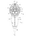
本実施形態における充電用コネクタ10は、外部電源側から延びる多芯ケーブル40の端末に接続され、車両に取り付けられた図示しない車両側コネクタに嵌合可能とされている。<Embodiment>
An embodiment of the present invention will be described with reference to FIGS.
The
充電用コネクタ10は、図1及び図2に示すように、車両側コネクタに設けられた図示しない車両側フード部内に嵌合可能な合成樹脂製の前側ハウジング20と、この前側ハウジング20の後部に組み付けられる合成樹脂製の後側ハウジング(本発明の「ハウジング」の一例)21とを備えて構成されている。 As shown in FIGS. 1 and 2, the
前側ハウジング20は略円筒状に形成されており、前側ハウジング20の内部には、複数の雄型端子22が保持された端子保持部23が設けられている。雄型端子22は、車両側フード部内に前側ハウジング20が正規に嵌合されると、車両側フード部内に設けられた図示しない雌型端子と導通可能に接続されるようになっている。 The
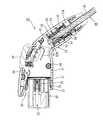
後側ハウジング21は、左右方向中央部で二つに分割される一対の半割体21Aからなり、一対の半割体21を左右両側から組み合わせ、ねじ固定することで構成されている。また、後側ハウジング21は、前側ハウジング20の後部から後方に延びたハウジング本体部24と、ハウジング本体部24の後端部から斜め下に向かって延びるグリップ部25とを備えており、ハウジング本体部24とグリップ部25とは一体に形成されている。 The
ハウジング本体部24の前端部における内周面には、全周に亘って装着溝26が形成されている。一方、前側ハウジング20の後部における外周面には、ハウジング本体部24の装着溝26に嵌合可能なフランジ27が全周に亘って形成されている。前側ハウジング20の後部をハウジング本体部24によって左右両側から挟み込み、フランジ27がハウジング本体部24の装着溝26に適合して嵌合することで、図2に示すように、前側ハウジング20の後方に後側ハウジング21が組み付けられている。 A
ハウジング本体部24の内部における上側には、前後方向に延びる嵌合レバー28が装着されている。嵌合レバー28は、前後方向略中央部を中心に揺動可能にハウジング本体部24に保持されており、嵌合レバー28の前端部は、前側ハウジング20の上方に配され、嵌合レバー28の後端部は、ハウジング本体部24の後部上面から上方に突出している。 A
嵌合レバー28の前端部における下側には、係止突起29が突設されており、車両側フード部と前側ハウジング20とが正規に嵌合されると、係止突起29が車両側フード部に係止することにより、車両側フード部と前側ハウジング20とが嵌合状態に保持されるようになっている。 A
嵌合レバー28の後端部におけるハウジング本体部24から上方突出した部分は、解除部30とされている。解除部30を下方に押圧することで、嵌合レバー28の前端部が上方に持ち上がり、係止突起29と車両側フード部との係止状態が解除されることで、車両側フード部から前側ハウジング20を離脱させることができるようになっている。 A portion of the rear end portion of the
ハウジング本体部24の下側には、複数の水抜き孔31が形成されている。これらの水抜き孔31は、充電用コネクタ10が雨などに晒されて後側ハウジング21の半割体21A間やハウジング本体部24と嵌合レバー28との間の隙間などから水が浸入した場合でも、外部に水を逃がすことができるようになっている。 A plurality of
グリップ部25は、ハウジング本体部24よりも細い形状に形成されており、グリップ部25の内部には、グリップ部25の斜め下後方から多芯ケーブル40が引き込まれている。グリップ部25に引き込まれた多芯ケーブル40の外周面には、金属製の電線保持部32が嵌着されており、この電線保持部32がグリップ部25の内部に収容されることで、グリップ部25に多芯ケーブル40が保持固定されている。なお、以下より、グリップ部25の内部構造においては多芯ケーブル40の延びる方向を前後方向として、グリップ部25から多芯ケーブル40が引き出された方向を後方として説明する。 The
多芯ケーブル40は、図示しない外部電源側から延びる電源線や信号線などの複数(本実施形態では4本)の電線41が一括して束ねられて合成樹脂製の外被覆42によって覆われることで一本にまとめられている。また、多芯ケーブル40の端末では、図2及び図3に示すように、外被覆42が皮剥ぎされることで4本の電線41が露出した状態でばらされ、それぞれの電線41が前側ハウジング20の雄型端子22などの所定の接続部に接続されている(図示省略)。 In the
さて、多芯ケーブル40の外被覆42の端末には、図2及び図3に示すように、シール部材50が装着されている。シール部材50は、多芯ケーブル40の外被覆42の端末に冠着されるゴム栓51と、このゴム栓51を内部に収容する合成樹脂製のキャップ(本発明の「規制部材」の一例)52とから構成されている。 Now, as shown in FIGS. 2 and 3, a
ゴム栓51は、弾性材からなり、図4乃至図7に示すように、前後方向に延びる略円筒状のケーブルシール部53と、ケーブルシール部53の前端部に形成された電線シール部54とを備えて構成されている。 The
ケーブルシール部53は、その内部に多芯ケーブル40の外被覆42が適合して嵌り込むように形成されている。ケーブルシール部53の内周面には、外被覆42の外周面に全周に亘って弾性的に密着する複数条(本実施形態では3条)の外被覆側リップ55が全周に亘って周設されている。外被覆側リップ55は、ケーブルシール部53の後部に配されており、ケーブルシール部53内に多芯ケーブル40の外被覆42が嵌り込んだ際に、外被覆42の外周面に全周に亘って密着する。これにより、外被覆42とケーブルシール部53の内周面との間からケーブルシール部53内に水などが浸入することを防止することができるようになっている。
ケーブルシール部53の外周面には、キャップ側リップ56が全周にわたって周設されている。キャップ側リップ56は、ケーブルシール部53の前部と後部の二箇所に2条ずつに分かれて配されており、ケーブルシール部53の後部におけるキャップ側リップ56は、外被覆側リップ55の外側に配されている。The
A cap-
電線シール部54は、図3に示すように、電線41が延びる方向である前後方向と直交した配置で、ケーブルシール部53の前端開口を塞ぐようにケーブルシール部53と一体に形成されている。また、電線シール部54は、ケーブルシール部の前部におけるキャップ側リップ56の内側に配されている。
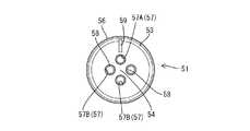
電線シール部54には、外被覆42の端末から露出された電線41を個別に挿通させる電線挿通孔57が形成されている。また、電線挿通孔57は、多芯ケーブル40の外被覆42から露出した電線41の本数に対応して複数(本実施形態では4つ)形成されている。As shown in FIG. 3, the
The
電線挿通孔57は、電線シール部54を前後方向に貫通して形成されており、電線挿通孔57の内周面には、電線41の外周面に弾性的に密着する電線側リップ58が全周に亘って周設されている。電線側リップ58は、電線挿通孔57内に電線41が挿通されると、電線41の外周面に全周に亘って密着するようになっている。これにより、電線41と電線シール部54との間からケーブルシール部53内に水などが浸入することを防止することができる。 The electric
すなわち、多芯ケーブル40における外被覆42の端末全体をケーブルシール部53と電線シール部54とで覆うことができるようになっており、ケーブルシール部53の外被覆側リップ55を外被覆42の外周面に弾性的に密着させると共に、電線シール部54の電線側リップ58を電線41の外周面に弾性的に密着させることで、多芯ケーブル40における外被覆42の端末を止水することができるようになっている。 That is, the entire terminal of the
また、4つの電線挿通孔57のうち、1つの電線挿通孔57Aの孔径が他の3つの電線挿通孔57Bの孔径に比べて僅かに小さく形成されている。また、ケーブルシール部53において、孔径が小さい電装通孔57Aの径方向外側の位置には、径方向外側に向かって直線的に延びる目印59が形成されている。
目印59は、ケーブルシール部53の前端面及び後端面の二箇所に凹んだ形態で形成されている。Of the four electric wire insertion holes 57, the diameter of one electric
The
一方、多芯ケーブル40の外被覆42から露出された4本の電線41のうち、1本の電線41の外径が他の3本の電線41の外径に比べて僅かに小さく形成されており、外径の小さい電線41は、孔径の小さい電線挿通孔57Aに適合して挿通されるようになっている。つまり、目印59を確認することで、外径の小さい電線41を挿通させる孔径の小さい電線挿通孔57Aを見分けることができ、外径の小さい電線41を孔径の小さい電線挿通孔57Aに容易に挿通させることができる。これにより、電線挿通孔57に電線41を挿通させる作業性を向上させることができると共に、目印59を確認することで、外径の小さい電線41を他の電線41が挿通される電線挿通孔57Bに間違って挿通させることを抑制することができる。 On the other hand, of the four
一方、キャップ52は、前後方向に延びる円筒状に形成されており、前後方向に貫通した形態をなしている。また、キャップ52は、その内部にゴム栓51のケーブルシール部53が適合して収容されるように形成されている。キャップ52の前端縁には、キャップ52の軸心に向かって張り出す前止まり部52Aが周設されており、キャップ52の内部に後方からケーブルシール部53が挿入されると、ケーブルシール部53の前端面がキャップ52の前止まり部52Aに当接することで、キャップ52に対してケーブルシール部53が前止まりされるようになっている。これにより、キャップ52に対してゴム栓51を正規の位置に容易に装着することができるようになっている。 On the other hand, the
また、キャップ52に対してゴム栓51が正規の位置に装着されると、ケーブルシール部53がキャップ52内に完全に収容され、ケーブルシール部53のキャップ側リップ56がキャップ52の内周面に密着するようになっている。そして、キャップ52内に収容された状態のケーブルシール部53に多芯ケーブル40を組み付けると、図3に示すように、電線挿通孔57内に電線41が挿通されて、外側に膨張しようとする電線シール部54及びケーブルシール部53の前部がキャップ52によって膨張することを規制される。
また、ケーブルシール部53の後部においても、ケーブルシール部53の前部と同様に、ケーブルシール部53内に外被覆42が収容されて、外側に膨張しようとするケーブルシール部53の後部がキャップ52によって膨張することを規制される。これにより、電線41と電線シール部54との間からケーブルシール部53内に水などが浸入することを確実に防止することができると共に、外被覆42とケーブルシール部53との間からケーブルシール部53内に水などが浸入することを確実に防止することができる。When the
Further, in the rear part of the
本実施形態は以上のような構成であって、充電用コネクタ10における多芯ケーブル40にシール部材50を組み付ける手順を簡単に説明すると共に、その作用・効果を説明する。
まず、多芯ケーブル40の端末において、外被覆42を皮剥して、4本の電線41をばらした状態にする。The present embodiment is configured as described above. The procedure for assembling the
First, at the end of the
次に、キャップ52の内部にゴム栓51を挿入し、ゴム栓51におけるケーブルシール部53の内部に電線41を後方から挿入して、各電線41を対応する電線挿通孔57に挿通させる。このとき、4つの電線挿通孔57のうち、1つの電線挿通孔57Aの孔径が他の3つの孔径に比べて小さく形成されているため、いずれの電線挿通孔57の孔径が小さいかを確認する必要がある。ところが、本実施形態によると、他の3つに比べて孔径が小さい電線挿通孔57Aの近傍には目印59が形成されていることから、各電線挿通孔57の孔径の大きさを確認することなく、各電線41を対応した電線挿通孔57に挿通させることができる。これにより、電線41を挿通させる作業性を向上させることができる。
また、全ての電線41が対応する電線挿通孔57に挿通されると、電線41の外周面に電線シール部54の電線側リップ58が全周に亘って弾性的に密着すると共に、ケーブルシール部53の前部におけるキャップ側リップ56がキャップ52の内周面に全周に亘って弾性的に密着し、電線シール部54と電線41との間の隙間が確実にシールされる。Next, the
When all the
電線41を電線挿通孔57に挿通させたところで、ケーブルシール部53の内部に多芯ケーブル40の外被覆42の端末を後方から挿入し、外被覆42の外周面にケーブルシール部53の外被覆側リップ55が全周に亘って弾性的に密着すると共に、キャップ52の内周面にケーブルシール部53の後部におけるキャップ側リップ56が全周に亘って弾性的に密着することで、ケーブルシール部53と外被覆42との間の隙間が確実にシールされる。 When the
すなわち、キャップ52内にゴム栓51を組み付けて、各電線41を電線挿通孔57に挿通させると共に、外被覆42をケーブルシール部53に挿入するだけで、各電線41間の隙間を電線シール部54によって塞ぐと共に、外被覆42とケーブルシール部53との間をシールすることができる。これにより、多芯ケーブル40における外被覆42の端末を止水することができる。 That is, the
以上のように、本実施形態によると、ゴム栓51や合成樹脂製のキャップ52などの安価なシール部材50によって、多芯ケーブル40における外被覆42の端末を止水することができる。これにより、熱収縮チューブやシール剤などの高価なシール部材を用いる場合に比べて、製造コストを低減させることができる。 As described above, according to the present embodiment, the terminal of the
また、本実施形態によると、キャップ52内にゴム栓51を挿入し、各電線41を電線挿通孔57に挿通させて、外被覆42をケーブルシール部53に挿入するだけで、外被覆42の端末を止水することができるので、多芯ケーブル40に対するシール部材50の組み付け作業が非常に容易である。これにより、外被覆42の端末における各電線41間にシール剤を充填して、外被覆42の端末に熱収縮チューブなどを被せて加熱処理する場合に比べて、止水作業の効率を向上させることができる。 In addition, according to the present embodiment, the
さらに、本実施形態によると、外被覆42や電線41に対してゴム栓51を弾性的に密着させてシールしていることから、各電線41間にシール剤を充填して各電線を前後方向に長く接着し、外被覆42の外面を熱収縮チューブによってシールする場合に比べて、外被覆42や電線41にシール部材50が密着する部分を小さくすることができる。これにより、止水構造を小さくすることができ、充電用コネクタ10の小型化を図ることができる。 Furthermore, according to the present embodiment, since the
<他の実施形態>
本発明は上記記述及び図面によって説明した実施形態に限定されるものではなく、例えば次のような実施形態も本発明の技術的範囲に含まれる。
(1)上記実施形態では、4つの電線挿通孔57のうち、1つの電線挿通孔57Aの孔径が他の3つの孔径に比べて小さく形成された構成としたが、本発明はこのような態様に限定されるものではなく、例えば、4つの電線挿通孔の孔径が全て同じに構成されていてもよく、2つの電線挿通孔の孔径が小さく形成されていてもよい。
(2)上記実施形態では、目印59の形状を直線的に延びた形態に構成したが、本発明はこのような態様に限定されるものではなく、例えば、目印の形状が円形や矢印などによって構成されていてもよい。
(3)上記実施形態では、合成樹脂製のキャップ52を用いた構成としたが、本発明はこのような態様に限定されるものではなく、例えば、金属製のキャップを用いてもよい。
(4)上記実施形態では、電線挿通孔57が4つ形成された電線シール部54を構成したが、本発明はこのような態様に限定されるものではなく、例えば、電線シール部に電線挿通孔が5つや6つ形成されていてもよい。<Other embodiments>
The present invention is not limited to the embodiments described with reference to the above description and drawings. For example, the following embodiments are also included in the technical scope of the present invention.
(1) Although the hole diameter of one
(2) In the above embodiment, the shape of the
(3) In the said embodiment, although it was set as the structure using the
(4) In the above embodiment, the electric
10:充電用コネクタ
21:後側ハウジング(ハウジング)
40:多芯ケーブル
41:電線
42:外被覆
50:シール部材
51:ゴム栓
52:キャップ(規制部材)
53:ケーブルシール部
54:電線シール部
57:電線挿通孔
59:目印10: Charging connector 21: Rear housing (housing)
40: Multi-core cable 41: Electric wire 42: Outer sheath 50: Seal member 51: Rubber plug 52: Cap (regulating member)
53: Cable seal part 54: Electric wire seal part 57: Electric wire insertion hole 59: Mark
Claims (3)
Translated fromJapanese弾性材からなるゴム栓と、
前記ゴム栓に外嵌することで、前記ゴム栓が膨張することを規制する規制部材とを備えており、
前記ゴム栓には、前記外被覆の外周面に全周に亘って弾性的に密着するケーブルシール部が形成されており、
前記ケーブルシール部は、同ケーブルシール部における前記複数の電線が引き出される前側の前端部に一体に設けられ、前記複数の電線の外周面に全周に亘って個別にかつ弾性的に密着する電線シール部を有していることを特徴とするシール部材。A sealing member that is attached to the end of a multi-core cable that bundles a plurality of electric wires in a lump and is covered with an outer covering, and is accommodated in a housing that constitutes a charging connector,
A rubber stopper made of an elastic material;
A regulation member that regulates expansion of the rubber plug by being externally fitted to the rubber plug;
The rubber plug is formed with a cable seal portion that elastically adheres to the outer peripheral surface of the outer coating over the entire circumference,
The cable seal portion is integrally provided at a front end portion on the front side from which the plurality of electric wires are drawn out in the cable seal portion, and individually and elastically adheres to the outer peripheral surface of the plurality of electric wires over the entire circumference. A seal member having a seal portion.
前記電線シール部は、前記電線が延びる方向と交差した配置で前記ケーブルシール部の前端開口を塞ぐように形成されており、
前記規制部材は、前記ケーブルシール部の外周面の全体を覆う円筒状に形成されていることを特徴とする請求項1記載のシール部材。The cable seal portion is formed in a cylindrical shape covering the outer coating terminal over the entire circumference,
The wire seal portion is formed so as to close the front end opening of the cable seal portion in an arrangement intersecting the direction in which the wire extends.
The sealing member according to claim 1, wherein the regulating member is formed in a cylindrical shape covering the entire outer peripheral surface of the cable seal portion.
前記ケーブルシール部には、前記複数の電線挿通孔のうち特定の電線挿通孔を示す目印が付されていることを特徴とする請求項1または請求項2記載のシール部材。The wire seal part is formed with a plurality of wire insertion holes for individually inserting the plurality of wires.
The seal member according to claim 1 or 2, wherein a mark indicating a specific electric wire insertion hole among the plurality of electric wire insertion holes is attached to the cable seal portion.
Priority Applications (4)
| Application Number | Priority Date | Filing Date | Title |
|---|---|---|---|
| JP2011237248AJP5757219B2 (en) | 2011-10-28 | 2011-10-28 | Seal member |
| EP12006128.8AEP2587594A1 (en) | 2011-10-28 | 2012-08-29 | Seal member, charging connector provided thereof, and mounting method for a seal member |
| US13/609,334US8727799B2 (en) | 2011-10-28 | 2012-09-11 | Seal member and a charging connector provided therewith |
| CN2012104177482ACN103094874A (en) | 2011-10-28 | 2012-10-26 | Seal member, and mounting method for a seal member, and charging connector provided thereof |
Applications Claiming Priority (1)
| Application Number | Priority Date | Filing Date | Title |
|---|---|---|---|
| JP2011237248AJP5757219B2 (en) | 2011-10-28 | 2011-10-28 | Seal member |
Publications (2)
| Publication Number | Publication Date |
|---|---|
| JP2013097898Atrue JP2013097898A (en) | 2013-05-20 |
| JP5757219B2 JP5757219B2 (en) | 2015-07-29 |
Family
ID=47216001
Family Applications (1)
| Application Number | Title | Priority Date | Filing Date |
|---|---|---|---|
| JP2011237248AExpired - Fee RelatedJP5757219B2 (en) | 2011-10-28 | 2011-10-28 | Seal member |
Country Status (4)
| Country | Link |
|---|---|
| US (1) | US8727799B2 (en) |
| EP (1) | EP2587594A1 (en) |
| JP (1) | JP5757219B2 (en) |
| CN (1) | CN103094874A (en) |
Cited By (16)
| Publication number | Priority date | Publication date | Assignee | Title |
|---|---|---|---|---|
| WO2014065120A1 (en)* | 2012-10-25 | 2014-05-01 | 矢崎総業株式会社 | Charging connector |
| JP2015090818A (en)* | 2013-11-06 | 2015-05-11 | 住友電装株式会社 | Wire harness |
| JP2015204205A (en)* | 2014-04-14 | 2015-11-16 | パナソニックIpマネジメント株式会社 | charging connector |
| WO2015199055A1 (en)* | 2014-06-26 | 2015-12-30 | 株式会社オートネットワーク技術研究所 | Seal member, and seal structure for multicore cable |
| WO2015199056A1 (en)* | 2014-06-26 | 2015-12-30 | 株式会社オートネットワーク技術研究所 | Sealing member |
| JP2016077143A (en)* | 2015-11-13 | 2016-05-12 | 株式会社オートネットワーク技術研究所 | Seal member, and seal structure for multicore cable |
| WO2016104241A1 (en)* | 2014-12-25 | 2016-06-30 | 株式会社オートネットワーク技術研究所 | Seal structure for multi-core cable |
| JP2016162584A (en)* | 2015-03-02 | 2016-09-05 | 株式会社オートネットワーク技術研究所 | Multi-core cable seal structure |
| JPWO2015198506A1 (en)* | 2014-06-26 | 2017-04-20 | 株式会社オートネットワーク技術研究所 | Multi-core cable seal structure |
| WO2017082376A1 (en)* | 2015-11-12 | 2017-05-18 | 株式会社オートネットワーク技術研究所 | Sealing structure for cable, and sealing member |
| JP2017112756A (en)* | 2015-12-17 | 2017-06-22 | 株式会社オートネットワーク技術研究所 | Multi-core cable seal structure |
| WO2017110423A1 (en)* | 2015-12-22 | 2017-06-29 | 株式会社オートネットワーク技術研究所 | Cable holding structure |
| WO2017110377A1 (en)* | 2015-12-24 | 2017-06-29 | 株式会社オートネットワーク技術研究所 | Seal structure for multicore cable, and rubber plug |
| JP2020030907A (en)* | 2018-08-21 | 2020-02-27 | 株式会社オートネットワーク技術研究所 | Electric wire cover and connector with electric wire cover |
| US11296453B2 (en) | 2017-03-14 | 2022-04-05 | Autonetworks Technologies, Ltd. | Waterproof structure of connector |
| CN114899682A (en)* | 2022-03-28 | 2022-08-12 | 潍坊路加精工有限公司 | Automatic assembling equipment for multi-core wire |
Families Citing this family (16)
| Publication number | Priority date | Publication date | Assignee | Title |
|---|---|---|---|---|
| US9537252B2 (en)* | 2013-03-19 | 2017-01-03 | Sumitomo Wiring Systems, Ltd. | Vehicle-side connector |
| DE102014112045B4 (en)* | 2014-08-22 | 2018-02-01 | Amphenol-Tuchel Electronics Gmbh | Connector and connector housing with a sealing element |
| JP6455361B2 (en)* | 2015-08-20 | 2019-01-23 | 株式会社オートネットワーク技術研究所 | Communication connector and communication connector with wires |
| US10118496B2 (en)* | 2016-02-04 | 2018-11-06 | Dragon Bite Industrial Co., Ltd. | Waterproofing members integrally formed with elements of a charging coupler |
| JP6809427B2 (en)* | 2017-09-28 | 2021-01-06 | 豊田合成株式会社 | Steering wheel |
| JP6924387B2 (en)* | 2018-03-15 | 2021-08-25 | 株式会社オートネットワーク技術研究所 | Wire holding structure |
| JP2019169244A (en)* | 2018-03-22 | 2019-10-03 | 住友電装株式会社 | Waterproof connector |
| CN108598774B (en)* | 2018-05-31 | 2020-02-28 | 杨贵珍 | A charging gun that can be forcibly powered off |
| JP2019220251A (en)* | 2018-06-15 | 2019-12-26 | 住友電装株式会社 | Waterproof structure for multicore wire |
| JP2019220248A (en)* | 2018-06-15 | 2019-12-26 | 住友電装株式会社 | Waterproof structure for multicore wire |
| CN109238566B (en)* | 2018-10-30 | 2023-09-15 | 歌尔科技有限公司 | Waterproof mounting structure of charging needle, waterproof detection method of charging needle and wrist-wearing equipment |
| USD1030676S1 (en)* | 2022-01-26 | 2024-06-11 | Chogori Technology Co., Ltd | Waterproof connector |
| USD1018469S1 (en)* | 2022-05-17 | 2024-03-19 | Christopher Eckhard Maiwald | Charging adapter |
| USD1040110S1 (en)* | 2023-06-01 | 2024-08-27 | Shenzhen Yongchuangcheng Technology Co., Ltd. | Charging connector |
| USD1040089S1 (en)* | 2023-09-12 | 2024-08-27 | Shenzhen Yongchuangcheng Technology Co., Ltd. | Charging connector |
| USD1046773S1 (en)* | 2023-09-12 | 2024-10-15 | Shenzhen Yongchuangcheng Technology Co., Ltd. | Charging adapter |
Citations (3)
| Publication number | Priority date | Publication date | Assignee | Title |
|---|---|---|---|---|
| JPS6071075U (en)* | 1983-10-21 | 1985-05-20 | 大阪ヒユーズ株式会社 | Multi-branched cladding tube |
| JP2001143810A (en)* | 1999-11-16 | 2001-05-25 | Yazaki Corp | Connector waterproof structure |
| JP2011028853A (en)* | 2009-07-21 | 2011-02-10 | Sumitomo Wiring Syst Ltd | Molded connector |
Family Cites Families (17)
| Publication number | Priority date | Publication date | Assignee | Title |
|---|---|---|---|---|
| GB468410A (en)* | 1935-12-31 | 1937-06-30 | Fritz Siegfried Loebl | Improvements in or relating to a device for sealing electric cable ends |
| CA963548A (en)* | 1972-02-25 | 1975-02-25 | David M. Howie | End seals for electric cables |
| GB8901670D0 (en)* | 1989-01-26 | 1989-03-15 | Bicc Plc | Termination of mineral insulated electric cable |
| JPH0822862A (en)* | 1994-07-07 | 1996-01-23 | Yazaki Corp | Waterproof rubber stopper |
| US5767448A (en)* | 1996-09-30 | 1998-06-16 | Raychem Corporation | Sealing device |
| US6341983B1 (en)* | 2000-04-05 | 2002-01-29 | Delphi Technologies, Inc. | Co-molded seal and strain relief for automotive electrical connections |
| JP2001345143A (en) | 2000-05-31 | 2001-12-14 | Yazaki Corp | Fixing structure of waterproof plug |
| DE10054714B4 (en)* | 2000-11-04 | 2005-09-15 | Siegfried Rebhan | Method for sealing a cable or cable set on / in a cable feedthrough element and a cable feedthrough element |
| JP2002324621A (en) | 2001-04-24 | 2002-11-08 | Yazaki Corp | connector |
| JP3804483B2 (en)* | 2001-05-18 | 2006-08-02 | 住友電装株式会社 | Waterproof connector |
| JP4214898B2 (en)* | 2003-11-27 | 2009-01-28 | 住友電装株式会社 | Waterproof connector |
| JP4259453B2 (en)* | 2004-10-29 | 2009-04-30 | 住友電装株式会社 | Waterproof connector |
| ITMI20050121U1 (en)* | 2005-04-08 | 2006-10-09 | Guzzini Illuminazione S P A I | SEALING ELEMENT FOR TERMINAL PORTIONS OF MULTIPOLAR CABLES |
| SG127773A1 (en)* | 2005-06-01 | 2006-12-29 | Mea Technologies Pte Ltd | Waterproof connector |
| JP4678288B2 (en)* | 2005-11-24 | 2011-04-27 | 住友電装株式会社 | Rubber stopper and waterproof connector |
| EP2005530B1 (en)* | 2006-03-22 | 2012-09-19 | FCI Automotive Holding | Sealed electrical connector |
| JP2010073664A (en)* | 2008-09-22 | 2010-04-02 | Sumitomo Wiring Syst Ltd | Waterproof connector and rubber stopper |
- 2011
- 2011-10-28JPJP2011237248Apatent/JP5757219B2/ennot_activeExpired - Fee Related
- 2012
- 2012-08-29EPEP12006128.8Apatent/EP2587594A1/ennot_activeWithdrawn
- 2012-09-11USUS13/609,334patent/US8727799B2/ennot_activeExpired - Fee Related
- 2012-10-26CNCN2012104177482Apatent/CN103094874A/enactivePending
Patent Citations (3)
| Publication number | Priority date | Publication date | Assignee | Title |
|---|---|---|---|---|
| JPS6071075U (en)* | 1983-10-21 | 1985-05-20 | 大阪ヒユーズ株式会社 | Multi-branched cladding tube |
| JP2001143810A (en)* | 1999-11-16 | 2001-05-25 | Yazaki Corp | Connector waterproof structure |
| JP2011028853A (en)* | 2009-07-21 | 2011-02-10 | Sumitomo Wiring Syst Ltd | Molded connector |
Cited By (29)
| Publication number | Priority date | Publication date | Assignee | Title |
|---|---|---|---|---|
| WO2014065120A1 (en)* | 2012-10-25 | 2014-05-01 | 矢崎総業株式会社 | Charging connector |
| JP2015090818A (en)* | 2013-11-06 | 2015-05-11 | 住友電装株式会社 | Wire harness |
| WO2015068581A1 (en)* | 2013-11-06 | 2015-05-14 | 住友電装株式会社 | Wire harness |
| JP2015204205A (en)* | 2014-04-14 | 2015-11-16 | パナソニックIpマネジメント株式会社 | charging connector |
| US9905337B2 (en) | 2014-06-26 | 2018-02-27 | Autonetowkrs Technologies, Ltd. | Sealing structure of multicore cable |
| JPWO2015198506A1 (en)* | 2014-06-26 | 2017-04-20 | 株式会社オートネットワーク技術研究所 | Multi-core cable seal structure |
| JP2016010304A (en)* | 2014-06-26 | 2016-01-18 | 株式会社オートネットワーク技術研究所 | Seal member |
| JP2016010303A (en)* | 2014-06-26 | 2016-01-18 | 株式会社オートネットワーク技術研究所 | Seal member and seal structure of multi-core cable |
| US9842671B2 (en) | 2014-06-26 | 2017-12-12 | Autonetworks Technologies, Ltd. | Seal member and seal structure for multicore cable |
| WO2015199055A1 (en)* | 2014-06-26 | 2015-12-30 | 株式会社オートネットワーク技術研究所 | Seal member, and seal structure for multicore cable |
| US10236671B2 (en) | 2014-06-26 | 2019-03-19 | Autonetworks Technologies, Ltd. | Sealing member |
| WO2015199056A1 (en)* | 2014-06-26 | 2015-12-30 | 株式会社オートネットワーク技術研究所 | Sealing member |
| WO2016104241A1 (en)* | 2014-12-25 | 2016-06-30 | 株式会社オートネットワーク技術研究所 | Seal structure for multi-core cable |
| WO2016140173A1 (en)* | 2015-03-02 | 2016-09-09 | 株式会社オートネットワーク技術研究所 | Seal structure for multi-core cable |
| JP2016162584A (en)* | 2015-03-02 | 2016-09-05 | 株式会社オートネットワーク技術研究所 | Multi-core cable seal structure |
| US10003141B2 (en) | 2015-03-02 | 2018-06-19 | Autonetworks Technologies, Ltd. | Seal structure for multi-core cable |
| WO2017082376A1 (en)* | 2015-11-12 | 2017-05-18 | 株式会社オートネットワーク技術研究所 | Sealing structure for cable, and sealing member |
| JP2017093185A (en)* | 2015-11-12 | 2017-05-25 | 株式会社オートネットワーク技術研究所 | Seal structure of cable and seal member |
| JP2016077143A (en)* | 2015-11-13 | 2016-05-12 | 株式会社オートネットワーク技術研究所 | Seal member, and seal structure for multicore cable |
| JP2017112756A (en)* | 2015-12-17 | 2017-06-22 | 株式会社オートネットワーク技術研究所 | Multi-core cable seal structure |
| WO2017104392A1 (en)* | 2015-12-17 | 2017-06-22 | 株式会社オートネットワーク技術研究所 | Multi-core cable seal structure |
| WO2017110423A1 (en)* | 2015-12-22 | 2017-06-29 | 株式会社オートネットワーク技術研究所 | Cable holding structure |
| JP2017118624A (en)* | 2015-12-22 | 2017-06-29 | 株式会社オートネットワーク技術研究所 | Holding structure of cable |
| WO2017110377A1 (en)* | 2015-12-24 | 2017-06-29 | 株式会社オートネットワーク技術研究所 | Seal structure for multicore cable, and rubber plug |
| JPWO2017110377A1 (en)* | 2015-12-24 | 2018-06-28 | 株式会社オートネットワーク技術研究所 | Multi-core cable seal structure and rubber plug |
| US11296453B2 (en) | 2017-03-14 | 2022-04-05 | Autonetworks Technologies, Ltd. | Waterproof structure of connector |
| JP2020030907A (en)* | 2018-08-21 | 2020-02-27 | 株式会社オートネットワーク技術研究所 | Electric wire cover and connector with electric wire cover |
| WO2020039877A1 (en)* | 2018-08-21 | 2020-02-27 | 株式会社オートネットワーク技術研究所 | Electric wire cover and electric wire cover-equipped connector |
| CN114899682A (en)* | 2022-03-28 | 2022-08-12 | 潍坊路加精工有限公司 | Automatic assembling equipment for multi-core wire |
Also Published As
| Publication number | Publication date |
|---|---|
| US8727799B2 (en) | 2014-05-20 |
| JP5757219B2 (en) | 2015-07-29 |
| US20130105219A1 (en) | 2013-05-02 |
| EP2587594A1 (en) | 2013-05-01 |
| CN103094874A (en) | 2013-05-08 |
Similar Documents
| Publication | Publication Date | Title |
|---|---|---|
| JP5757219B2 (en) | Seal member | |
| JP6065228B2 (en) | connector | |
| CN105359348B (en) | Connector | |
| US20130316572A1 (en) | Connector assembly | |
| CN107801423A (en) | Sealing structure of multi-core cable | |
| EP3691046B1 (en) | Connector and wire harness | |
| JP2012089640A (en) | Hermetic structure for cable insertion part, and closure having the same | |
| WO2015098488A1 (en) | Connector | |
| CN105281157B (en) | Electrical cord assembly | |
| CN105379026B (en) | Connector | |
| JP5769024B2 (en) | Wire fixing member | |
| JP5170013B2 (en) | Shield connector | |
| WO2023008027A1 (en) | Charging connector | |
| JP6722412B2 (en) | Terminal cover and connector | |
| JP6605360B2 (en) | connector | |
| JP2015018616A (en) | Connector, and connector unit | |
| JP5562157B2 (en) | Relay connector | |
| JP6194848B2 (en) | connector | |
| JP2019220248A (en) | Waterproof structure for multicore wire | |
| JP4278556B2 (en) | Connector mating structure | |
| JP2015185282A (en) | Waterproof structure of connector | |
| JP6169385B2 (en) | Charging connector | |
| JP6564251B2 (en) | Terminal cover | |
| JP2018010771A (en) | Connector protection structure and wiring harness | |
| JP2005310585A (en) | Connector for equipment |
Legal Events
| Date | Code | Title | Description |
|---|---|---|---|
| A621 | Written request for application examination | Free format text:JAPANESE INTERMEDIATE CODE: A621 Effective date:20140331 | |
| A977 | Report on retrieval | Free format text:JAPANESE INTERMEDIATE CODE: A971007 Effective date:20150109 | |
| A131 | Notification of reasons for refusal | Free format text:JAPANESE INTERMEDIATE CODE: A131 Effective date:20150115 | |
| A521 | Written amendment | Free format text:JAPANESE INTERMEDIATE CODE: A523 Effective date:20150302 | |
| A131 | Notification of reasons for refusal | Free format text:JAPANESE INTERMEDIATE CODE: A131 Effective date:20150324 | |
| A521 | Written amendment | Free format text:JAPANESE INTERMEDIATE CODE: A523 Effective date:20150409 | |
| TRDD | Decision of grant or rejection written | ||
| A01 | Written decision to grant a patent or to grant a registration (utility model) | Free format text:JAPANESE INTERMEDIATE CODE: A01 Effective date:20150507 | |
| A61 | First payment of annual fees (during grant procedure) | Free format text:JAPANESE INTERMEDIATE CODE: A61 Effective date:20150520 | |
| R150 | Certificate of patent or registration of utility model | Ref document number:5757219 Country of ref document:JP Free format text:JAPANESE INTERMEDIATE CODE: R150 | |
| LAPS | Cancellation because of no payment of annual fees |