JP2013097676A - Arrival time estimation device, arrival time estimation method, arrival time estimation program and information presentation device - Google Patents
Arrival time estimation device, arrival time estimation method, arrival time estimation program and information presentation deviceDownload PDFInfo
- Publication number
- JP2013097676A JP2013097676AJP2011241466AJP2011241466AJP2013097676AJP 2013097676 AJP2013097676 AJP 2013097676AJP 2011241466 AJP2011241466 AJP 2011241466AJP 2011241466 AJP2011241466 AJP 2011241466AJP 2013097676 AJP2013097676 AJP 2013097676A
- Authority
- JP
- Japan
- Prior art keywords
- arrival time
- image signal
- calculated
- time estimation
- unit
- Prior art date
- Legal status (The legal status is an assumption and is not a legal conclusion. Google has not performed a legal analysis and makes no representation as to the accuracy of the status listed.)
- Pending
Links
Images


Classifications
- G—PHYSICS
- G06—COMPUTING OR CALCULATING; COUNTING
- G06V—IMAGE OR VIDEO RECOGNITION OR UNDERSTANDING
- G06V20/00—Scenes; Scene-specific elements
- G06V20/50—Context or environment of the image
- G06V20/56—Context or environment of the image exterior to a vehicle by using sensors mounted on the vehicle
- G06V20/58—Recognition of moving objects or obstacles, e.g. vehicles or pedestrians; Recognition of traffic objects, e.g. traffic signs, traffic lights or roads
Landscapes
- Engineering & Computer Science (AREA)
- Physics & Mathematics (AREA)
- General Physics & Mathematics (AREA)
- Multimedia (AREA)
- Theoretical Computer Science (AREA)
- Image Analysis (AREA)
- Traffic Control Systems (AREA)
- Image Processing (AREA)
Abstract
Description
Translated fromJapanese本発明は、到達時間推定装置、到達時間推定方法、到達時間推定プログラム、及び情報提示装置に関する。 The present invention relates to an arrival time estimation device, an arrival time estimation method, an arrival time estimation program, and an information presentation device.
路面上を走行する車両を安全に運転するために、車両の周囲の情報を運転者に提示する技術が提案されている。周囲の情報の一形態として、進行方向に位置する障害物を車載カメラが撮影した画像に基づいて検知する方法が提案されている。その中で、撮影した画像が表す被写体上の特徴点を複数個抽出し、抽出した特徴点間の距離変化を算出して被写体までの到達時間を推定する技術がある。
例えば、特許文献1に記載の衝突時間算出装置は、カメラにより撮像された画像上の同一対象物に属する任意の2点を評価点として抽出し、画像上に設定された任意の座標軸を基準として、抽出された2点の座標値の差分の絶対値の時間微分値を算出するとともに、2点の座標値の差分の絶対値と、時間微分値とに基づいて、抽出された2点を含む対象物がカメラの撮像面と衝突までに要する時間を算出する。In order to drive a vehicle traveling on a road surface safely, a technique for presenting information around the vehicle to the driver has been proposed. As one form of surrounding information, a method has been proposed in which an obstacle located in the traveling direction is detected based on an image taken by a vehicle-mounted camera. Among them, there is a technique for extracting a plurality of feature points on a subject represented by a photographed image and calculating a distance change between the extracted feature points to estimate an arrival time to the subject.
For example, the collision time calculation device described in
しかしながら、特許文献1の衝突時間算出装置によれば、抽出された2点が同一の対象物上にあり、カメラから等距離になければならない。また、対象物が小さい場合、2点以上の評価点が得られない場合があった。そのため、対象物までの到達時間を確実に推定することができなかった。 However, according to the collision time calculation apparatus of
本発明は上記の点に鑑みてなされたものであり、物体までの到達時間をより確実に推定することができる到達時間推定装置、到達時間推定方法、到達時間推定プログラム及び情報提示装置を提供する。 The present invention has been made in view of the above points, and provides an arrival time estimation device, an arrival time estimation method, an arrival time estimation program, and an information presentation device that can more reliably estimate the arrival time to an object. .
(1)本発明は上記の課題を解決するためになされたものであり、本発明の一態様は、画像信号をフレーム毎に入力する画像入力部と、前記画像入力部から入力された画像信号が表す物体を検知する物体検知部と、前記物体検知部が検知した物体までの方向を表す方向ベクトルに基づいて前記画像信号を撮影した撮影装置の光軸の回転を表す回転行列を算出し、過去の方向ベクトルに前記算出した回転行列を乗じたベクトルと、現在の方向ベクトルとに基づいて前記物体までの距離の変化を算出し、算出した距離の変化に基づいて当該物体までの到達時間を算出する到達時間算出部と、を備えることを特徴とする到達時間推定装置である。(1) The present invention has been made to solve the above problems, and one aspect of the present invention is an image input unit that inputs an image signal for each frame, and an image signal that is input from the image input unit. Calculating a rotation matrix representing rotation of the optical axis of the imaging device that captured the image signal based on a direction vector representing a direction to the object detected by the object detection unit; A change in distance to the object is calculated based on a vector obtained by multiplying a past direction vector by the calculated rotation matrix and a current direction vector, and an arrival time to the object is calculated based on the calculated change in distance. An arrival time estimation device comprising: an arrival time calculation unit for calculating.
(2)本発明のその他の態様は、上述の到達時間推定装置であって、前記画像入力部から入力された画像信号から前記物体検知部が検知した物体上の特徴点を抽出する特徴点抽出部を備え、前記到達時間算出部は、前記特徴点抽出部が抽出した特徴点の方向を、前記物体までの方向として前記到達時間を算出することを特徴とする。(2) Another aspect of the present invention is the arrival time estimation apparatus described above, wherein the feature point extraction extracts the feature point on the object detected by the object detection unit from the image signal input from the image input unit. And the arrival time calculation unit calculates the arrival time using the direction of the feature point extracted by the feature point extraction unit as the direction to the object.
(3)本発明のその他の態様は、画像信号をフレーム毎に入力する画像入力部と、前記画像入力部から入力された画像信号が表す物体を検知する物体検知部と、前記物体検知部が検知した物体までの方向を表す方向ベクトルに基づいて前記画像信号を撮影した撮影装置の光軸の回転を表す回転行列を算出し、過去の方向ベクトルに前記算出した回転行列を乗じたベクトルと、現在の方向ベクトルとに基づいて前記物体までの距離の変化を算出し、算出した距離の変化に基づいて当該物体までの到達時間を算出する到達時間算出部と前記到達時間算出部が算出した到達時間に基づいて、前記物体検知部が検知した物体に到達することを表す情報を出力するか否かを判断する出力判定部を備えることを特徴とする情報提示装置である。(3) According to another aspect of the present invention, an image input unit that inputs an image signal for each frame, an object detection unit that detects an object represented by the image signal input from the image input unit, and the object detection unit Based on a direction vector that represents the direction to the detected object, calculate a rotation matrix that represents the rotation of the optical axis of the imaging device that has captured the image signal, a vector obtained by multiplying the past direction vector by the calculated rotation matrix, and The arrival time calculation unit that calculates the change in the distance to the object based on the current direction vector and calculates the arrival time to the object based on the calculated change in the distance and the arrival time calculated by the arrival time calculation unit An information presentation apparatus comprising: an output determination unit that determines whether to output information indicating that the object detection unit has reached the object detected based on time.
(4)本発明のその他の態様は、到達時間推定装置における到達時間推定方法において、 前記到達時間推定装置が、画像信号をフレーム毎に入力する過程と、前記到達時間推定装置が、前記入力された画像信号が表す物体を検知する過程と、前記到達時間推定装置が、前記検知した物体までの方向を表す方向ベクトルに基づいて前記画像信号を撮影した撮影装置の光軸の回転を表す回転行列を算出し、過去の方向ベクトルに前記算出した回転行列を乗じたベクトルと、現在の方向ベクトルとに基づいて前記物体までの距離の変化を算出し、算出した距離の変化に基づいて当該物体までの到達時間を算出する過程と、を有することを特徴とする到達時間推定方法である。(4) According to another aspect of the present invention, in the arrival time estimation method in the arrival time estimation apparatus, the arrival time estimation apparatus inputs the image signal for each frame, and the arrival time estimation apparatus receives the input A process of detecting an object represented by the image signal, and a rotation matrix representing rotation of the optical axis of the imaging apparatus that captures the image signal based on a direction vector representing the direction to the detected object by the arrival time estimation device. And calculates a change in the distance to the object based on a vector obtained by multiplying the previous direction vector by the calculated rotation matrix and the current direction vector, and based on the calculated change in the distance to the object. And a process for calculating the arrival time of the arrival time.
(5)本発明のその他の態様は、到達時間推定装置のコンピュータに、画像信号をフレーム毎に入力する手順と、前記入力された画像信号が表す物体を検知する手順と、前記検知した物体までの方向を表す方向ベクトルに基づいて前記画像信号を撮影した撮影装置の光軸の回転を表す回転行列を算出し、過去の方向ベクトルに前記算出した回転行列を乗じたベクトルと、現在の方向ベクトルとに基づいて前記物体までの距離の変化を算出し、算出した距離の変化に基づいて当該物体までの到達時間を算出する手順と、を実行させるための到達時間推定プログラムである。(5) In another aspect of the present invention, a procedure for inputting an image signal for each frame to a computer of an arrival time estimation apparatus, a procedure for detecting an object represented by the input image signal, and the detected object A rotation matrix representing the rotation of the optical axis of the imaging apparatus that captured the image signal based on a direction vector representing the direction of the image signal, a vector obtained by multiplying the previous direction vector by the calculated rotation matrix, and a current direction vector And a procedure for calculating a change in the distance to the object on the basis of the distance and calculating an arrival time on the object based on the calculated change in the distance.
本発明によれば、物体までの到達時間をより確実に推定することができる。 According to the present invention, the arrival time to the object can be estimated more reliably.
(第1の実施形態)
以下、図面を参照しながら本発明の実施形態について説明する。
本実施形態に係る到達時間推定装置は、画像信号をフレーム毎に入力し、入力された画像信号が表す物体を検知する。また、当該到達時間推定装置は、検知した物体までの方向を表す方向ベクトルに基づいて前記画像信号を撮影した撮影装置の光軸の回転を表す回転行列を算出し、過去の方向ベクトルに前記算出した回転行列を乗じたベクトルと、現在の方向ベクトルとに基づいて前記物体までの距離の変化を算出し、算出した距離の変化に基づいて当該物体までの到達時間を算出する。また、本実施形態に係る情報提示装置は、当該到達時間推定装置の構成を備え、算出した到達時間に基づいて、検知した物体に到達することを表す情報を出力するか否かを判断する。(First embodiment)
Hereinafter, embodiments of the present invention will be described with reference to the drawings.
The arrival time estimation apparatus according to the present embodiment inputs an image signal for each frame and detects an object represented by the input image signal. In addition, the arrival time estimation device calculates a rotation matrix that represents rotation of the optical axis of the imaging device that captured the image signal based on a direction vector that represents the direction to the detected object, and the calculation is performed on the past direction vector. A change in distance to the object is calculated based on the vector multiplied by the rotation matrix and the current direction vector, and an arrival time to the object is calculated based on the calculated change in distance. Moreover, the information presentation apparatus according to the present embodiment includes the configuration of the arrival time estimation apparatus, and determines whether or not to output information indicating arrival at the detected object based on the calculated arrival time.
図1は、本実施形態に係る情報提示装置11の構成を示す概略図である。
情報提示装置11は、到達時間推定部12、警報判定部124及び警報出力部125を含んで構成される。
カメラ2は、周囲の画像を予め定められた時間間隔(例えば、1/30秒)で撮影し、撮影した画像信号を到達時間推定部12に出力する。フレームとは、1枚の画像を表す画像信号の単位である。1フレームの画像信号は、画素毎の輝度値を含んで構成される。カメラ2は、例えば、光軸の方向が情報提示装置11を搭載する自車両の正面前方になるように設置された車載用ビデオカメラである。これにより、カメラ2は、車両の正面前方の画像を撮影して画像信号を生成する。FIG. 1 is a schematic diagram illustrating a configuration of an
The
The
到達時間推定部12は、カメラ2から前述の時間間隔で画像信号をフレーム毎に入力される。到達時間推定部12は、入力された画像信号が表す物体を検知し、検知した物体に到達するまでの到達時間を算出する。到達時間推定部12が到達時間を算出する処理については後述する。到達時間推定部12は、算出した到達時間を表す到達時間情報を警報判定部124に出力する。到達時間推定部12の構成については、後述する。 The arrival
警報判定部124は、到達時間推定部12から入力された到達時間情報に基づいて前述の検知した物体に到達することを表す警報を出力するか否か判断する。警報判定部124は、例えば、入力された到達時間情報が予め設定された時間(例えば、30秒)よりも小さくなったとき、その警報を出力すると判断する。警報判定部124は、警報を出力すると判断したとき、警報を出力することを表す警報出力要求信号を生成し、生成した警報出力要求信号を警報出力部125に出力する。 The
警報出力部125は、警報判定部124から警報を出力することを表す警報出力要求信号が入力されたとき、警報情報を利用者が認知できる態様で表示する。例えば、警報出力部125は、自部が備える記憶部に予め警報情報を記憶させておく。
記憶させておく警報情報の一例は、例えば物体に接近したことを表す警告音を表す音声信号である。警報出力部125は、警報出力要求信号が入力されたとき、記憶部からその音声信号を読み出し、読み出した音声信号が表す警告音を再生する。
記憶させておく警報情報のその他の例は、例えば利用者に周囲への注意を促すことを表す警告画面を表す画像信号である。警報出力部125は、警報出力要求信号が入力されたとき、記憶部からその画像信号を読み出し、読み出した画像信号が表す警告画面を表示する。これにより、利用者、例えば運転者に対して周囲への注意を喚起することができ、走行の安全を確保することができる。When an alarm output request signal indicating that an alarm is output from the
An example of the alarm information to be stored is an audio signal representing a warning sound indicating that an object has been approached, for example. When an alarm output request signal is input, the
Another example of the alarm information to be stored is, for example, an image signal representing a warning screen indicating that the user is alerted to the surroundings. When an alarm output request signal is input, the
次に、到達時間推定部12の構成について説明する。
到達時間推定部12は、物体検知部121、特徴点抽出部122及び到達時間算出部123を含んで構成される。Next, the configuration of the arrival
The arrival
物体検知部121は、カメラ2から入力された画像信号が表す物体(例えば、先行車両、障害物、等)を検知し、検知した物体が表された領域を示す物体情報を生成する。物体検知部121は、物体情報を生成するために、例えば、エッジ検出を行う。エッジ検出を行う場合、物体検知部121は、入力した画像信号を空間的に平滑化して空間周波数が予め設定された閾値よりも高い成分を除去する。物体検知部121は、平滑化した画像信号に含まれる隣接画素間の勾配(水平方向、垂直方向)の絶対値を指標値として画素毎に算出する。物体検知部121は、算出した指標値があらかじめ設定された閾値よりも大きい画素をエッジとして検出する。物体検知部121は、検出したエッジが空間的に囲む領域を一つの物体が占める領域と定め、定めた領域毎に各物体を識別する情報を物体情報として生成する。 The
物体検知部121は、生成した物体情報から観測対象とする物体(例えば、先行車両)の物体情報を抽出する。物体検知部121は、例えば、画像信号の予め設定された領域(例えば、フレームの中心部にある画素及びこの画素に隣接する予め設定された数の画素からなる領域)を占める物体の物体情報を抽出する。物体検知部121は、抽出した物体の物体情報を特徴点抽出部122に出力する。 The
特徴点抽出部122は、カメラ2から画像信号をフレーム毎に入力され、物体検知部121から物体情報を入力される。
特徴点抽出部122は、画像信号から、物体情報が表す物体が占める領域の特徴点を抽出する。特徴点とは、画像中で近傍への移動先を一意に決定可能な点である。特徴点は、例えば、輝度のピーク点や輪郭のコーナー点が該当する。特徴点抽出部121は、例えばHarris法(参考文献;C. Harris and M. Stephans,“A combined corner and edge detector,” Proc. 4th Alvey Vision Conf., pp.147−151,Manchester, U.K., Aug. 1988)を利用して特徴点を抽出してもよい。Harris法を用いる場合、特徴点抽出部122は、画像信号の各座標(i,j)における勾配の大きさを表す指標値としてHarris作用素Mcを算出する。Harris作用素Mcは、式(1)で表される。The feature
The feature

式(1)において、det(A)は、行列Aの行列式である。trace(A)は、行列Aのトレース、即ち対角成分の総和である。κは、予め定められた実数、例えば0.04である。行列Aは、Harris行列である。Harris行列Aの各成分は、例えば式(2)で示される。 In equation (1), det (A) is the determinant of matrix A. trace (A) is the trace of the matrix A, that is, the sum of the diagonal components. κ is a predetermined real number, for example, 0.04. The matrix A is a Harris matrix. Each component of the Harris matrix A is expressed by, for example, Expression (2).
式(2)において、w(u,v)は、各座標(i,j)から(u,v)だけずれた座標における重みを表す窓関数である。Ixは、座標(i,j)における輝度値の水平方向(x方向)への差分値である。座標Iyは、座標(i,j)における輝度値の垂直方向(y方向)への差分値である。In Expression (2), w (u, v) is a window function representing a weight at coordinates shifted from each coordinate (i, j) by (u, v). Ix is a difference value in the horizontal direction (x direction) of the luminance value at the coordinates (i, j). The coordinate Iy is a difference value in the vertical direction (y direction) of the luminance value at the coordinate (i, j).
特徴点抽出部122は、算出した指標値が最も大きい点から予め設定された数(例えば、10個)の座標を特徴点として抽出する。なお、特徴点抽出部122は、算出した指標値が予め設定された値よりも大きい座標を特徴点として抽出してもよい。
特徴点抽出部122は、抽出した特徴点の座標を表す特徴点情報を到達時間算出部123に出力するThe feature
The feature
到達時間算出部123は、特徴点抽出部122から特徴点情報をフレーム毎に入力される。ここで、到達時間算出部123は、前フレームk−1(kは、フレーム時刻を表す整数)の特徴点情報が表す特徴点に対応する特徴点を、現フレームkの特徴点情報が表す特徴点から選択する。本実施形態に係る特徴点選択処理の一例については後述する。
到達時間算出部123は、前フレームk−1における、選択された特徴点までの方向ベクトルpk−1と、現フレームkの対応する特徴点までの方向ベクトルpkを算出する。到達時間算出部123が算出する方向ベクトルpk−1、pkは、例えば式(3)に示すようにカメラ2を基準としたカメラ座標系で表される。この座標系は、カメラ2が設置された位置を原点とし、撮像素子に結像した画像の水平方向ならびに垂直方向、及び光軸方向の座標軸を有する3次元直交座標系である。従って、車両の走行に伴い、座標系の原点の位置が変化する。The arrival
Arrival
式(3)において、xは、前フレームk−1における特徴点の水平方向の座標(画素のインデックス)に、カメラ2の画素間間隔dを焦点距離fで除算して得られた補正係数nfを乗じて正規化された座標値である。yは、前フレームk−1における特徴点の水平方向の座標に補正係数nfを乗じて正規化された座標値である。x’は、現フレームkにおける特徴点の水平方向の座標に補正係数nfを乗じて正規化された座標値である。y’は、現フレームkにおける特徴点の垂直方向の座標に補正係数nfを乗じて正規化された座標値である。到達時間算出部123には、画素間間隔d、焦点距離fもしくは補正係数nfを、カメラ2のカメラパラメータとして予め設定させておく。In Expression (3), x is a correction coefficient n obtained by dividing the inter-pixel distance d of the
ここで、特徴点の位置の変化について説明する。
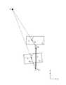
図2は、画像信号の一例を表す概念図である。
図2において、左右方向が水平方向(x軸)を表し、上下方向が垂直方向(y軸)を表す。図2は、前フレームk−1において撮影された画像と現フレームkにおいて撮影された画像を重ね合わせて表示した画像を表す。
図2の中央上方に破線で示す図形は、前フレームk−1において撮影された被写体として先行車両4を表す画像を表す。先行車両4は、情報提示装置1及びカメラ2を搭載する自自車両3の進行方向を走行している車両である。白抜きの丸印は、前フレームk−1における特徴点を表す。図2の中央下方に実線で示す図形は、現フレームkにおいて撮影された被写体として前方車両を表す画像を表す。黒塗りの丸印は、現フレームkにおける特徴点である。白抜きの丸印から黒塗りの丸印に向かう矢印は、白抜きの丸印が表す特徴点が黒塗りの丸印が表す特徴点に対応することを表す。即ち、前フレームk−1から現フレームkへの特徴点の移動を表す。なお、図2の左下に示す上方へ向かう矢印は、法線ベクトルnを表す。法線ベクトルnは、自車両3が走行する路面に対して垂直な方向を表すベクトルである。本実施形態では、到達時間算出部123に予め法線ベクトルnを設定させておく。Here, the change in the position of the feature point will be described.
FIG. 2 is a conceptual diagram illustrating an example of an image signal.
In FIG. 2, the left-right direction represents the horizontal direction (x-axis), and the up-down direction represents the vertical direction (y-axis). FIG. 2 shows an image displayed by superimposing the image captured in the previous frame k-1 and the image captured in the current frame k.
A figure indicated by a broken line in the upper center of FIG. 2 represents an image representing the preceding vehicle 4 as a subject photographed in the previous frame k-1. The preceding vehicle 4 is a vehicle traveling in the traveling direction of the host vehicle 3 on which the
図1に戻り、到達時間算出部123は、算出した方向ベクトルpk−1、pkに基づいて、回転行列Rを算出する。回転行列Rは、前フレームk−1におけるカメラ座標系の座標軸を、現フレームkにおけるカメラ座標系の座標軸への回転を表す行列である。なお、本実施形態における回転行列Rの算出方法の一例について、後述する。Returning to FIG. 1, the arrival
次に、方向ベクトルpk−1、pkと回転行列Rの関係について説明する。
図3は、本実施形態に係る自車両3と特徴点の位置関係の一例を表す概念図である。
図3の左右方向は、現フレームkにおけるカメラ2の光軸方向と垂直であって路面と平行な方向(X’方向)を表す。図3の上下方向は、現フレームkにおけるカメラ2の光軸方向(Z’方向)を表す。
図3の下方に示される図形は、前フレームk−1における自車両3を示す。ok−1は、前フレームk−1における座標の原点、つまりカメラ2の位置を示す。ok−1を起点とする左上方に向かう矢印は、方向ベクトルpk−1を表す。図3の中央に示す図形は、現フレームkにおける自車両3を示す。okは、現フレームkにおける座標の原点、つまりカメラ2の位置を示す。okを起点とする左上方に向かう矢印は、方向ベクトルpkを表す。図3の左上方に示す黒丸は、特徴点Aを示す。ok−1からokに向かう矢印は、並進ベクトルtを示す。即ち、図3では特徴点Aが静止し、カメラ2が相対的に移動していることを表す。Next, the relationship between the direction vectors pk−1 and pk and the rotation matrix R will be described.
FIG. 3 is a conceptual diagram illustrating an example of the positional relationship between the host vehicle 3 and feature points according to the present embodiment.
The left-right direction in FIG. 3 represents a direction (X ′ direction) perpendicular to the optical axis direction of the
The figure shown in the lower part of FIG. 3 shows the host vehicle 3 in the previous frame k-1. ok−1 indicates the origin of coordinates in the previous frame k−1, that is, the position of the
次に、方向ベクトルpk−1、pkと特徴点Aを表す画像との関係について説明する。
図4は、本実施形態に係るカメラ2の撮像面と特徴点の位置関係の一例を表す概念図である。
図4に示される上下、左右方向、特徴点A、原点ok−1、ok、方向ベクトルpk−1、pk、並進ベクトルtは、図3と同様である。
ここで、方向ベクトルpk−1の終点にある×印は、撮像面Ik−1における特徴点Aの位置を表す。撮像面Ik−1は、前フレームk−1においてカメラ2が撮影した画像である。xは、上述のように特徴点Aの水平方向の正規化された座標である。yは、上述のように特徴点Aの垂直方向の正規化された座標である。
ここで、方向ベクトルpkの終点にある×印は、撮像面Ikにおける特徴点Aの位置を表す。撮像面Ikは、現フレームkにおいてカメラ2が撮影した画像である。x’は、上述のように特徴点Aの水平方向の正規化された座標である。y‘は、上述のように特徴点Aの垂直方向の正規化された座標である。Next, the relationship between the direction vectors pk−1 and pk and the image representing the feature point A will be described.
FIG. 4 is a conceptual diagram illustrating an example of the positional relationship between the imaging surface of the
Vertical as shown in Figure 4, the lateral direction, the feature point A, the origino k-1, o k, the direction vectorp k-1, p k, the translation vector t are the same as in FIG.
Here, the x mark at the end point of the direction vector pk−1 represents the position of the feature point A on the imaging plane Ik−1 . The imaging surface Ik-1 is an image taken by the
Here, the × mark in the end of the direction vector pk, represents the position of the feature point A on the imaging plane Ik. The imaging surface Ik is an image taken by the
次に、上述のカメラ座標系の時間変化について説明する。
図5は、本実施形態に係るカメラ座標系の時間変化の一例を表す概念図である。
図5に示される上下、左右方向、原点ok−1、ok、並進ベクトルtは、図3、4と同様である。
図5の下方中央は、前フレームk−1におけるカメラ2のカメラ座標系の座標軸を表す。Z軸方向は、カメラ2の光軸方向を表す。X軸方向は、カメラ2の光軸方向に垂直であって水平面に平行な方向を表す。Y軸方向は、カメラ2の光軸方向に垂直であってX軸方向に垂直な方向を表す。
図5の中央は、現フレームkにおけるカメラ2のカメラ座標系の座標軸を表す。X’、Y’、Z’各軸方向は、図3と同様である。
並進ベクトルtの左方にある左回りの矢印は、カメラ座標系が前フレームk−1から現フレームkにかけて回転する方向を表す矢印である。回転行列Rは、この回転を定量的に表す行列である。Next, the time change of the camera coordinate system will be described.
FIG. 5 is a conceptual diagram illustrating an example of a time change of the camera coordinate system according to the present embodiment.
Vertical as shown in Figure 5, the horizontal direction, the origino k-1, o k, the translation vector t are the same as FIGS.
The lower center of FIG. 5 represents the coordinate axes of the camera coordinate system of the
The center of FIG. 5 represents the coordinate axes of the camera coordinate system of the
A counterclockwise arrow on the left side of the translation vector t is an arrow indicating a direction in which the camera coordinate system rotates from the previous frame k-1 to the current frame k. The rotation matrix R is a matrix that quantitatively represents this rotation.
図3に示されるように、方向ベクトルpkは、回転行列Rと方向ベクトルpk−1との間で、次式の関係を満足する。As shown in FIG. 3, the direction vector pk is between rotation matrix R and the direction vector pk-1, satisfies the following relationship.
式(4)において、Zは、前フレームk−1におけるカメラ2の光軸方向の座標である。Z’は、現フレームkにおけるカメラ2の光軸方向の座標である。tは、前フレームk−1における原点ok−1と、現フレームkにおける原点okの差分、つまり、カメラ2の位置の差分を表す並進ベクトルである。In Expression (4), Z is a coordinate in the optical axis direction of the
到達時間算出部123は、算出した回転行列Rに基づいて、現フレームkにおける距離Z’の前フレームk−1における距離Zに対する比Z’/Zを算出する。ここで、距離Z’は、現フレームkにおける特徴点のカメラ2の光軸方向の座標値である。距離Zは、前フレームk−1における特徴点のカメラ2の光軸方向の座標値である。
つまり、距離比Z’/Zは、前フレームk−1から現フレームkへの特徴点、即ちカメラ2から被写体までの距離の変化率を表す指標値である。距離比Z’/Zが0より大きく1よりも小さい値をとるとき、被写体に接近することを示す。ここで、距離比Z/Z’が小さいほど、被写体により早く接近することを示す。距離比Z’/Zが1の場合は、被写体までの距離が変化しないことを示す。距離比Z’/Zが1より大きい場合は、被写体から遠ざかることを示す。なお、到達時間算出部123は、距離比が0又は負の値をとる場合には、エラーと判定し、現フレームkにおける処理を中止する。
距離比Z’/Zを算出する際、到達時間算出部123は、例えば式(5)を用いる。Based on the calculated rotation matrix R, the arrival
That is, the distance ratio Z ′ / Z is an index value that represents the rate of change of the feature point from the previous frame k−1 to the current frame k, that is, the distance from the
When calculating the distance ratio Z ′ / Z, the arrival
式(5)において、Tはベクトル又は行列の転置を表す演算子である。式(5)は、方向ベクトルpk−1に回転行列Rを乗じて補正されたベクトルRpk−1と法線ベクトルnとの内積を、方向ベクトルpkと法線ベクトルnとの内積に対する比を、距離比Z’/Zとして算出することを示す。
式(5)を用いて、距離比Z’/Zを算出する原理については後述する。
到達時間算出部123は、到達時間TTCを距離比Z’/Zに基づいて、例えば式(6)を用いて算出する。In Expression (5), T is an operator representing transposition of a vector or a matrix. Equation (5) is obtained by calculating the inner product of the vector Rpk−1 corrected by multiplying the direction vector pk−1 by the rotation matrix R and the normal vector n to the inner product of the direction vector pk and the normal vector n. The ratio is calculated as a distance ratio Z ′ / Z.
The principle of calculating the distance ratio Z ′ / Z using equation (5) will be described later.
The arrival
式(6)において、ΔTは、フレーム間の時間間隔を示す。式(6)の分子は、フレーム間の間隔毎の、カメラ2から物体上の特徴点までの距離の変化率を表す。即ち、式(6)は、カメラ2が特徴点に到達するまでのフレーム数をフレーム間の時間間隔で正規化して、つまり到達時間として算出することを表す。
到達時間算出部123は、算出した到達時間を表す到達時間情報を警報判定部124に出力する。In Expression (6), ΔT represents a time interval between frames. The numerator of equation (6) represents the rate of change of the distance from the
The arrival
次に、本実施形態に係る情報提示処理について説明する。
図6は、本実施形態に係る情報提示処理を表すフローチャートである。
(ステップS101)物体検知部121及び特徴点抽出部122は、カメラ2から各々フレーム毎に画像信号を入力される。その後、ステップS102に進む。
(ステップS102)物体検知部121は、画像信号が表す物体を検知し、検知した物体が表された領域を示す物体情報を生成する。その後、ステップS103に進む。
(ステップS103)物体検知部121は、生成した物体情報から観測対象とする物体(例えば、先行車両)の物体情報を抽出する。物体検知部121は、抽出した物体の物体情報を特徴点抽出部122に出力する。その後、ステップS103に進む。Next, information presentation processing according to the present embodiment will be described.
FIG. 6 is a flowchart showing the information presentation process according to the present embodiment.
(Step S <b> 101) The
(Step S102) The
(Step S103) The
(ステップS104)特徴点抽出部122は、カメラ2から入力された画像信号から、物体検知部121から入力された物体情報が表す物体が表す領域の特徴点を抽出する。特徴点抽出部122は、抽出した特徴点の座標を表す特徴点情報を到達時間算出部123に出力する。その後、ステップS105に進む。
(ステップS105)到達時間算出部123は、特徴点抽出部122から入力された現フレームkの特徴点情報が表す特徴点から、前フレームk−1の特徴点情報が表す特徴点に対応する特徴点を選択する。本実施形態に係る特徴点選択処理の一例については後述する。
その後、ステップS106に進む。(Step S104) The feature
(Step S105) The arrival
Thereafter, the process proceeds to step S106.
(ステップS106)到達時間算出部123は、前フレームk−1における選択された特徴点までの方向ベクトルpk−1と、現フレームkの対応する特徴点までの方向ベクトルpkを算出する。到達時間算出部123は、算出した方向ベクトルpk−1、pkに基づいて、回転行列Rを算出する。その後、ステップS107に進む。
(ステップS107)到達時間算出部123は、算出した方向ベクトルpk−1、pk、回転行列R及び予め設定された法線ベクトルnに基づいて、例えば式(5)を用いて距離比Z’/Zを算出する。その後、ステップS108に進む。
(ステップS108)到達時間算出部123は、算出した距離比Z’/Zに基づいて、例えば式(6)を用いて到達時間TTCを算出する。到達時間算出部123は、算出した到達時間TTCを表す到達時間情報を警報判定部124に出力する。その後、ステップS109に進む。(Step S106) arrival
(Step S107) The arrival
(Step S108) The arrival
(ステップS109)警報判定部124は、到達時間算出部123から入力された到達時間情報に基づいて検知した物体に到達することを表す警報を出力するか否か判断する。警報を出力すると判断された場合(ステップS109 Y)、ステップS110に進む。警報を出力しないと判断された場合(ステップS109 N)、処理を終了する。
(ステップS110)警報判定部124は、警報を出力すると判断したとき、警報出力要求信号を生成し、生成した警報出力要求信号を警報出力部125に出力する。警報出力部125は、警報判定部124から警報出力要求信号が入力されたとき、警報情報を利用者が認知できる態様で表示する。その後、処理を終了する。
なお、上述のステップのうちステップS101−S108は、本実施形態に係る到達時間算出処理に該当する。(Step S109) The
(Step S <b> 110) When the
Of the above-described steps, steps S101 to S108 correspond to the arrival time calculation process according to the present embodiment.
次に、本実施形態において、到達時間算出部123が行う現フレームkにおける特徴点に対応する前フレームk−1における特徴点を探索する処理について説明する。
図7は、本実施形態に係る特徴点探索処理を示すフローチャートである。
(ステップS201)到達時間算出部123は、前フレームk−1から現フレームkまでの各特徴点の物体毎の並進ベクトルの初期値を、例えばゼロと設定する。到達時間算出部123は、この初期値を、ゼロの代わりに前回算出した並進移動量(例えば、フレームk−2からフレームk−1までの特徴量間の並進移動量)を設定してもよい。また、到達時間算出部123は、現フレームkの特徴点から前フレームk−1の特徴点を探索する範囲を設定する。その後、ステップS202に進む。Next, in the present embodiment, a process for searching for a feature point in the previous frame k−1 corresponding to a feature point in the current frame k performed by the arrival
FIG. 7 is a flowchart showing the feature point search processing according to the present embodiment.
(Step S201) The arrival
(ステップS202)到達時間算出部123は、各特徴点の物体毎の並進移動量が設定した値の範囲内か否かを判断する。到達時間算出部123は、並進移動量が設定した値の範囲内と判断したとき(ステップS202 Y)、ステップS206に進む。到達時間算出部123は、物体毎の並進移動量が設定した値の範囲内ではないと判断したとき(ステップS202 N)、ステップS203に進む。(Step S202) The arrival
(ステップS203)到達時間算出部123は、前フレームk−1の各特徴点の座標に、物体毎の並進移動量を加算して現フレームkの各特徴点の座標を推定する。その後、ステップS204に進む。
(ステップS204)到達時間算出部123は、ステップS203において推定した現フレームkの特徴点から予め設定された距離よりも近接する領域(特徴点近傍)にあるサンプル点の補間画素値と前フレームk−1での特徴点近傍にあるサンプル点の補間画素値の差分を、各サンプル点について算出する。前フレームk−1のサンプル点は、例えば、前フレームt−1での特徴点近傍に含まれる各画素の中心点である。現フレームkのサンプル点は、前フレームk−1でのサンプル点に並進移動量を加算して推定した座標である。特徴点は必ずしも各画素の中心点上にあるとは限らないため、到達時間算出部123は、各フレームにおいて当該補間画素値を、特徴点近傍にある各画素の中心点と特徴点の位置関係に基づいて算出する。その後、ステップS205に進む。
(ステップS205)到達時間算出部123は、ステップS204において算出した差分について、その二乗和を最小化する並進移動量を、例えば非線形最小二乗法を用いて算出することで並進移動量を更新する。その後、ステップS202に進む。(Step S203) The arrival
(Step S204) The arrival
(Step S205) The arrival
(ステップS206)到達時間算出部123は、ステップS205において算出した差分に基づく二乗和を最小化する前フレームk−1の特徴点を、現フレームkの特徴点に各々対応する前フレームk−1の特徴点と決定する。なお、到達時間算出部123は、この過程で得られた並進移動量を並進ベクトルtと定める。その後、処理を終了する。(Step S206) The arrival
次に、本実施形態において、回転行列Rを算出する方法の一例について説明する。
回転行列Rは、例えば、式(7)で示される3行3列の行列である。Next, an example of a method for calculating the rotation matrix R in the present embodiment will be described.
The rotation matrix R is, for example, a 3 × 3 matrix represented by Expression (7).
式(7)において、θZは、現フレームkにおけるカメラ2の光軸方向の座標軸(Z’軸)回りの回転角である。θXは、現フレームkにおけるカメラ2の光軸と垂直であって、水平面に平行な座標軸(X’軸)回りの回転角である。θYは、フレームkにおけるカメラ2の光軸と垂直であって、X’軸と垂直な座標軸(Y’軸)回りの回転角である。従って、式(7)に示される回転行列Rの行列式は1となる。
そして、方向ベクトルpk−1、pkと回転行列R並びに並進ベクトルtは、式(8)で表される関係がある。In the formula (7), thetaZ is the rotation angle of the optical axis direction of the coordinate axis (Z 'axis) around the
The direction vectors pk−1 and pk , the rotation matrix R, and the translation vector t have a relationship represented by Expression (8).
式(8)において、×は、3次元ベクトルの外積を表す。式(8)で表される関係はエピポーラ条件と呼ばれる。即ち、式(8)は、3つの3次元ベクトルRpk−1、pk及び並進ベクトルtが同一平面上にあるときの条件を表す。外積t×Rpk−1は、ベクトルtとRpk−1に張られる平面の法線を表し、方向ベクトルpkもこの平面に含まれるならば法線との内積が0となることを表す。
そこで、到達時間算出部123は、5個以上の特徴点について、例えば式(8)の左辺の二乗和が最小となるような回転行列Rと並進ベクトルを非線形最小二乗法を用いて算出する。但し、算出過程において、回転行列Rの各成分が、例えば式(7)に示す関係を保つようにする。このようにして、到達時間算出部123は、回転行列Rを算出することができる。In Expression (8), x represents the outer product of three-dimensional vectors. The relationship represented by Expression (8) is called an epipolar condition. That is, Expression (8) represents a condition when the three three-dimensional vectors Rpk−1 , pk and the translation vector t are on the same plane. The outer product t × Rpk−1 represents the normal line of the plane spanned by the vectors t and Rpk−1 , and the inner product with the normal line is 0 if the direction vectorpk is also included in this plane. .
Accordingly, the arrival
次に、到達時間算出部123が、式(5)を用いて距離比Z’/Zを算出する原理について説明する。
並進ベクトルtは、前フレームk−1における自車両3の位置と現フレームkにおける自車両3の位置との差を表す。従って、並進ベクトルtは、自車両3が走行する路面に垂直な方向を表す法線ベクトルnと近似的に直交する。
従って、式(4)の両辺に法線ベクトルnとの内積をとると、式(4)の右辺第2項がゼロとなり、式(9)が導かれる。Next, the principle by which the arrival
The translation vector t represents the difference between the position of the host vehicle 3 in the previous frame k-1 and the position of the host vehicle 3 in the current frame k. Accordingly, the translation vector t is approximately orthogonal to the normal vector n representing the direction perpendicular to the road surface on which the host vehicle 3 travels.
Therefore, if the inner product of the normal vector n is taken on both sides of the equation (4), the second term on the right side of the equation (4) becomes zero, and the equation (9) is derived.
そして、式(9)の両辺をZ・nTpkで除算すれば式(2)を導くことができる。Then, by dividing both sides of equation (9) by Z · nT pk , equation (2) can be derived.
上述では、現フレームの画像信号と、1フレーム過去に撮影された前フレームの画像信号(計2フレーム)を用いて、到達時間算出部123が物体に到達するまでの到達時間を算出する例について説明した。本実施形態では、これには限られない。例えば、到達時間算出部123が算出した現フレーム時刻kにおける到達時間TTC(k)から(M−1)フレームだけ過去の時刻k−(M−1)における到達時間TTC(k−(M−1))の平均値(例えば、移動平均値)を、現フレーム時刻kにおける到達時間TTC(k)として算出してもよい。これによって、到達時間算出部123を備える自車両3が位置する路面の凸凹や物体(被写体)が走行する路面の凸凹による影響が平滑化され、より高い精度で到達時間TTCを算出することができる。 In the above-described example, the arrival time until the arrival
このように、本実施形態では、画像信号をフレーム毎に入力し、入力された画像信号が表す物体を検知し、検知した物体までの方向を表す方向ベクトルに基づいて前記画像信号を撮影した撮影装置の光軸の回転を表す回転行列を算出し、過去の方向ベクトルに前記算出した回転行列を乗じたベクトルと、現在の方向ベクトルとに基づいて前記物体までの距離の変化を算出する。これにより、物体が進行方向の遠方にあっても、物体の方向の変化に基づく誤差が抑制される。そのため、障害物等の物体までの到達時間の推定精度を向上することができる。 As described above, in this embodiment, an image signal is input for each frame, an object represented by the input image signal is detected, and the image signal is captured based on a direction vector representing a direction to the detected object. A rotation matrix representing the rotation of the optical axis of the apparatus is calculated, and a change in distance to the object is calculated based on a vector obtained by multiplying a past direction vector by the calculated rotation matrix and a current direction vector. Thereby, even if the object is far from the traveling direction, an error based on a change in the direction of the object is suppressed. Therefore, the estimation accuracy of the arrival time to an object such as an obstacle can be improved.
また、本実施形態では、算出した到達時間に基づいて、検知した物体に到達することを表す情報を出力するか否かを判断する。
これにより、検知された物体に到達する可能性やその時刻を利用者に対してより確実に通知することができる。In the present embodiment, it is determined whether or not to output information indicating arrival at the detected object based on the calculated arrival time.
Thereby, the possibility of reaching the detected object and its time can be notified to the user more reliably.
なお、上述した実施形態における情報提示装置11の一部、例えば、物体検知部121、特徴点抽出部122、到達時間算出部123及び警報判定部124をコンピュータで実現するようにしても良い。その場合、この制御機能を実現するためのプログラムをコンピュータ読み取り可能な記録媒体に記録して、この記録媒体に記録されたプログラムをコンピュータシステムに読み込ませ、実行することによって実現しても良い。なお、ここでいう「コンピュータシステム」とは、情報提示装置11に内蔵されたコンピュータシステムであって、OSや周辺機器等のハードウェアを含むものとする。また、「コンピュータ読み取り可能な記録媒体」とは、フレキシブルディスク、光磁気ディスク、ROM、CD−ROM等の可搬媒体、コンピュータシステムに内蔵されるハードディスク等の記憶装置のことをいう。さらに「コンピュータ読み取り可能な記録媒体」とは、インターネット等のネットワークや電話回線等の通信回線を介してプログラムを送信する場合の通信線のように、短時間、動的にプログラムを保持するもの、その場合のサーバやクライアントとなるコンピュータシステム内部の揮発性メモリのように、一定時間プログラムを保持しているものも含んでも良い。また上記プログラムは、前述した機能の一部を実現するためのものであっても良く、さらに前述した機能をコンピュータシステムにすでに記録されているプログラムとの組み合わせで実現できるものであっても良い。
また、上述した実施形態における情報提示装置11装置の一部、または全部を、LSI(Large Scale Integration)等の集積回路として実現しても良い。情報提示装置11の各機能ブロックは個別にプロセッサ化してもよいし、一部、または全部を集積してプロセッサ化しても良い。また、集積回路化の手法はLSIに限らず専用回路、または汎用プロセッサで実現しても良い。また、半導体技術の進歩によりLSIに代替する集積回路化の技術が出現した場合、当該技術による集積回路を用いても良い。In addition, you may make it implement | achieve a part of the
Moreover, you may implement | achieve part or all of the
以上、図面を参照してこの発明の一実施形態について詳しく説明してきたが、具体的な構成は上述のものに限られることはなく、この発明の要旨を逸脱しない範囲内において様々な設計変更等をすることが可能である。 As described above, the embodiment of the present invention has been described in detail with reference to the drawings. However, the specific configuration is not limited to the above, and various design changes and the like can be made without departing from the scope of the present invention. It is possible to
11…情報提示装置、12…到達時間推定部、121…物体検知部、
122…特徴点抽出部、123…到達時間算出部、124…警報判定部、
125…警報出力部DESCRIPTION OF
122 ... feature point extraction unit, 123 ... arrival time calculation unit, 124 ... alarm determination unit,
125 ... Alarm output section
Claims (5)
Translated fromJapanese前記画像入力部から入力された画像信号が表す物体を検知する物体検知部と、
前記物体検知部が検知した物体までの方向を表す方向ベクトルに基づいて前記画像信号を撮影した撮影装置の光軸の回転を表す回転行列を算出し、過去の方向ベクトルに前記算出した回転行列を乗じたベクトルと、現在の方向ベクトルとに基づいて前記物体までの距離の変化を算出し、算出した距離の変化に基づいて当該物体までの到達時間を算出する到達時間算出部と、を備えること
を特徴とする到達時間推定装置。An image input unit for inputting an image signal for each frame;
An object detection unit for detecting an object represented by the image signal input from the image input unit;
Based on a direction vector that represents the direction to the object detected by the object detection unit, a rotation matrix that represents rotation of the optical axis of the imaging apparatus that captured the image signal is calculated, and the calculated rotation matrix is used as a past direction vector. An arrival time calculation unit that calculates a change in the distance to the object based on the multiplied vector and the current direction vector, and calculates an arrival time to the object based on the calculated change in distance. An arrival time estimation device characterized by the above.
前記到達時間算出部は、前記特徴点抽出部が抽出した特徴点の方向を、前記物体までの方向として前記到達時間を算出すること
を特徴とする請求項1に記載の到達時間推定装置。A feature point extraction unit that extracts a feature point on the object detected by the object detection unit from the image signal input from the image input unit;
The arrival time estimation device according to claim 1, wherein the arrival time calculation unit calculates the arrival time using the direction of the feature point extracted by the feature point extraction unit as the direction to the object.
前記画像入力部から入力された画像信号が表す物体を検知する物体検知部と、
前記物体検知部が検知した物体までの方向を表す方向ベクトルに基づいて前記画像信号を撮影した撮影装置の光軸の回転を表す回転行列を算出し、過去の方向ベクトルに前記算出した回転行列を乗じたベクトルと、現在の方向ベクトルとに基づいて前記物体までの距離の変化を算出し、算出した距離の変化に基づいて当該物体までの到達時間を算出する到達時間算出部と
前記到達時間算出部が算出した到達時間に基づいて、前記物体検知部が検知した物体に到達することを表す情報を出力するか否かを判断する出力判定部を備えること
を特徴とする情報提示装置。An image input unit for inputting an image signal for each frame;
An object detection unit for detecting an object represented by the image signal input from the image input unit;
Based on a direction vector that represents the direction to the object detected by the object detection unit, a rotation matrix that represents rotation of the optical axis of the imaging apparatus that captured the image signal is calculated, and the calculated rotation matrix is used as a past direction vector. An arrival time calculation unit that calculates a change in the distance to the object based on the multiplied vector and the current direction vector, and calculates an arrival time to the object based on the calculated change in the distance; and the arrival time calculation An information presentation device comprising: an output determination unit that determines whether or not to output information indicating that the object detection unit has reached the object detected based on the arrival time calculated by the unit.
前記到達時間推定装置が、画像信号をフレーム毎に入力する過程と、
前記到達時間推定装置が、前記入力された画像信号が表す物体を検知する過程と、
前記到達時間推定装置が、前記検知した物体までの方向を表す方向ベクトルに基づいて前記画像信号を撮影した撮影装置の光軸の回転を表す回転行列を算出し、過去の方向ベクトルに前記算出した回転行列を乗じたベクトルと、現在の方向ベクトルとに基づいて前記物体までの距離の変化を算出し、算出した距離の変化に基づいて当該物体までの到達時間を算出する過程と、を有すること
を特徴とする到達時間推定方法。In the arrival time estimation method in the arrival time estimation device,
The arrival time estimation device, a process of inputting an image signal for each frame;
A process in which the arrival time estimation device detects an object represented by the input image signal;
The arrival time estimation device calculates a rotation matrix that represents the rotation of the optical axis of the imaging device that captured the image signal based on the direction vector that represents the direction to the detected object, and the calculation is performed on the past direction vector. Calculating a change in the distance to the object based on a vector multiplied by a rotation matrix and a current direction vector, and calculating an arrival time to the object based on the calculated change in distance. An arrival time estimation method characterized by:
画像信号をフレーム毎に入力する手順と、
前記入力された画像信号が表す物体を検知する手順と、
前記検知した物体までの方向を表す方向ベクトルに基づいて前記画像信号を撮影した撮影装置の光軸の回転を表す回転行列を算出し、過去の方向ベクトルに前記算出した回転行列を乗じたベクトルと、現在の方向ベクトルとに基づいて前記物体までの距離の変化を算出し、算出した距離の変化に基づいて当該物体までの到達時間を算出する手順と、
を実行させるための到達時間推定プログラム。In the computer of the arrival time estimation device,
A procedure for inputting an image signal for each frame;
Detecting an object represented by the input image signal;
Based on a direction vector that represents the direction to the detected object, a rotation matrix that represents rotation of the optical axis of the imaging apparatus that captured the image signal is calculated, and a vector obtained by multiplying the past direction vector by the calculated rotation matrix; Calculating a change in distance to the object based on the current direction vector and calculating an arrival time to the object based on the calculated change in distance;
The arrival time estimation program for running.
Priority Applications (2)
| Application Number | Priority Date | Filing Date | Title |
|---|---|---|---|
| JP2011241466AJP2013097676A (en) | 2011-11-02 | 2011-11-02 | Arrival time estimation device, arrival time estimation method, arrival time estimation program and information presentation device |
| US13/666,707US20130142388A1 (en) | 2011-11-02 | 2012-11-01 | Arrival time estimation device, arrival time estimation method, arrival time estimation program, and information providing apparatus |
Applications Claiming Priority (1)
| Application Number | Priority Date | Filing Date | Title |
|---|---|---|---|
| JP2011241466AJP2013097676A (en) | 2011-11-02 | 2011-11-02 | Arrival time estimation device, arrival time estimation method, arrival time estimation program and information presentation device |
Publications (1)
| Publication Number | Publication Date |
|---|---|
| JP2013097676Atrue JP2013097676A (en) | 2013-05-20 |
Family
ID=48524034
Family Applications (1)
| Application Number | Title | Priority Date | Filing Date |
|---|---|---|---|
| JP2011241466APendingJP2013097676A (en) | 2011-11-02 | 2011-11-02 | Arrival time estimation device, arrival time estimation method, arrival time estimation program and information presentation device |
Country Status (2)
| Country | Link |
|---|---|
| US (1) | US20130142388A1 (en) |
| JP (1) | JP2013097676A (en) |
Cited By (2)
| Publication number | Priority date | Publication date | Assignee | Title |
|---|---|---|---|---|
| JPWO2017006451A1 (en)* | 2015-07-08 | 2018-04-19 | 日産自動車株式会社 | Lamp detection device and lamp detection method |
| US20210142677A1 (en)* | 2018-07-16 | 2021-05-13 | Celepixel Technology Co. Ltd | Method for calculating time to collision for object and vehicle, calculation device and vehicle |
Families Citing this family (3)
| Publication number | Priority date | Publication date | Assignee | Title |
|---|---|---|---|---|
| US9558555B2 (en) | 2013-02-22 | 2017-01-31 | Leap Motion, Inc. | Adjusting motion capture based on the distance between tracked objects |
| US9733715B2 (en) | 2013-03-15 | 2017-08-15 | Leap Motion, Inc. | Resource-responsive motion capture |
| JP2022173682A (en)* | 2021-05-10 | 2022-11-22 | ソニーグループ株式会社 | Mobile body, movement control method and program |
Family Cites Families (8)
| Publication number | Priority date | Publication date | Assignee | Title |
|---|---|---|---|---|
| JP3779280B2 (en)* | 2003-03-28 | 2006-05-24 | 富士通株式会社 | Collision prediction device |
| US7797107B2 (en)* | 2003-09-16 | 2010-09-14 | Zvi Shiller | Method and system for providing warnings concerning an imminent vehicular collision |
| EP2068269A3 (en)* | 2004-04-08 | 2009-10-07 | Mobileye Technologies Limited | Collision warning system |
| JP4539348B2 (en)* | 2004-09-07 | 2010-09-08 | 日産自動車株式会社 | Collision time calculation device and obstacle detection device |
| JP4544028B2 (en)* | 2005-05-13 | 2010-09-15 | 日産自動車株式会社 | In-vehicle image processing apparatus and image processing method |
| JP2008203992A (en)* | 2007-02-16 | 2008-09-04 | Omron Corp | Detection apparatus and method, and program |
| US8254635B2 (en)* | 2007-12-06 | 2012-08-28 | Gideon Stein | Bundling of driver assistance systems |
| JP5372680B2 (en)* | 2009-09-24 | 2013-12-18 | 日立オートモティブシステムズ株式会社 | Obstacle detection device |
- 2011
- 2011-11-02JPJP2011241466Apatent/JP2013097676A/enactivePending
- 2012
- 2012-11-01USUS13/666,707patent/US20130142388A1/ennot_activeAbandoned
Cited By (5)
| Publication number | Priority date | Publication date | Assignee | Title |
|---|---|---|---|---|
| JPWO2017006451A1 (en)* | 2015-07-08 | 2018-04-19 | 日産自動車株式会社 | Lamp detection device and lamp detection method |
| US10074022B2 (en) | 2015-07-08 | 2018-09-11 | Nissan Motor Co., Ltd. | Lamp detection device and lamp detection method |
| KR101920186B1 (en)* | 2015-07-08 | 2018-11-19 | 닛산 지도우샤 가부시키가이샤 | Equalizer detection device and equalizer detection method |
| US20210142677A1 (en)* | 2018-07-16 | 2021-05-13 | Celepixel Technology Co. Ltd | Method for calculating time to collision for object and vehicle, calculation device and vehicle |
| US11893891B2 (en)* | 2018-07-16 | 2024-02-06 | Omnivision Sensor Solution (Shanghai) Co., Ltd | Method for calculating time to collision for object and vehicle, calculation device and vehicle |
Also Published As
| Publication number | Publication date |
|---|---|
| US20130142388A1 (en) | 2013-06-06 |
Similar Documents
| Publication | Publication Date | Title |
|---|---|---|
| KR20210107570A (en) | Method for estimating ego motion of an object | |
| US10762643B2 (en) | Method for evaluating image data of a vehicle camera | |
| US11132810B2 (en) | Three-dimensional measurement apparatus | |
| US9953461B2 (en) | Navigation system applying augmented reality | |
| JP6107081B2 (en) | Image processing apparatus, image processing method, and program | |
| JP4970926B2 (en) | Vehicle periphery monitoring device | |
| KR101776621B1 (en) | Apparatus for recognizing location mobile robot using edge based refinement and method thereof | |
| JP2013097675A (en) | Gradient estimation device, gradient estimation method, and gradient estimation program | |
| US9122936B2 (en) | Detecting device, detection method, and computer program product | |
| US10438412B2 (en) | Techniques to facilitate accurate real and virtual object positioning in displayed scenes | |
| KR20150144726A (en) | Apparatus for recognizing location mobile robot using search based correlative matching and method thereof | |
| JP2013097676A (en) | Arrival time estimation device, arrival time estimation method, arrival time estimation program and information presentation device | |
| CN111788533A (en) | Method and system for vehicle pose estimation based on stereo vision | |
| JP2014106901A (en) | Distance calculation device, collision detection system, distance calculation method, collision detection method, and program | |
| JP2012113414A (en) | Part detection apparatus, part detection method and program | |
| US20110267430A1 (en) | Detection Device of Planar Area and Stereo Camera System | |
| JP6188860B1 (en) | Object detection device | |
| JP2011209070A (en) | Image processor | |
| US11282223B2 (en) | Signal processing apparatus, signal processing method, and imaging apparatus | |
| JP5251460B2 (en) | Approaching object detection device, approaching object detection program, approaching object detection method | |
| EP4435721A1 (en) | Information processing device, information processing method, and program | |
| KR101574020B1 (en) | Method and Apparatus for stereo rectification of left and right view images captured from stereo cameras | |
| KR20170122508A (en) | Coordination guide method and system based on multiple marker | |
| US20220343536A1 (en) | Three-dimensional map estimation apparatus and obstacle detection apparatus | |
| JP5113867B2 (en) | Vehicle periphery monitoring device |