Movatterモバイル変換


[0]ホーム

URL:


JP2013097621A - Drive support device - Google Patents

Drive support device
Download PDF

Info

Publication number
JP2013097621A
JP2013097621AJP2011240590AJP2011240590AJP2013097621AJP 2013097621 AJP2013097621 AJP 2013097621AJP 2011240590 AJP2011240590 AJP 2011240590AJP 2011240590 AJP2011240590 AJP 2011240590AJP 2013097621 AJP2013097621 AJP 2013097621A
Authority
JP
Japan
Prior art keywords
vehicle speed
driving support
control unit
driving
target vehicle
Prior art date
Legal status (The legal status is an assumption and is not a legal conclusion. Google has not performed a legal analysis and makes no representation as to the accuracy of the status listed.)
Pending
Application number
JP2011240590A
Other languages
Japanese (ja)
Inventor
Yuki Yamada
友希 山田
Current Assignee (The listed assignees may be inaccurate. Google has not performed a legal analysis and makes no representation or warranty as to the accuracy of the list.)
Toyota Motor Corp
Original Assignee
Toyota Motor Corp
Priority date (The priority date is an assumption and is not a legal conclusion. Google has not performed a legal analysis and makes no representation as to the accuracy of the date listed.)
Filing date
Publication date
Application filed by Toyota Motor CorpfiledCriticalToyota Motor Corp
Priority to JP2011240590ApriorityCriticalpatent/JP2013097621A/en
Priority to DE102012219919.5Aprioritypatent/DE102012219919B4/en
Priority to US13/666,381prioritypatent/US20130110371A1/en
Publication of JP2013097621ApublicationCriticalpatent/JP2013097621A/en
Pendinglegal-statusCriticalCurrent

Links

Images

Classifications

Landscapes

Abstract

Translated fromJapanese

【課題】運運転者に与える負荷を少なくしつつ、適切に運転を支援することができる運転支援装置を提供すること。
【解決手段】車両の運転を支援する運転支援装置であって、車両の走行速度を検出する車速センサと、許容加速度および許容減速度の少なくとも一方および車速センサで検出した現車速に基づいて推奨走行状態を決定する走行支援制御部と、走行支援制御部で決定した推奨走行状態を通知する目標車速通知部と、を有し、走行支援制御部は、現車速を基準として、現車速から許容加速度で加速した場合および現車速から許容減速度で減速した場合の少なくとも一方の範囲に基づいて推奨走行状態を決定する。
【選択図】図2
To provide a driving support device capable of appropriately supporting driving while reducing a load applied to an operating driver.
A driving support device for supporting driving of a vehicle, the vehicle speed sensor for detecting the traveling speed of the vehicle, at least one of the allowable acceleration and the allowable deceleration, and the recommended driving based on the current vehicle speed detected by the vehicle speed sensor. A driving support control unit that determines the state, and a target vehicle speed notification unit that notifies the recommended driving state determined by the driving support control unit. The driving support control unit uses the current vehicle speed as a reference and the allowable acceleration from the current vehicle speed. The recommended travel state is determined based on at least one of the range when the vehicle is accelerated in step 1 and when the vehicle is decelerated with an allowable deceleration from the current vehicle speed.
[Selection] Figure 2

Description

Translated fromJapanese

本発明は、運転支援装置に関する。  The present invention relates to a driving support device.

近年、自動車等の車両には、運転者による運転を支援する運転支援装置を搭載しているものがある。例えば、特許文献1および特許文献2には、車両の走行状態および信号機の状態に基づいて、交差点を適切に通行できるように走行の支援を行う運転支援装置が記載されている。例えば、特許文献1には、表示画面上に固定表示された基準値としての推奨走行速度あるいは修正推奨走行速度に対して、車両の実走行速度を基準値との相対値として比較表示することを特徴とする交差点無停止走行制御システム用車両速度表示方法が記載されている。また、特許文献2には、停止線までの距離、自車両の速度、交差点に設置された信号機の黄信号開始時点及び黄信号時間及び所定の標準減速度などに基づいて、自車両が交差点の手前に停止するための停止条件及び交差点に進入するための進入条件により決定される危険走行状態にあるか否かを判定する車載装置が記載されている。車載装置は、危険走行状態にあると判定した場合、危険走行状態を回避するために、例えば、車両を停止線に停止させる場合には、車両を緩やかな減速度で減速するための処理を行い、あるいは、車両を交差点に進入させる場合には、車両を緩やかな加速度で加速するための処理を行う。  In recent years, some vehicles such as automobiles are equipped with a driving assistance device that assists driving by a driver. For example, Patent Literature 1 and Patent Literature 2 describe a driving assistance device that supports traveling so that an intersection can be appropriately passed based on the traveling state of a vehicle and the state of a traffic light. For example, in Patent Document 1, the actual traveling speed of the vehicle is compared and displayed as a relative value with respect to the reference value with respect to the recommended traveling speed or the corrected recommended traveling speed that is fixedly displayed on the display screen. A characteristic vehicle speed display method for an intersection non-stop traveling control system is described. Patent Document 2 discloses that the own vehicle is located at the intersection based on the distance to the stop line, the speed of the own vehicle, the yellow signal start time and yellow signal time of the traffic light installed at the intersection, the predetermined standard deceleration, and the like. There is described an in-vehicle device that determines whether or not the vehicle is in a dangerous driving state determined by a stop condition for stopping before and an entry condition for entering an intersection. If the in-vehicle device determines that the vehicle is in a dangerous driving state, for example, when the vehicle is stopped on a stop line, a process for decelerating the vehicle at a slow deceleration is performed in order to avoid the dangerous driving state. Or when making a vehicle approach an intersection, the process for accelerating a vehicle with a moderate acceleration is performed.

特開2009−289007号公報JP 2009-289007 A特開2008−296783号公報JP 2008-296783 A

特許文献1または特許文献2に記載の装置は、推奨走行速度を表示したり、加速や減速を即す情報を出力したりすることで、運転者に信号を通過できる走行条件を通知したり、交差点を安全に通過することができる。しかしながら、特許文献1または特許文献2に記載の装置は、表示する目標の走行速度や加速の指示が、現状の走行状態と目標の加速、走行速度との条件の差が大きく、条件を満足する走行を行うためには厳しい条件で操縦をすることが必要な場合がある。このように、運転者は、厳しい条件での操縦が誘導される可能性があると、表示される支援情報に対して心理的な負担を感じる恐れがある。  The device described in Patent Document 1 or Patent Document 2 displays a recommended traveling speed, or outputs information for accelerating or decelerating to notify the driver of a traveling condition that allows a signal to pass through. You can pass through the intersection safely. However, in the apparatus described in Patent Document 1 or Patent Document 2, the target traveling speed and acceleration instruction to be displayed satisfy the conditions because the difference between the current traveling state and the target acceleration and traveling speed is large. In order to run, it may be necessary to maneuver under severe conditions. As described above, the driver may feel a psychological burden on the displayed support information if there is a possibility that the maneuvering under severe conditions may be guided.

本発明の目的は、運転者に与える負荷を少なくしつつ、適切に運転を支援することができる運転支援装置を提供することである。  The objective of this invention is providing the driving assistance apparatus which can support driving | operation appropriately, reducing the load given to a driver | operator.

本発明は、車両の運転を支援する運転支援装置であって、車両の運転を支援する運転支援装置であって、前記車両の走行速度を検出する車速センサと、許容加速度および許容減速度の少なくとも一方および前記車速センサで検出した現車速に基づいて推奨走行状態を決定する走行支援制御部と、前記走行支援制御部で決定した前記推奨走行状態を通知する目標車速通知部と、を有し、前記走行支援制御部は、前記現車速を基準として、前記現車速から前記許容加速度で加速した場合および前記現車速から前記許容減速度で減速した場合の少なくとも一方の範囲に基づいて推奨走行状態を決定することを特徴とする。  The present invention is a driving support device that supports driving of a vehicle, and is a driving support device that supports driving of the vehicle, and includes a vehicle speed sensor that detects a traveling speed of the vehicle, and at least an allowable acceleration and an allowable deceleration. One and a driving support control unit that determines a recommended driving state based on the current vehicle speed detected by the vehicle speed sensor, and a target vehicle speed notification unit that notifies the recommended driving state determined by the driving support control unit, The travel support control unit determines a recommended travel state based on at least one of a range when the vehicle is accelerated from the current vehicle speed with the allowable acceleration and a case where the vehicle is decelerated from the current vehicle speed with the allowable deceleration. It is characterized by determining.

また、前記車両の走行方向に配置された信号機の表示が切り替わるサイクルである信号サイクルの情報を取得するインフラ通信部と、前記信号機が配置された信号機地点との相対位置情報を検出する位置算出部と、をさらに有し、前記走行支援制御部は、前記許容加速度および前記許容減速度の少なくとも一方、前記現車速、前記相対位置情報および前記インフラ通信部で取得した信号サイクルの情報に基づいて、前記推奨走行状態を決定することが好ましい。  Further, a position calculation unit that detects relative position information between an infrastructure communication unit that acquires information on a signal cycle that is a cycle in which a display of a traffic signal arranged in the traveling direction of the vehicle is switched, and a traffic signal point where the traffic signal is arranged And the driving support control unit is based on at least one of the allowable acceleration and the allowable deceleration, the current vehicle speed, the relative position information, and the signal cycle information acquired by the infrastructure communication unit, It is preferable to determine the recommended traveling state.

また、前記走行支援制御部は、前記信号機に表示される灯色に応じて、前記許容加速度および前記許容減速度の少なくとも一方を変更することが好ましい。  Moreover, it is preferable that the said driving assistance control part changes at least one of the said allowable acceleration and the said allowable deceleration according to the lamp color displayed on the said traffic light.

また、前記走行支援制御部は、前記現車速で走行した場合に前記信号機地点に到達する到着タイミングと、前記現車速から前記許容加速度で加速して走行した場合に前記信号機地点に到達する加速到着タイミングと、を検出し、前記加速到着タイミングから前記到着タイミングまでの間に、前記信号機が通過可能な表示が含まれる場合、前記信号機が配置された信号機地点を前記車両が通過できる速度域を目標車速域として決定することが好ましい。  In addition, the travel support control unit may arrive at the traffic light point when traveling at the current vehicle speed, and accelerate arrival at the traffic signal point when traveling at the allowable acceleration from the current vehicle speed. And when the indication that the signal can pass is included between the acceleration arrival timing and the arrival timing, the target is a speed range in which the vehicle can pass through the traffic signal point where the signal is arranged. It is preferable to determine the vehicle speed range.

また、前記走行支援制御部は、前記加速到着タイミングで前記信号機地点に到達する車速を前記目標車速域の最高速度とすることが好ましい。  Further, it is preferable that the travel support control unit sets a vehicle speed that reaches the traffic light point at the acceleration arrival timing as a maximum speed in the target vehicle speed range.

また、前記走行支援制御部は、前記現車速で走行した場合に前記信号機地点に到達する到着タイミングと、前記現車速から前記許容減速度で減速して走行した場合に前記信号機地点に到達する減速到着タイミングと、を検出し、前記到着タイミングから前記減速到着タイミングまでの間に、前記信号機が通過可能な表示が含まれる場合、前記信号機が配置された信号機地点を前記車両が通過できる速度域を前記目標車速域として決定することが好ましい。  The travel support control unit may arrive at the traffic light point when traveling at the current vehicle speed, and the deceleration reaching the traffic signal point when traveling at the allowable deceleration from the current vehicle speed. When an indication that the traffic light can pass is included between the arrival timing and the deceleration arrival timing, a speed range in which the vehicle can pass through the traffic light point where the traffic light is arranged is detected. It is preferable to determine the target vehicle speed range.

また、前記走行支援制御部は、前記減速到着タイミングで前記信号機地点に到達する車速を前記目標車速域の最低速度とすることが好ましい。  Moreover, it is preferable that the driving support control unit sets a vehicle speed that reaches the traffic light point at the deceleration arrival timing as a minimum speed in the target vehicle speed range.

また、前記走行支援制御部は、制限車速の情報を備え、前記制限車速を超えない車速範囲で前記推奨走行状態を決定することが好ましい。  In addition, it is preferable that the travel support control unit includes information on a limited vehicle speed and determines the recommended travel state within a vehicle speed range that does not exceed the limit vehicle speed.

また、前記走行支援制御部は、前記推奨走行状態として、車速の範囲の情報である目標車速域を決定することが好ましい。  Moreover, it is preferable that the said driving assistance control part determines the target vehicle speed range which is the information of the range of vehicle speed as the said recommended driving state.

また、前記目標車速通知部は、前記目標車速域を表示する目標車速表示部であることが好ましい。  Moreover, it is preferable that the said target vehicle speed notification part is a target vehicle speed display part which displays the said target vehicle speed range.

本発明にかかる運転支援装置は、運転者に与える負荷を少なくしつつ、適切に運転を支援することができるという効果を奏する。  The driving support device according to the present invention has an effect that driving can be appropriately supported while reducing the load applied to the driver.

図1は、本実施形態の運転支援システムの一例を示す説明図である。FIG. 1 is an explanatory diagram illustrating an example of a driving support system according to the present embodiment.図2は、実施形態にかかる運転支援装置が搭載された車両の概略構成を示すブロック図である。FIG. 2 is a block diagram illustrating a schematic configuration of a vehicle on which the driving support device according to the embodiment is mounted.図3は、表示装置の速度表示領域の一例を示す模式図である。FIG. 3 is a schematic diagram illustrating an example of a speed display area of the display device.図4は、運転支援装置の処理の一例を示すフローチャートである。FIG. 4 is a flowchart illustrating an example of processing of the driving support device.図5は、運転支援装置の処理の一例を説明するための説明図である。FIG. 5 is an explanatory diagram for explaining an example of processing of the driving support device.図6は、表示装置の速度表示領域の一例を示す模式図である。FIG. 6 is a schematic diagram illustrating an example of a speed display area of the display device.図7は、表示装置の速度表示領域の一例を示す模式図である。FIG. 7 is a schematic diagram illustrating an example of a speed display area of the display device.図8は、運転支援装置の処理の一例を説明するための説明図である。FIG. 8 is an explanatory diagram for explaining an example of processing of the driving support device.図9は、運転支援装置の処理の一例を説明するための説明図である。FIG. 9 is an explanatory diagram for explaining an example of processing of the driving support device.図10は、運転支援装置の処理の一例を説明するための説明図である。FIG. 10 is an explanatory diagram for explaining an example of processing of the driving support device.図11は、運転支援装置の処理の他の例を示すフローチャートである。FIG. 11 is a flowchart illustrating another example of processing of the driving support device.図12は、運転支援装置の処理の一例を説明するための説明図である。FIG. 12 is an explanatory diagram for explaining an example of processing of the driving support device.

以下に、本発明の実施形態にかかる運転支援装置につき図面を参照しつつ詳細に説明する。なお、この実施形態によりこの発明が限定されるものではない。また、下記の実施形態における構成要素には、当業者が容易に想定できるものあるいは実質的に同一のものが含まれる。  Hereinafter, a driving assistance apparatus according to an embodiment of the present invention will be described in detail with reference to the drawings. In addition, this invention is not limited by this embodiment. In addition, constituent elements in the following embodiments include those that can be easily assumed by those skilled in the art or those that are substantially the same.

(実施形態)
図1から図7を参照して、実施形態について説明する。本実施形態は、運転支援装置が搭載された車両を有する運転支援システムに関する。まず、図1から図3を用いて、運転支援装置が搭載された車両を有する運転支援システムの構成について説明する。図1は、本実施形態の運転支援システムの一例を示す説明図である。図2は、実施形態にかかる運転支援装置が搭載された車両の概略構成を示すブロック図である。図3は、表示装置の速度表示領域の一例を示す模式図である。
(Embodiment)
The embodiment will be described with reference to FIGS. 1 to 7. The present embodiment relates to a driving support system having a vehicle on which a driving support device is mounted. First, the configuration of a driving support system having a vehicle equipped with a driving support device will be described with reference to FIGS. 1 to 3. FIG. 1 is an explanatory diagram illustrating an example of a driving support system according to the present embodiment. FIG. 2 is a block diagram illustrating a schematic configuration of a vehicle on which the driving support device according to the embodiment is mounted. FIG. 3 is a schematic diagram illustrating an example of a speed display area of the display device.

図1に示す運転支援システム1は、複数の車両10と、複数の信号機12、12aと、複数のインフラ情報送信装置14と、GPS衛星16と、を有する。運転支援システム1は、複数の車両10のうち、後述する運転支援装置19を搭載する車両10が、他の車両10との関係を検出したり、インフラ情報送信装置14やGPS衛星16から取得したりすることで得た情報に基づいて運転者の運転を支援するシステムである。  The driving support system 1 shown in FIG. 1 includes a plurality ofvehicles 10, a plurality oftraffic lights 12, 12a, a plurality of infrastructureinformation transmitting devices 14, and aGPS satellite 16. In the driving support system 1, avehicle 10 equipped with adriving support device 19, which will be described later, out of a plurality ofvehicles 10 detects a relationship with anothervehicle 10 or acquires from the infrastructureinformation transmission device 14 or theGPS satellite 16. It is a system that supports the driving of the driver based on the information obtained by doing.

車両10は、道路を走行可能な車両、例えば自動車、トラック等である。車両10は、信号機12、12aが配置された道路を走行することができる。車両10の構成については後ほど説明する。  Thevehicle 10 is a vehicle capable of traveling on a road, such as an automobile or a truck. Thevehicle 10 can travel on the road where the traffic lights 12 and 12a are arranged. The configuration of thevehicle 10 will be described later.

信号機12、12aは、交差点に配置された灯火装置である。信号機12は、緑色、黄色、赤色の3色の灯火部を備えている。また、信号機12aは、緑色、黄色、赤色の3色の灯火部に加え、矢印を表示する灯火部(矢灯器)を備えている。信号機12、12aは、道路の車両の走行方向のそれぞれに配置されている。信号機12は、緑色、黄色、赤色の3色の灯火部のうち、発光させる灯火部を切り替えることで、当該道路の車両10の走行方向を車両10が通過してよい状態であるか、車両10が通過不可の状態、つまり停止すべき状態であるか、を示している。なお、図1に示す運転支援システム1は、信号機12、12aを交差点に配置した場合を示しているが、信号機12、12aの配置位置は交差点に限定されない。信号機12、12aは、例えば、横断歩道に対して配置してもよい。なお、図1では、信号機12、12aを灯火部の表示が全て見える状態で示しているが、信号機12、12aは、灯火部が進行方向の車両10(当該信号機12、12aを通過する車両)に見える向きで配置されている。  Thetraffic lights 12, 12a are lighting devices arranged at intersections. Thetraffic light 12 includes a lighting section of three colors of green, yellow, and red. Thetraffic light 12a includes a lighting part (arrow lamp) that displays an arrow in addition to the lighting parts of three colors of green, yellow, and red. Thetraffic lights 12, 12a are arranged in each of the traveling directions of the vehicles on the road. Thetraffic light 12 is in a state in which thevehicle 10 may pass through the traveling direction of thevehicle 10 on the road by switching the lighting portion to emit light among the lighting portions of green, yellow, and red. Indicates a state in which it cannot pass, that is, a state to be stopped. In addition, although the driving assistance system 1 shown in FIG. 1 has shown the case where thetraffic lights 12 and 12a are arrange | positioned at an intersection, the arrangement position of thetraffic lights 12 and 12a is not limited to an intersection. Thetraffic lights 12, 12a may be arranged with respect to a pedestrian crossing, for example. In addition, in FIG. 1, although thetraffic lights 12 and 12a are shown in a state where all the indications of the lighting parts are visible, thetraffic lights 12 and 12a arevehicles 10 in which the lighting parts are traveling (vehicles passing through thetraffic lights 12 and 12a). It is arranged in the direction that can be seen.

インフラ情報送信装置14は、車両10が走行する道路の道路情報や、車両10の走行方向前方の信号機12、12aに関する信号情報等のインフラ情報を送信する。本実施形態のインフラ情報送信装置14は、交差点毎に配置されており、周囲の一定範囲を走行する車両10に対して無線通信でインフラ情報を送信する。ここで、道路情報は、典型的には、車両10が走行する道路の制限車速情報、交差点の停止線位置情報等を含む。信号情報は、典型的には、信号機12、12aの青信号、黄信号、赤信号の点灯サイクルや信号変化タイミング等の信号サイクル情報を含む。なお、インフラ情報送信装置14は、信号機12、12a毎に設けてもよいし、複数の交差点に1つ設けてもよい。  The infrastructureinformation transmitting device 14 transmits infrastructure information such as road information of a road on which thevehicle 10 travels and signal information related totraffic lights 12 and 12a ahead of thevehicle 10 in the traveling direction. The infrastructureinformation transmission device 14 according to the present embodiment is arranged at each intersection and transmits infrastructure information to thevehicle 10 traveling in a certain range around by wireless communication. Here, the road information typically includes limited vehicle speed information of the road on which thevehicle 10 travels, intersection stop line position information, and the like. The signal information typically includes signal cycle information such as lighting cycles and signal change timings of the blue, yellow, and red signals of thetraffic lights 12 and 12a. The infrastructureinformation transmitting device 14 may be provided for each of thetraffic lights 12 and 12a, or may be provided at a plurality of intersections.

GPS衛星16は、GPS(GPS:Global Positioning System、全地球測位システム)による位置検出に必要なGPS信号を出力する衛星である。運転支援システム1は、図1で1つのGPS衛星16のみを示したが、少なくとも3つのGPS衛星16を備えている。GPSにより位置を検出する装置は、少なくとも3つのGPS衛星16から出力されるGPS信号を受信し、受信したGPS信号を比較することで、自機の位置を検出する。  TheGPS satellite 16 is a satellite that outputs a GPS signal necessary for position detection by GPS (GPS: Global Positioning System, Global Positioning System). Although only oneGPS satellite 16 is shown in FIG. 1, the driving support system 1 includes at least threeGPS satellites 16. The device that detects the position by GPS receives GPS signals output from at least threeGPS satellites 16 and compares the received GPS signals to detect the position of the device itself.

次に、図2を用いて、運転支援装置19を搭載している車両10について説明する。なお、図1に示す運転支援システム1は、全ての車両を、運転支援装置19を搭載している車両10としたが、少なくとも1つの車両10が運転支援装置19を搭載していればよい。つまり、運転支援システム1は、運転支援装置19を搭載している車両10の前後に運転支援装置19を搭載していない車両が走行してもよい。  Next, thevehicle 10 equipped with the drivingsupport device 19 will be described with reference to FIG. In the driving support system 1 illustrated in FIG. 1, all the vehicles are thevehicles 10 on which the drivingsupport device 19 is mounted. However, at least onevehicle 10 may be mounted on the drivingsupport device 19. That is, in the driving support system 1, a vehicle that does not include the drivingsupport device 19 may travel before and after thevehicle 10 that includes the drivingsupport device 19.

車両10は、ECU20と、記憶部22と、アクセルアクチュエータ24と、ブレーキアクチュエータ26と、カーナビゲーション装置28と、スピーカ30と、GPS通信部32と、車載カメラ34と、インフラ通信部38と、車速センサ40と、表示装置42と、を有する。なお、車両10のECU20と、記憶部22と、アクセルアクチュエータ24と、ブレーキアクチュエータ26と、カーナビゲーション装置28と、スピーカ30と、GPS通信部32と、車載カメラ34と、インフラ通信部38と、車速センサ40と、表示装置42と、は、車両10の運転支援装置19ともなる。また、車両10は、上述した各部以外にも車両が一般的に備えている各部、車体、駆動源、ブレーキ装置、操作部(例えばハンドル、アクセルペダル、ブレーキペダル)等を備えている。  Thevehicle 10 includes anECU 20, astorage unit 22, anaccelerator actuator 24, abrake actuator 26, acar navigation device 28, aspeaker 30, aGPS communication unit 32, an in-vehicle camera 34, aninfrastructure communication unit 38, a vehicle speed. Thesensor 40 and thedisplay device 42 are included. TheECU 20 of thevehicle 10, thestorage unit 22, theaccelerator actuator 24, thebrake actuator 26, thecar navigation device 28, thespeaker 30, theGPS communication unit 32, the in-vehicle camera 34, theinfrastructure communication unit 38, Thevehicle speed sensor 40 and thedisplay device 42 also serve as the drivingsupport device 19 for thevehicle 10. In addition to the above-described parts, thevehicle 10 includes various parts generally provided in the vehicle, a vehicle body, a drive source, a brake device, an operation part (for example, a handle, an accelerator pedal, and a brake pedal).

ECU20は、電子制御ユニットであり、車両10の各部、アクセルアクチュエータ24、ブレーキアクチュエータ26、カーナビゲーション装置28、スピーカ30、GPS通信部32、車載カメラ34、インフラ通信部38、車速センサ40および表示装置42等を制御する。ECU20は、GPS通信部32、車載カメラ34、インフラ通信部38および車速センサ40で取得した情報や、図示を省略したアクセルペダル、ブレーキペダル等の各種操作部から入力された運転者等の操作に基づいて、各部の動作を制御する。また、ECU20は、目標車速制御部(走行支援制御部)20aを有する。目標車速制御部20aについては、後述する。  TheECU 20 is an electronic control unit, each part of thevehicle 10, anaccelerator actuator 24, abrake actuator 26, acar navigation device 28, aspeaker 30, aGPS communication unit 32, an in-vehicle camera 34, aninfrastructure communication unit 38, avehicle speed sensor 40, and a display device. 42 and the like are controlled. TheECU 20 receives information acquired by theGPS communication unit 32, the in-vehicle camera 34, theinfrastructure communication unit 38, and thevehicle speed sensor 40, and is operated by a driver or the like input from various operation units such as an accelerator pedal and a brake pedal (not shown). Based on this, the operation of each unit is controlled. TheECU 20 includes a target vehicle speed control unit (travel support control unit) 20a. The target vehiclespeed control unit 20a will be described later.

記憶部22は、メモリ等の記憶装置であり、ECU20での各種処理に必要な条件やデータ、ECU20で実行する各種プログラムが記憶されている。また、記憶部22は、地図情報データベース22aが記憶されている。地図情報データベース22aは、車両の走行に必要な情報(地図、直線路、カーブ、登降坂、高速道路、サグ、トンネルなど)が記憶されている。また、地図情報データベース22aは、地図データファイル、交差点データファイル、ノードデータファイル、道路データファイルを備えている。ECU20は、地図情報データベース22aを参照して、必要な情報を読み出す。  Thestorage unit 22 is a storage device such as a memory, and stores conditions and data necessary for various processes in theECU 20 and various programs executed by theECU 20. Thestorage unit 22 stores a map information database 22a. The map information database 22a stores information (map, straight road, curve, uphill / downhill, highway, sag, tunnel, etc.) necessary for vehicle travel. The map information database 22a includes a map data file, an intersection data file, a node data file, and a road data file. TheECU 20 reads out necessary information with reference to the map information database 22a.

アクセルアクチュエータ24は、エンジン、モータ等の車両10の動力源の出力を制御するものである。アクセルアクチュエータ24は、例えば、エンジンへの吸気量、吸気タイミングや発火タイミング、モータの供給する電圧値、周波数等を制御することができる。アクセルアクチュエータ24は、ECU20に電気的に接続され、ECU20により動作が制御される。ECU20は、アクセル制御信号に応じてアクセルアクチュエータ24を作動し、エンジンへの吸気量、吸気タイミングや発火タイミング、モータの供給する電圧値、周波数を調整する。言い換えれば、アクセルアクチュエータ24は、動力源による駆動力を自動制御するための装置であり、ECU20から出力されるアクセル制御信号を受信して各部を駆動させることで駆動条件を制御し所望とする駆動力を発生させる。このようにしてアクセルアクチュエータ24は、車両10に作用する駆動力を制御することで、加速度を調節する。  Theaccelerator actuator 24 controls the output of the power source of thevehicle 10 such as an engine and a motor. Theaccelerator actuator 24 can control, for example, the intake amount to the engine, the intake timing and the ignition timing, the voltage value supplied by the motor, the frequency, and the like. Theaccelerator actuator 24 is electrically connected to theECU 20 and its operation is controlled by theECU 20. TheECU 20 operates theaccelerator actuator 24 according to the accelerator control signal, and adjusts the intake amount to the engine, the intake timing and the ignition timing, the voltage value and the frequency supplied by the motor. In other words, theaccelerator actuator 24 is a device for automatically controlling the driving force by the power source, receives the accelerator control signal output from theECU 20, and drives each part to control the driving conditions and drive as desired. Generate power. Thus, theaccelerator actuator 24 adjusts the acceleration by controlling the driving force acting on thevehicle 10.

ブレーキアクチュエータ26は、車両10に搭載されたブレーキ装置の駆動を制御するものである。ブレーキアクチュエータ26は、例えば、ブレーキ装置に設けられるホイールシリンダの油圧を制御する。ブレーキアクチュエータ26は、ECU20に電気的に接続され、ECU20により動作が制御される。ECU20は、ブレーキ制御信号に応じてブレーキアクチュエータ26を作動し、ホイールシリンダのブレーキ油圧を調整する。言い換えれば、ブレーキアクチュエータ26は、ブレーキによる制動力を自動制御するための装置であり、ECU20から出力されるブレーキ制御信号を受信してホイールシリンダに作動油を供給する機構のソレノイドやモータなどを駆動させることでブレーキ油圧を制御し所望とする制動力を発生させる。このようにしてブレーキアクチュエータ26は、車両10に作用する制動力を制御することで、減速度を調節する。  Thebrake actuator 26 controls driving of a brake device mounted on thevehicle 10. Thebrake actuator 26 controls the hydraulic pressure of a wheel cylinder provided in the brake device, for example. Thebrake actuator 26 is electrically connected to theECU 20 and its operation is controlled by theECU 20. TheECU 20 operates thebrake actuator 26 according to the brake control signal to adjust the brake hydraulic pressure of the wheel cylinder. In other words, thebrake actuator 26 is a device for automatically controlling the braking force by the brake, and drives a solenoid or a motor of a mechanism that receives a brake control signal output from theECU 20 and supplies hydraulic oil to the wheel cylinder. As a result, the brake hydraulic pressure is controlled to generate a desired braking force. In this way, thebrake actuator 26 adjusts the deceleration by controlling the braking force acting on thevehicle 10.

カーナビゲーション装置28は、車両10を所定の目的地に誘導する装置である。カーナビゲーション装置28は、ECU20と双方向の通信が可能である。カーナビゲーション装置28は、表示部を備えており、地図情報データベース22aに記憶されている情報や、後述するGPS通信部32で取得した現在位置の情報に基づいて、周辺の地図情報を表示部に表示する。また、カーナビゲーション装置28は、地図情報データベース22aに記憶されている情報と、後述するGPS通信部32で取得した現在位置の情報と、運転者等により入力された目的地の情報とから目的地までの経路を検出し、検出した経路情報を表示部に表示させる。なおカーナビゲーション装置28は、地図情報データベース22aとGPS通信部32とは別に自機に地図情報データベースとGPS通信部とを備え、自機の各部を用いて経路案内や、現在地情報の通知を行うようにしてもよい。  Thecar navigation device 28 is a device that guides thevehicle 10 to a predetermined destination. Thecar navigation device 28 is capable of bidirectional communication with theECU 20. Thecar navigation device 28 includes a display unit, and based on the information stored in the map information database 22a and the current position information acquired by theGPS communication unit 32 described later, the surrounding map information is displayed on the display unit. indicate. In addition, thecar navigation device 28 uses the information stored in the map information database 22a, the current position information acquired by theGPS communication unit 32, which will be described later, and the destination information input by the driver or the like. And the detected route information is displayed on the display unit. Thecar navigation device 28 includes a map information database and a GPS communication unit in its own device separately from the map information database 22a and theGPS communication unit 32, and performs route guidance and notification of current location information using each unit of the own device. You may do it.

スピーカ30は、車両10の車内に音声を出力するものである。スピーカ30は、ECU20から送信される音声信号に対応する音声を車内に出力する。  Thespeaker 30 outputs sound into thevehicle 10. Thespeaker 30 outputs sound corresponding to the sound signal transmitted from theECU 20 into the vehicle.

GPS通信部32は、複数のGPS衛星16から出力されるGPS信号をそれぞれ受信するものである。GPS通信部32は、受信したGPS信号をECU20に送る。ECU20は、受信した複数のGPS信号を解析することで、自機の位置情報を検出する。  TheGPS communication unit 32 receives GPS signals output from the plurality ofGPS satellites 16. TheGPS communication unit 32 sends the received GPS signal to theECU 20. TheECU 20 detects the position information of its own device by analyzing the plurality of received GPS signals.

車載カメラ34は、車両10の前方に配置された撮影機器であり、車両10の前方(進行方向前側)の画像を取得するものである。車載カメラ34は、取得した車両10の前方の画像をECU20に送る。ECU20は、車載カメラ34が取得した画像を解析することで、車両10の前方の状態、つまり、前方に他の車両10がいるか、信号機12、12aは近いか、交差点は近いか等の情報を取得することができる。  The in-vehicle camera 34 is an imaging device arranged in front of thevehicle 10 and acquires an image in front of the vehicle 10 (front side in the traveling direction). The in-vehicle camera 34 sends the acquired front image of thevehicle 10 to theECU 20. TheECU 20 analyzes the image acquired by the in-vehicle camera 34 to obtain information such as the state in front of thevehicle 10, that is, whether there is anothervehicle 10 ahead, whether thetraffic lights 12, 12a are close, or the intersection is close. Can be acquired.

インフラ通信部38は、上述したインフラ情報送信装置14と無線で通信するものである。インフラ通信部38は、インフラ情報送信装置14から送信されたインフラ情報を取得し、取得したインフラ情報をECU20に送信する。インフラ通信部38は、通信可能なインフラ情報送信装置14と常に通信を行い、インフラ情報を取得してもよいし、一定時間間隔でインフラ情報送信装置14と通信を行い、インフラ情報を取得してもよいし、新たなインフラ情報送信装置14と通信可能となった場合に当該インフラ情報送信装置14と通信を行い、インフラ情報を取得してもよい。  Theinfrastructure communication unit 38 communicates with the above-described infrastructureinformation transmission device 14 wirelessly. Theinfrastructure communication unit 38 acquires the infrastructure information transmitted from the infrastructureinformation transmission device 14 and transmits the acquired infrastructure information to theECU 20. Theinfrastructure communication unit 38 may always communicate with the communicable infrastructureinformation transmission device 14 to acquire infrastructure information, or communicate with the infrastructureinformation transmission device 14 at regular time intervals to acquire infrastructure information. Alternatively, when communication with a new infrastructureinformation transmission apparatus 14 becomes possible, communication with the infrastructureinformation transmission apparatus 14 may be performed to acquire infrastructure information.

車速センサ40は、車両10の車速を検出するものである。車速センサ40は、取得した車速の情報をECU20に送信する。  Thevehicle speed sensor 40 detects the vehicle speed of thevehicle 10. Thevehicle speed sensor 40 transmits the acquired vehicle speed information to theECU 20.

表示装置42は、運転者に通知する各種情報を表示する表示装置であり、例えば車両10のダッシュボードに配置されたインストルメントパネルである。表示装置42は、液晶表示装置であってもよいし、各種計器を配置した表示装置であってもよい。表示装置42は、燃料の残量や、駆動源の出力(エンジン回転数)、ドアの開閉状態、シートベルト着用の状態等の情報を表示する。表示装置42は、車速を表示する速度表示領域48を備える。  Thedisplay device 42 is a display device that displays various types of information notified to the driver, and is, for example, an instrument panel arranged on the dashboard of thevehicle 10. Thedisplay device 42 may be a liquid crystal display device or a display device in which various instruments are arranged. Thedisplay device 42 displays information such as the remaining amount of fuel, the output of the drive source (engine speed), the door opening / closing state, the seat belt wearing state, and the like. Thedisplay device 42 includes aspeed display area 48 that displays the vehicle speed.

速度表示領域48は、図3に示すように、目盛り表示部50と、針52と、を有する。目盛り表示部50は、円弧形状であり、0km/hから160km/hまでの目盛りを有する。針52は、計測結果の車速を指すものであり、図3では40km/hを指している。速度表示領域48は、アナログメータであり、現在の車速に合わせて、針52が指す目盛り表示部50の位置が変化する。これにより、運転者は、速度表示領域48の針52の位置を確認することで、現在の車速の検出結果を認識することができる。  As shown in FIG. 3, thespeed display area 48 includes ascale display unit 50 and aneedle 52. Thescale display unit 50 has an arc shape and has a scale from 0 km / h to 160 km / h. Theneedle 52 indicates the vehicle speed of the measurement result, and in FIG. 3, it indicates 40 km / h. Thespeed display area 48 is an analog meter, and the position of thescale display unit 50 pointed to by theneedle 52 changes according to the current vehicle speed. Accordingly, the driver can recognize the current detection result of the vehicle speed by confirming the position of thehand 52 in thespeed display area 48.

次に、ECU20の目標車速制御部20aで実行する制御について説明する。目標車速制御部20aは、車両10の各部で取得した情報に基づいて、対象の信号機地点を通過できるかを判定し、通過できると判定した場合、当該対象の信号機地点を通過できる速度範囲を目標車速域(目標速度域)として決定し、決定した目標車速域を表示装置42の速度表示領域48に表示させる。具体的には、目標車速制御部20aは、インフラ通信部38で取得した通過対象の交差点や横断歩道に配置された信号機12、12aの点灯サイクルや信号変化タイミング等の信号サイクル情報、車両10と当該信号機12、12aとの距離(正確には、当該信号機12、12aが配置された交差点や横断歩道(通過対象となる領域、信号機地点)までの距離)車速センサ40で検出した現車速の情報、設定されている許容加速度、許容減速度等の情報に基づいて、当該信号機12、12aが青信号の間に(つまり信号機が通過可能表示状態の間に)通過することができるか判定する。目標車速制御部20aは、対象の信号機が通過できるとは判定した場合、当該信号機12、12aが青信号の間に(つまり信号機が通過可能表示状態の間に)通過するために必要な走行速度の範囲(目標車速域)を算出する。目標車速制御部20aは、算出した目標車速域(推奨する走行速度の範囲)を速度表示領域48に表示させる。目標車速制御部20aは、このようにして、車両10が赤信号で停止する回数をより低減することができるように運転者に車速の誘導を行う制御である、グリーンウェーブ支援を行う。なお、信号機が通過可能表示状態であるとは、信号機が対象の経路の通過が可能であることを示す表示を実行している状態であり、青信号の表示に限定されず、矢灯器を表示している状態も含む。また、設定により黄信号を表示している状態も信号機が通過可能表示状態であるとすることができる。  Next, control executed by the target vehiclespeed control unit 20a of theECU 20 will be described. The target vehiclespeed control unit 20a determines whether or not the target traffic signal point can be passed based on the information acquired by each part of thevehicle 10. If the target vehiclespeed control unit 20a determines that the target traffic signal point can pass, the target vehiclespeed control unit 20a The vehicle speed range (target speed range) is determined, and the determined target vehicle speed range is displayed in thespeed display area 48 of thedisplay device 42. Specifically, the target vehiclespeed control unit 20a obtains the signal cycle information such as the lighting cycle and signal change timing of thetraffic lights 12 and 12a arranged at the intersection or pedestrian crossing acquired by theinfrastructure communication unit 38, thevehicle 10 and Information on the current vehicle speed detected by the vehicle speed sensor 40 (distance to the intersection or pedestrian crossing (area to be passed, traffic signal point) where thetraffic signals 12, 12a are located) Based on information such as the set allowable acceleration and allowable deceleration, it is determined whether or not thetraffic lights 12 and 12a can pass during a green signal (that is, while the traffic light is in a passable display state). When the target vehiclespeed control unit 20a determines that the target traffic signal can pass, the target vehiclespeed control unit 20a has a travel speed necessary for thetraffic signals 12 and 12a to pass during the green signal (that is, during the traffic light is allowed to pass display state). The range (target vehicle speed range) is calculated. The target vehiclespeed control unit 20a displays the calculated target vehicle speed range (recommended travel speed range) in thespeed display area 48. In this way, the target vehiclespeed control unit 20a performs green wave support, which is control for guiding the vehicle speed to the driver so that the number of times thevehicle 10 stops at a red signal can be further reduced. The signal indicating that the traffic signal is in a passable display state is a state in which the traffic signal is executing a display indicating that the target route can be passed. Including the state that is. Further, the state in which the yellow signal is displayed by setting can also be regarded as the display state in which the traffic light can pass.

以下、図4から図7を用いて、車両10のECU20の目標車速制御部20aで実行する制御についてより詳細に説明する。図4は、運転支援装置の処理の一例を示すフローチャートである。図5は、運転支援装置の処理の一例を説明するための説明図である。図6および図7は、それぞれ表示装置の速度表示領域の一例を示す模式図である。  Hereinafter, the control executed by the target vehiclespeed control unit 20a of theECU 20 of thevehicle 10 will be described in more detail with reference to FIGS. FIG. 4 is a flowchart illustrating an example of processing of the driving support device. FIG. 5 is an explanatory diagram for explaining an example of processing of the driving support device. 6 and 7 are schematic diagrams illustrating examples of speed display areas of the display device, respectively.

ECU20の目標車速制御部20aは、ステップS12としてグリーンウェーブ支援が可能であるかを判定する。具体的には、目標車速制御部20aは、目標車速域を算出するために必要な情報が取得できている状態で、かつ目標車速域を表示可能な条件を満たしているかを判定する。なお、目標車速域を算出するために必要な情報としては、上述した通過対象の信号機12、12aの点灯サイクルや信号変化タイミング等であるインフラ情報、車両10と当該信号機12、12aとの距離の算出に必要な現在位置の情報や、信号機12、12aの位置情報を含む地図情報である。また、目標車速域を表示可能な条件としては、車両10と信号機12、12aとの距離(対象の交差点等までの距離)が一定距離以上であること、また、車両10の現在の車速が一定速度以上であること等である。目標車速制御部20aは、車両10と信号機12、12aとの距離(対象の交差点等までの距離)が一定距離未満の場合、目標車速域を表示しても運転者がその表示に対応して運転を行うことが困難であるため、グリーンウェーブ支援を行わないと判定する。また、車速制御部20aは、車両10の現在の車速が一定速度未満の場合、走行している道が渋滞していて走行速度が制限される、また何らかの理由で停止しようとしているまたは停止している等である可能性が高く、目標車速域を表示しても運転者がその表示に対応して運転を行うことが困難であるため、グリーンウェーブ支援を行わないと判定する。目標車速制御部20aは、ステップS12で支援可能ではない(No)、つまり支援できないと判定した場合、本処理を終了する。  The target vehiclespeed control unit 20a of theECU 20 determines whether green wave support is possible as step S12. Specifically, the target vehiclespeed control unit 20a determines whether information necessary for calculating the target vehicle speed range is acquired and a condition for displaying the target vehicle speed range is satisfied. The information necessary for calculating the target vehicle speed range includes the infrastructure information such as the lighting cycle and signal change timing of thetraffic signals 12 and 12a to be passed, and the distance between thevehicle 10 and thetraffic signals 12 and 12a. This is map information including information on the current position necessary for calculation and position information of thetraffic lights 12 and 12a. Further, as a condition for displaying the target vehicle speed range, the distance between thevehicle 10 and thetraffic lights 12 and 12a (the distance to the target intersection or the like) is a certain distance or more, and the current vehicle speed of thevehicle 10 is constant. It is more than speed. When the distance between thevehicle 10 and thetraffic lights 12 and 12a (the distance to the target intersection, etc.) is less than a certain distance, the target vehiclespeed control unit 20a can respond to the display even if the target vehicle speed range is displayed. Since it is difficult to drive, it is determined that green wave support will not be provided. In addition, the vehiclespeed control unit 20a, when the current vehicle speed of thevehicle 10 is less than a certain speed, the traveling road is congested and the traveling speed is limited, or the vehiclespeed control unit 20a is trying to stop or stop for some reason. Since it is difficult for the driver to drive corresponding to the display even if the target vehicle speed range is displayed, it is determined that the green wave support is not performed. If the target vehiclespeed control unit 20a determines that support is not possible (No) in step S12, that is, it cannot be supported, the process ends.

また、目標車速制御部20aは、ステップS12で支援可能である(Yes)と判定した場合、ステップS14として、現車速で対象の交差点(つまり信号機地点)到着時の信号状態Sを予測する。具体的には、車両10と対象の信号機12、12a、正確には信号機が配置された信号機地点となる交差点や横断歩道との距離と現車速に基づいて、信号機に到着する時点を予測し、予測した時点と信号サイクルの情報とに基づいて、予測した時点における信号サイクルの状況を信号状態Sとして予測する。ここで、信号状態Sは、到着時の信号の灯色、表示している灯色の表示時間(表示してからの経過時間)、次の灯色に切り替わるまでの時間(表示している灯色の残時間)を含む。  When the target vehiclespeed control unit 20a determines that the support is possible (Yes) in step S12, the target vehiclespeed control unit 20a predicts the signal state S when the target intersection (that is, the traffic light point) arrives at the current vehicle speed as step S14. Specifically, based on the current vehicle speed and the distance between thevehicle 10 and thetarget traffic lights 12 and 12a, more precisely the intersections and crosswalks that are the traffic light points where the traffic lights are arranged, and the current vehicle speed, Based on the predicted time point and the signal cycle information, the state of the signal cycle at the predicted time point is predicted as the signal state S. Here, the signal state S includes the light color of the signal at the time of arrival, the display time of the displayed light color (elapsed time since the display), the time until switching to the next light color (the displayed light Color remaining time).

目標車速制御部20aは、ステップS16で到着時の信号状態Sを予測したら、ステップS18として、現車速に加速度(許容加速度)Ga、減速度(許容減速度)Gbを考慮した際の交差点到着時の信号状態Sa、Sbを算出する。加速度(許容加速度)Gaを考慮した際の交差点到着時の信号状態Saの算出について説明する。目標車速制御部20aは、距離と現車速と加速度(許容加速度)Gaとに基づいて、現車速から加速度Gaで加速して走行した場合に信号機に到着する時点(加速到着タイミング)を予測し、予測した時点と信号サイクルの情報とに基づいて、予測した時点における信号サイクルの状況を信号状態Saとして予測する。次に、減速度(許容減速度)Gbを考慮した際の交差点到着時の信号状態Sbの算出について説明する。目標車速制御部20aは、距離と現車速と減速度(許容減速度)Gbとに基づいて、現車速から減速度Gbで減速して走行した場合に信号機に到着する時点(減速到着タイミング)を予測し、予測した時点と信号サイクルの情報とに基づいて、予測した時点における信号サイクルの状況を信号状態Sbとして予測する。ここで、加速度(許容加速度)Ga、減速度(許容減速度)Gbは、予め設定された条件である。  When the target vehiclespeed control unit 20a predicts the signal state S upon arrival in step S16, the target vehiclespeed control unit 20a arrives at the intersection when the acceleration (allowable acceleration) Ga and deceleration (allowable deceleration) Gb are considered in the current vehicle speed in step S18. The signal states Sa and Sb are calculated. The calculation of the signal state Sa when the intersection arrives when the acceleration (allowable acceleration) Ga is considered will be described. Based on the distance, the current vehicle speed, and the acceleration (allowable acceleration) Ga, the target vehiclespeed control unit 20a predicts a time point (acceleration arrival timing) when the vehicle arrives at the traffic light when traveling with acceleration Ga from the current vehicle speed, Based on the predicted time point and the signal cycle information, the state of the signal cycle at the predicted time point is predicted as the signal state Sa. Next, calculation of the signal state Sb at the time of arrival at the intersection when considering the deceleration (allowable deceleration) Gb will be described. Based on the distance, the current vehicle speed, and the deceleration (allowable deceleration) Gb, the target vehiclespeed control unit 20a determines a time point (deceleration arrival timing) when the vehicle arrives at a traffic light when traveling at a deceleration Gb from the current vehicle speed. Based on the predicted time point and the signal cycle information, the state of the signal cycle at the predicted time point is predicted as the signal state Sb. Here, acceleration (allowable acceleration) Ga and deceleration (allowable deceleration) Gb are preset conditions.

目標車速制御部20aは、ステップS16で信号状態Sa、Sbを算出したら、ステップS18として、Sa〜S間に通過領域ありかを判定する。ここで、Sa〜S間とは、信号状態Sa以降信号状態S以前のことである。信号状態Sa以降信号状態S以前とは、信号状態Saで算出される予測到着時から信号状態Sで算出される予測到着時までの間の時間帯の信号状態である。また、通過領域とは、信号状態が青である領域である。つまり目標車速制御部20aは、信号状態Sa以降信号状態S以前に予測到着時の信号機の灯色が青となる時間帯があるかを判定する。  After calculating the signal states Sa and Sb in step S16, the target vehiclespeed control unit 20a determines whether there is a passing region between Sa and S as step S18. Here, “between Sa and S” means a state after the signal state Sa and before the signal state S. The signal state Sa and the signal state S but before the signal state S is a signal state in a time zone from the predicted arrival time calculated in the signal state Sa to the predicted arrival time calculated in the signal state S. The passing area is an area where the signal state is blue. That is, the target vehiclespeed control unit 20a determines whether there is a time zone in which the light color of the traffic light at the predicted arrival is blue after the signal state Sa and before the signal state S.

目標車速制御部20aは、ステップS18で、Sa〜S間に通過領域あり(Yse)と判定した場合、ステップS20として通過領域より目標車速を算出する。つまり、目標車速制御部20aは、ステップS18でありと判定した通過領域を通過する車速の範囲を目標車速(目標車速域)として算出し、ステップS28に進む。  When the target vehiclespeed control unit 20a determines in step S18 that there is a passing region between Sa and S (Yse), the target vehicle speed is calculated from the passing region in step S20. That is, the target vehiclespeed control unit 20a calculates the range of the vehicle speed that passes through the passing area determined to be step S18 as the target vehicle speed (target vehicle speed range), and proceeds to step S28.

目標車速制御部20aは、ステップS18でSa〜S間に通過領域なし(No)と判定したら、ステップS22として、S〜Sb間に通過領域ありかを判定する。ここで、S〜Sb間とは、信号状態S以降信号状態Sb以前のことである。信号状態S以降信号状態Sb以前とは、信号状態Sで算出される予測到着時から信号状態Sbで算出される予測到着時までの間の時間帯の信号状態である。つまり目標車速制御部20aは、信号状態S以降信号状態Sb以前に予測到着時の信号機の灯色が青となる時間帯があるかを判定する。  If the target vehiclespeed control unit 20a determines in step S18 that there is no passing region between Sa and S (No), it determines whether there is a passing region between S and Sb in step S22. Here, “between S and Sb” means a state after the signal state S but before the signal state Sb. The signal state S and the subsequent signal state Sb is a signal state in a time period from the predicted arrival time calculated in the signal state S to the predicted arrival time calculated in the signal state Sb. That is, the target vehiclespeed control unit 20a determines whether there is a time zone in which the light color of the traffic light at the predicted arrival time is blue after the signal state S and before the signal state Sb.

目標車速制御部20aは、ステップS22で、S〜Sb間に通過領域あり(Yse)と判定した場合、ステップS24として通過領域より目標車速を算出する。つまり、目標車速制御部20aは、ステップS22でありと判定した通過領域を通過する車速の範囲を目標車速(目標車速域)として算出し、ステップS28に進む。  If the target vehiclespeed control unit 20a determines in step S22 that there is a passing region between S and Sb (Yse), the target vehicle speed is calculated from the passing region in step S24. That is, the target vehiclespeed control unit 20a calculates the range of the vehicle speed that passes through the passage area determined to be step S22 as the target vehicle speed (target vehicle speed range), and proceeds to step S28.

目標車速制御部20aは、ステップS22で、S〜Sb間に通過領域なし(No)と判定した場合、ステップS26として目標車速=0として、ステップS28に進む。つまり、目標車速制御部20aは、算出した信号状態SaからSbの間に通過領域がないと判定した場合、停止支援として、目標車速(目標車速域)を0と決定する。  When the target vehiclespeed control unit 20a determines in step S22 that there is no passing region between S and Sb (No), the target vehicle speed is set to 0 in step S26, and the process proceeds to step S28. That is, the target vehiclespeed control unit 20a determines that the target vehicle speed (target vehicle speed range) is 0 as stop assistance when it is determined that there is no passing region between the calculated signal states Sa to Sb.

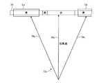
ここで、図5を用いて、図4に示す処理と、予測到着時の信号機の灯色との関係について説明する。図5に示す信号サイクル70は、予測到着時の信号機の灯色を示している。信号サイクル70は、灯色が青から黄に切り替わり、黄から赤に切り替わり、赤から青に切り替わる。また、目標車速制御部20aは、信号サイクル70の通過領域Ea、Ebは、信号の灯色が青で、かつ、灯色が青から赤に切り替わるまでの残り時間が所定時間以上であり、灯色が青になってからの時間が所定時間以上である時間領域である。つまり、目標車速制御部20aは、灯色が青である時間帯のうち、初期と終期の所定時間を除いた時間耐を通過領域Ea、Ebに設定している。なお、信号サイクル70は、時間の経過とともに左から右に向けて進むが、図4に示す処理と、予測到着時の信号機の灯色との関係を模式的に示しているため時間軸が一定ではない。  Here, the relationship between the process shown in FIG. 4 and the color of the traffic light at the time of predicted arrival will be described with reference to FIG. Asignal cycle 70 shown in FIG. 5 indicates the color of the traffic light at the time of predicted arrival. In thesignal cycle 70, the lamp color is switched from blue to yellow, from yellow to red, and from red to blue. Further, the target vehiclespeed control unit 20a indicates that the passage areas Ea and Eb of thesignal cycle 70 have a signal lamp color of blue and the remaining time until the lamp color changes from blue to red is a predetermined time or more. This is a time region in which the time after the color turns blue is a predetermined time or more. That is, the target vehiclespeed control unit 20a sets the time resistance excluding the initial and final predetermined times in the time zone in which the lamp color is blue in the passage areas Ea and Eb. Thesignal cycle 70 progresses from left to right as time elapses, but the time axis is constant because it schematically shows the relationship between the processing shown in FIG. 4 and the lamp color of the traffic light at the predicted arrival time. is not.

また、図5に示すパターン72a、パターン72bは、それぞれある時点において判定を行った場合の算出結果である。パターン72aは、現車速で走行した場合の予測到着時が矢印74aに示す線となり、予測到着時の信号状態が矢印74aの先にある信号状態Sとなる。パターン72aは、現車速から加速度Gaで加速して走行した場合の予測到着時が矢印76aに示す線となり、予測到着時の信号状態が矢印76aの先にある信号状態Saとなる。パターン72aは、現車速から減速度Gbで減速して走行した場合の予測到着時が矢印78aに示す線となり、予測到着時の信号状態が矢印78aの先にある信号状態Sbとなる。同様に、パターン72bは、現車速で走行した場合の予測到着時が矢印74bに示す線となり、予測到着時の信号状態が矢印74bの先にある信号状態Sとなる。パターン72bは、現車速から加速度Gaで加速して走行した場合の予測到着時が矢印76bに示す線となり、予測到着時の信号状態が矢印76bの先にある信号状態Saとなる。パターン72bは、現車速から減速度Gbで減速して走行した場合の予測到着時が矢印78bに示す線となり、予測到着時の信号状態が矢印78bの先にある信号状態Sbとなる。  Further, thepatterns 72a and 72b shown in FIG. 5 are calculation results when the determination is performed at a certain time point. In thepattern 72a, the predicted arrival time when traveling at the current vehicle speed is a line indicated by anarrow 74a, and the signal state at the predicted arrival time is the signal state S ahead of thearrow 74a. In thepattern 72a, the predicted arrival time when traveling at an acceleration Ga from the current vehicle speed is a line indicated by anarrow 76a, and the signal state at the predicted arrival is a signal state Sa ahead of thearrow 76a. In thepattern 72a, the predicted arrival time when traveling at a deceleration Gb from the current vehicle speed is a line indicated by anarrow 78a, and the signal state at the predicted arrival is a signal state Sb ahead of thearrow 78a. Similarly, in thepattern 72b, the predicted arrival time when traveling at the current vehicle speed is a line indicated by anarrow 74b, and the signal state at the predicted arrival time is the signal state S ahead of thearrow 74b. In thepattern 72b, the predicted arrival time when traveling at an acceleration Ga from the current vehicle speed is a line indicated by anarrow 76b, and the signal state at the predicted arrival is a signal state Sa ahead of thearrow 76b. In thepattern 72b, the predicted arrival time when the vehicle decelerates from the current vehicle speed at the deceleration Gb is a line indicated by anarrow 78b, and the signal state at the predicted arrival is a signal state Sb ahead of thearrow 78b.

目標車速制御部20aは、図4に示すステップS14、S16、S18、S22の処理で通過停止判定を行う。例えば、目標車速制御部20aは、パターン72aの時点で判定を行った場合、信号状態SaからSの一部の領域80が、通過領域Eaと重なる。これにより、目標車速制御部20aは、ステップS18でYesと判定し、領域80に対応する速度領域を目標車速域として算出する。また、目標車速制御部20aは、パターン72bの時点で判定を行った場合、信号状態SaからSの間が、通過領域Ea、Ebのいずれとも重ならず、信号状態SからSbの一部の領域82が、通過領域Ebと重なる。これにより、目標車速制御部20aは、ステップS18でNo、ステップS22でYesと判定し、領域82に対応する速度領域を目標車速域として算出する。  The target vehiclespeed control unit 20a performs the passage stop determination in the processes of steps S14, S16, S18, and S22 shown in FIG. For example, when the target vehiclespeed control unit 20a performs the determination at the time of thepattern 72a, a part of theregion 80 of the signal states Sa to S overlaps the passage region Ea. Thereby, the target vehiclespeed control unit 20a determines Yes in step S18, and calculates the speed region corresponding to theregion 80 as the target vehicle speed region. In addition, when the target vehiclespeed control unit 20a makes the determination at the time of thepattern 72b, the signal state Sa to S does not overlap with any of the passing areas Ea and Eb, and a part of the signal state S to Sb. Theregion 82 overlaps with the passage region Eb. Thereby, the target vehiclespeed control unit 20a determines No in step S18, Yes in step S22, and calculates the speed region corresponding to theregion 82 as the target vehicle speed region.

図4に戻り、フローチャートの説明を続ける。目標車速制御部20aは、ステップS20、ステップS24、ステップS26の処理を行ったら、ステップS28として、支援表示を実行する。ここで、目標車速制御部20aは、ステップS20、ステップS24の処理を行った場合、ステップS28の支援表示として通過支援表示を行い、ステップS28の処理を行った場合、ステップS28の支援表示として停止支援表示を行う。  Returning to FIG. 4, the description of the flowchart will be continued. The target vehiclespeed control part 20a will perform a support display as step S28, if the process of step S20, step S24, and step S26 is performed. Here, the target vehiclespeed control unit 20a performs the passage support display as the support display of step S28 when the processes of step S20 and step S24 are performed, and stops as the support display of step S28 when the process of step S28 is performed. Display support.

目標車速制御部20aは、通過支援表示を行う場合、対象の信号機を通過できる速度範囲、つまりステップS20、ステップS24で決定した目標車速域を速度表示領域48に表示する。例えば、目標車速制御部20aは、図6に示す速度表示領域48aを表示する。速度表示領域48aは、目盛り表示部50の目標車速域と重なる速度範囲に目印60を表示している。ここで、本実施形態では、目標車速域が30km/hから50km/hであるため、速度表示領域48aは、目印60を30km/hから50km/hの速度域に表示する。なお、速度表示領域48aは、目盛り表示部50を液晶表示装置に画像で表示している場合、当該液晶表示装置に表示する画像として目印60の画像を重ねればよい。また、速度表示領域48aは、目盛り表示部50がインク等で記入されている場合、目盛り表示部50の目盛りの表示部分に発光部を配置し、目標車速域の発光部を点灯させることで目印60を表示してもよい。このように、目標車速制御部20aは、決定した目標車速域を目印60として目盛り表示部50に重ねて表示することで、利用者に決定した目標車速域を認識させることができる。目標車速制御部20aは、ステップS28に示す処理を行ったら、ステップS30に進む。  The target vehiclespeed control unit 20a displays the speed range in which the target traffic signal can pass, that is, the target vehicle speed range determined in step S20 and step S24, in thespeed display area 48 when performing the passage support display. For example, the target vehiclespeed control unit 20a displays aspeed display area 48a shown in FIG. Thespeed display area 48 a displays amark 60 in a speed range that overlaps the target vehicle speed range of thescale display unit 50. Here, in the present embodiment, since the target vehicle speed range is 30 km / h to 50 km / h, thespeed display area 48a displays themark 60 in the speed range from 30 km / h to 50 km / h. When thescale display unit 50 is displayed as an image on the liquid crystal display device, thespeed display area 48a may be superimposed on the image of themark 60 as an image to be displayed on the liquid crystal display device. In addition, when thescale display unit 50 is filled with ink or the like, thespeed display area 48a is arranged by placing a light emitting unit on the scale display part of thescale display unit 50 and turning on the light emitting unit in the target vehicle speed range. 60 may be displayed. In this manner, the target vehiclespeed control unit 20a can display the determined target vehicle speed range as themark 60 on thescale display unit 50 so that the user can recognize the determined target vehicle speed range. When the target vehiclespeed control unit 20a performs the process shown in step S28, the process proceeds to step S30.

目標車速制御部20aは、停止支援表示を行う場合、当該信号機地点で停止を推奨する速度範囲、つまりステップS26で決定した目標車速域を速度表示領域48に表示する。ここで、本実施形態では、ステップS26で設定したとおり、目標車速域として0km/h付近の速度域を表示する。例えば、目標車速制御部20aは、図7に示す速度表示領域48bを表示する。速度表示領域48bは、目盛り表示部50の目標車速域と重なる速度範囲に目印62を表示している。ここで、停止支援表示は、目標車速域が0km/h付近の速度域(0km/hを含む速度域、本実施形態では、0km/hから10km/h)であるため、速度表示領域48bは、目印62を0km/h付近の速度域に表示する。このように、目標車速制御部20aは、決定した目標車速域を目印62として目盛り表示部50に重ねて表示することで、利用者に決定した目標車速域を認識させることができる。これにより、ステップS22では利用者に車両10を停止させることを推奨していることを認識させることができる。目標車速制御部20aは、ステップS28に示す処理を行ったら、ステップS30に進む。  When the target vehiclespeed control unit 20a performs the stop support display, the target vehiclespeed control unit 20a displays in thespeed display region 48 the speed range recommended to stop at the traffic light point, that is, the target vehicle speed range determined in step S26. Here, in this embodiment, as set in step S26, a speed range near 0 km / h is displayed as the target vehicle speed range. For example, the target vehiclespeed control unit 20a displays aspeed display area 48b shown in FIG. Thespeed display area 48 b displays amark 62 in a speed range that overlaps the target vehicle speed range of thescale display unit 50. Here, since the stop support display is a speed range where the target vehicle speed range is near 0 km / h (speed range including 0 km / h, in this embodiment, from 0 km / h to 10 km / h), thespeed display area 48b is Themark 62 is displayed in the speed range near 0 km / h. As described above, the target vehiclespeed control unit 20a can display the determined target vehicle speed range as themark 62 on thescale display unit 50 so that the user can recognize the determined target vehicle speed range. Thereby, it can be made to recognize that the user recommends stopping thevehicle 10 in step S22. When the target vehiclespeed control unit 20a performs the process shown in step S28, the process proceeds to step S30.

目標車速制御部20aは、ステップS28の処理を行ったら、ステップS30として表示終了条件が成立しているかを判定する。ここで、表示終了条件とは、予め設定した目標車速域の表示終了の条件であり、例えば、車両と交差点(対象の信号機)との距離が一定以下となった場合、車速が一定の範囲外となった場合、目標車速域を表示してから一定時間が経過した場合等である。目標車速制御部20aは、ステップS30で条件が成立していない(No)と判定した場合、ステップS12に進み、上述した処理を繰り返す。つまり目標車速域を再度算出して目標車速域を再表示させる。目標車速制御部20aは、ステップS30で条件が成立した(Yes)と判定した場合、本処理を終了する。  The target vehiclespeed control part 20a will determine whether display end conditions are satisfied as step S30, if the process of step S28 is performed. Here, the display end condition is a display end condition of the target vehicle speed range set in advance. For example, when the distance between the vehicle and the intersection (target traffic signal) is less than a certain range, the vehicle speed is out of the certain range. Or a certain time has elapsed since the target vehicle speed range was displayed. If the target vehiclespeed control unit 20a determines in step S30 that the condition is not satisfied (No), the target vehiclespeed control unit 20a proceeds to step S12 and repeats the above-described processing. That is, the target vehicle speed range is calculated again and the target vehicle speed range is displayed again. If the target vehiclespeed control unit 20a determines that the condition is satisfied (Yes) in Step S30, the target vehiclespeed control unit 20a ends this process.

運転支援装置19(およびこれを有する車両10、運転支援システム1)は、このように、図4に示すステップS14、S16、S18、S22の処理で通過停止判定処理を行う。具体的には、運転支援装置19は、図5に示すように、判定時点において、現車速で走行した場合、現車速から加速度Gaで加速して走行した場合、現車速から減速度Gbで減速して走行した場合のそれぞれの場合についての信号状態S、Sa、Sbを算出することでパターン72a、72bを算出する。運転支援装置19は、パターン72a、72bを算出することで、現車速から加速度Gaで走行し、設定されている条件の中で最も速く信号機地点に到達する場合から、現車速から減速度Gbで走行し、設定されている条件の中で最も遅く信号機地点に到達する場合までの時間範囲を検出することができる。また、運転支援装置19は、パターン72a、72bと通過領域Ea、Ebとが重なるかを判定することで、設定した条件内で信号機地点に到達させた場合に、信号状態が青である場合があるかを判定することができる。  In this way, the driving support device 19 (and thevehicle 10 having the same, the driving support system 1) performs the passage stop determination process in the processes of steps S14, S16, S18, and S22 shown in FIG. Specifically, as shown in FIG. 5, when driving at the current vehicle speed, the drivingsupport device 19 accelerates at the acceleration Ga from the current vehicle speed, and decelerates at the deceleration Gb from the current vehicle speed. Then, thepatterns 72a and 72b are calculated by calculating the signal states S, Sa, and Sb for each case when the vehicle travels. The drivingsupport device 19 calculates thepatterns 72a and 72b so that the vehicle travels at the acceleration Ga from the current vehicle speed, and from the current vehicle speed at the deceleration Gb from the time when it reaches the traffic light point the fastest in the set conditions. It is possible to detect the time range until the vehicle travels and arrives at the traffic light point the latest among the set conditions. Further, when the drivingsupport device 19 determines whether thepatterns 72a and 72b and the passage areas Ea and Eb overlap with each other to reach the traffic light point within the set conditions, the signal state may be blue. It can be determined whether there is.

運転支援装置19は、図4および図5に示す処理に基づいて通過停止判定を行うことで、現車速を基準として設定した加速または減速で信号機地点の到着時に、信号機地点の到着時に灯色が青となる場合、通過支援を行うことができる。これにより、運転支援装置19は、現車速に過度な加速、減速が必要な場合は、通過できないと判定するため、許容加速度Ga、許容減速度Gbを超える速度変化が必要となる通過判定の目標速度域を、速度表示領域48に表示する目標車速域として表示させない。これにより、運転支援装置19は、急激な加速、減速が必要な目標車速域が表示されることを抑制することができ、運転者に違和感やストレスを与える恐れの低い、目標車速域を表示させることができる。また、運転者は、適切な範囲の加速と減速で目標車速域での走行が可能となるため、運転しやすい状態を維持しつつ、好適な条件(本実施形態では、赤信号での停止を少なくしつつ)車両10を走行させることができる。なお、運転支援装置19は、停止判定を行った場合は、信号機地点よりも前で車両を停止させるため、許容減速度Gbを超える減速度の目標速度域を表示させることがある。  The drivingsupport device 19 performs the passage stop determination based on the processing shown in FIGS. 4 and 5, so that the color of the light is reached when the traffic light arrives at the traffic light spot at the acceleration or deceleration set based on the current vehicle speed. If it turns blue, you can help pass. As a result, the drivingsupport device 19 determines that the vehicle cannot pass if excessive acceleration or deceleration is required for the current vehicle speed, and therefore a target for determination of passage that requires a change in speed exceeding the allowable acceleration Ga and the allowable deceleration Gb. The speed range is not displayed as the target vehicle speed range displayed in thespeed display area 48. As a result, the drivingsupport device 19 can suppress the display of the target vehicle speed range that requires rapid acceleration and deceleration, and displays the target vehicle speed range that is less likely to cause discomfort and stress to the driver. be able to. In addition, since the driver can travel in the target vehicle speed range with an appropriate range of acceleration and deceleration, the driver can easily stop while maintaining a suitable condition (in this embodiment, stop with a red signal). Thevehicle 10 can be made to travel (with less). Note that when the stop determination is made, the drivingsupport device 19 may display a target speed range of deceleration exceeding the allowable deceleration Gb in order to stop the vehicle before the traffic light point.

また、所定の加速や減速で信号機を通過できる場合に、好適な通過支援を行うことができ、運転者により好適な目標速度域を表示させることができる。また、運転者に所定の加速、減速で通過できたのではないかという印象を与えることを防止することができ、運転者に不信感を与えにくい運転支援を行うことができる。  In addition, when the traffic light can be passed through at a predetermined acceleration or deceleration, suitable passing assistance can be performed, and a suitable target speed range can be displayed by the driver. In addition, it is possible to prevent the driver from giving an impression that he / she could pass at a predetermined acceleration and deceleration, and to perform driving support that hardly causes distrust to the driver.

運転支援装置19は、このように算出したパターン72a、72bと通過領域Ea、Ebとの関係に基づいて目標車速域を算出する。つまり、運転支援装置19は、現車速に基づいて設定した加速度、減速度に基づいて目標車速域を決定し、表示させる。つまり、運転支援装置19は、速度表示領域48に表示する目標車速域として、現車速から過度な加速、減速が必要な速度を目標車速域に表示しない。これにより、運転支援装置19は、急激な加速、減速が必要な目標車速域が表示されることをより確実に抑制することができ、運転者に違和感やストレスを与える恐れの低い、目標車速域を表示させることができる。また、運転者は、適切な範囲の加速と減速で目標車速域での走行が可能となるため、運転しやすい状態を維持しつつ、好適な条件(本実施形態では、赤信号での停止を少なくしつつ)車両10を走行させることができる。  The drivingsupport device 19 calculates the target vehicle speed range based on the relationship between thepatterns 72a and 72b calculated as described above and the passing areas Ea and Eb. That is, the drivingsupport device 19 determines and displays the target vehicle speed range based on the acceleration and deceleration set based on the current vehicle speed. That is, the drivingassistance device 19 does not display a speed that requires excessive acceleration or deceleration from the current vehicle speed as the target vehicle speed range to be displayed in thespeed display area 48 in the target vehicle speed range. As a result, the drivingassistance device 19 can more reliably suppress the display of the target vehicle speed range that requires rapid acceleration and deceleration, and the target vehicle speed range that is less likely to cause discomfort and stress to the driver. Can be displayed. In addition, since the driver can travel in the target vehicle speed range with an appropriate range of acceleration and deceleration, the driver can easily stop while maintaining a suitable condition (in this embodiment, stop with a red signal). Thevehicle 10 can be made to travel (with less).

運転支援装置19は、現車速を基準として許容加速度Gaで走行した場合、許容減速度Gbで走行した場合の両方について信号状態を算出し、パターンを形成して判定を行うことが好ましいが、いずれか一方でもよい。つまり、運転支援装置19は、現車速で走行した場合の信号状態Sと現車速を基準として許容加速度Gaで走行した場合との信号状態Saを算出して、信号状態Saと信号状態Sとの間と通過領域との関係に基づいて、通過判定を行うようにしてもよい。同様に運転支援装置19は、現車速で走行した場合の信号状態Sと現車速を基準として許容減速度Gbで走行した場合との信号状態Sbを算出して、信号状態Sと信号状態Sbとの間と通過領域との関係に基づいて、通過判定を行うようにしてもよい。  The drivingsupport device 19 preferably calculates the signal state for both the case where the vehicle travels with the allowable acceleration Ga with respect to the current vehicle speed and the case where the vehicle travels with the allowable deceleration Gb, and forms a pattern to make the determination. Either one is fine. That is, the drivingsupport device 19 calculates the signal state Sa when traveling at the current vehicle speed and the signal state Sa when traveling at the allowable acceleration Ga with reference to the current vehicle speed, and the signal state Sa and the signal state S are calculated. The passage determination may be performed based on the relationship between the distance and the passage area. Similarly, the drivingsupport device 19 calculates the signal state S when the vehicle travels at the current vehicle speed and the signal state Sb when the vehicle travels at the allowable deceleration Gb based on the current vehicle speed. Pass determination may be performed based on the relationship between the interval and the passage area.

ここで、図8は、運転支援装置の処理の一例を説明するための説明図である。図8に示す信号サイクル70は、図5に示す信号サイクル70と同じである。目標車速制御部20aは、灯色が青である時間帯のうち、初期と終期の所定時間を除いた時間耐を通過領域Ea、Ebに設定している。図8に示すパターン72cも、ある時点において判定を行った場合の算出結果である。パターン72cは、現車速で走行した場合の予測到着時が矢印74cに示す線となり、現車速から加速度Gaで加速して走行した場合の予測到着時が矢印76cに示す線となり、現車速から減速度Gbで減速して走行した場合の予測到着時が矢印78cに示す線となる。  Here, FIG. 8 is an explanatory diagram for explaining an example of processing of the driving support device. Thesignal cycle 70 shown in FIG. 8 is the same as thesignal cycle 70 shown in FIG. The target vehiclespeed control unit 20a sets the time tolerance excluding the initial and final predetermined times in the time zone in which the lamp color is blue in the passage areas Ea and Eb. Apattern 72c shown in FIG. 8 is also a calculation result when the determination is performed at a certain time point. In thepattern 72c, the predicted arrival time when traveling at the current vehicle speed is a line indicated by anarrow 74c, and the predicted arrival time when traveling at an acceleration Ga from the current vehicle speed is indicated by anarrow 76c, which is reduced from the current vehicle speed. The predicted arrival time when the vehicle decelerates at the speed Gb is a line indicated by anarrow 78c.

運転支援装置19は、図8に示すパターン72cで判定を行う場合、所定の加速度で加速した場合の信号状態が通過領域Eaと重なり、所定の減速度で減速した場合の信号状態が通過領域Ebと重なる。この場合、運転支援装置19は、図4に示す処理を行なうと、所定の加速度で加速した場合の信号状態と通過領域との比較を先に実行するため、通過領域Eaと重なっている領域に基づいて目標車速域を算出する。このように、運転支援装置19は、所定の加速度で加速した場合の信号状態と通過領域との比較を先に実行することで、より早く当該信号機を通過することが可能となる。  When the drivingsupport device 19 performs the determination using thepattern 72c shown in FIG. 8, the signal state when accelerating at a predetermined acceleration overlaps the passage area Ea, and the signal state when decelerating at a predetermined deceleration is the passage area Eb. And overlap. In this case, when the process shown in FIG. 4 is performed, the drivingsupport device 19 first performs a comparison between the signal state and the passage area when accelerating at a predetermined acceleration. Based on this, a target vehicle speed range is calculated. As described above, the drivingsupport device 19 can pass through the traffic signal earlier by executing the comparison between the signal state and the passage area when accelerating at a predetermined acceleration.

なお、運転支援装置19は、図4に示す処理のステップS18とステップS22の順序を入れ替えてもよい。また、運転支援装置19は、図4に示す処理のステップS18とステップS22の順序を各種条件に基づいて決定してもよい。例えば、運転支援装置19は、車載カメラ34や、ミリ波レーダ等で先方の車両の有無を判定し、前方の近接した位置に車両がある場合、ステップS22の処理をステップS18よりも先に実行し、前方の近接した位置に車両がない場合、ステップS18の処理をステップS22よりも先に実行するようにしてもよい。また、運転支援装置19は、ステップS20、ステップS24の目標車速域の算出処理を両方行い、現車速により近い目標車速域を含む目標車速域を算出結果として表示させてもよい。またステップS20、ステップS24で算出した両方の目標車速域を表示させてもよい。  In addition, the drivingassistance device 19 may exchange the order of step S18 and step S22 of the process illustrated in FIG. Moreover, the drivingassistance apparatus 19 may determine the order of step S18 and step S22 of the process shown in FIG. 4 based on various conditions. For example, the drivingsupport device 19 determines the presence or absence of a vehicle ahead by using the in-vehicle camera 34, millimeter wave radar, or the like, and if the vehicle is in a close position ahead, executes the process of step S22 before step S18. And when there is no vehicle in the position which approached ahead, you may make it perform the process of step S18 ahead of step S22. Further, the drivingsupport device 19 may perform both of the target vehicle speed range calculation processes in Step S20 and Step S24 and display the target vehicle speed range including the target vehicle speed range closer to the current vehicle speed as the calculation result. Further, both target vehicle speed ranges calculated in step S20 and step S24 may be displayed.

運転支援装置19は、図5に示すように、通過領域Ea、Ebを信号機が通過可能な表示ではない(例えば、灯色が赤)状態から前記信号機が通過可能な表示である(例えば、灯色が青)状態に切り替わって閾値時間経過した後から、信号機が通過可能な表示である(例えば、灯色が青)状態から信号機が通過可能な表示ではない(例えば、灯色が赤)状態に切り替わるよりも閾値時間前までの間とし、当該通過領域Ea、Ebの間に信号機が配置された信号機地点を車両が通過できる速度域を目標車速域として算出する。  As shown in FIG. 5, the drivingsupport device 19 is a display that allows the traffic light to pass from a state where the traffic light is not allowed to pass through the passage areas Ea and Eb (for example, the lamp color is red) (for example, a light lamp). After the threshold time elapses after the color is switched to the blue state, the display allows the traffic light to pass (for example, the light color is blue) and the display does not allow the traffic light to pass (for example, the light color is red). The speed range in which the vehicle can pass through the traffic light point where the traffic light is arranged between the passage areas Ea and Eb is calculated as the target vehicle speed area.

このように、運転支援装置19は、目標車速域を、灯色が青から赤に切り替わるまでの残り時間が所定時間以上となる範囲とすることで、走行時に目標車速以下に減速してしまい信号機に到達するまでに時間が多少かかってしまった場合でも、灯色が赤になる前に信号機を通過することができる。運転支援装置19は、目標車速域を、灯色が青になってからの時間が所定時間以上となる範囲とすることで、信号機に到達する前に一定の余裕がある距離で、信号機の灯色が赤から青に切り替わる。これにより、灯色が赤のままで変わらない状態で信号機に接近することを抑制でき、運転者に対して灯色が切り替わるか、減速するべきかという不安を与えることを抑制することができ、運転者に違和感を与えることを抑制できる。  In this way, the drivingsupport device 19 sets the target vehicle speed range to a range in which the remaining time until the lamp color changes from blue to red is equal to or longer than a predetermined time. Even if it takes some time to reach, you can pass through the traffic light before the light turns red. The drivingsupport device 19 sets the target vehicle speed range to a range in which the time after the color of the light turns blue is equal to or longer than a predetermined time, so that the light of the traffic light is at a certain distance before reaching the traffic light. The color changes from red to blue. Thereby, it is possible to suppress the approach to the traffic light in a state where the lamp color remains red and does not change, and it is possible to suppress giving the driver anxiety about whether the lamp color is switched or decelerated, Giving the driver a sense of incongruity can be suppressed.

また、運転支援装置19は、上述した目標車速域の算出の閾値時間(所定時間)、つまり、予測到着時の灯色が青のうち、目標車速域の算出の対象としない境界の時間を、位置算出部で算出した車両と信号機が配置された信号機地点との距離に応じて調整、決定することが好ましい。これにより、距離に応じた処理を好適に実行することができる。  Further, the drivingsupport device 19 calculates the above-described threshold time (predetermined time) for calculating the target vehicle speed range, that is, the boundary time that is not subject to calculation of the target vehicle speed range when the predicted arrival color is blue. It is preferable to adjust and determine according to the distance between the vehicle calculated by the position calculation unit and the traffic light point where the traffic light is arranged. Thereby, the process according to distance can be performed suitably.

また、運転支援装置19は、上述した通過停止判定の許容加速度Ga、許容減速度Gbを、位置算出部で算出した車両と信号機が配置された信号機地点との距離に応じて調整、決定することが好ましい。これにより、運転支援装置19は、車両と信号機地点との距離に対応して通過停止判定の基準を変更することができ、より適切な通過停止判定を行うことができる。具体的には、車両と信号機が配置された信号機地点との距離が長いほど許容加速度Ga、許容減速度Gbを小さくし、位置算出部で算出した車両と信号機が配置された信号機地点との距離が短いほど許容加速度Ga、許容減速度Gbを大きくすることが好ましい。これにより、加速が大きくなりすぎ、実際に実現できない目標車速を算出してしまう恐れを低減することができる。  Further, the drivingsupport device 19 adjusts and determines the allowable acceleration Ga and allowable deceleration Gb for the above-described passage stop determination according to the distance between the vehicle calculated by the position calculation unit and the traffic light point where the traffic light is arranged. Is preferred. Thereby, the drivingassistance device 19 can change the reference for the passage stop determination in accordance with the distance between the vehicle and the traffic light point, and can perform a more appropriate passage stop determination. Specifically, the longer the distance between the vehicle and the traffic light point where the traffic light is located, the smaller the allowable acceleration Ga and the allowable deceleration Gb, and the distance between the vehicle calculated by the position calculation unit and the traffic light point where the traffic light is located. It is preferable to increase the allowable acceleration Ga and the allowable deceleration Gb as the length is shorter. As a result, it is possible to reduce the possibility of calculating a target vehicle speed that is excessively accelerated and cannot actually be realized.

また、運転支援装置19は、上述した通過停止判定の許容加速度Ga、許容減速度Gbを、現在の信号機の灯色に応じて調整、決定することも好ましい。運転支援装置19は、例えば現在の信号機の灯色が赤の場合は、許容加速度Gaをより小さい値に変更し、許容減速度Gbをより大きい値に変更してもよい。運転支援装置19は、例えば現在の信号機の灯色が青の場合は、許容加速度Gaをより大きい値に変更し、許容減速度Gbをより小さい値に変更してもよい。これにより、運転者は、前方にある信号機の灯色が赤の場合は、パターンと次に青が点灯された際の通過領域とが重なりやすくなり、停止せずに信号機を通過する速度をより確実に算出することができる。運転者は、前方にある信号機の灯色が青の場合は、パターンと現在点灯している青の信号状態を含む通過領域とが重なりやすくなり、停止せずに信号機を通過する速度をより確実に算出することができる。なお、許容加速度Gaの基準の値としては、0.1G、許容減速度Gbの基準の値としては0.3G(−0.3G)が例示される。  In addition, it is preferable that the drivingsupport device 19 adjusts and determines the allowable acceleration Ga and the allowable deceleration Gb for the above-described passage stop determination according to the current light color of the traffic light. For example, when the light color of the current traffic light is red, the drivingsupport device 19 may change the allowable acceleration Ga to a smaller value and change the allowable deceleration Gb to a larger value. For example, when the current traffic light is blue, the drivingsupport device 19 may change the allowable acceleration Ga to a larger value and change the allowable deceleration Gb to a smaller value. As a result, when the traffic light in front of the traffic light is red, the driver tends to overlap the pattern and the passing area when blue is lit next, and the speed of passing through the traffic light without stopping is increased. It is possible to calculate with certainty. If the traffic light in front of the traffic light is blue, the driver is more likely to overlap the pattern and the passing area that includes the blue traffic light that is currently lit. Can be calculated. The reference value of the allowable acceleration Ga is exemplified by 0.1 G, and the reference value of the allowable deceleration Gb is exemplified by 0.3 G (−0.3 G).

本実施形態の運転支援装置19は、停止支援として、ステップS26で決定した目標車速域を表示したが、これに限定されない。運転支援装置19は、通過支援が可能ではない場合、目標車速域を表示しないようにしてもよい。  The drivingassistance device 19 of the present embodiment displays the target vehicle speed range determined in step S26 as stop assistance, but is not limited to this. The drivingassistance device 19 may not display the target vehicle speed range when the passage assistance is not possible.

また、上記実施形態の運転支援装置19は、加速時から減速時までの信号状態と通過領域とが重なる領域に基づいて目標車速域を決定したが、目標速度域を種々の基準で決定、加工することができる。図9および図10は、それぞれ、運転支援装置の処理の一例を説明するための説明図である。図9は、基本的に図5の信号サイクル70とパターン72aとを拡大して示している。運転支援装置19は、図4に示すフローチャートでは、矢印76aと重なる目印92の時点、つまり信号状態Saに基づいて、目標速度域の上限速度を決定する。これにより、許容加速度で到達することができる速度を目標速度域の上限速度とすることができる。ここで、運転支援装置19は、目標速度域の上限速度をパターン72aと重なっている通過領域Eaの最も早い時点、つまり目印94の時点に基づいて算出してもよい。この場合、目標車速域の上限速度は、大きくなるため、別途閾値を設けてもよい。例えば、運転支援装置19は、現車速+α、つまり現車速よりも一定速度速い速度を目標車速域の上限速度としてもよい。運転支援装置19は、現車速+αを上限速度とすることで、車速を目標車速域とするために必要な加速が大きくなることを抑制することができる。これにより、車両10および運転支援装置19は、運転者に違和感やストレスを与える恐れのより低い目標車速域を表示させることができる。  Further, the drivingsupport device 19 of the above embodiment determines the target vehicle speed range based on the region where the signal state from the acceleration time to the deceleration time and the passing region overlap, but determines and processes the target speed region based on various criteria. can do. FIG. 9 and FIG. 10 are explanatory diagrams for explaining an example of processing of the driving support device. FIG. 9 basically shows thesignal cycle 70 and thepattern 72a of FIG. 5 in an enlarged manner. In the flowchart shown in FIG. 4, the drivingsupport device 19 determines the upper limit speed of the target speed range based on the time of themark 92 that overlaps thearrow 76 a, that is, the signal state Sa. Thus, the speed that can be reached with the allowable acceleration can be set as the upper limit speed of the target speed range. Here, the drivingsupport device 19 may calculate the upper limit speed of the target speed range based on the earliest time point of the passing area Ea that overlaps thepattern 72a, that is, the time point of themark 94. In this case, since the upper limit speed of the target vehicle speed range increases, a separate threshold value may be provided. For example, the drivingsupport device 19 may set the current vehicle speed + α, that is, a speed that is a constant speed higher than the current vehicle speed, as the upper limit speed of the target vehicle speed range. The drivingsupport device 19 can suppress an increase in acceleration necessary for setting the vehicle speed to the target vehicle speed range by setting the current vehicle speed + α as the upper limit speed. Thereby, thevehicle 10 and the drivingsupport device 19 can display a target vehicle speed range that is less likely to give the driver a sense of discomfort or stress.

運転支援装置19は、目標速度域の上限速度を現車速+α、つまり現車速よりも一定速度速い速度にもこれに限定されない。また、通過支援可能かを判断する基準の速度も以下に説明する目標速度域の上限速度と同様に各種基準を用いることができる。  The drivingsupport device 19 is not limited to the upper limit speed in the target speed range, which is the current vehicle speed + α, that is, a speed that is a constant speed higher than the current vehicle speed. Various standards can be used as the reference speed for determining whether or not the passage support is possible, similarly to the upper limit speed of the target speed range described below.

図10は、基本的に図5の信号サイクル70とパターン72bとを拡大して示している。運転支援装置19は、図4に示すフローチャートでは、矢印78bと重なる目印96の時点、つまり信号状態Sbに基づいて、目標速度域の下限速度を決定する。これにより、許容減速度で到達することができる速度を目標速度域の下限速度とすることができる。ここで、運転支援装置19は、目標速度域の下限速度をパターン72bと重なっている通過領域Ebの最も遅い時点、に基づいて算出してもよい。この場合、目標車速域の下限速度は、小さくなる。このため、下限速度は、上限速度と同様に別途閾値を設けてもよい。  FIG. 10 basically shows thesignal cycle 70 and thepattern 72b of FIG. 5 in an enlarged manner. In the flowchart shown in FIG. 4, the drivingsupport device 19 determines the lower limit speed of the target speed range based on the time point of themark 96 that overlaps thearrow 78b, that is, the signal state Sb. Thereby, the speed that can be reached with the allowable deceleration can be set as the lower limit speed of the target speed range. Here, the drivingassistance device 19 may calculate the lower limit speed of the target speed range based on the latest point in the passing area Eb that overlaps thepattern 72b. In this case, the lower limit speed of the target vehicle speed range becomes small. For this reason, the lower limit speed may be provided with a separate threshold similarly to the upper limit speed.

また、上記実施形態の運転支援装置19は、いずれも現車速を用いて、目標速度域の上限速度を決定したがこれに限定されない。運転支援装置19は、目標速度域の上限速度として、車両が走行している道路(道)の制限車速を用いてもよい。ここで、制限車速は、例えば現在走行している道路の法定速度であり、インフラ通信部38で取得するインフラ情報や、GPS通信部32で受信したGPS信号で現在位置を検出し地図情報データベース22aに記憶されている現在位置の情報から取得すればよい。運転支援装置19は、制限車速の情報を取得する情報取得部として、インフラ通信部38やGPS通信部32と地図情報データベース22aとの組み合わせを用いることができる。制限車速の情報を取得する情報取得部は、運転支援装置19の他の機能、例えば車載カメラ34を用いてもよい。運転支援装置19は、車載カメラ34で走行中の道路に設置された標識の画像を取得し、当該標識の画像に表示されている法定速度を制限車速として検出してもよい。運転支援装置19は、目標車速域の上限速度として、制限車速を用いることで、目標車速域の表示が制限車速を超えることを抑制することができる。これにより、運転支援装置19は、制限車速以下の速度で目標車速域を表示することができるため、実際には走行してはいけない速度が表示されることを抑制でき、運転者に違和感やストレスを与える恐れのより低い目標車速域を表示させることができる。  Moreover, although the drivingassistance apparatus 19 of the said embodiment all determined the upper limit speed of the target speed area using the present vehicle speed, it is not limited to this. The drivingassistance device 19 may use the vehicle speed limit of the road (road) on which the vehicle is traveling as the upper limit speed of the target speed range. Here, the vehicle speed limit is, for example, the legal speed of the road on which the vehicle is currently traveling, and the map information database 22a is detected by detecting the current position from the infrastructure information acquired by theinfrastructure communication unit 38 or the GPS signal received by theGPS communication unit 32. May be obtained from the information of the current position stored in. The drivingsupport device 19 can use a combination of theinfrastructure communication unit 38, theGPS communication unit 32, and the map information database 22a as an information acquisition unit that acquires information on the limited vehicle speed. The information acquisition unit that acquires information on the limited vehicle speed may use another function of the drivingsupport device 19, for example, the in-vehicle camera 34. The drivingsupport device 19 may acquire an image of a sign installed on the road on which the vehicle is running with the in-vehicle camera 34 and detect the legal speed displayed in the image of the sign as the vehicle speed limit. The drivingsupport device 19 can suppress the display of the target vehicle speed range from exceeding the limit vehicle speed by using the limited vehicle speed as the upper limit speed of the target vehicle speed range. As a result, since the drivingsupport device 19 can display the target vehicle speed range at a speed equal to or lower than the limit vehicle speed, it can suppress the display of a speed that should not be actually traveled, and the driver feels uncomfortable or stressed. It is possible to display a target vehicle speed range that is less likely to give

なお、上記実施形態の運転支援装置19は、現車速と制限車速の両方を用いて目標速度域の上限速度を決定することがより好ましい。つまり、運転支援装置19は、いずれも現車速を用いて、目標速度域の上限速度を決定する場合も目標車速域が制限車速を超えないようにすることが好ましい。これにより、運転支援装置19は、上述の両方の効果を得ることができ、運転者に違和感やストレスを与える恐れのより低い目標車速域を表示させることができる。  In addition, it is more preferable that the drivingsupport device 19 of the above-described embodiment determines the upper limit speed of the target speed range using both the current vehicle speed and the limited vehicle speed. That is, it is preferable that the drivingsupport device 19 prevents the target vehicle speed range from exceeding the limit vehicle speed even when the upper limit speed of the target speed range is determined using the current vehicle speed. Thereby, the drivingassistance device 19 can obtain both of the above-described effects, and can display a target vehicle speed range that is less likely to give the driver a sense of discomfort or stress.

運転支援装置19は、通過支援時に表示する目標車速域と、停止支援時に表示する目標車速域とで、表示する目印の色を異なる色とすることが好ましい。なお、色ではなく模様や、点灯状態等を異なるようにしてもよい。これにより、運転者は、通過支援が表示されているか、停止支援が表示されているかをすぐに把握することができる。  The drivingassistance device 19 preferably uses different colors for the marks to be displayed in the target vehicle speed range displayed at the time of passing assistance and the target vehicle speed range displayed at the time of stop assistance. In addition, you may make it change a pattern, a lighting state, etc. instead of a color. Thereby, the driver can immediately grasp whether the passage assistance is displayed or the stop assistance is displayed.

図11は、運転支援装置の処理の他の例を示すフローチャートである。図12は、運転支援装置の処理の一例を説明するための説明図である。また、上記実施形態の運転支援装置19は、通過判定のパターンの算出時にも車両が走行している道路(道)の制限車速を考慮することが好ましい。ここで、図11に示す処理は、図4に示すステップS16の処理の一部として実行される。図11に示す処理は、信号状態Saの算出時に用いる車速の条件を決定する処理である。  FIG. 11 is a flowchart illustrating another example of processing of the driving support device. FIG. 12 is an explanatory diagram for explaining an example of processing of the driving support device. Moreover, it is preferable that the drivingassistance apparatus 19 of the said embodiment considers the limit vehicle speed of the road (road) on which the vehicle is drive | working also at the time of calculation of the pattern of passage determination. Here, the process shown in FIG. 11 is executed as a part of the process of step S16 shown in FIG. The process shown in FIG. 11 is a process for determining the vehicle speed condition used when calculating the signal state Sa.

運転支援装置19の目標車速制御部20aは、図11に示すように、ステップS40として、現車速<制限車速であるかを判定する。目標車速制御部20aは、ステップS40で現車速<制限車速ではない(No)と判定した場合、ステップS41として、V=制限車速として、本処理を終了する。これにより、目標車速制御部20aは、現車速が制限車速以上である場合、許容加速度Gaを加味せず、制限速度で走行した場合の到達予測時の信号状態を信号状態Saとして算出する。  As shown in FIG. 11, the target vehiclespeed control unit 20a of the drivingsupport device 19 determines whether or not the current vehicle speed is less than the limit vehicle speed as step S40. If the target vehiclespeed control unit 20a determines in step S40 that the current vehicle speed is not less than the limit vehicle speed (No), the process ends in step S41, where V = limit vehicle speed. Thereby, the target vehiclespeed control unit 20a calculates the signal state at the time of arrival prediction when traveling at the speed limit without taking into account the allowable acceleration Ga when the current vehicle speed is equal to or higher than the speed limit vehicle speed as the signal state Sa.

目標車速制御部20aは、ステップS40で現車速<制限車速ではある(Yes)と判定した場合、ステップS42として、加速度Gaで加速した場合に制限車速に到達する地点Daを算出し、ステップS44として、Da<Distであるかを判定する。ここで、Distは、現在位置から信号機地点までの距離である。つまり、目標車速制御部20aは、ステップS44として、加速度Gaで加速した場合に制限車速に到達する地点Daまでの距離が、現在位置から信号機地点までの距離でよりも短いかを判定している。  If the target vehiclespeed control unit 20a determines in step S40 that the current vehicle speed is less than the limited vehicle speed (Yes), the target vehiclespeed control unit 20a calculates a point Da that reaches the limited vehicle speed when accelerating with the acceleration Ga, as step S42, and as step S44. , Da <Dist. Here, Dist is the distance from the current position to the traffic light point. That is, the target vehiclespeed control unit 20a determines in step S44 whether the distance to the point Da that reaches the limit vehicle speed when accelerating at the acceleration Ga is shorter than the distance from the current position to the traffic light point. .

目標車速制御部20aは、ステップS44でDa<Distではある(Yes)と判定した場合、ステップS46としてDa以降はV=制限車速として、本処理を終了する。これにより、目標車速制御部20aは、Da<Distではある場合、図12に示すパターン72dを算出する。パターン72dは、矢印76dに示すように、地点Daまでは加速度Gaで加速し、矢印76eに示すように、地点Da以降は制限速度で走行して信号機地点まで走行した場合の予想到達時の信号状態を信号状態Saとして算出する。また、パターン72dは、現車速で走行した場合の予想到達時の信号状態を信号状態Sとしている。  If the target vehiclespeed control unit 20a determines that Da <Dist is true (Yes) in step S44, the process ends in step S46 with Da = V = restricted vehicle speed after Da. Thereby, the target vehiclespeed control unit 20a calculates the pattern 72d shown in FIG. 12 when Da <Dist. As shown by anarrow 76d, the pattern 72d accelerates at an acceleration Ga up to a point Da, and as indicated by anarrow 76e, the signal at the time of expected arrival when the vehicle travels at a speed limit and travels to a traffic light point after the point Da. The state is calculated as the signal state Sa. In the pattern 72d, the signal state S is the signal state when the vehicle arrives at the expected arrival time when traveling at the current vehicle speed.

目標車速制御部20aは、ステップS44でDa<Distはない(No)と判定した場合、ステップS48としてV=V0+Ga×tとして、本処理を終了する。これにより、目標車速制御部20aは、Da<Distではない場合、信号機地点まで許容加速度Gaで加速して走行した場合の到達予測時の信号状態を信号状態Saとして算出する。  If the target vehiclespeed control unit 20a determines that Da <Dist does not exist (No) in step S44, the process ends in step S48 with V = V0 + Ga × t. Thereby, the target vehiclespeed control part 20a calculates the signal state at the time of the arrival prediction at the time of driving | running | working with acceleration with the allowable acceleration Ga to a traffic light point, when Da <Dist is not carried out as signal state Sa.

運転支援装置19は、図11および図12に示すように、制限車速を加味して信号状態Saを算出し、算出した信号状態Saと現車速を用いて算出した信号状態Sとを用いて、通過停止判定を行うことで、規則上走行できない車速範囲の目標車速域が表示されることを抑制することができる。これにより、運転者に不要なストレスを与えることを抑制することができる。  As shown in FIGS. 11 and 12, the drivingsupport device 19 calculates the signal state Sa in consideration of the limited vehicle speed, and uses the calculated signal state Sa and the signal state S calculated using the current vehicle speed, By performing the passage stop determination, it is possible to suppress the display of the target vehicle speed range in the vehicle speed range where the vehicle cannot travel on a regular basis. Thereby, it can suppress giving a driver unnecessary stress.

また、上記実施形態の運転支援装置19は、表示装置42の速度表示領域48に表示する速度表示をアナログメータとしたが、これに限定されない。上記実施形態の運転支援装置19は、表示装置42の速度表示領域48に表示する速度表示をデジタルメータとしてもよい。運転支援装置19は、数字で速度を表示する表示機構である速度表示領域に、第1領域と第2領域とを有する。第1領域は、現車速を表示する領域である。第2領域は、第1領域の画面上側の領域であり、目標車速域を表示する領域である。このように、運転支援装置19は、表示装置42の速度表示領域をデジタルメータで表示しても、上記と同様の効果を得ることができる。ここで、運転支援装置19は、速度表示領域の第1領域に表示させる現車速と、第2領域に表示させる目標車速域と、を異なる色および異なる大きさの少なくとも一方で表示させることが好ましい。これにより、運転支援装置19は、運転者が現車速と目標車速域とを混同する恐れを抑制することができる。  Moreover, although the drivingassistance apparatus 19 of the said embodiment used the analog meter for the speed display displayed on thespeed display area 48 of thedisplay apparatus 42, it is not limited to this. The drivingsupport device 19 of the above embodiment may use a digital meter for the speed display displayed in thespeed display area 48 of thedisplay device 42. The drivingsupport device 19 includes a first area and a second area in a speed display area that is a display mechanism that displays a speed with numbers. The first area is an area for displaying the current vehicle speed. The second area is an area on the upper side of the screen of the first area, and is an area for displaying the target vehicle speed range. Thus, even if the drivingassistance device 19 displays the speed display area of thedisplay device 42 with the digital meter, the same effect as described above can be obtained. Here, it is preferable that the drivingassistance device 19 displays the current vehicle speed displayed in the first area of the speed display area and the target vehicle speed area displayed in the second area in at least one of different colors and different sizes. . Thereby, the drivingassistance device 19 can suppress the possibility that the driver will confuse the current vehicle speed with the target vehicle speed range.

運転支援装置19は、現車速と、加速度(許容加速度)Gaと、減速度(許容減速度)Gbとに基づいて、通過停止判定を行い、さらに目標車速域を算出することが好ましいがこれに限定されない。運転支援装置19は、現車速と、加速度(許容加速度)Gaと、減速度(許容減速度)Gbとに基づいて、通過停止判定を行い、図4に示す処理以外の処理で目標車速域を算出してもよい。例えば、運転支援装置19は、信号機の灯色が青の全ての時間帯、または信号機の灯色が青と黄の全ての時間帯のいずれかで信号機を通過できる車速の範囲を目標車速域としてもよい。この場合でも通過停止判定を好適に実行できるため、上述した効果を得ることができる。  Although it is preferable that the drivingassistance device 19 performs the passage stop determination based on the current vehicle speed, the acceleration (allowable acceleration) Ga, and the deceleration (allowable deceleration) Gb, and further calculates the target vehicle speed range. It is not limited. The drivingsupport device 19 performs the passage stop determination based on the current vehicle speed, the acceleration (allowable acceleration) Ga, and the deceleration (allowable deceleration) Gb, and sets the target vehicle speed range by processing other than the processing shown in FIG. It may be calculated. For example, the drivingsupport device 19 sets the target vehicle speed range as a vehicle speed range in which the traffic light can pass through all the time zones in which the traffic light is blue or all the time zones in which the traffic light is blue and yellow. Also good. Even in this case, since the passage stop determination can be suitably executed, the above-described effects can be obtained.

また、運転支援装置19は、通過支援判定を図4に示す処理以外の処理で実行し、現車速と、加速度(許容加速度)Gaと、減速度(許容減速度)Gbとに基づいて、目標車速域を算出してもよい。例えば、現車速のみに基づいて通過支援判定を行うようにしてもよい。この場合でも目標車速域を好適に算出できるため、上述した効果を得ることができる。  Further, the drivingsupport device 19 executes the passage support determination by a process other than the process shown in FIG. 4, and based on the current vehicle speed, the acceleration (allowable acceleration) Ga, and the deceleration (allowable deceleration) Gb, The vehicle speed range may be calculated. For example, the passage support determination may be performed based only on the current vehicle speed. Even in this case, since the target vehicle speed range can be calculated appropriately, the above-described effects can be obtained.

上記実施形態の運転支援装置19は、走行支援制御部となる目標車速制御部20aで各処理を行い、目標車速域を表示させたが、これに限定されない。運転支援装置19は、目標車速域、つまり車速以外の制御条件で推奨する走行状態を通知するようにしてもよい。運転支援装置19は、走行支援制御部として、車速に替えて、あるいは車速に加えてアクセル開度を通知するようにしてもよい。  In the drivingsupport device 19 of the above embodiment, each process is performed by the target vehiclespeed control unit 20a serving as the travel support control unit and the target vehicle speed range is displayed. However, the present invention is not limited to this. The drivingsupport device 19 may notify the recommended vehicle speed range, that is, the recommended driving state under control conditions other than the vehicle speed. The drivingsupport device 19 may notify the accelerator opening as a driving support control unit instead of the vehicle speed or in addition to the vehicle speed.

上記実施形態の運転支援装置19は、速度表示領域に目標速度域を表示させることで、運転者に目標車速域を通知したが、本発明はこれに限定されない。上記実施形態の運転支援装置19は、算出した推奨走行状態を運転者に出力できればよく、種々の方法を用いることができる。例えば音声で推奨走行状態を通知してもよいし、推奨走行状態となるように運転条件を自動で制御するようにしてもよい。  Although the drivingassistance device 19 of the above embodiment notifies the driver of the target vehicle speed range by displaying the target speed range in the speed display area, the present invention is not limited to this. The drivingsupport device 19 of the above embodiment only needs to be able to output the calculated recommended driving state to the driver, and various methods can be used. For example, the recommended driving state may be notified by voice, or the driving conditions may be automatically controlled so that the recommended driving state is obtained.

1 運転支援システム
10 車両
12、12a 信号機
14 インフラ情報送信装置
16 GPS衛星
19 運転支援装置
20 ECU
20a 目標車速制御部
22 記憶部
24 アクセルアクチュエータ
26 ブレーキアクチュエータ
28 カーナビゲーション装置
30 スピーカ
32 GPS通信部
34 車載カメラ
38 インフラ通信部
40 車速センサ
42 表示装置
48 速度表示領域
DESCRIPTION OF SYMBOLS 1Driving assistance system 10Vehicle 12,12a Traffic light 14 Infrastructureinformation transmission apparatus 16GPS satellite 19Driving assistance apparatus 20 ECU
20a Target vehiclespeed control unit 22Storage unit 24Accelerator actuator 26Brake actuator 28Car navigation device 30Speaker 32GPS communication unit 34 Vehicle-mountedcamera 38Infrastructure communication unit 40Vehicle speed sensor 42Display device 48 Speed display area

Claims (10)

Translated fromJapanese
車両の運転を支援する運転支援装置であって、
前記車両の走行速度を検出する車速センサと、
許容加速度および許容減速度の少なくとも一方および前記車速センサで検出した現車速に基づいて推奨走行状態を決定する走行支援制御部と、
前記走行支援制御部で決定した前記推奨走行状態を通知する目標車速通知部と、を有し、
前記走行支援制御部は、前記現車速を基準として、前記現車速から前記許容加速度で加速した場合および前記現車速から前記許容減速度で減速した場合の少なくとも一方の範囲に基づいて推奨走行状態を決定することを特徴とする運転支援装置。
A driving support device for supporting driving of a vehicle,
A vehicle speed sensor for detecting a traveling speed of the vehicle;
A driving support control unit that determines a recommended driving state based on at least one of an allowable acceleration and an allowable deceleration and the current vehicle speed detected by the vehicle speed sensor;
A target vehicle speed notifying unit for notifying the recommended driving state determined by the driving support control unit,
The driving support control unit determines a recommended driving state based on at least one of a range where the current vehicle speed is accelerated by the allowable acceleration and a case where the current vehicle speed is decelerated by the allowable deceleration based on the current vehicle speed. A driving support apparatus characterized by determining.
前記車両の走行方向に配置された信号機の表示が切り替わるサイクルである信号サイクルの情報を取得するインフラ通信部と、
前記信号機が配置された信号機地点との相対位置情報を検出する位置算出部と、をさらに有し、
前記走行支援制御部は、前記許容加速度および前記許容減速度の少なくとも一方、前記現車速、前記相対位置情報および前記インフラ通信部で取得した信号サイクルの情報に基づいて、前記推奨走行状態を決定することを特徴とする請求項1に記載の運転支援装置。
An infrastructure communication unit that acquires information on a signal cycle that is a cycle in which a display of a traffic light arranged in the traveling direction of the vehicle is switched;
A position calculation unit that detects relative position information with a traffic signal point where the traffic signal is disposed, and
The driving support control unit determines the recommended driving state based on at least one of the allowable acceleration and the allowable deceleration, the current vehicle speed, the relative position information, and signal cycle information acquired by the infrastructure communication unit. The driving support device according to claim 1, wherein
前記走行支援制御部は、前記信号機に表示される灯色に応じて、前記許容加速度および前記許容減速度の少なくとも一方を変更することを特徴とする請求項2に記載の運転支援装置。  The driving support apparatus according to claim 2, wherein the driving support control unit changes at least one of the allowable acceleration and the allowable deceleration according to a lamp color displayed on the traffic light. 前記走行支援制御部は、前記現車速で走行した場合に前記信号機地点に到達する到着タイミングと、前記現車速から前記許容加速度で加速して走行した場合に前記信号機地点に到達する加速到着タイミングと、を検出し、前記加速到着タイミングから前記到着タイミングまでの間に、前記信号機が通過可能な表示が含まれる場合、前記信号機が配置された信号機地点を前記車両が通過できる速度域を目標車速域として決定することを特徴とする請求項2または3に記載の運転支援装置。  The travel support control unit includes an arrival timing that reaches the traffic signal point when traveling at the current vehicle speed, and an acceleration arrival timing that reaches the traffic signal point when traveling at the allowable acceleration from the current vehicle speed. , And a display indicating that the traffic light can pass between the acceleration arrival timing and the arrival timing includes a speed range in which the vehicle can pass through a traffic light point where the traffic light is disposed. The driving support device according to claim 2, wherein the driving support device is determined as follows. 前記走行支援制御部は、前記加速到着タイミングで前記信号機地点に到達する車速を前記目標車速域の最高速度とすることを特徴とする請求項4に記載の運転支援装置。  The driving support device according to claim 4, wherein the travel support control unit sets a vehicle speed that reaches the traffic light point at the acceleration arrival timing as a maximum speed in the target vehicle speed range. 前記走行支援制御部は、前記現車速で走行した場合に前記信号機地点に到達する到着タイミングと、前記現車速から前記許容減速度で減速して走行した場合に前記信号機地点に到達する減速到着タイミングと、を検出し、前記到着タイミングから前記減速到着タイミングまでの間に、前記信号機が通過可能な表示が含まれる場合、前記信号機が配置された信号機地点を前記車両が通過できる速度域を前記目標車速域として決定することを特徴とする請求項2から5のいずれか一項に記載の運転支援装置。  The travel support control unit is configured to arrive at the traffic signal point when traveling at the current vehicle speed, and to arrive at the traffic signal point when decelerating at the allowable deceleration from the current vehicle speed. And a display indicating that the traffic signal can pass between the arrival timing and the deceleration arrival timing is included, the speed range in which the vehicle can pass the traffic signal point where the traffic signal is arranged is the target. The driving assistance device according to any one of claims 2 to 5, wherein the driving assistance device is determined as a vehicle speed range. 前記走行支援制御部は、前記減速到着タイミングで前記信号機地点に到達する車速を前記目標車速域の最低速度とすることを特徴とする請求項6に記載の運転支援装置。  The driving support apparatus according to claim 6, wherein the travel support control unit sets a vehicle speed that reaches the traffic light point at the deceleration arrival timing as a minimum speed in the target vehicle speed range. 前記走行支援制御部は、制限車速の情報を備え、前記制限車速を超えない車速範囲で前記推奨走行状態を決定することを特徴とする請求項1から7のいずれか一項に記載の運転支援装置。  The driving support control unit according to any one of claims 1 to 7, wherein the driving support control unit includes information on a limited vehicle speed, and determines the recommended driving state in a vehicle speed range that does not exceed the limited vehicle speed. apparatus. 前記走行支援制御部は、前記推奨走行状態として、車速の範囲の情報である目標車速域を決定することを特徴とする請求項1から8のいずれか一項に記載の運転支援装置。  The driving support device according to any one of claims 1 to 8, wherein the driving support control unit determines a target vehicle speed range that is information on a range of vehicle speeds as the recommended driving state. 前記目標車速通知部は、前記目標車速域を表示する目標車速表示部であることを特徴とする請求項1から9のいずれか一項に記載の運転支援装置。  The driving assistance apparatus according to any one of claims 1 to 9, wherein the target vehicle speed notification unit is a target vehicle speed display unit that displays the target vehicle speed range.
JP2011240590A2011-11-012011-11-01Drive support devicePendingJP2013097621A (en)

Priority Applications (3)

Application NumberPriority DateFiling DateTitle
JP2011240590AJP2013097621A (en)2011-11-012011-11-01Drive support device
DE102012219919.5ADE102012219919B4 (en)2011-11-012012-10-31 Driver assistance device and driver assistance method
US13/666,381US20130110371A1 (en)2011-11-012012-11-01Driving assisting apparatus and driving assisting method

Applications Claiming Priority (1)

Application NumberPriority DateFiling DateTitle
JP2011240590AJP2013097621A (en)2011-11-012011-11-01Drive support device

Publications (1)

Publication NumberPublication Date
JP2013097621Atrue JP2013097621A (en)2013-05-20

Family

ID=48084628

Family Applications (1)

Application NumberTitlePriority DateFiling Date
JP2011240590APendingJP2013097621A (en)2011-11-012011-11-01Drive support device

Country Status (3)

CountryLink
US (1)US20130110371A1 (en)
JP (1)JP2013097621A (en)
DE (1)DE102012219919B4 (en)

Cited By (6)

* Cited by examiner, † Cited by third party
Publication numberPriority datePublication dateAssigneeTitle
JP2015075835A (en)*2013-10-072015-04-20住友電工システムソリューション株式会社Travel support device, travel support system, travel support method and computer program
JP2015095136A (en)*2013-11-132015-05-18三菱電機株式会社 Display image generation device, signal color information projection device, headlight control device, signal color information display device, display image generation method
JP2015200934A (en)*2014-04-042015-11-12本田技研工業株式会社 Vehicle driving support device
JP2018097855A (en)*2016-12-122018-06-21株式会社日立製作所 Driving support device having man-machine interface system
JP2019075054A (en)*2017-10-192019-05-16トヨタ自動車株式会社Traffic light information providing system, traffic light information providing method, and server used therefor
JP2021140356A (en)*2020-03-032021-09-16トヨタ自動車株式会社 Display control device

Families Citing this family (26)

* Cited by examiner, † Cited by third party
Publication numberPriority datePublication dateAssigneeTitle
DE112012001799B4 (en)*2011-04-212019-04-25Mitsubishi Electric Corporation Drive assistance device
WO2014049987A1 (en)*2012-09-282014-04-03パナソニック株式会社Notification device and vehicle using same
EP2843642A1 (en)*2013-08-262015-03-04Aleksandra Kosatka-PioroSystem and method for providing traffic information
WO2015072030A1 (en)*2013-11-182015-05-21三菱電機株式会社Driving support device and driving support method
US9248832B2 (en)*2014-01-302016-02-02Mobileye Vision Technologies Ltd.Systems and methods for detecting traffic signal details
JP6020507B2 (en)*2014-04-142016-11-02トヨタ自動車株式会社 Vehicle image display device and vehicle image display method
DE102014209052A1 (en)2014-05-132015-11-19Continental Automotive Gmbh Method for the optimized passage of traffic signal systems
US9707960B2 (en)2014-07-312017-07-18Waymo LlcTraffic signal response for autonomous vehicles
KR101648032B1 (en)*2014-09-162016-08-12현대자동차주식회사Drive assist device, and controlling method thereof
PL414042A1 (en)2015-09-222017-03-27Akademia Górniczo-Hutnicza im. Stanisława Staszica w KrakowieIntelligent transport system and method for using the Intelligent transport system
JP6428546B2 (en)*2015-09-252018-11-28トヨタ自動車株式会社 Driving assistance device
US9747506B2 (en)*2015-10-212017-08-29Ford Global Technologies, LlcPerception-based speed limit estimation and learning
CN106898147A (en)*2015-12-182017-06-27英业达集团(北京)电子技术有限公司Vehicle and intersection information is collected to control the system and method for car speed
MX388583B (en)2015-12-282025-03-19Imperio Llc SYSTEM FOR CONTROLLING THE SPEED OF A VEHICLE.
US10181263B2 (en)2016-11-292019-01-15Here Global B.V.Method, apparatus and computer program product for estimation of road traffic condition using traffic signal data
CN108573608A (en)*2017-03-092018-09-25孟卫平 Chord Supermodular Control Method for Traffic Signals
JP6666892B2 (en)*2017-11-162020-03-18株式会社Subaru Driving support device and driving support method
KR102014262B1 (en)*2017-12-112019-08-26엘지전자 주식회사Display device mounted on vehicle and method for controlling the display device
DE102018201896B4 (en)*2018-02-072022-07-07Ford Global Technologies, Llc detecting driving of a vehicle on a ramp
SE1851025A1 (en)*2018-08-302020-03-01Scania Cv AbMethod and control arrangement for calculating an appropriate vehicle speed
KR102710791B1 (en)*2018-11-012024-09-26현대자동차주식회사Method of driving control using traffic light information and vehicle for carrying out the same
FR3095404B1 (en)*2019-04-252021-10-22Transdev Group Electronic communication device, monitoring device, supervision installation, associated communication method and computer program
US12277858B2 (en)*2020-05-082025-04-15George Mason UniversitySystems and methods for coordinating travel through traffic lights
KR20220083945A (en)*2020-12-112022-06-21현대자동차주식회사Apparatus for providing traffic light, system having the same and method thereof
CN113954660B (en)*2021-11-232024-01-12一汽解放汽车有限公司Control method and device for cab-free vehicle, cab-free vehicle and medium
DE102022211851A1 (en)2022-11-092024-05-16Robert Bosch Gesellschaft mit beschränkter Haftung Method and system for infrastructure-supported assistance of at least one networked motor vehicle during an at least partially automated journey through a road infrastructure

Citations (5)

* Cited by examiner, † Cited by third party
Publication numberPriority datePublication dateAssigneeTitle
JPH08329384A (en)*1995-05-291996-12-13Aqueous Res:Kk Vehicle running support device
JP2003039975A (en)*2001-07-262003-02-13Nissan Motor Co Ltd Vehicle travel control device linked to signal
JP2009070101A (en)*2007-09-122009-04-02Toyota Motor Corp Travel plan generator
JP2010191518A (en)*2009-02-162010-09-02Toyota Motor CorpDriving support device
JP2010264841A (en)*2009-05-132010-11-25Toyota Motor Corp Vehicle travel control device

Family Cites Families (8)

* Cited by examiner, † Cited by third party
Publication numberPriority datePublication dateAssigneeTitle
JP3646605B2 (en)*2000-02-232005-05-11株式会社日立製作所 Vehicle travel control device
JP2008296783A (en)2007-05-312008-12-11Sumitomo Electric Ind Ltd Vehicle driving support system, driving support device, vehicle, and vehicle driving support method
DE102007043602A1 (en)*2007-09-132009-03-19Robert Bosch Gmbh Method for adjusting the speed of a vehicle in front of a signal system and vehicle system
JP4375488B2 (en)*2007-10-112009-12-02トヨタ自動車株式会社 Driving assistance device
EP2232458B1 (en)*2007-12-132018-06-27Continental Teves AG & Co. oHGMethod and device for assisting a vehicle operator
DE102008020728B4 (en)*2008-04-252011-06-16Man Nutzfahrzeuge Aktiengesellschaft Traffic Sign Assistant system
JP2009289007A (en)2008-05-292009-12-10Masahiro WatanabeVehicle traveling speed display method
JP5088349B2 (en)*2009-06-012012-12-05トヨタ自動車株式会社 Vehicle travel control device

Patent Citations (5)

* Cited by examiner, † Cited by third party
Publication numberPriority datePublication dateAssigneeTitle
JPH08329384A (en)*1995-05-291996-12-13Aqueous Res:Kk Vehicle running support device
JP2003039975A (en)*2001-07-262003-02-13Nissan Motor Co Ltd Vehicle travel control device linked to signal
JP2009070101A (en)*2007-09-122009-04-02Toyota Motor Corp Travel plan generator
JP2010191518A (en)*2009-02-162010-09-02Toyota Motor CorpDriving support device
JP2010264841A (en)*2009-05-132010-11-25Toyota Motor Corp Vehicle travel control device

Cited By (8)

* Cited by examiner, † Cited by third party
Publication numberPriority datePublication dateAssigneeTitle
JP2015075835A (en)*2013-10-072015-04-20住友電工システムソリューション株式会社Travel support device, travel support system, travel support method and computer program
JP2015095136A (en)*2013-11-132015-05-18三菱電機株式会社 Display image generation device, signal color information projection device, headlight control device, signal color information display device, display image generation method
JP2015200934A (en)*2014-04-042015-11-12本田技研工業株式会社 Vehicle driving support device
JP2018097855A (en)*2016-12-122018-06-21株式会社日立製作所 Driving support device having man-machine interface system
US10507839B2 (en)2016-12-122019-12-17Hitachi, Ltd.Driving assistance apparatus with human machine interface system
JP2019075054A (en)*2017-10-192019-05-16トヨタ自動車株式会社Traffic light information providing system, traffic light information providing method, and server used therefor
JP2021140356A (en)*2020-03-032021-09-16トヨタ自動車株式会社 Display control device
JP7140153B2 (en)2020-03-032022-09-21トヨタ自動車株式会社 display controller

Also Published As

Publication numberPublication date
DE102012219919B4 (en)2014-01-09
DE102012219919A1 (en)2013-05-02
US20130110371A1 (en)2013-05-02

Similar Documents

PublicationPublication DateTitle
JP5397452B2 (en) Driving assistance device
JP2013097621A (en)Drive support device
JP5459276B2 (en) Driving assistance device
JP2013097620A (en)Driving support device
JP5459277B2 (en) Driving assistance device
JP5796676B2 (en) Traffic control device and traffic control system
JP5459278B2 (en) Driving assistance device
JP4584752B2 (en) In-vehicle terminal
JP5988785B2 (en) Driving assistance device
US10991246B2 (en)Driving assistance system for vehicle
CN111762167B (en)Driving support device for vehicle
JP5035393B2 (en) Driver support device and driver support system
JP5614079B2 (en) Driving assistance device
JPH0953952A (en)Method and system for guiding course
JP4978439B2 (en) Vehicle travel support device
JP2021095132A (en)Operation switching device
JP2010257108A (en) Driving assistance device
JP2011150598A (en)Driving support apparatus
JP2020027416A (en)Intersection passage control system
JP2011070358A (en)Lighting condition determination system of traffic signal, and travel support system of vehicle
JP5895500B2 (en) Vehicle driving support device and vehicle driving support method
JP2013097688A (en)Drive support device
JP2012252562A (en)Driving support device
JP6597710B2 (en) Confluence support device for vehicles
WO2012157121A1 (en)Display device for vehicle and driving assistance apparatus

Legal Events

DateCodeTitleDescription
A131Notification of reasons for refusal

Free format text:JAPANESE INTERMEDIATE CODE: A131

Effective date:20130820

A977Report on retrieval

Free format text:JAPANESE INTERMEDIATE CODE: A971007

Effective date:20130821

A521Written amendment

Free format text:JAPANESE INTERMEDIATE CODE: A523

Effective date:20131018

A131Notification of reasons for refusal

Free format text:JAPANESE INTERMEDIATE CODE: A131

Effective date:20131217

A521Written amendment

Free format text:JAPANESE INTERMEDIATE CODE: A523

Effective date:20140213

A02Decision of refusal

Free format text:JAPANESE INTERMEDIATE CODE: A02

Effective date:20140415


[8]ページ先頭

©2009-2025 Movatter.jp